
Comparative Evaluation of High-Speed Bearingless Cross-Flow Fan Designs for Lithography Excimer Lasers


Abstract
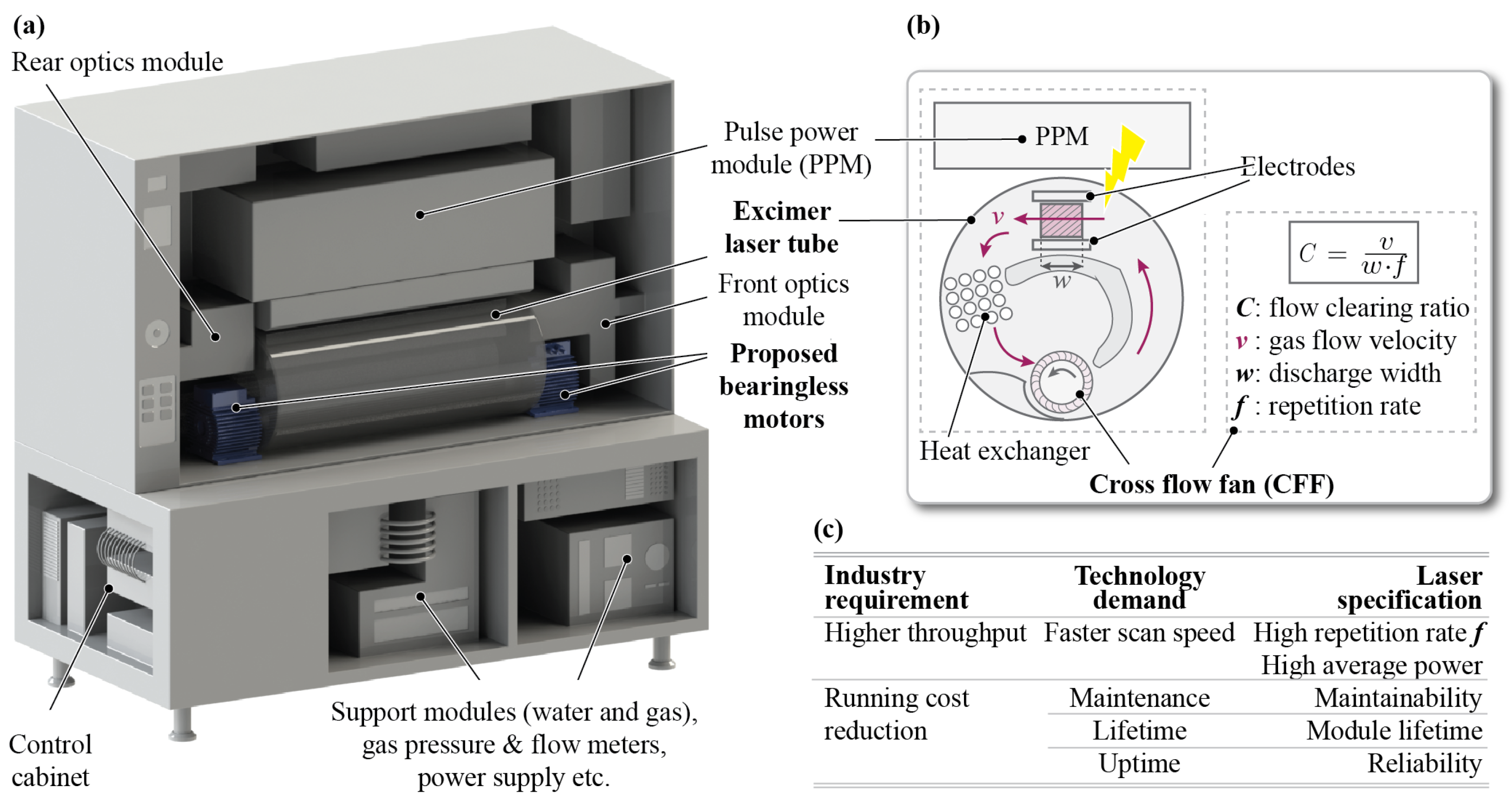
1. Introduction
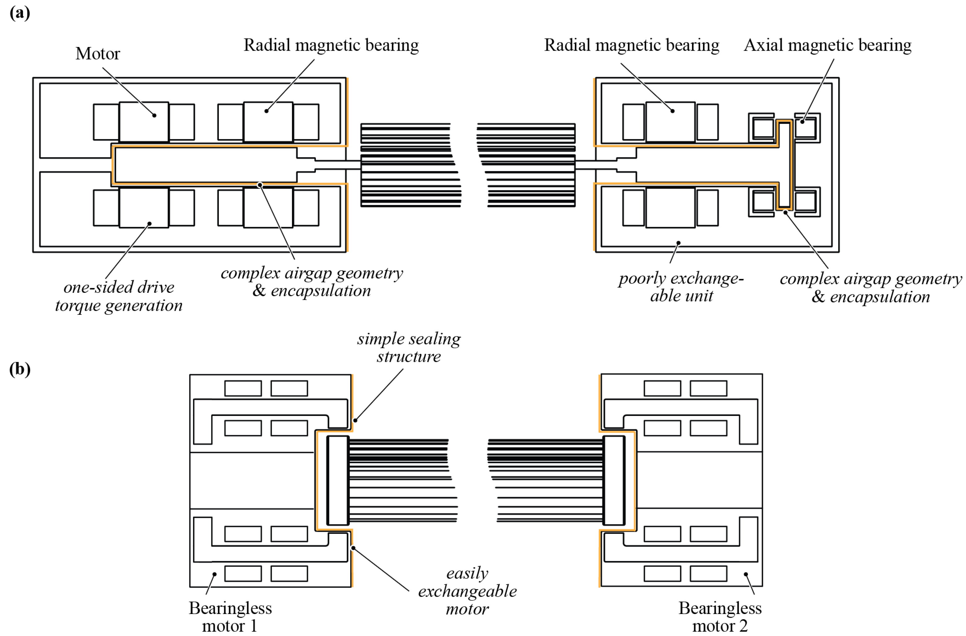
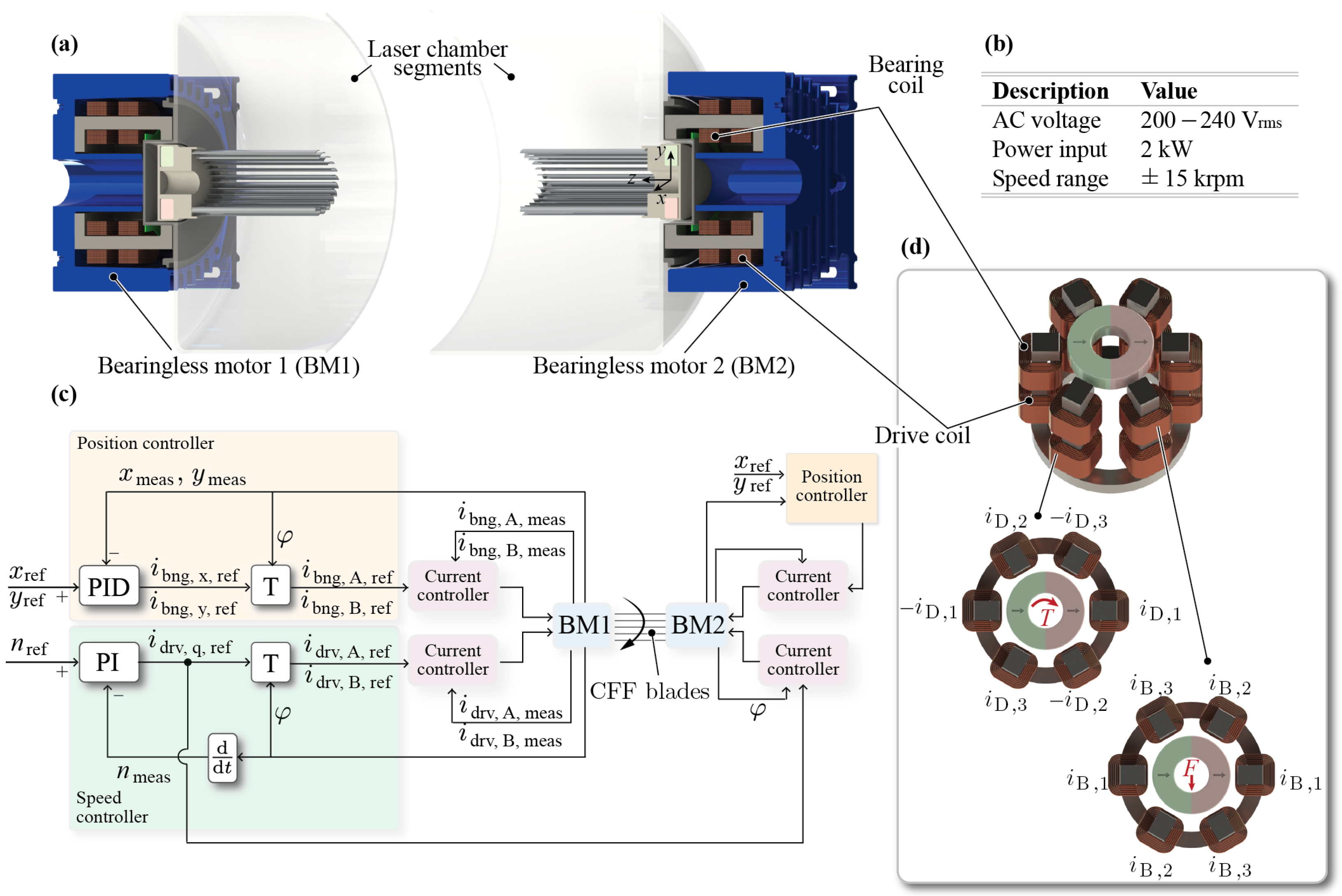
2. Bearingless Motor Topology
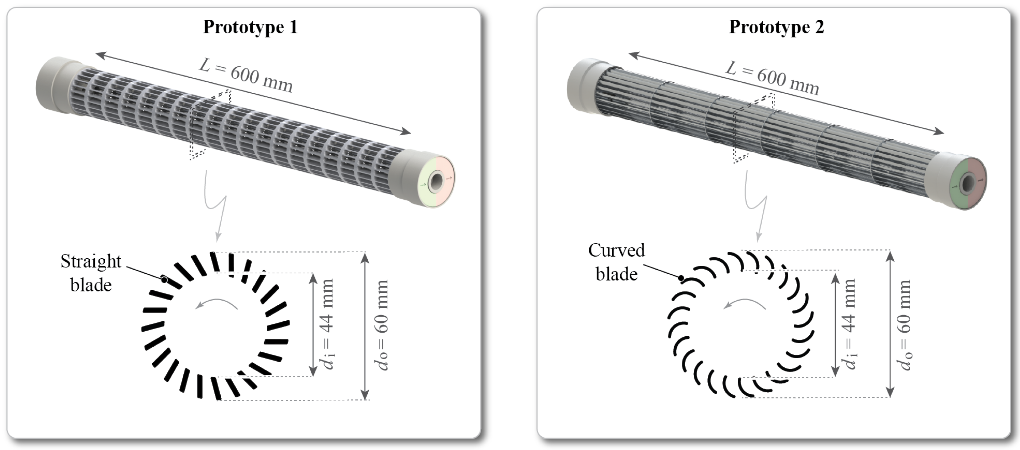
3. High-Speed Rotor Prototypes
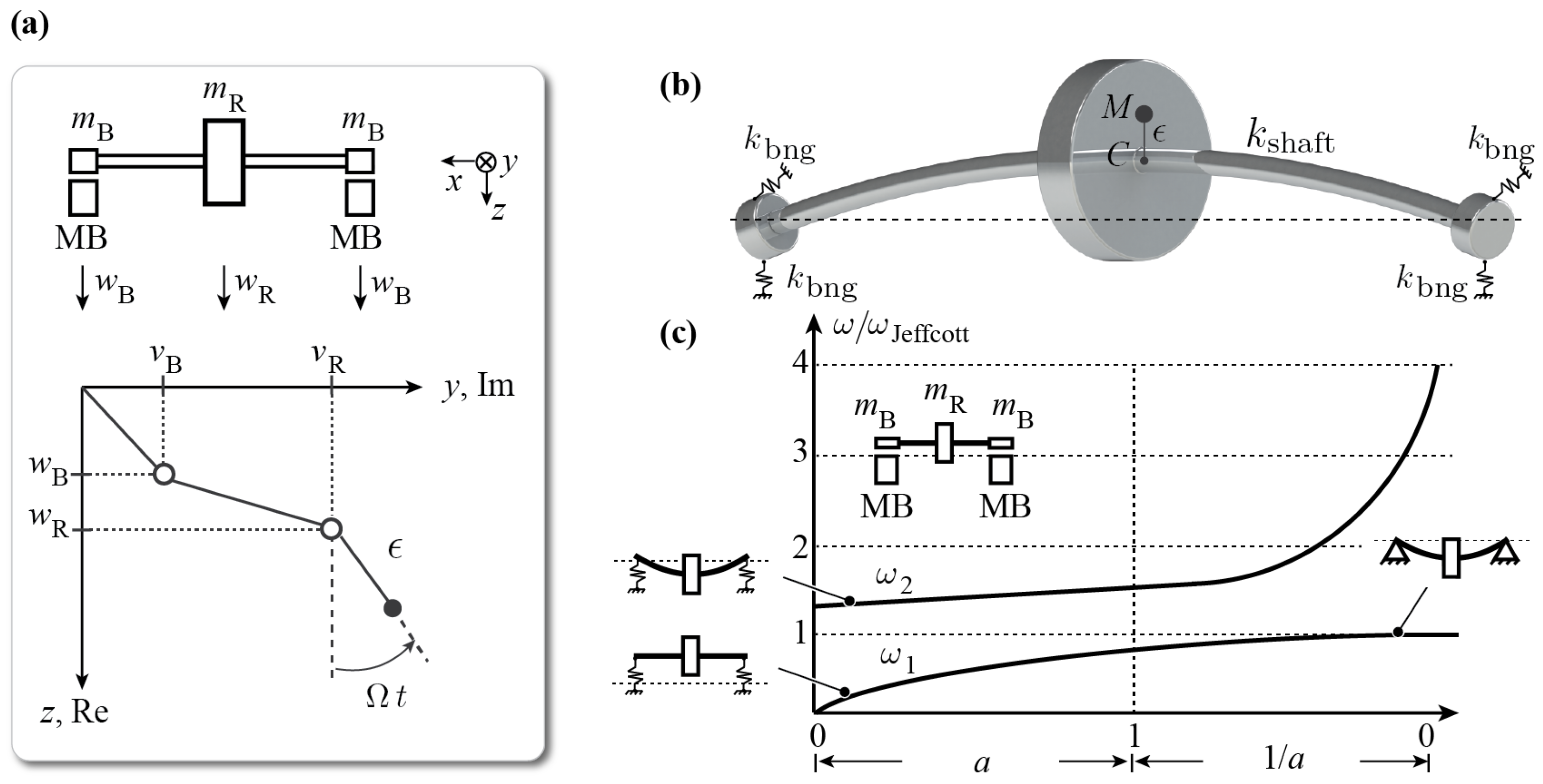
4. Rotor Dynamical Analysis
4.1. Analytical Description
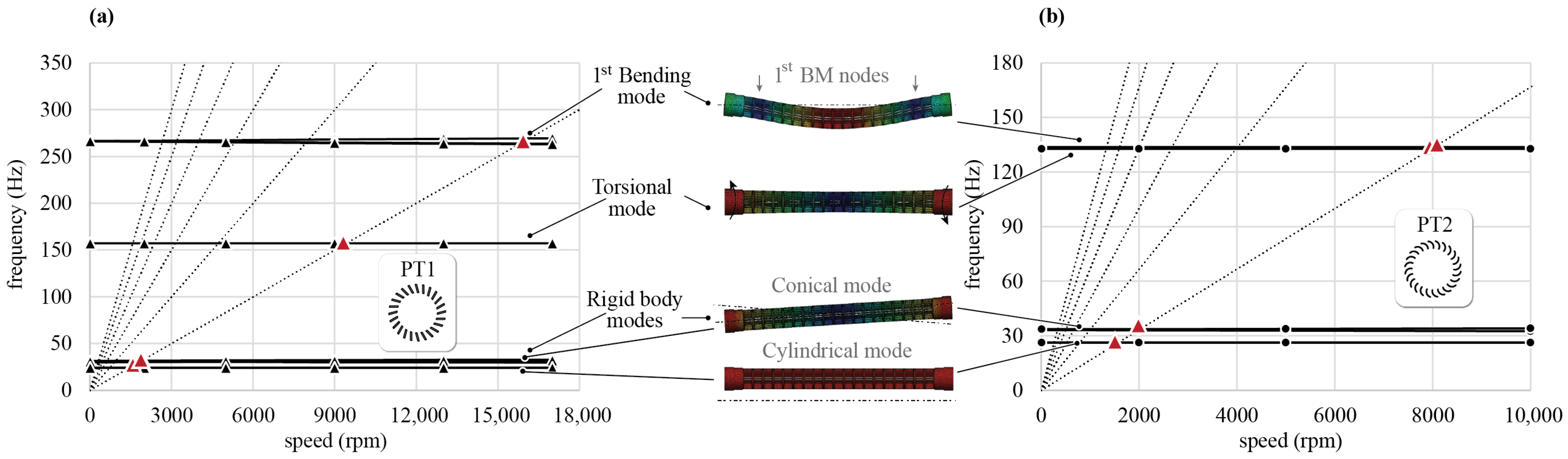
4.2. Simulated Modal Analysis
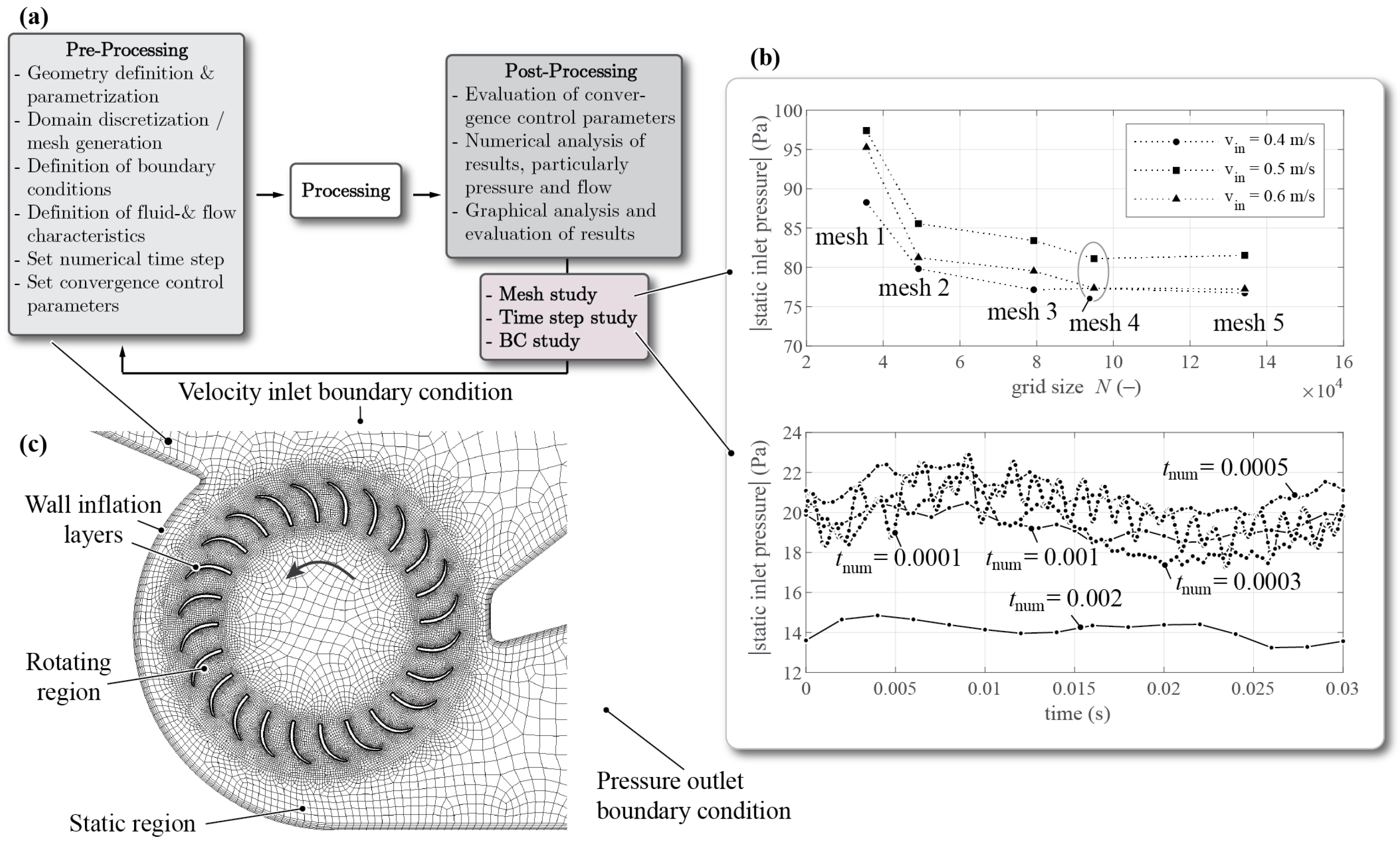
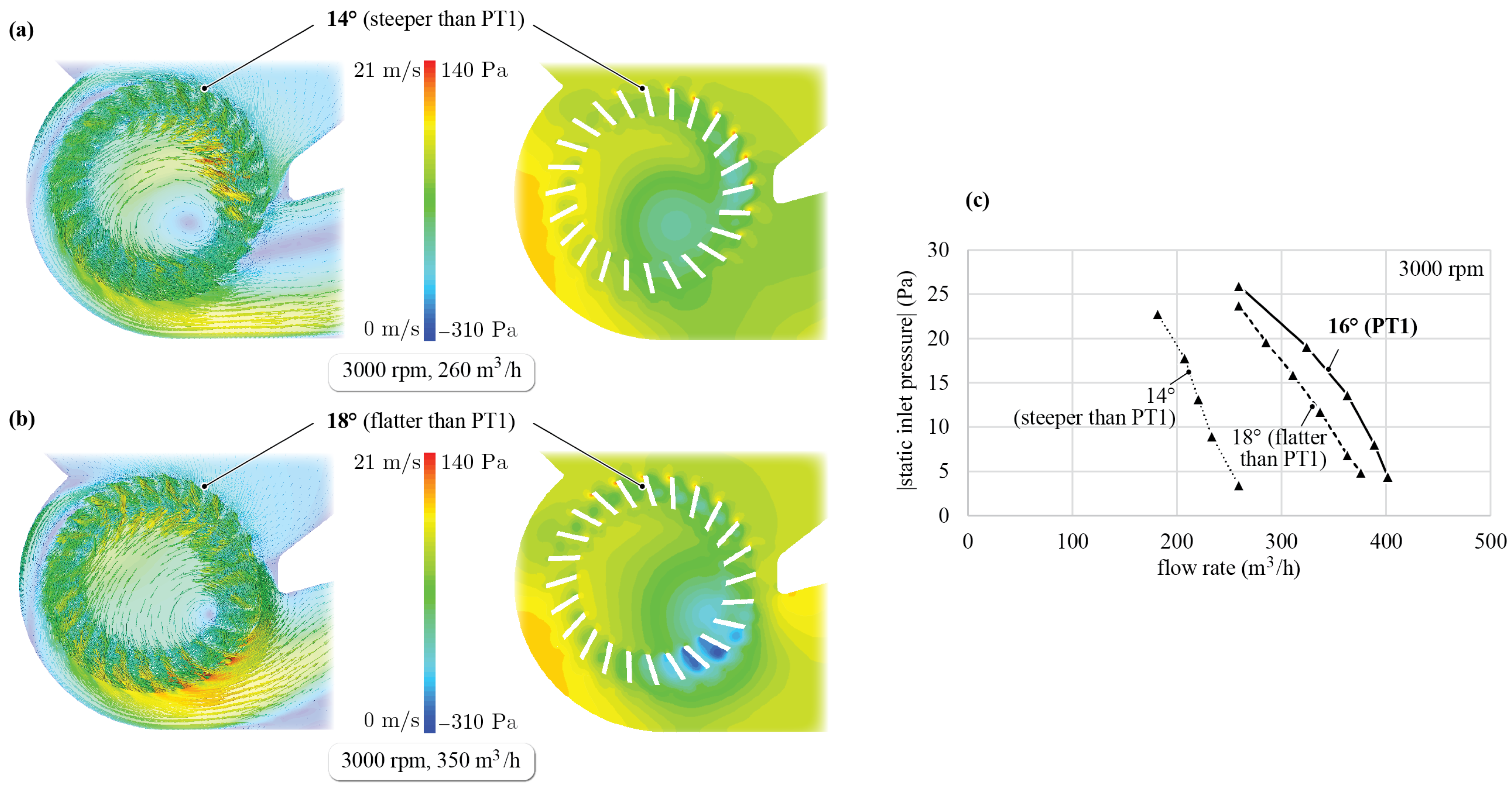
5. Fluid Dynamic Analysis
5.1. Numerical Method
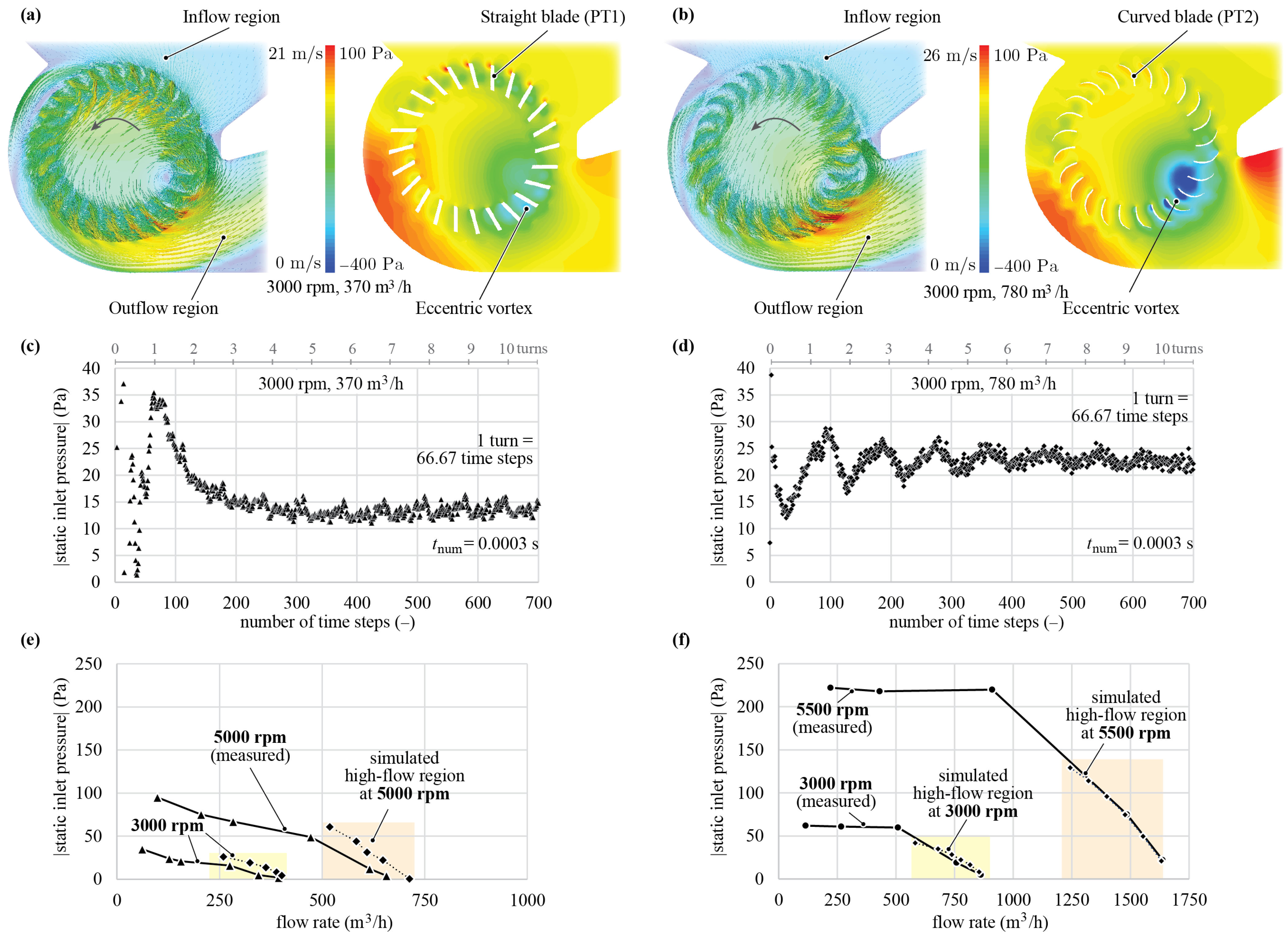
5.2. Results of Simulation
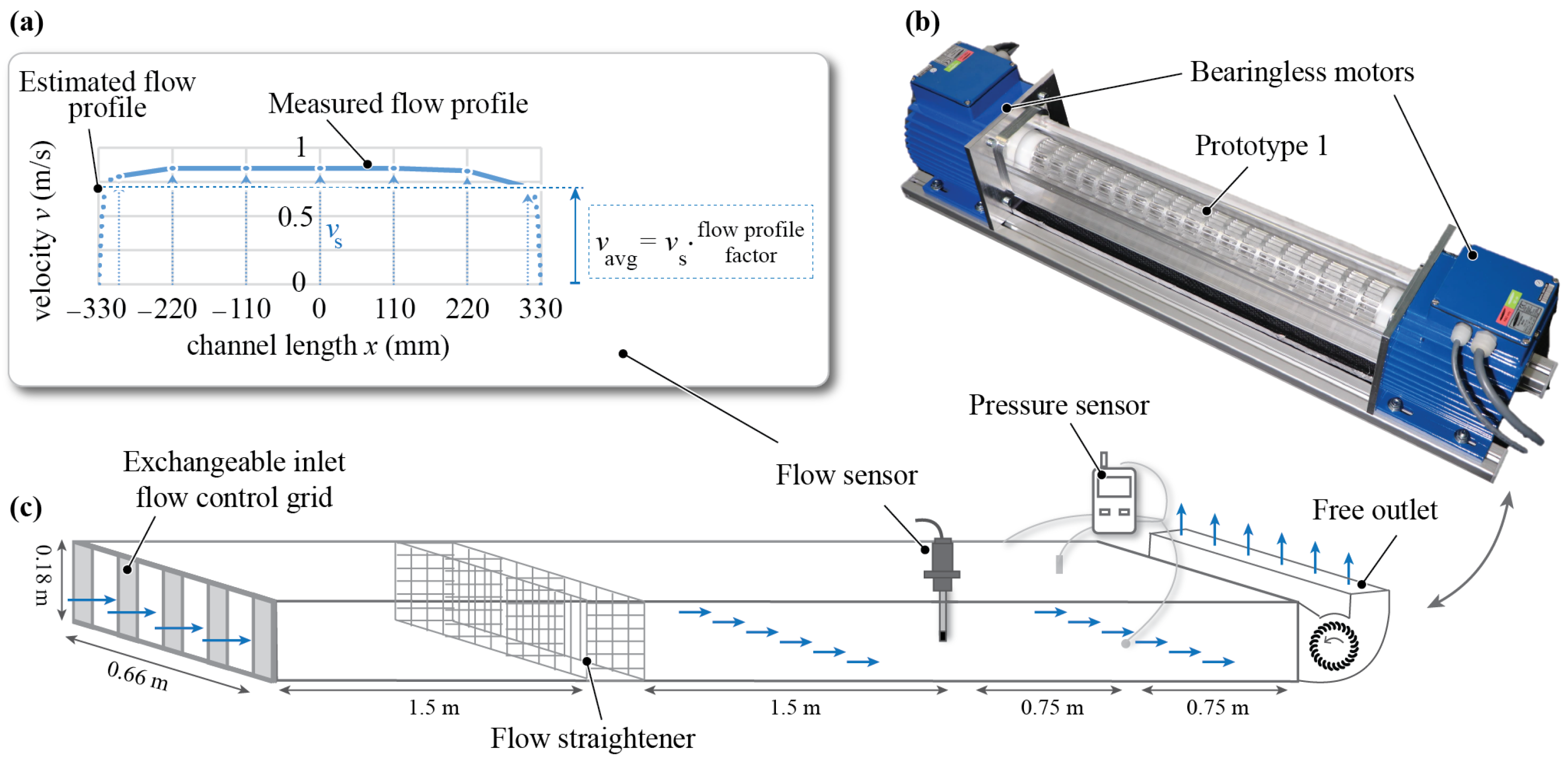
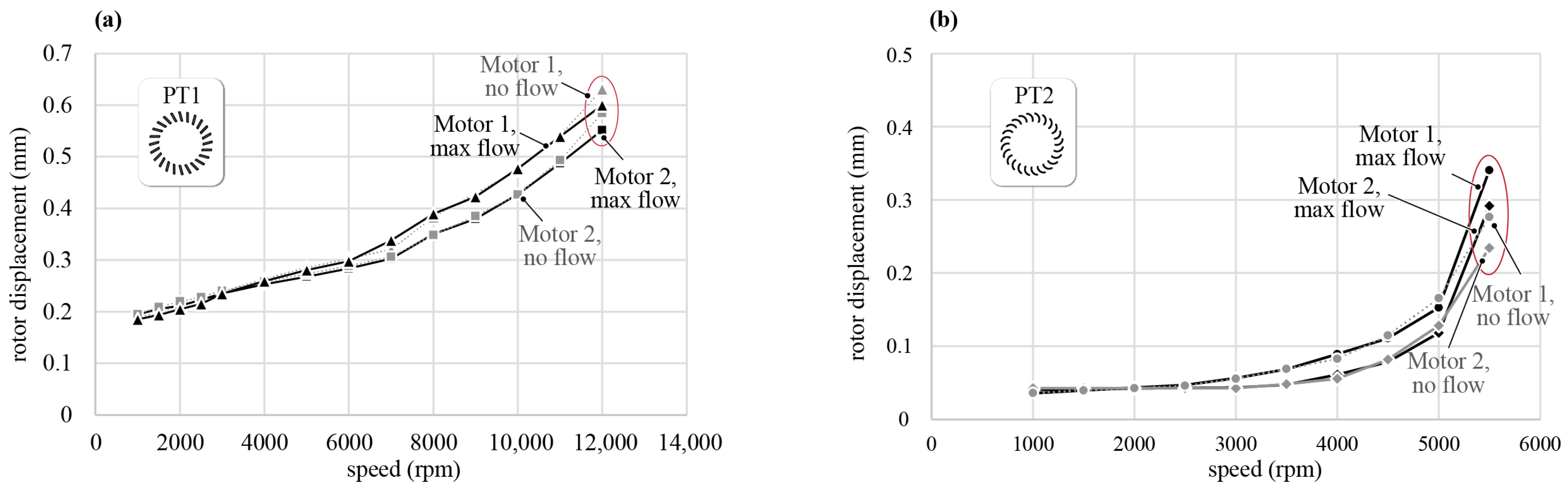
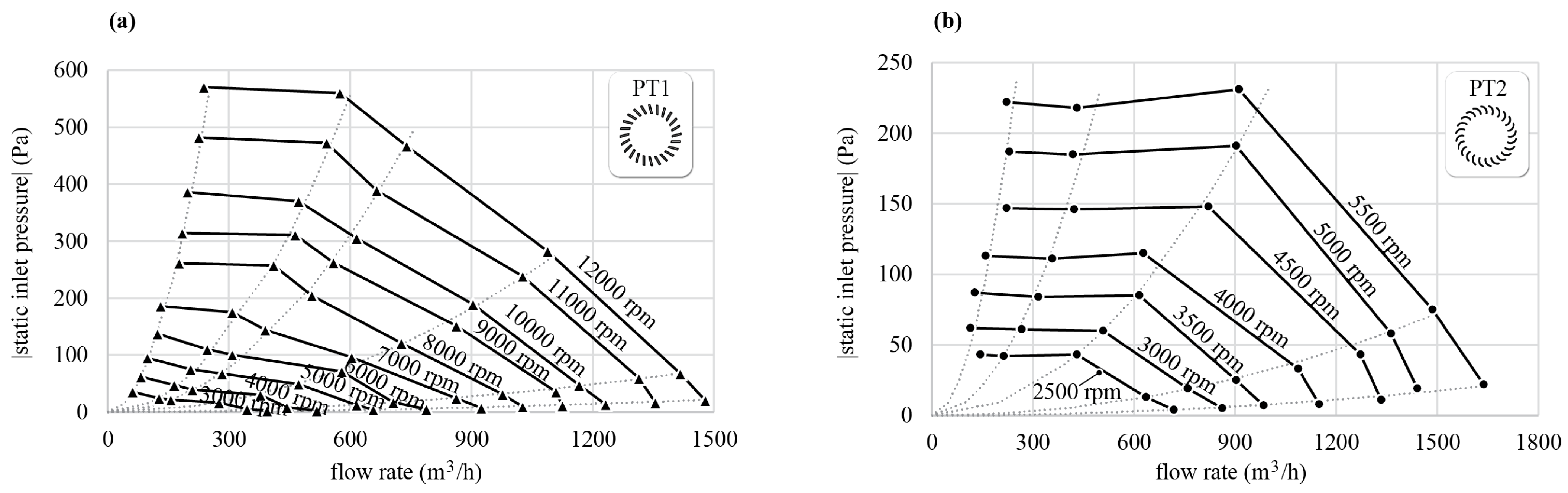
6. Experimental Analysis
6.1. Position Measurements of Rotor Magnets
6.2. Pressure–Flow Curves
7. Conclusions
Author Contributions
Funding
Data Availability Statement
Acknowledgments
Conflicts of Interest
References
- Basting, D.; Marowsky, G. Excimer Laser Technology; Springer: Berlin/Heidelberg, Germany, 2005; ISBN 978-3-642-05749-6. [Google Scholar]
- Basting, D.; Pippert, K.D.; Stamm, U. History and future prospects of excimer lasers. In Proceedings of the 2nd International Symposium on Laser Precision Microfabrication, Singapore, 16–18 May 2001. [Google Scholar]
- Borisov, V.M.; Vinokhodov, A.Y.; Vodchits, V.A.; Demin, A.I.; El’tsov, A.V.; Basting, D.; Stamm, U.; Voss, F. Compact 600-W KrF laser. Quantum Electron. 1998, 28, 119–122. [Google Scholar] [CrossRef]
- Borisov, V.M.; Vinokhodov, A.Y.; Vodchits, V.A.; El’tsov, A.V.; Ivanov, A.S. Development of high-power KrF lasers with a pulse repetition rate up to 5 kHz. Quantum Electron. 2000, 30, 783–786. [Google Scholar] [CrossRef]
- Borisov, V.M.; Vinokhodov, A.Y.; Vodchits, V.A.; El’tsov, A.V. On ultimate pulse repetition rates of an XeF laser. Quantum Electron. 2000, 30, 881–883. [Google Scholar] [CrossRef]
- Das, P.; Sandstrom, R.L. Advances in excimer laser technology for sub-0.25-μm lithography. Proc. IEEE 2002, 90, 1637–1652. [Google Scholar] [CrossRef]
- Sarkar, K.; Ujazdowski, R.C.; Das, P.P.; Larson, D.G. Excimer Laser with Magnetic Bearings Supporting Fan. U.S. Patent 5,848,089, 8 December 1998. [Google Scholar]
- Sekiguchi, S.; Shinozaki, H.; Aiyoshizawa, S.; Barada, T.; Ooyama, A. Magnetic Bearing and Circulation Fan Apparatus. U.S. Patent 6,519,273, 11 February 2003. [Google Scholar]
- Miki, M.; Wakabayashi, O. Gas Laser Apparatus and Magnetic Bearing Control Method. U.S. Patent 11,162,530, 2 November 2021. [Google Scholar]
- Sun, X.; Chen, L.; Yang, Z. Overview of bearingless permanent-magnet synchronous motors. IEEE Trans. Ind. Electron. 2013, 60, 5528–5538. [Google Scholar] [CrossRef]
- Warberger, B.; Kaelin, R.; Nussbaumer, T.; Kolar, J.W. 50-N·m/2500-W Bearingless motor for high-purity pharmaceutical mixing. IEEE Trans. Ind. Electron. 2012, 59, 2236–2247. [Google Scholar] [CrossRef]
- Chen, J.; Zhu, J.; Severson, E.L. Review of bearingless motor technology for significant power applications. IEEE Trans. Ind. Appl. 2019, 56, 1377–1388. [Google Scholar] [CrossRef]
- Gruber, W.; Bauer, W.; Wetsch, D.; Wex, B.; Kurita, N. Implementation of a bearingless axial-force/torque motor fan with flex-PCB windings. In Proceedings of the IEEE International Electric Machines & Drives Conference, San Diego, CA, USA, 12–15 May 2019; pp. 179–184. [Google Scholar] [CrossRef]
- Osa, M.; Masuzawa, T.; Yamaguchi, K.; Tatsumi, E. Double Stator Axial Gap Type Ultra-Compact 5-DOF Controlled Self-bearing Motor for Rotary Pediatric Ventricular Assist Device. IEEE Trans. Ind. Appl. 2021, 57, 6744–6753. [Google Scholar] [CrossRef]
- Bagaric, I.; Steinert, D.; Wassmer, F.; Holenstein, T.; Nussbaumer, T.; Kolar, J.W. Design and characterization of a bearingless cross-flow fan. In Proceedings of the IEEE/ASME International Conference on Advanced Intelligent Mechatronics (AIM), Delft, The Netherlands, 12–16 July 2021; pp. 1195–1200. [Google Scholar] [CrossRef]
- Steinert, D.; Nussbaumer, T.; Kolar, J.W. Slotless bearingless disk drive for high-speed and high-purity applications. IEEE Trans. Ind. Electron. 2014, 61, 5974–5986. [Google Scholar] [CrossRef]
- Gasch, R.; Nordmann, R.; Pfützner, H. Rotordynamik; Springer: Berlin/Heidelberg, Germany, 2006; ISBN 3-540-41240-9. [Google Scholar]
- Schweitzer, G.; Maslen, E.H. Magnetic Bearings; Springer: Berlin/Heidelberg, Germany, 2009; ISBN 978-3-642-10153-3. [Google Scholar]
- Toffolo, A. On the theoretical link between design parameters and performance in cross-flow fans: A numerical and experimental study. Comput. Fluids 2005, 34, 49–66. [Google Scholar] [CrossRef]
- Shih, Y.C.; Hou, H.C.; Chiang, H. On similitude of the cross flow fan in a split-type air-conditioner. Appl. Therm. Eng. 2008, 28, 1853–1864. [Google Scholar] [CrossRef]
- Dang, T.Q.; Bushnell, P.R. Aerodynamics of cross-flow fans and their application to aircraft propulsion and flow control. Prog. Aerosp. Sci. 2009, 45, 1–29. [Google Scholar] [CrossRef]
- Li, Y.; Ouyang, H.; Tian, J.; Du, Z.; Zheng, Z. Experimental and numerical studies on the discrete noise about the cross-flow fan with block-shifted impellers. Appl. Acoust. 2010, 71, 1142–1155. [Google Scholar] [CrossRef]
- Ouyang, H.; Tian, J.; Li, Y.; Zheng, Z.; Du, Z. Internal flow and noise investigations about the cross-flow fan with different blade angles. J. Turbomach. 2012, 134, 051023. [Google Scholar] [CrossRef]
- Zhang, W.; Yuan, J.; Si, Q.; Fu, Y. Investigating the In-Flow Characteristics of Multi-Operation Conditions of Cross-Flow Fan in Air Conditioning Systems. Processes 2019, 7, 959. [Google Scholar] [CrossRef]
- Eck, B. Ventilatoren; Springer: Bergin/Heidelberg, Germany, 1972; ISBN 3-540-05600-9. [Google Scholar]
- Lazzarotto, L.; Lazzaretto, A.; Martegani, A.D.; Macor, A. On cross-flow fan similarity: Effects of casing shape. J. Fluids Eng. 2001, 123, 523–531. [Google Scholar] [CrossRef]
- Dornstetter, S. Numerische und experimentelle Untersuchungen an Querstromventilatoren. Ph.D. Dissertation, Karlsruhe Institute of Technology, Karlsruhe, Germany, 2002. [Google Scholar]
- Lazzaretto, A. A criterion to define cross-flow fan design parameters. J. Fluids Eng. 2003, 125, 680–683. [Google Scholar] [CrossRef]


| Prototype 1 | Prototype 2 | |
|---|---|---|
| Material | Aluminium | Stainless steel |
| Mass of CFF blades | 890 g | 740 g |
| Total length | 680 mm | 680 mm |
| Fluid inlet length | 400 mm | 590 mm |
| Outer diameter | 60 mm | 60 mm |
| Inner diameter | 44 mm | 44 mm |
| Cross-sectional blade profile | Straight | Curved |
| Blade thickness | 1.4 mm | 0.5 mm |
Disclaimer/Publisher’s Note: The statements, opinions and data contained in all publications are solely those of the individual author(s) and contributor(s) and not of MDPI and/or the editor(s). MDPI and/or the editor(s) disclaim responsibility for any injury to people or property resulting from any ideas, methods, instructions or products referred to in the content. |
© 2023 by the authors. Licensee MDPI, Basel, Switzerland. This article is an open access article distributed under the terms and conditions of the Creative Commons Attribution (CC BY) license (https://creativecommons.org/licenses/by/4.0/).
Share and Cite
Bagaric, I.; Hu, R.; Steinert, D.; Nussbaumer, T.; Kolar, J.W. Comparative Evaluation of High-Speed Bearingless Cross-Flow Fan Designs for Lithography Excimer Lasers. Machines 2023, 11, 611. https://doi.org/10.3390/machines11060611
Bagaric I, Hu R, Steinert D, Nussbaumer T, Kolar JW. Comparative Evaluation of High-Speed Bearingless Cross-Flow Fan Designs for Lithography Excimer Lasers. Machines. 2023; 11(6):611. https://doi.org/10.3390/machines11060611
Chicago/Turabian StyleBagaric, Ivana, Rennan Hu, Daniel Steinert, Thomas Nussbaumer, and Johann Walter Kolar. 2023. "Comparative Evaluation of High-Speed Bearingless Cross-Flow Fan Designs for Lithography Excimer Lasers" Machines 11, no. 6: 611. https://doi.org/10.3390/machines11060611
APA StyleBagaric, I., Hu, R., Steinert, D., Nussbaumer, T., & Kolar, J. W. (2023). Comparative Evaluation of High-Speed Bearingless Cross-Flow Fan Designs for Lithography Excimer Lasers. Machines, 11(6), 611. https://doi.org/10.3390/machines11060611