Article

Shock Absorption for Legged Locomotion through Magnetorheological Leg-Stiffness Control

1
School of Mechanical, Materials, Mechatronic, and Biomedical Engineering, University of Wollongong, Wollongong, NSW 2522, Australia
2
CAS Key Laboratory of Mechanical Behavior and Design of Materials, Department of Precision Machinery and Precision Instrumentation, University of Science and Technology of China, Hefei 230027, China
3
School of Electrical, Computer & Telecommunications Engineering, University of Wollongong, Wollongong, NSW 2522, Australia
*
Authors to whom correspondence should be addressed.
Machines 2023, 11(2), 236; https://doi.org/10.3390/machines11020236
Submission received: 20 December 2022 / Revised: 20 January 2023 / Accepted: 2 February 2023 / Published: 6 February 2023
(This article belongs to the Special Issue Low-Frequency Vibration Control with Advanced Technologies)

Abstract

:
The objective of this study was to evaluate the performance of a magnetorheological-fluid-based variable stiffness actuator leg under high impact forces through optimal tuning and control of stiffness and damping properties. To achieve this, drop testing experiments were conducted with the leg at various drop heights and payload masses. The results showed that while lower stiffness and higher damping can lead to lower impact forces and greater energy dissipation, respectively, optimal control can also protect the leg from deflecting beyond its functional range. Comparison with a rigid leg with higher damping showed a 57.5% reduction in impact force, while a more compliant leg with lower damping results in a 61.4% reduction. These findings demonstrate the importance of considering both stiffness and damping in the design of legged robots for high impact force resistance. This simultaneously highlights the efficacy of the proposed magnetorheological-fluid-based leg design for this purpose.

1. Introduction

Humans and animals make use of so-called ‘preflexes’ and reflexes that modulate effective leg stiffness to manage impacts [1,2,3,4,5]. Despite this, stiffness control in robot legs has not been directly investigated in drop landings within literature. From a biological perspective, modulation of leg stiffness generally precedes disturbances to terrain elevation [6,7,8,9] in order to mitigate injuries to the musculoskeletal system. Other circumstances, such as a variation in terrain stiffness, may also be compensated for through similar modulation [10,11,12]. Focusing on the mechanism for impact compensation during drops or jumping in place, studies on humans have been reported for several decades [3,13,14,15,16,17,18,19,20], with experimental drop heights of up to 1.93 m [13]. While different mechanisms have been attributed to impact force attenuation during drop jumps or drop landings [16], decreasing effective leg stiffness during an impact has been shown to reduce peak forces [14,15].
For mechanical shock absorption systems in applications such as motor vehicles or helicopter landing gear, magnetorheological (MR) materials have been explored widely as potential solutions to shock-induced vibration and impact loads [21,22,23,24]. In various real-world scenarios, stiffness control using MR materials, particularly MR fluid (MRF) could help mitigate costly damages to sensory equipment or prevent complete robot failure. Successful recovery from trivial missteps or more substantial drops within rugged terrain could be the difference between a successful mission and a failed task for a robot. Although it is clear that the actuators of a robot can benefit from passive and variable series elasticity in terms of impact management, efficiency, and general robustness [25,26,27,28], impact loading of robot legs with variable stiffness has not yet been reported. Hence, the extent to which MRF-based leg stiffness control can benefit legged robot shock absorption was studied herein.
In this paper, the MRF-based variable stiffness actuator leg mark II (MRVSAL-II) was evaluated through impact loading scenarios, focusing on the potential for variable stiffness in a robot leg to improve shock absorption. First, a drop-test impact-loading system was constructed to conduct impact loading experiments. Employing this system, passive performance evaluation was conducted by comparing the MRVSAL-II performance with a comparable rigid leg with relatively high stiffness and damping and a soft leg with relatively low stiffness and damping. Based on experimental performance, an adaptive impact-buffering controller was developed for the MRVSAL-II, which was investigated for its impact mitigation capability.
Following on from the introduction, this paper is organised as follows. Section 2 outlines the functionality of the MRVSAL-II. Section 3 details the experimental impact system. Section 4 outlines the experimental procedure. Section 5 presents the passive impact results. Section 6. introduces an impact force controller and presents the controlled impact results. Section 7 draws conclusions from the study.

2. MRVSAL-II Mechanism

This new leg design, included recently in locomotion studies conducted by the authors [29], features a torque-actuated variable stiffness mechanism that is coaxial with the hip joint of the leg. This improves the rotational balance of the leg, reducing energy cost and increasing stability, as compared with the off-centre leg joint of the former C-shaped leg [30]. The leg consists of a lower leg segment and an upper leg segment that are connected by a draw cable through the variable stiffness mechanism, as shown in Figure 1a. These leg segments are made of 3D printed, low-density Nylon-fiberglass composites produced using a Markforged II FDM 3D printer. When the leg is compressed through contact with the ground via the rubber foot pad, the tension force on the draw cable generates a torque on the variable stiffness mechanism via the cable pulley of the damper housing. The cross-section of the variable stiffness mechanism, shown in Figure 1b, includes a rotary MR damper that can provide a variable level of damping torque based on the applied electric current through a set of solenoids and corresponding magnetic field penetrating the MR fluid. The draw cable from the lower leg segment connects to the damper housing port, causing deflection of a relatively soft torsional spring k s o f t as well as rotation of the damper housing. If the damping torque is sufficient, the housing becomes coupled with the damper rotor, which then engages a secondary, relatively stiff spring k s t i f f . With these springs acting in parallel, the effective mechanism stiffness is k s o f t when the damping torque is close to zero and ( k s o f t + k s t i f f ) when the damping torque is increased. By continuously and rapidly varying the damper current and thereby damping torque, the leg can achieve a stiffness range between these two extremes. For this leg design, the damper current has a range of 0 A to 3 A, given the damper magnetically saturates towards 3 A. Comprehensive characterisation and mathematical modelling of the interaction between damper current and the leg mechanism stiffness and damping is detailed in [29].

3. Experimental Setup

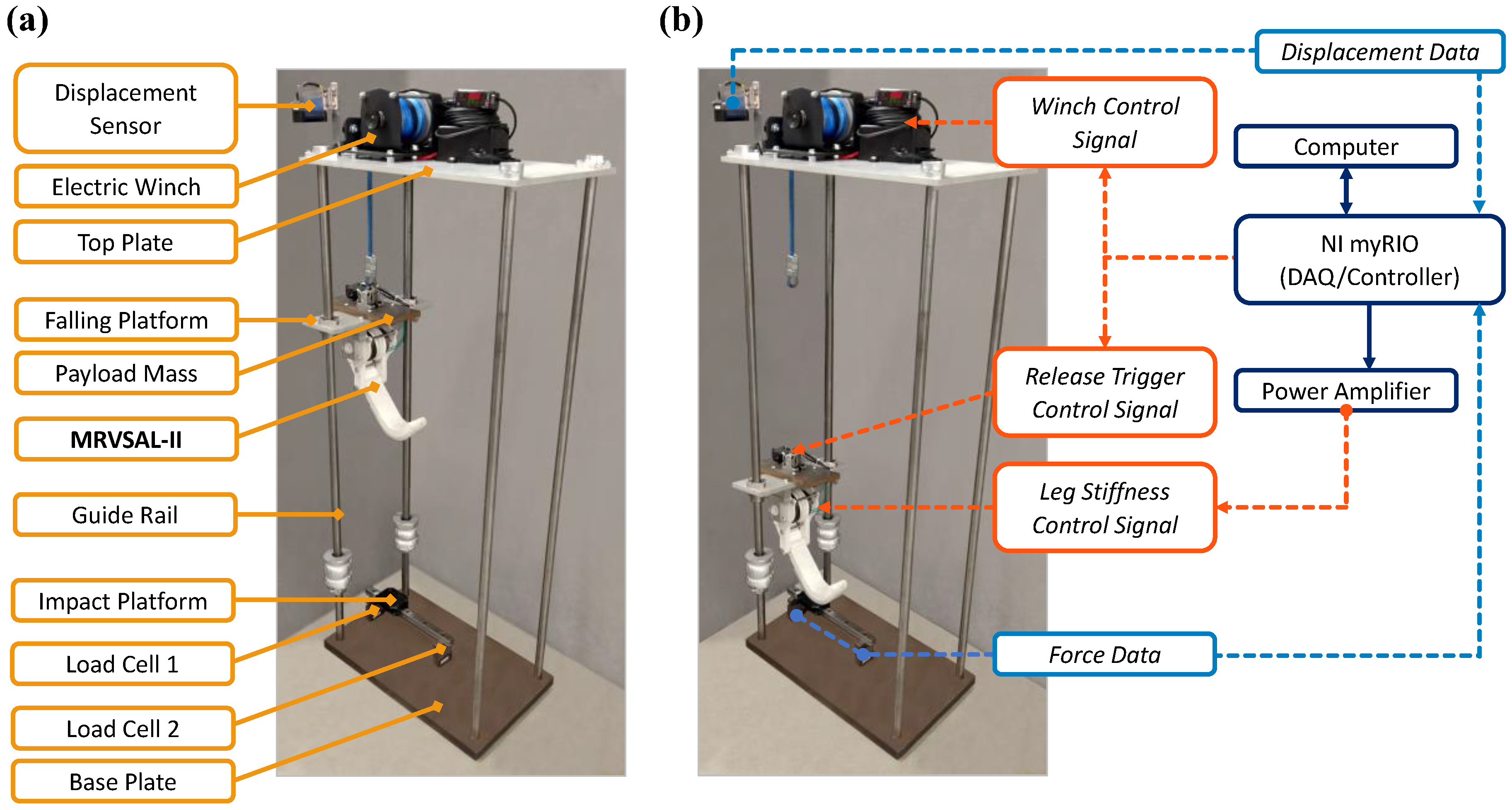
To conduct the impact loading experiments of the MRVSAL-II, the drop-test system illustrated in Figure 2 was developed. This system makes use of a rigid frame with four parallel 20 mm rails of 1.2 m length. Given the dimensions of the system and leg, a maximum drop height d d r o p of 600 mm can be set between the foot pad of the leg and impact platform. Two of these rails guide the falling platform to which the leg is rigidly affixed. The platform includes a removable 1.95 kg payload mass, which combines with the platform mass and leg mass to provide adjustable total falling masses m t o t a l of 2.65 kg and 4.6 kg for the single leg. To set the drop height of the leg, an electric winch (XBULL3000LBS, X-Bull) is controlled to reach a desired vertical displacement using a laser displacement sensor with 800 mm range (IL-600/IL-1000, Keyence). This laser also serves to measure the displacement d C O M y of the falling platform through the impact, which has an initial value or datum position of 220 mm at the moment of impact, as illustrated in Figure 3a. The drop height d d r o p is therefore taken as the elevation from the datum position of the leg. A servomotor-controlled release mechanism then allows the falling platform to be dropped upon command. After a certain level of leg deflection, the pivot point between the upper and lower leg segments will also collide with the impact platform, with a maximum leg stroke of approximately 123 mm, illustrated in Figure 3a as d l i m . To facilitate leg deflection in the sagittal plane, a low-inertia linear rail platform is located directly below the foot pad of the leg. This rail is supported by two S-type load cells (MT501-100 kg, Millennium Mechatronics), from which the measurements can be summed to provide the resulting impact force. This is illustrated between Figure 3a,b, where it is shown that irrespective of the position of the leg through the deflection, the impact force is always F R y = F L C 1 + F L C 2 , where F L C 1 and F L C 2 are the forces measured by the two load cells. The included rotary MR damper within the MRVSAL-II is powered with an amplified control signal from the system controller (myRIO-1900, National Instruments), which additionally acts as the DAQ for data logging.

4. Experimental Procedure

To investigate the performance of the MRVSAL-II during impact loading, the leg was controlled to be dropped at a series of drop heights d d r o p from 100 mm to 600 mm in 100 mm increments. These drop heights correspond to a range of impact velocities v i m p a c t , respectively, from 1.40 m/s to 3.43 m/s. Both the falling platform with and without the payload mass was tested, providing two scenarios for the total falling masses of 2.65 kg and 4.60 kg. For the passive performance of the leg, damper current was varied from 0 A to 3 A in 1 A increments, referred hereafter as the ‘passive control modes’. Where impact force control was applied, constant current was maintained during the impact. As well as the normal operating modes for the MRVSAL-II, two additional scenarios were arranged for these tests: one where the damper was effectively removed, the ‘no damper’ case, and one where the leg was made ‘rigid’ by fixing the upper and lower leg segments. Together, these represent two extremes, where the leg was very soft with low damping and very stiff with high damping, respectively. In either case, total falling mass was maintained to be identical to the other test scenarios. Each impact was conducted over a 5 s period, later cropped down to a 1 s period starting from the moment of impact when the load cells registered a non-zero value. This point in time corresponds to the initial COM height of the leg, i.e., d C O M y ( t = 0   s ) = 220   mm , and impact velocity v C O M y ( t = 0   s ) = v i m p a c t , as illustrated in Figure 3a.

5. Passive Control

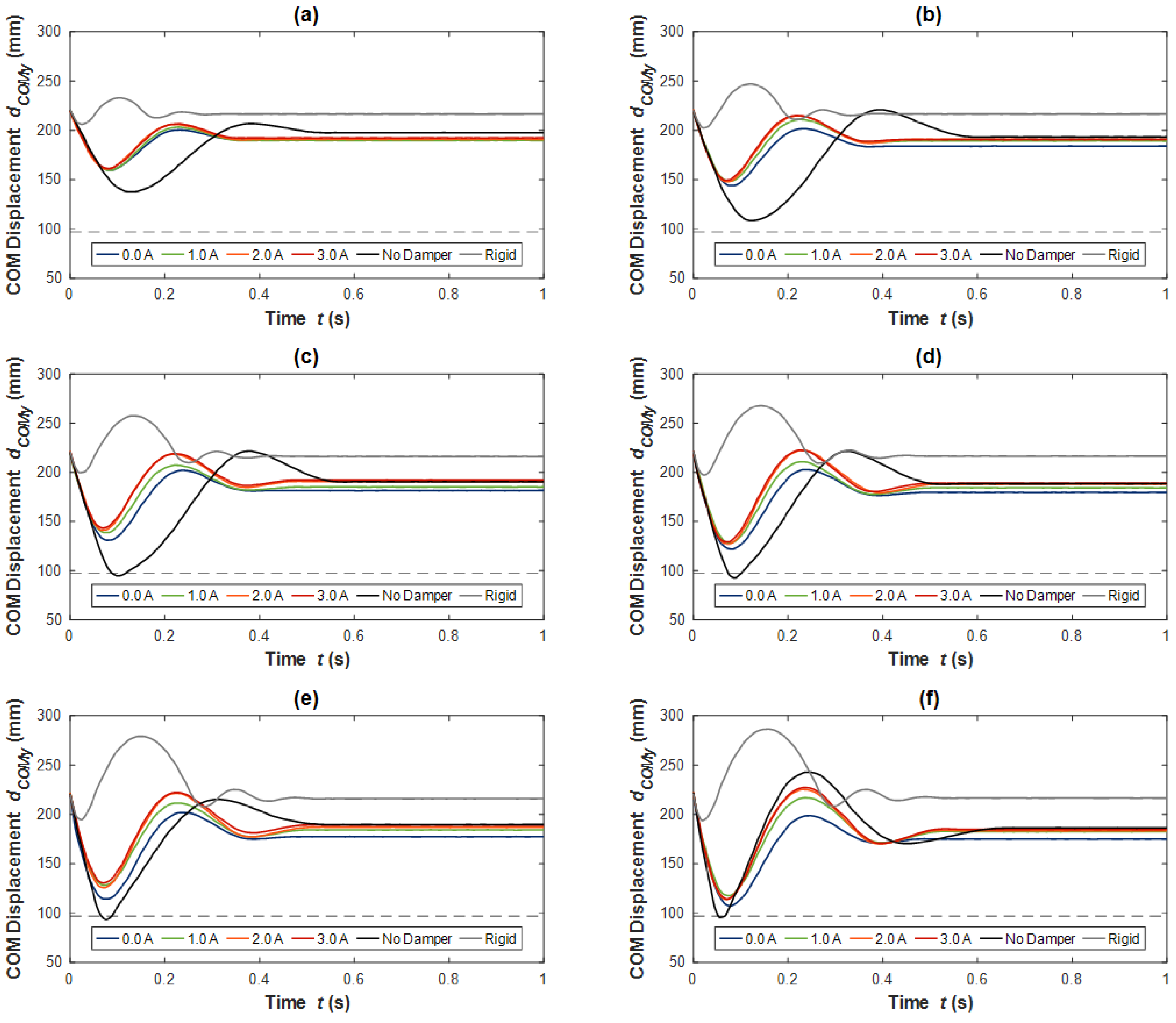
Included in Figure 4a–f are the COM vertical displacements d C O M y of the MRVSAL-II during the passive impact tests with the 2.65 kg total mass as drop height d d r o p which was increased from 100 mm to 600 mm. Additionally indicated in each plot is the COM displacement which corresponds to the leg stroking out, approximately 97 mm, i.e., d C O M y ( t = 0   s ) d l i m . When the COM displacement reached this threshold, a collision occurred following the initial landing of the leg’s foot pad and impact platform, influencing the dynamic behaviour of the leg during the impact. It should be noted that this did not occur for all tests and could be observed where d C O M y 97   mm .
From Figure 4a, what is initially apparent is that for the no damper case, the deflection range for the leg is the largest, accompanied by the greatest settling time of 0.47 s. On the other hand, the rigid leg behaved quite differently, even entering ballistic flight as the leg bounced upon impact. Despite this, the rigid leg settled very quickly, within 0.15 s. In between these two extreme scenarios was where we found the passive damper control modes. On a scale comparable to the extreme scenarios, not much variation between currents was observable; however, it was noticeable that at 0 A the leg deflected more and had a lower rebound than that of the 3 A case, which rose 5.90% higher. As drop height was increased, these trends became more apparent, as observed in Figure 4b. For greater drop heights, i.e., Figure 4c–f, it appeared that the no damper case resulted in collision with the ground due to what appears to be a combined effect of relatively low stiffness and low damping ratio. This is quite reasonable, given the removed rotary MR damper which governs the stiffness adjustment and contributes quite high damping to the system. Despite the high impact energy for the 600 mm drop height, as seen in Figure 4f, no passive control mode resulted in collision, although, the 0 A case was not far from it.
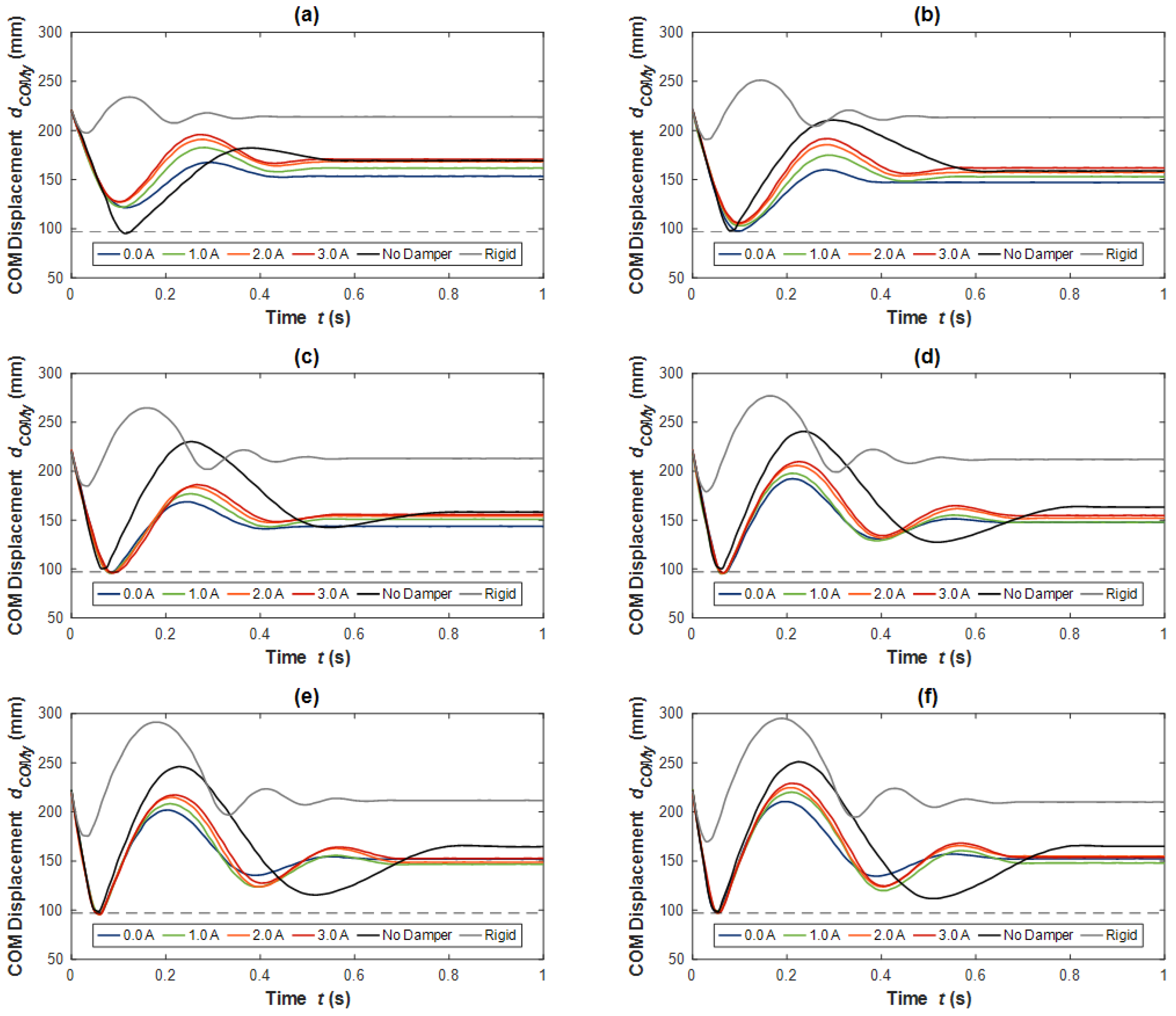
When the total falling mass was increased to 4.60 kg, the COM displacements for all tests became more violent, indicated in Figure 5, given the impact energy nearly doubled for these cases. It is seen in Figure 5a that even for a 100 mm drop height, the no damper case resulted in collision. There was also more substantial variation between the passive control modes, where it is seen that the 3 A case resulted in a rebound that was 40.1% greater than that of the 0 A case. At the 200 mm drop height of Figure 5b, the passive control modes approached the collision threshold, with the 0 A case very narrowly avoiding collision. At this stage, it became challenging to distinguish the collision scenarios, however, so this is discussed shortly with respect to the measured impact forces. Although, what did occur here was a transition during the 300 mm impact shown in Figure 5c, where some of the passive control modes experienced collision, but others avoided it by a small margin. In all tests following this, i.e., those shown in Figure 5d–f, all modes except for the rigid leg resulted in collision as the leg deflected to its maximum range.
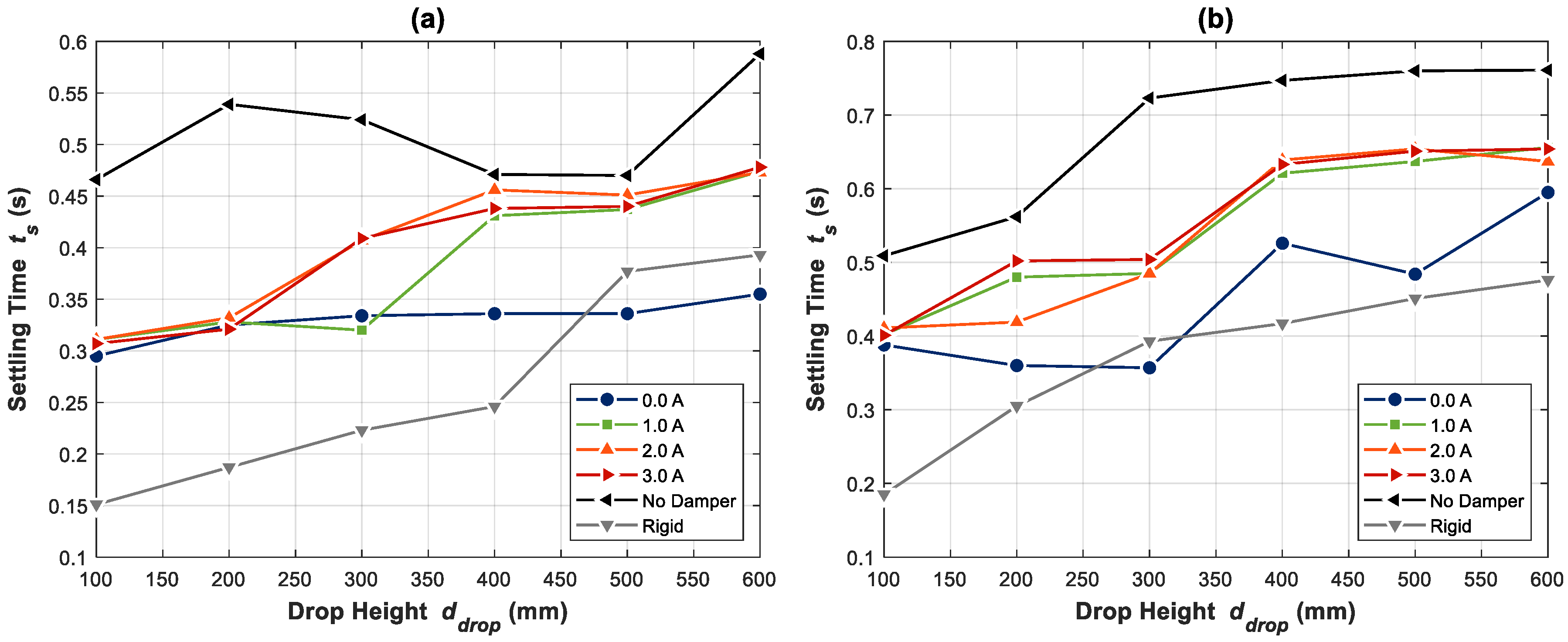
In terms of the rate at which the impact energy is dissipated, the settling time t s for the COM displacement was investigated, as plotted in Figure 6. This is indicative of the rate of energy dissipation, with the vertical kinetic energy E K y being a function of the COM vertical velocity v C O M y . Starting with the fastest settling times, these were generally found for the rigid leg case, indicating this scenario resulted in the greatest effective damping coefficient during impacts for a given mass. This can be explained by a few contributing mechanisms which were specific to the tests with the rigid leg. First, for every single test, the leg COM later exceeded the impact initial height of 220 mm. This is consistent with the bouncing behaviour observed during tests. As a consequence, more work was performed by the rubber foot pad attached to the leg in dissipating energy. This was further exaggerated by the relatively high stiffness of the leg, leading to greater compression of the foot pad than in other tests. It is also likely that there was greater flexure in the 3D-printed leg structure, causing greater internal energy dissipation. In great contrast, the no damper case led to the anticipated lowest effective damping coefficient, as indicated by the high settling times for these tests. For a legged robot, this would result in high vibration of the platform, which could lead to more collisions and erratic behaviour. As a reasonable middle ground, the settling times and hence energy dissipation rate of the passive controlled cases generally exist between the no damper and rigid cases. The tendency was for the 0 A cases to result in lower settling times, but as current increased towards 3 A, settling time increased. What this shows is that the effective damping coefficient for the leg during impacts is inversely related to damper current. Noting the difference in y -axis scales between Figure 6a,b, with greater mass comes greater settling time, which is anticipated as the decay constant ζ ω n for a typical dynamic system decreases with increased mass.
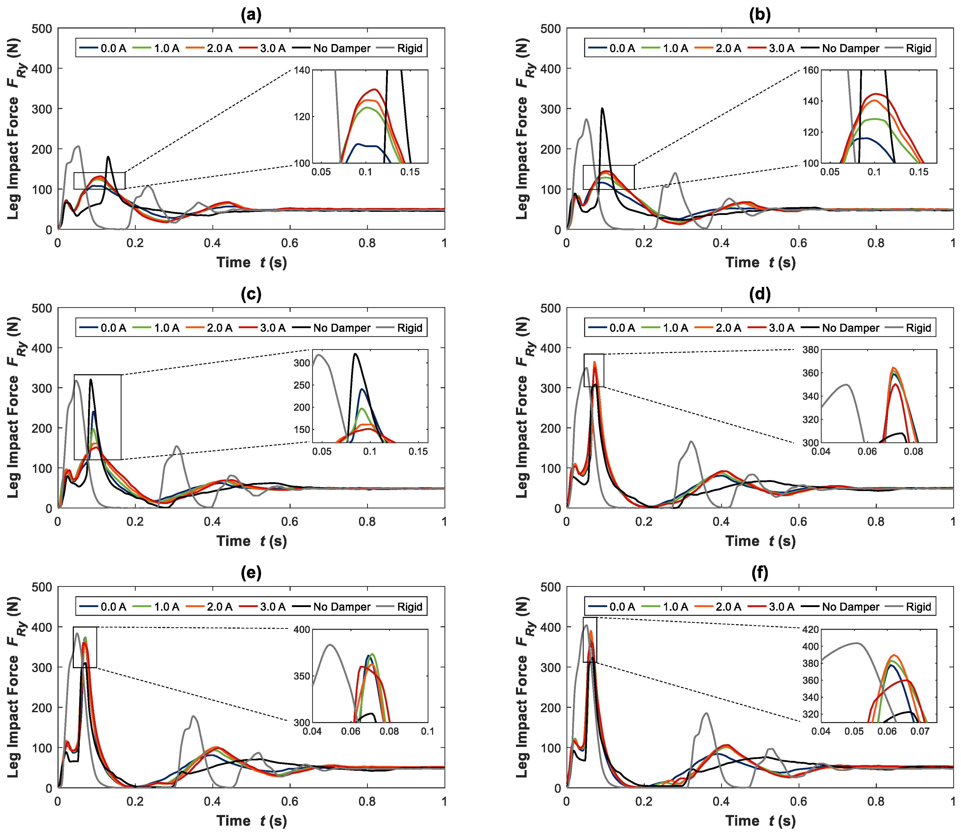
Of greater concern to us than the displacement of the leg is the impact force, given this can directly result in failure of robot parts or components, also gradually causing damage through fatigue. For the 2.65 kg total mass, the measured leg impact force F R y is reported in Figure 7. Starting with the 100 mm drop height, Figure 7a reflects the displacement behaviour observed in Figure 4a. In particular, the ballistic flight of the rigid leg as it bounced can be observed here too where the force reduced to zero. As expected, this rigid leg and the bouncing behaviour also resulted in the greatest impact force, reaching 123 N in this case. Secondary to this were the passive control modes, reducing in force from 3 A to 0 A, followed by the no damper case with a peak impact force of 59.9 N. The other notable behaviour, present in all tests other than those of the rigid leg, was the initial peak in the force prior to the subsequent and usually largest peak. Based on observations made during testing, it seems the angle of the draw cable between the lower leg segment and variable stiffness mechanism was close to 0° from the y -axis. This made the leg relatively stiffer for the few millimetres of deflection, explaining the short rise in force which subsides until the maximum deflection of the leg was reached.
Although impact force increased in tests shown between Figure 7a,c, it was not until that in Figure 7d when the first collision with the ground occurred for the no damper case. While the displacement of the leg shown in Figure 4c indicates collision occurred, it is a marginal case here, given no substantial secondary peak in impact force was observed. From Figure 7d–f, however, this peak became very obvious, even surpassing the peak force of the rigid case for the 600 mm drop height where a value of 242 N was reached. While the peak force of the rigid cases was always exceptionally high, for these greater drop heights with this mass, it is evident the no damper case also provided unsatisfactory performance. When the leg made use of the designed passive control modes, a more reasonable range of peak force between about 75 N to 140 N was maintained. Here it is found that the 0 A case consistently provided the optimal performance over other passive currents, always resulting in the minimum peak force for the MRVSAL-II. For the 600 mm drop height, this represents a reduction in peak force of 20.1% from the 3 A force of 135 N to 0 A force of 108 N.
In contrast to the impacts with the lower mass, the tests conducted with the 4.60 kg total mass, included in Figure 8, indicate collision occurs for the no damper case in all tests. Where no such collision occurred, compared with the 2.65 kg total mass tests, peak impact force for all tests was increased by a factor of roughly 1.5, somewhat lower than the 1.74 factor by which the mass was increased. Of more relevance to managing these impacts, however, it is observed that no collision occurred for any passive control mode for the 100 mm and 200 mm drop heights, included in Figure 8a,b, respectively. Where it was challenging to distinguish from displacement data alone in Figure 5c, here in Figure 8c, the corresponding 300 mm tests showed that the passive control modes also started to result in collisions. Where impacts with lower mass or drop heights previously indicated the 0 A passive control mode was always optimal, it is evident here that it was the worst-performing current setting. In contrast to the recorded 241 N peak force of the 0 A case, a reduction of 37.3% to 151 N was obtained through the 3 A case. While some variation between other passive control modes was found for greater drop heights, it can be seen from Figure 8d–f that the minimum peak impact force was consistently obtained for the MRVSAL-II by the 3 A current setting. It can also be observed that when significant collisions did occur, i.e., those seen here beyond 300 mm drop heights, the no damper case actually resulted in a lower impact force. Although, coupled with a lower effective damping coefficient, as indicated by the longer settling times of Figure 6b, impact energy was dissipated over a longer period for the no damper case.
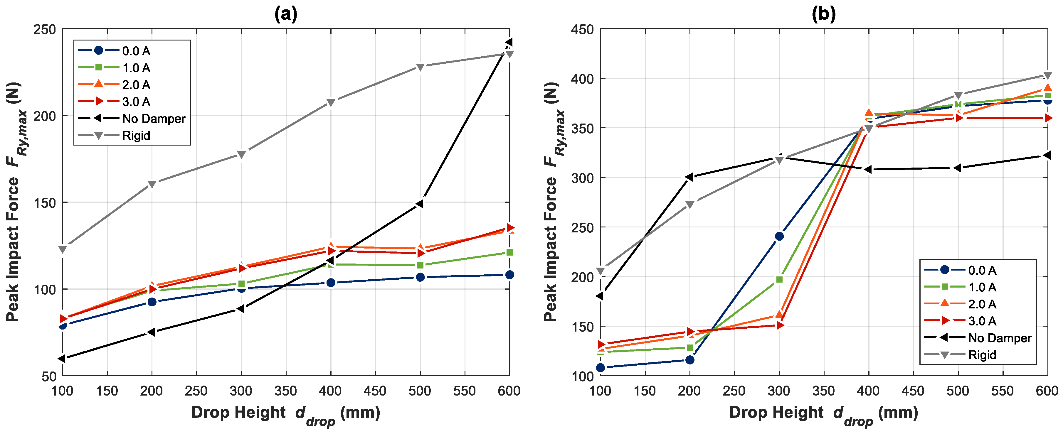
To provide a good indication of impact protection performance for the passive control modes, Figure 9 includes the peak impact force F R y , m a x for all tests. Considering the low mass tests, Figure 9a shows that with the exception of the 100 mm to 400 mm drop height range, the passive control modes resulted in lower peak impact forces than the very soft no damper mode and very stiff rigid mode. With the 0 A current always resulting in the minimum peak impact force for the passive control modes, both 0 A and 1 A also outperformed the no damper mode at a 400 mm drop height. Where things vary quite a bit more is for the large mass tests, as summarised in Figure 9b. Being mindful of the y -axis scale, once again, the impact forces recorded here readily surpassed those of the lower mass tests. It is also clear that a transition occurred for the passive control modes between the 200 mm and 400 mm drop heights, corresponding to where ground collisions started to occur in these tests as the leg began to stroke out. Beyond 200 mm drop heights with a mass of 4.60 kg or more, the leg’s stiffness and damping can therefore be considered insufficient to cushion impacts and prevent collision.

6. Impact Force Control

6.1. Controller Development

With high impact loads potentially putting legged robots and adjacent hardware at risk, a reasonable goal for the control of the MRVSAL-II during impact loading is to minimise peak impact force. Based on observations during the passive control tests, it was found that for many cases, 0 A or other low currents outperformed the 3 A current, indicating lower stiffness and higher damping were beneficial. This is quite reasonable, given a softer leg would require more travel and a greater period to reach its maximum deflection. Coupled with a larger, yet moderate level of damping, this would allow for the dissipation of impact energy at a high rate without causing excessive loading. In stark contrast, when leg deflection exceeded the range the leg was designed to be capable of accommodating, collision of the upper leg segment with the ground caused substantially higher forces for the leg when softer. Thus, there is a trade-off: a lower stiffness leg will reduce impact force, but only for a certain level of deflection; a higher stiffness is required to protect the leg from deflecting beyond its functional range, but otherwise will result in greater impact forces. The key parameter which dictates how far the leg will travel, assuming a constant level of damping with leg deflection, is the vertical kinetic energy E K y of the leg during impact. Making the reasonable assumption that energy is conserved while the leg and platform falls, the gravitational potential energy E P of the leg becomes the kinetic energy, i.e.,
E K y ( t = 0   s ) = E P ( t = 0   s ) = m t o t a l g d d r o p           [ J ] ,
with a corresponding impact velocity v i m p a c t of:
v i m p a c t = v C O M y ( t = 0   s ) = 2 g d d r o p           [ m / s ] .
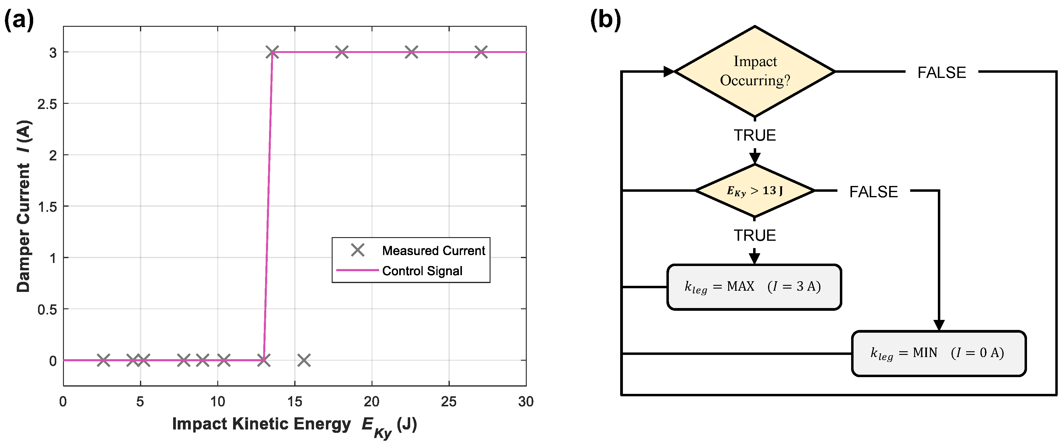
Based on the passive control tests, Equation (1) was applied to convert the drop heights and platform masses into their corresponding kinetic energies at the moment of impact. Following the peak impact forces, the corresponding current which obtained the minimum force was then plotted in Figure 10a. With the assumptions made, one data point conflicts as the leg did not collide during the low mass 600 mm drop for 0 A current. With this one exception, there was a clear transition observed at 13 J of vertical kinetic energy, below which the leg current should be 0 A and above which the leg current should 3 A. Given the near immediate transition within the recorded data, there are essentially binary states the leg should operate in to minimise impact force. This is illustrated in the figure by the solid line through the data, representing the damper current control signal that should correspond to measured kinetic energy at the moment of impact. Based on this concept, Figure 10b shows the process flow diagram for the adopted control algorithm, assuming sensory data have indicated an impact is imminent.

6.2. Experimental Results

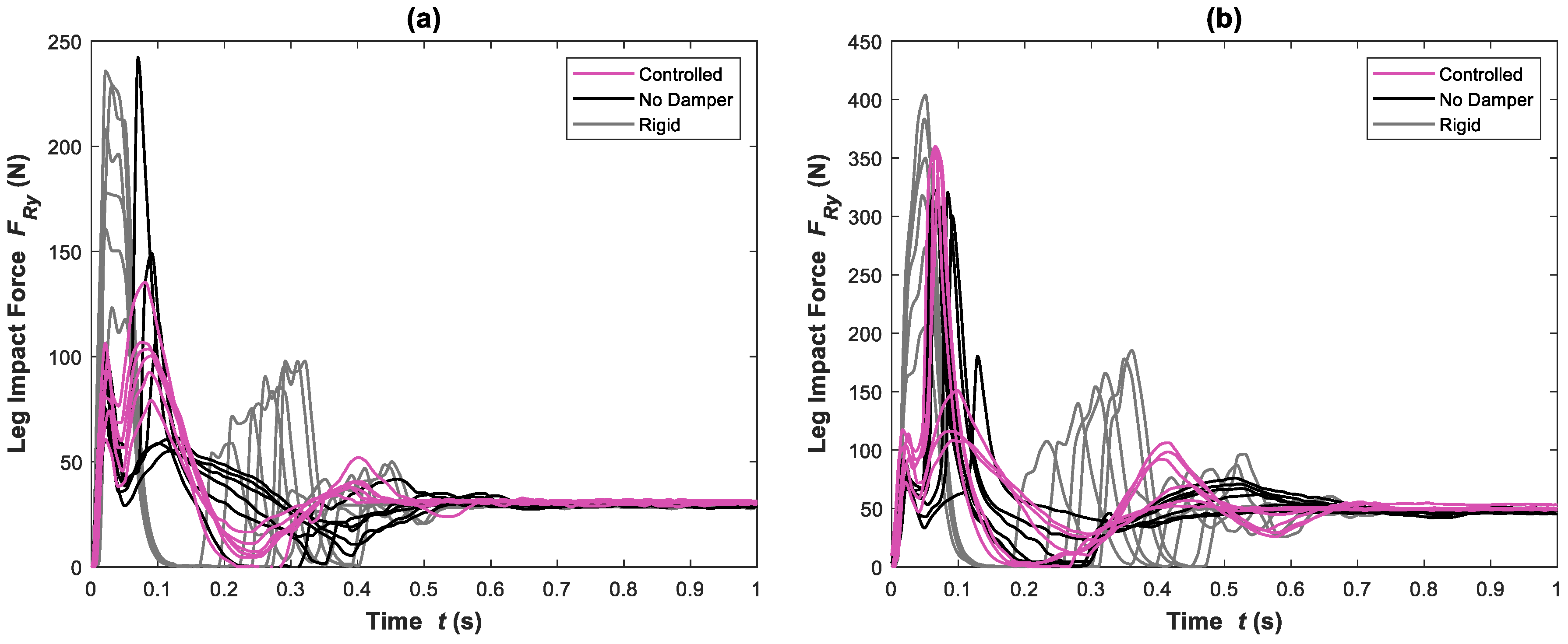
Based on the adopted control algorithm, additional impact tests were conducted for both 2.65 kg and 4.60 kg total falling masses. The impact forces recorded during these tests at all drop heights from 100 mm to 600 mm are presented in Figure 11, along with those from the no damper and rigid cases. This visually captures the behaviour quite well, showing that for a lower fall mass, as in Figure 11a, the controlled MRVSAL-II was able to operate within a tight range of impact forces from 79.2 N to 135 N. In contrast, the rigid leg always resulted in excessive impact forces, ranging from 123 N to 236 N. While the no damper case initially led to smaller impact forces, there was substantial variation due to frequent ground collisions, with a range of 59.9 N to 242 N. For the larger mass scenario, included in Figure 11b, the rigid leg scenario had a range of 206 N to 404 N, with the no damper case varying between 180 N and 322 N. Initially resulting in the lowest impact force for these tests, the controlled mode had a range of 108 N to 360 N. While this did eventually exceed the no damper case, as anticipated from passive tests, the overall improvement in performance here is still evident. This is better understood through the percentage reduction in impact force when comparing the controlled mode to both the no damper and rigid modes, as in Figure 12. Despite some cases where the absence of the damper showed lower impact force, for the 2.65 kg mass in Figure 12a, we found general improvement through control of the MRVSAL-II. When compared, this results in up to 53.2% improvement over the rigid leg, and up to 44.1% improvement over the leg with no damper. For the 4.60 kg mass in Figure 12b, in most cases, the controller offered improvement, with up to 61.4% reduction in peak impact force over the no damper case, and up to 57.5% reduction over the rigid case.
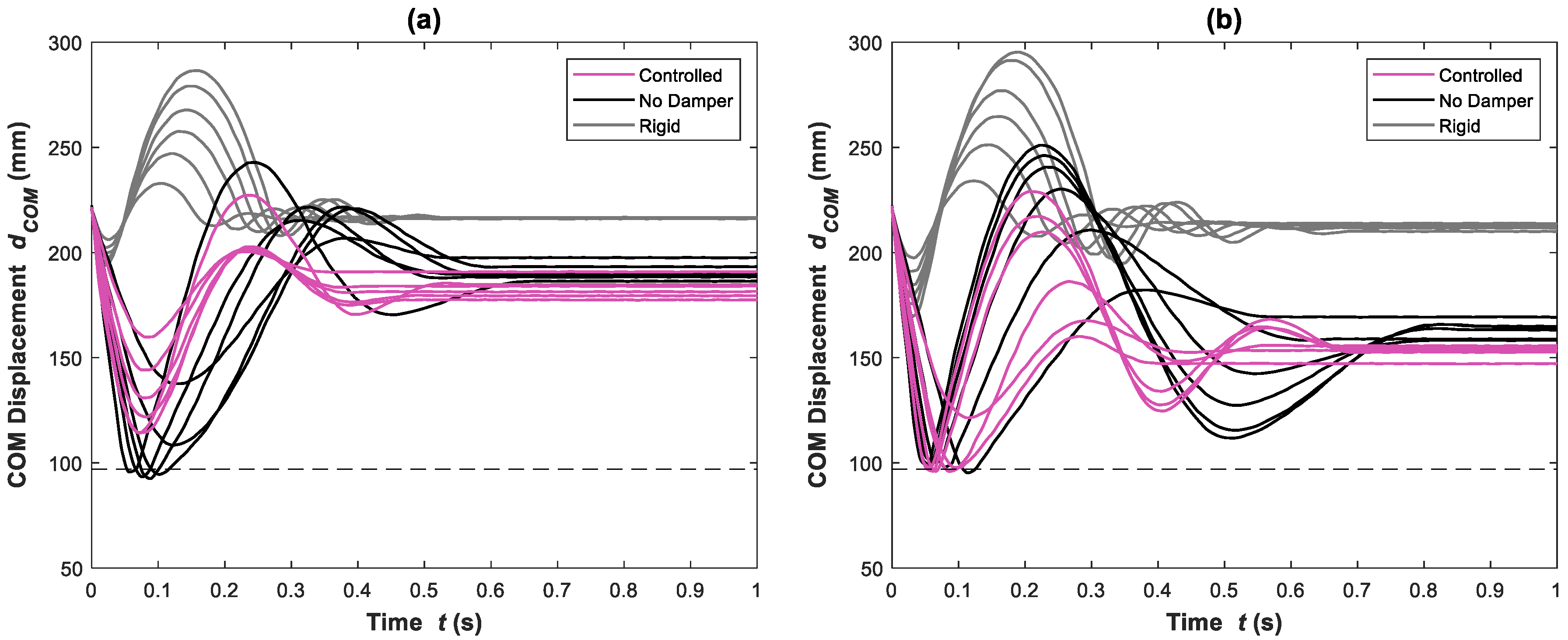
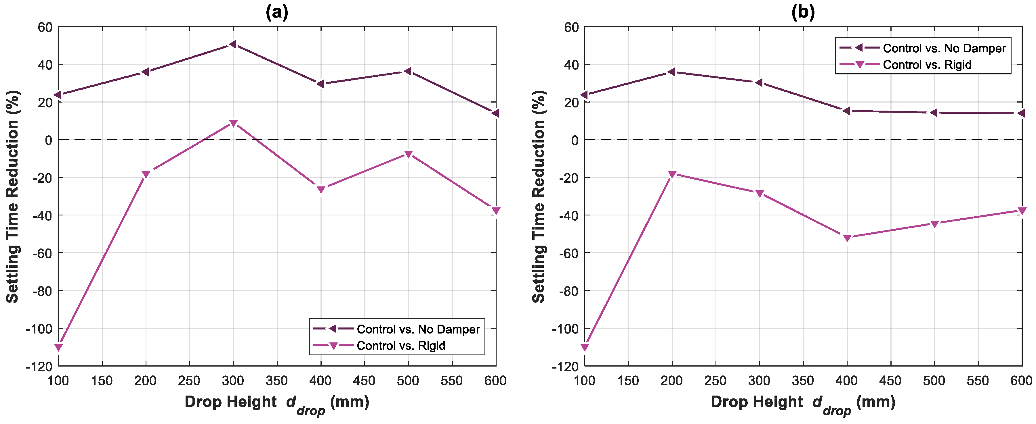
Although not the direct intent of the controller, it is also of interest to compare the displacement of the leg against the rigid and no damper cases, with the corresponding displacement of Figure 11 included in Figure 13. Here we can see that similar to the impact force, the COM displacement of the controlled mode fell within a reasonably tight band when compared with the other modes. The controlled mode also most seldomly experienced bouncing following a collision. Comparing the settling time between the modes, as included in Figure 14, somewhat of a compromise was found, given the rigid leg experienced shorter settling times and higher impact forces, while the no damper leg experienced high settling times and sometimes lower impact forces. For the 2.65 kg mass, included in Figure 14a, the controller resulted in a maximum improvement in settling time over the no damper leg of 50.6%, and 9.16% over the rigid leg. For the 4.60 kg mass, shown in Figure 14b, we found improvement by up to 35.9% over the no damper case and at best a 18.0% increase in settling time when compared with the rigid leg, as indicated by the negative percentage here.

7. Conclusions

As it is an important requirement for legged robots, such as biological legged locomotors, to protect themselves against high impact forces, the MRVSAL-II was put through a series of impact loading experiments within this study. Drop-testing experiments were conducted with the leg for various drop heights ranging from 100 mm to 600 mm, with different payload masses. It was established that while lower stiffness and higher damping could lead to lower impact forces and greater rates of energy dissipation, respectively, optimal control would also protect the leg from deflecting beyond its functional range. Compared with an identical rigid leg with higher damping, up 57.5% reduction in impact force was achieved and 61.4% reduction was achieved over a softer leg with lower damping.

Author Contributions

Conceptualization, M.D.C. and S.S.; methodology, M.D.C. and S.S.; software, M.D.C.; validation, M.D.C., L.D. and S.S.; formal analysis, M.D.C. and L.D.; investigation, M.D.C.; resources, L.D. and W.L.; data curation, M.D.C. and S.S.; writing—original draft preparation, M.D.C.; writing—review and editing, M.D.C. and S.S.; visualization, M.D.C.; supervision, W.L., S.S. and S.Z.; project administration, W.L. and S.Z.; funding acquisition, W.L. and H.D. All authors have read and agreed to the published version of the manuscript.

Funding

This research was supported by the Australian Research Council Linkage Grant (LP190100603) and has been conducted with the support of the Australian Government Research Training Program Scholarship.

Data Availability Statement

Not applicable.

Conflicts of Interest

The authors declare no conflict of interest.

References

  1. Dickinson, M.H.; Farley, C.T.; Full, R.J.; Koehl, M.A.R.; Kram, R.; Lehman, S. How animals move: An integrative view. Science 2000, 288, 100–106. [Google Scholar] [CrossRef]
  2. Farley, C.T.; Houdijk, H.H.P.; Van Strien, C.; Louie, M. Mechanism of leg stiffness adjustment for hopping on surfaces of different stiffnesses. J. Appl. Physiol. 1998, 85, 1044–1055. [Google Scholar] [CrossRef]
  3. Devita, P.; Skelly, W.A. Effect of landing stiffness on joint kinetics and energetics in the lower extremity. Med. Sci. Sport. Exerc. 1992, 24, 108–115. [Google Scholar] [CrossRef]
  4. Roy, M.; Tobias, S.; Reinhard, B. Muscle Preactivation Control: Simulation of Ankle Joint Adjustments at Touchdown During Running on Uneven Ground. J. Appl. Biomech. 2012, 28, 718–725. [Google Scholar] [CrossRef]
  5. Dyhre-Poulsen, P.; Simonsen, E.B.; Voigt, M. Dynamic control of muscle stiffness and H reflex modulation during hopping and jumping in man. J. Physiol. 1991, 437, 287–304. [Google Scholar] [CrossRef]
  6. Müller, R.; Ernst, M.; Blickhan, R. Leg adjustments during running across visible and camouflaged incidental changes in ground level. J. Exp. Biol. 2012, 215, 3072. [Google Scholar] [CrossRef]
  7. Grimmer, S.; Ernst, M.; Günther, M.; Blickhan, R. Running on uneven ground: Leg adjustment to vertical steps and self-stability. J. Exp. Biol. 2008, 211, 2989. [Google Scholar] [CrossRef] [PubMed]
  8. Müller, R.; Birn-Jeffery, A.V.; Blum, Y. Human and avian running on uneven ground: A model-based comparison. J. R. Soc. Interface 2016, 13, 20160529. [Google Scholar] [CrossRef]
  9. Müller, R.; Blickhan, R. Running on uneven ground: Leg adjustments to altered ground level. Hum. Mov. Sci. 2010, 29, 578–589. [Google Scholar] [CrossRef] [PubMed]
  10. Clites, T.R.; Arnold, A.S.; Singh, N.M.; Kline, E.; Chen, H.; Tugman, C.; Billadeau, B.; Biewener, A.A.; Herr, H.M. Goats decrease hindlimb stiffness when walking over compliant surfaces. J. Exp. Biol. 2019, 222, jeb198325. [Google Scholar] [CrossRef] [Green Version]
  11. Moritz, C.T.; Farley, C.T. Passive dynamics change leg mechanics for an unexpected surface during human hopping. J. Appl. Physiol. 2004, 97, 1313–1322. [Google Scholar] [CrossRef]
  12. Moritz, C.T.; Greene, S.M.; Farley, C.T. Neuromuscular changes for hopping on a range of damped surfaces. J. Appl. Physiol. 2004, 96, 1996–2004. [Google Scholar] [CrossRef] [PubMed]
  13. Jill, L.M.-G. Kinematics and Impulse Characteristics of Drop Landings from Three Heights. Int. J. Sport Biomech. 1991, 7, 201–224. [Google Scholar] [CrossRef]
  14. Ozgüven, H.N.; Berme, N. An experimental and analytical study of impact forces during human jumping. J. Biomech. 1988, 21, 1061–1066. [Google Scholar] [CrossRef]
  15. Mizrahi, J.; Susak, Z. Analysis of parameters affecting impact force attenuation during landing in human vertical free fall. Eng. Med. 1982, 11, 141–147. [Google Scholar] [CrossRef]
  16. Hackney, J.M.; Clay, R.L.; James, M. Force-displacement differences in the lower extremities of young healthy adults between drop jumps and drop landings. Hum. Mov. Sci. 2016, 49, 79–86. [Google Scholar] [CrossRef] [PubMed]
  17. Decker, M.J.; Torry, M.R.; Wyland, D.J.; Sterett, W.I.; Richard Steadman, J. Gender differences in lower extremity kinematics, kinetics and energy absorption during landing. Clin. Biomech. 2003, 18, 662–669. [Google Scholar] [CrossRef] [PubMed]
  18. Zhang, S.N.; Bates, B.T.; Dufek, J.S. Contributions of lower extremity joints to energy dissipation during landings. Med. Sci. Sport. Exerc. 2000, 32, 812–819. [Google Scholar] [CrossRef]
  19. Podraza, J.T.; White, S.C. Effect of knee flexion angle on ground reaction forces, knee moments and muscle co-contraction during an impact-like deceleration landing: Implications for the non-contact mechanism of ACL injury. Knee 2010, 17, 291–295. [Google Scholar] [CrossRef]
  20. Whitting, J.W.; Steele, J.R.; McGhee, D.E.; Munro, B.J. Effects of passive ankle dorsiflexion stiffness on ankle mechanics during drop landings. J. Sci. Med. Sport 2012, 15, 468–473. [Google Scholar] [CrossRef]
  21. Batterbee, D.C.; Sims, N.D.; Stanway, R.; Wolejsza, Z. Magnetorheological landing gear: 1. A design methodology. Smart Mater. Struct. 2007, 16, 2429–2440. [Google Scholar] [CrossRef]
  22. Choi, Y.-T.; Wereley, N.M. Shock Isolation Systems Using Magnetorheological Dampers. J. Vib. Acoust. 2008, 130, 024503. [Google Scholar] [CrossRef]
  23. Choi, Y.-T.; Wereley, N.M. Biodynamic Response Mitigation to Shock Loads Using Magnetorheological Helicopter Crew Seat Suspensions. J. Aircr. 2005, 42, 1288–1295. [Google Scholar] [CrossRef]
  24. Choi, Y.-T.; Wereley, N.M. Vibration Control of a Landing Gear System Featuring Electrorheological/Magnetorheological Fluids. J. Aircr. 2003, 40, 432–439. [Google Scholar] [CrossRef]
  25. Robinson, D.W.; Pratt, J.E.; Paluska, D.J.; Pratt, G.A. Series elastic actuator development for a biomimetic walking robot. In Proceedings of the 1999 IEEE/ASME International Conference on Advanced Intelligent Mechatronics (Cat. No.99TH8399), Atlanta, GA, USA, 19–23 September 1999; pp. 561–568. [Google Scholar]
  26. Hutter, M.; Remy, C.D.; Hoepflinger, M.A.; Siegwart, R. Efficient and Versatile Locomotion With Highly Compliant Legs. IEEE/ASME Trans. Mechatron. 2013, 18, 449–458. [Google Scholar] [CrossRef]
  27. Vanderborght, B.; Albu-Schaeffer, A.; Bicchi, A.; Burdet, E.; Caldwell, D.G.; Carloni, R.; Catalano, M.; Eiberger, O.; Friedl, W.; Ganesh, G.; et al. Variable impedance actuators: A review. Robot. Auton. Syst. 2013, 61, 1601–1614. [Google Scholar] [CrossRef]
  28. Wolf, S.; Grioli, G.; Eiberger, O.; Friedl, W.; Grebenstein, M.; Hoppner, H.; Burdet, E.; Caldwell, D.G.; Carloni, R.; Catalano, M.G.; et al. Variable Stiffness Actuators: Review on Design and Components. IEEE/ASME Trans. Mechatron. 2016, 21, 2418–2430. [Google Scholar] [CrossRef]
  29. Christie, M.D.; Sun, S.; Deng, L.; Du, H.; Zhang, S.W.; Li, W.H. Real-time adaptive leg-stiffness for roll compensation via magnetorheological control in a legged robot. Smart Mater. Struct. 2022, 31, 045003. [Google Scholar] [CrossRef]
  30. Christie, M.D.; Sun, S.; Ning, D.H.; Du, H.; Zhang, S.W.; Li, W.H. A highly stiffness-adjustable robot leg for enhancing locomotive performance. Mech. Syst. Signal Process. 2019, 126, 458–468. [Google Scholar] [CrossRef]
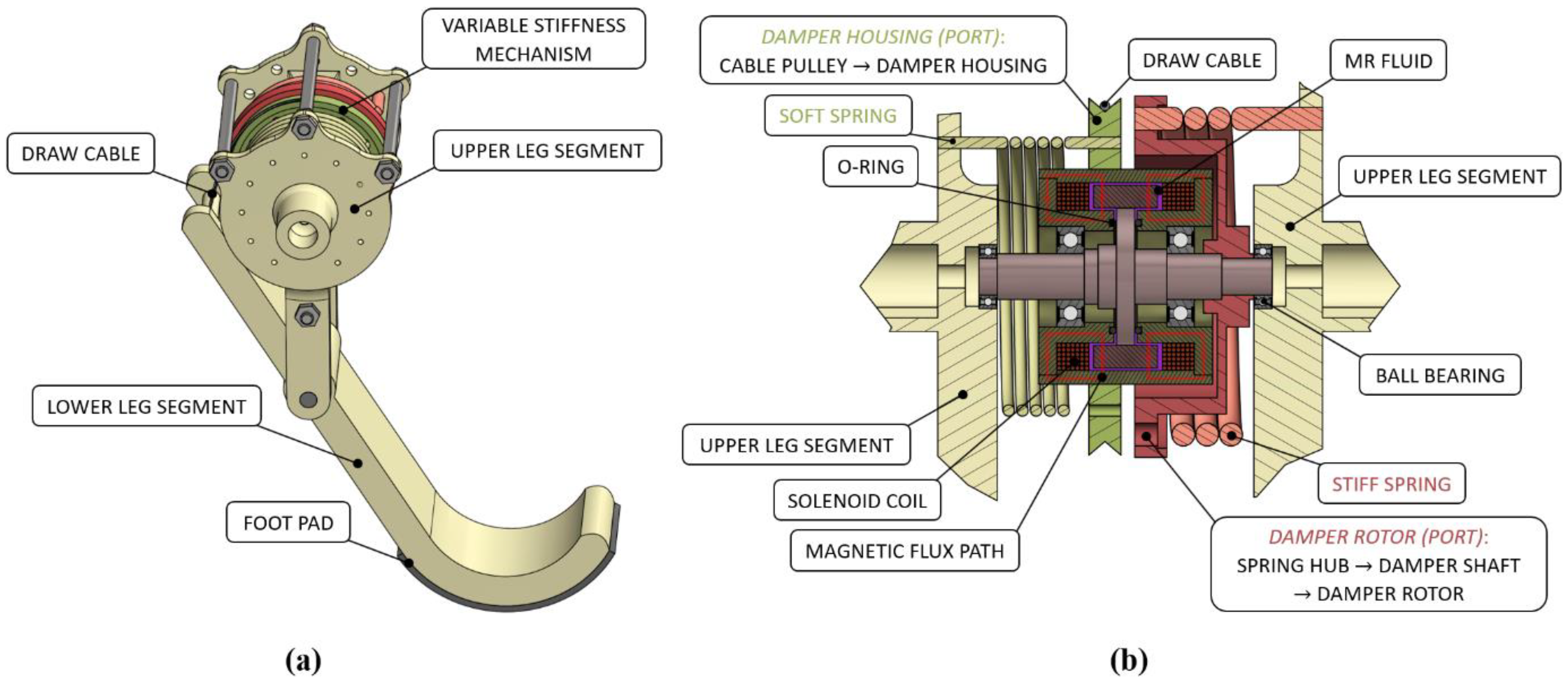
Figure 1. CAD model of (a) MRVSAL, and (b) the contained variable stiffness mechanism.
Machines 11 00236 g001
Figure 2. Impact loading experimental setup (a) layout and (b) control system.
Machines 11 00236 g002
Figure 3. Impact loading free body diagram at (a) the moment of impact and (b) during impact.
Machines 11 00236 g003
Figure 4. COM displacement for impact tests with a 2.65 kg total mass for drop heights of (a) 100 mm, (b) 200 mm, (c) 300 mm, (d) 400 mm, (e) 500 mm, and (f) 600 mm.
Machines 11 00236 g004
Figure 5. COM displacement for impact tests with a 4.60 kg total mass for drop heights of (a) 100 mm, (b) 200 mm, (c) 300 mm, (d) 400 mm, (e) 500 mm, and (f) 600 mm.
Machines 11 00236 g005
Figure 6. Settling time for impact tests with total masses of (a) 2.65 kg and (b) 4.60 kg.
Machines 11 00236 g006
Figure 7. Leg impact force for impact tests with a 2.65 kg total mass for drop heights of (a) 100 mm, (b) 200 mm, (c) 300 mm, (d) 400 mm, (e) 500 mm, and (f) 600 mm.
Machines 11 00236 g007
Figure 8. Leg impact force for impact tests with a 4.60 kg total mass for drop heights of (a) 100 mm, (b) 200 mm, (c) 300 mm, (d) 400 mm, (e) 500 mm, and (f) 600 mm.
Machines 11 00236 g008
Figure 9. Peak impact force for impact tests with masses of (a) 2.65 kg, and (b) 4.60 kg.
Machines 11 00236 g009
Figure 10. Impact force controller: (a) damper control signal, and (b) process flow diagram.
Machines 11 00236 g010
Figure 11. Controlled impact force for impact tests at all drop heights with total masses of (a) 2.65 kg and (b) 4.60 kg.
Machines 11 00236 g011
Figure 12. Controller improvement in peak impact force for impact tests with total masses of (a) 2.65 kg and (b) 4.60 kg.
Machines 11 00236 g012
Figure 13. Controlled COM displacement for impact tests at all drop heights with total masses of (a) 2.65 kg and (b) 4.60 kg.
Machines 11 00236 g013
Figure 14. Controller improvement in settling time for impact tests with total masses of (a) 2.65 kg and (b) 4.60 kg.
Machines 11 00236 g014
Disclaimer/Publisher’s Note: The statements, opinions and data contained in all publications are solely those of the individual author(s) and contributor(s) and not of MDPI and/or the editor(s). MDPI and/or the editor(s) disclaim responsibility for any injury to people or property resulting from any ideas, methods, instructions or products referred to in the content.