
A Novel Auxiliary Excretion Approach to a Lavatory Robot with Safety and Robustness


Abstract
:1. Introduction
- (1)
- The ALR with remote awakening, autonomous movement, and security monitoring functions was developed. It provides a new solution for auxiliary excretion in a narrow indoor space to assist the elderly and the disabled.
- (2)
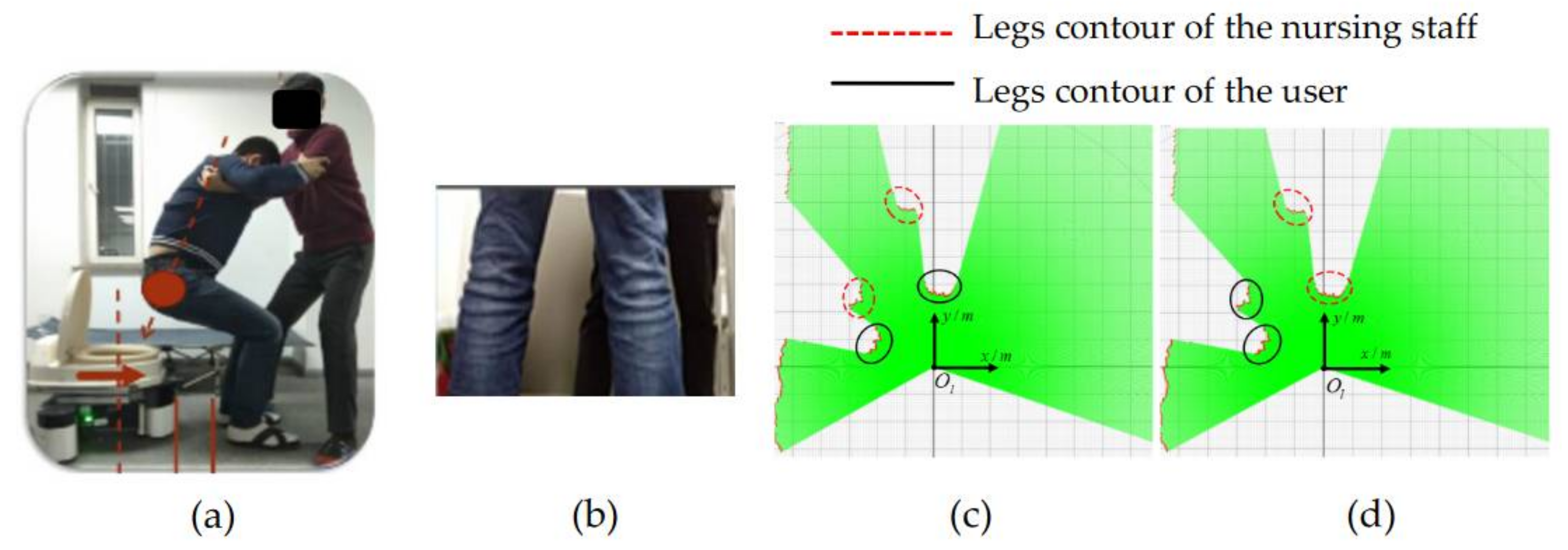
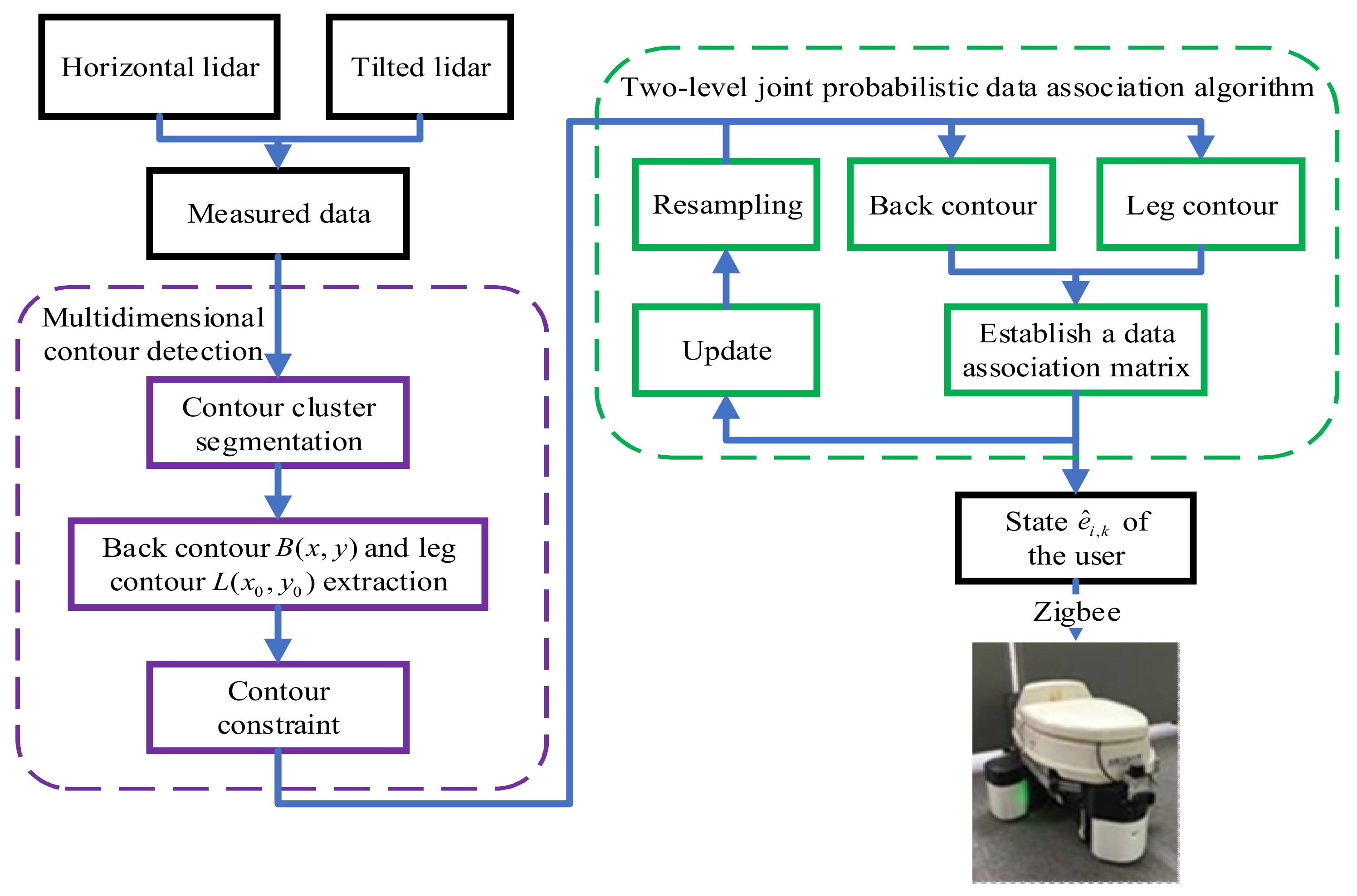
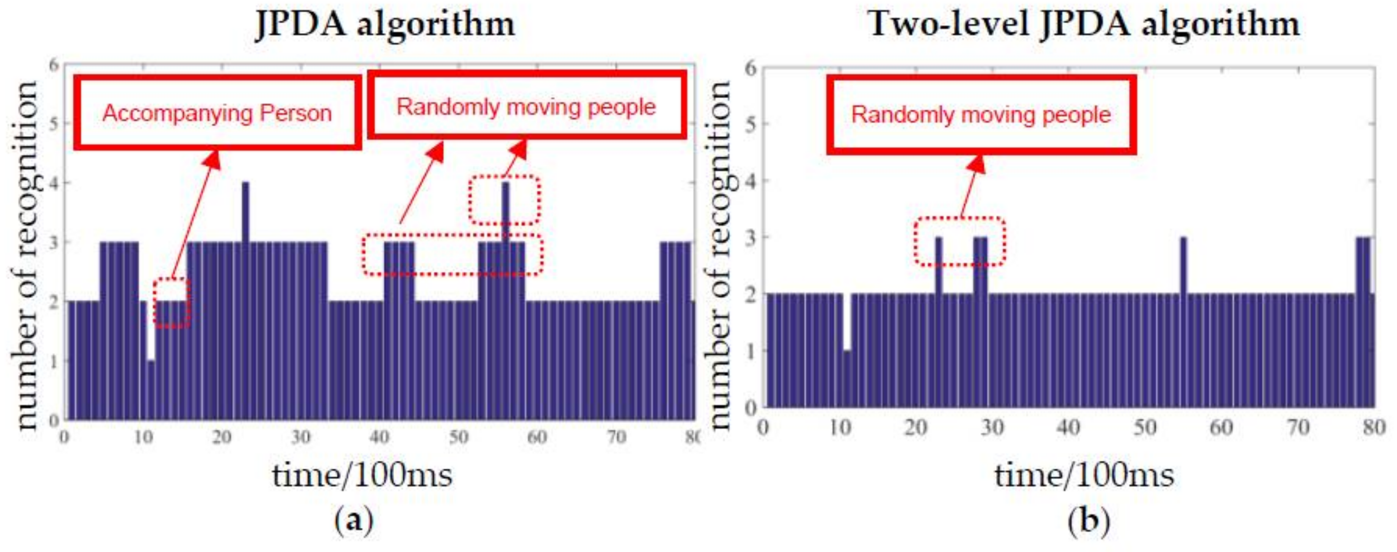
- A two-level joint probabilistic data association algorithm (JPDA) based on a multi-constraint contour was proposed. Under the complex background of the dynamic environment interference and limb occlusion of the nursing staff, this method can accurately recognize the leg contour and the user’s dynamic posture. It provides a high-robust solution to solve limb confusion, large-area trunk occlusion, and complex environment interference.
- (3)
- The robot, integrated with our proposed algorithm, provided a comfortable and convenient approach for auxiliary execution. The whole system lightened the psychological burden and improved safety during human–robot interaction. This approach can be applied to similar scenarios of helping the elderly and the disabled.
2. Materials and Methods
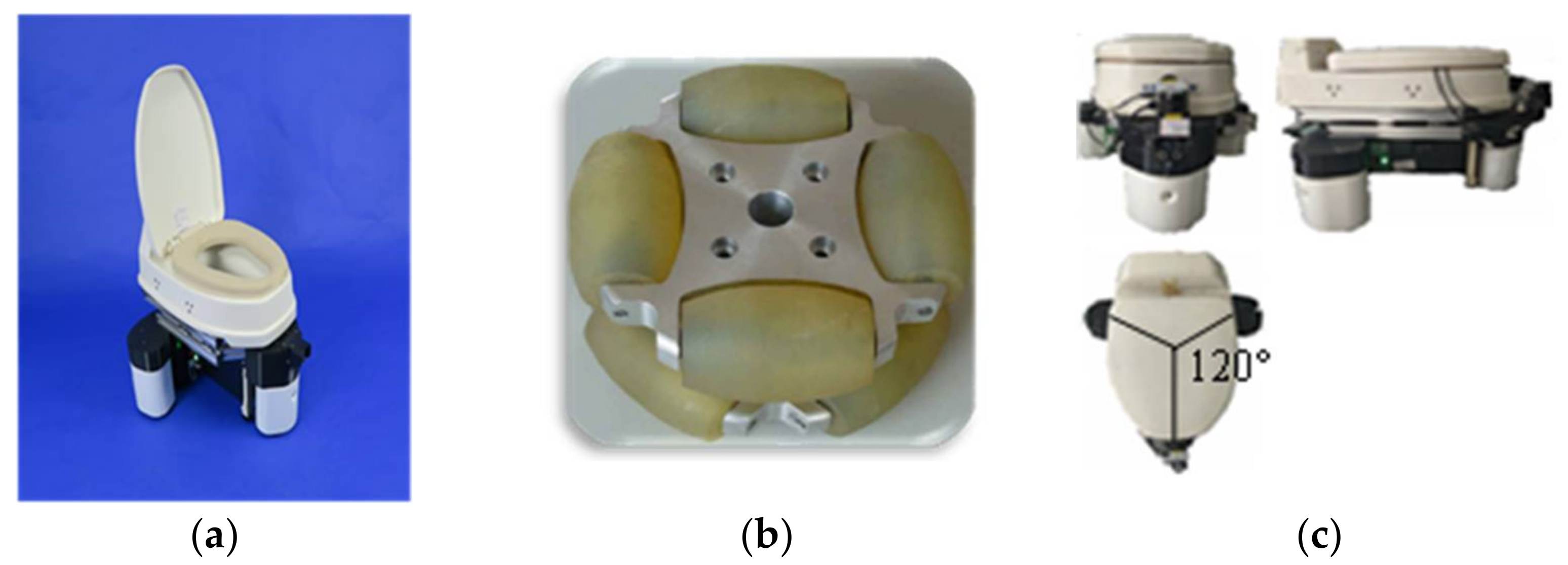
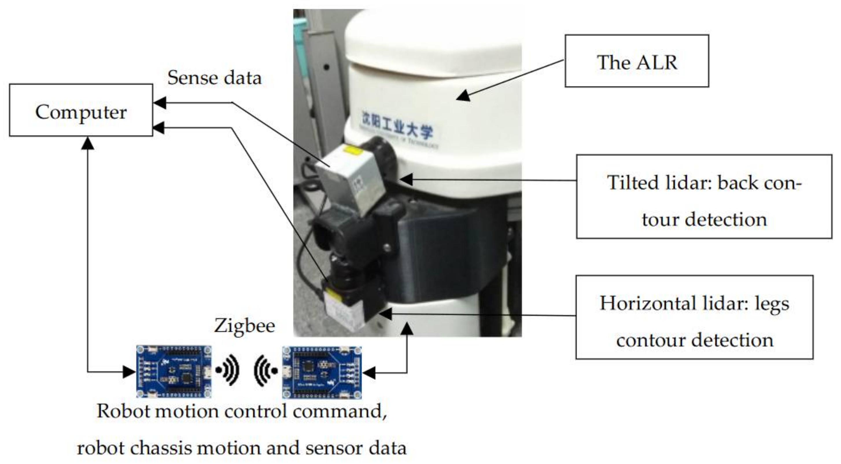
2.1. Auxiliary Lavatory Robot
2.2. Posture Recognition System
2.3. Posture Recognition System
3. Two-Level JPDA Based on Multi-Constraint Contour
3.1. Multidimensional Contour Recognition Algorithm
- (1)
- Contour cluster segmentation
- (2)
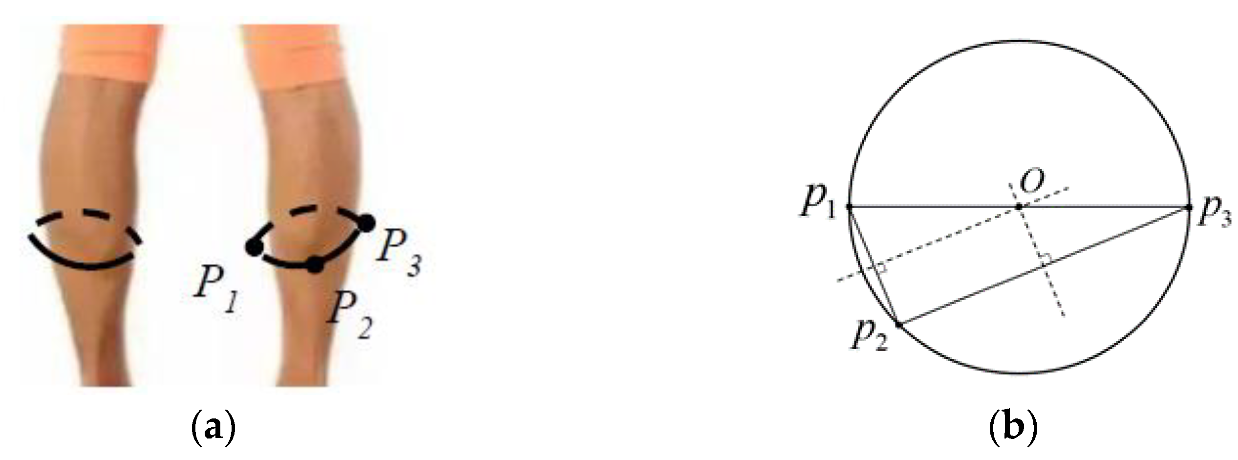
- Leg contour extraction
- (3)
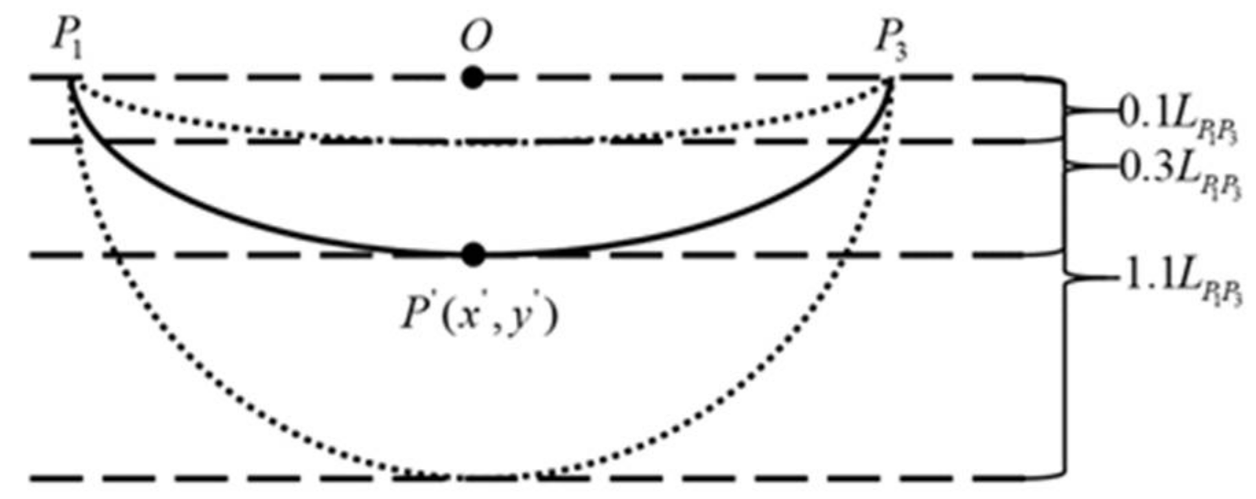
- Contour constraint
- (4)
- Back contour detection
| Algorithm 1: Multidimensional contour recognition. | |
| Require: | |
| Data of horizontal lidar and horizontal lidar: | |
| 1: | while do |
| 2: | for do |
| 3: | |
| 4: | |
| 5: | end for |
| 6: | for do |
| 7: | |
| 8: | |
| 9: | |
| 10: | if then |
| 11: | |
| 12: | for do |
| 13: | |
| 14: | |
| 15: | end for |
| 16: | |
| 17: | |
| 18: | end if |
| 19: | end for |
| 20: | for do |
| 21: | |
| 22: | |
| 23: | for do |
| 24: | if then |
| 25: | |
| 26: | end if |
| 27: | end for |
| 28: | end for |
| 29: | end while |
| 30: | return |
3.2. Two-Level JPDA
| Algorithm 2: Two-level JPDA. | |
| Require: | |
| Bottom-level parameter: | |
| Top-level parameter: | |
| 1: | while do |
| 2: | |
| 3: | |
| 4: | |
| 5: | |
| 6: | if then |
| 7: | return |
| 8: | end if |
| 9: | else |
| 10: | for do |
| 11: | |
| 12: | end for |
| 13: | end else |
| 14: | |
| 15: | end while |
4. Experiment and Analysis
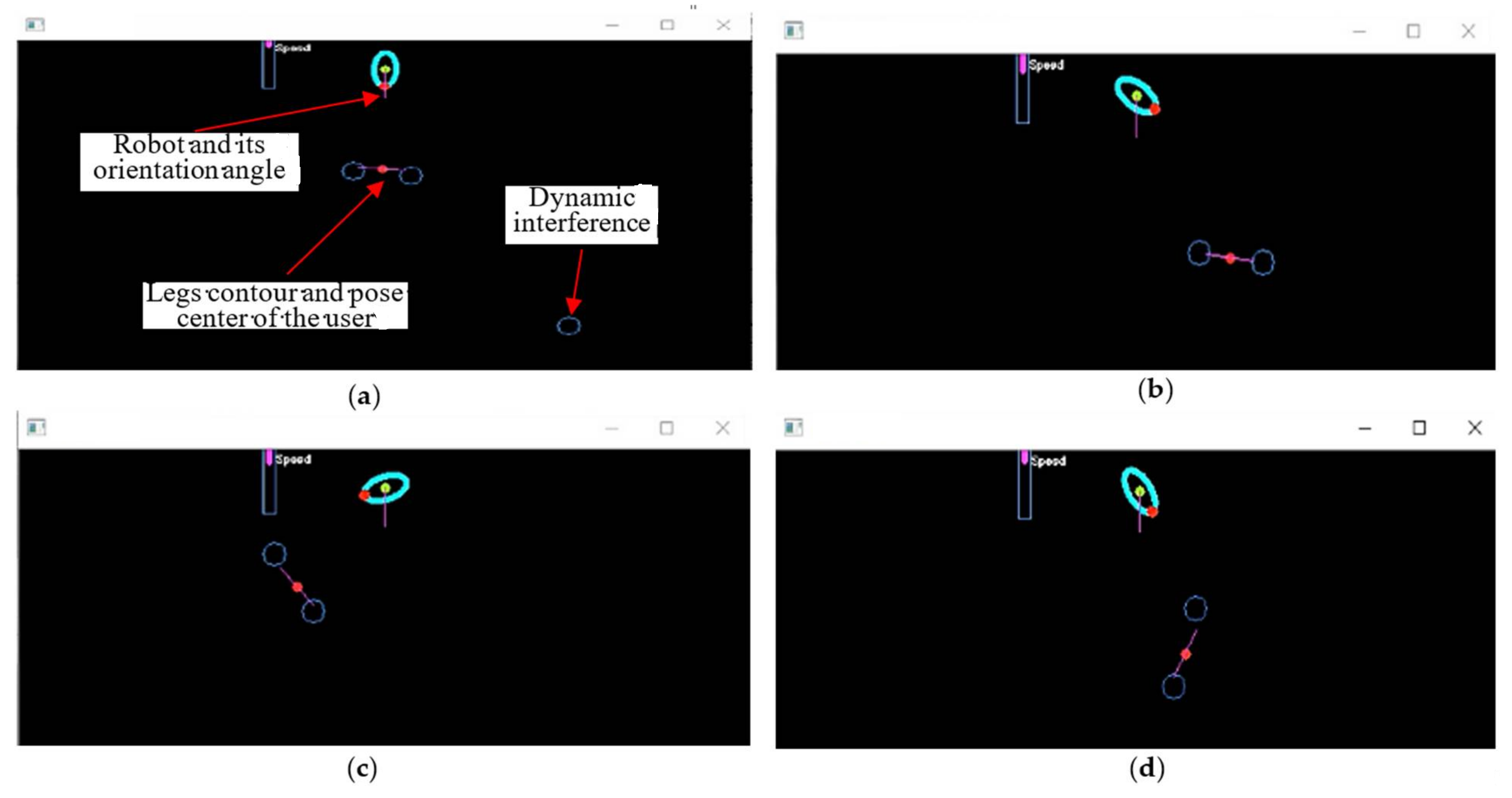
4.1. Leg Target Recognition Experiment
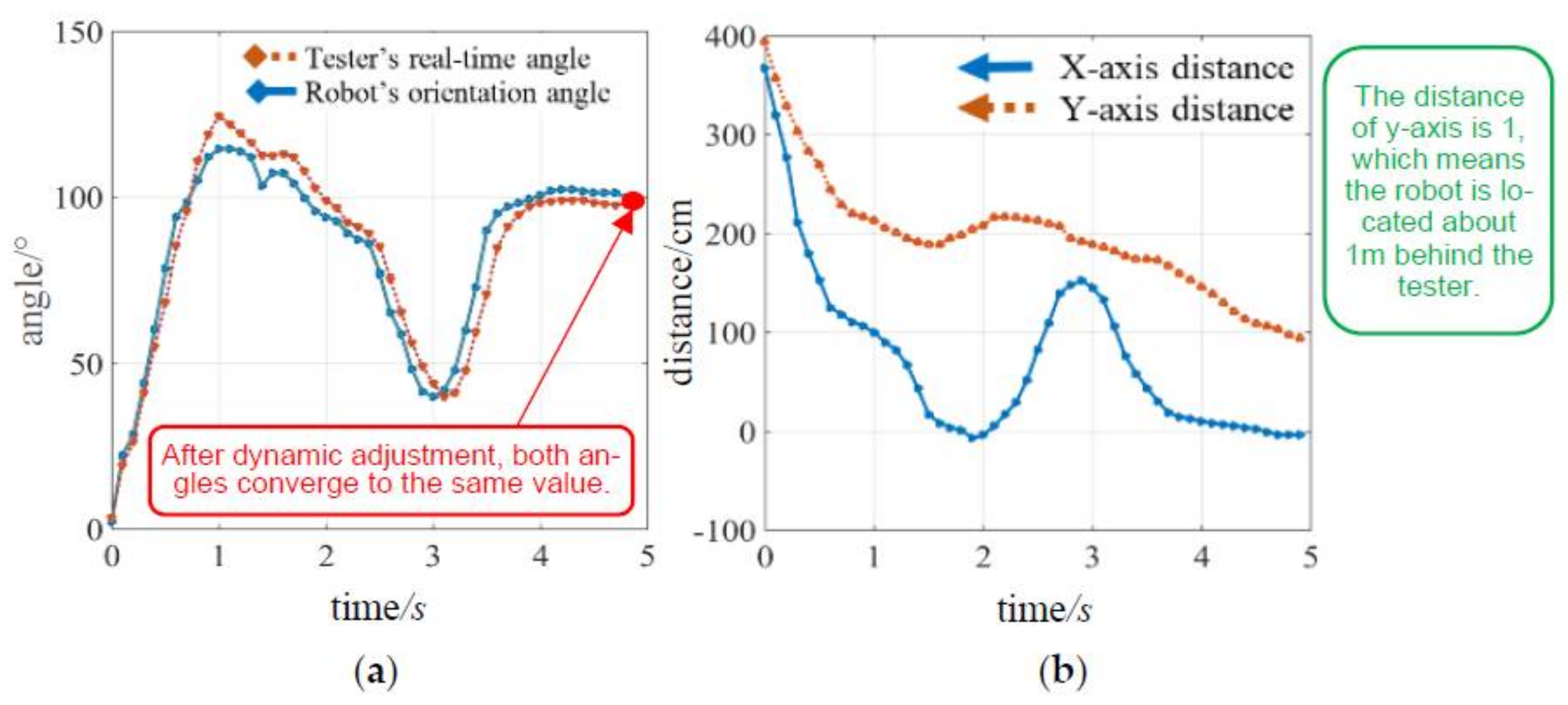
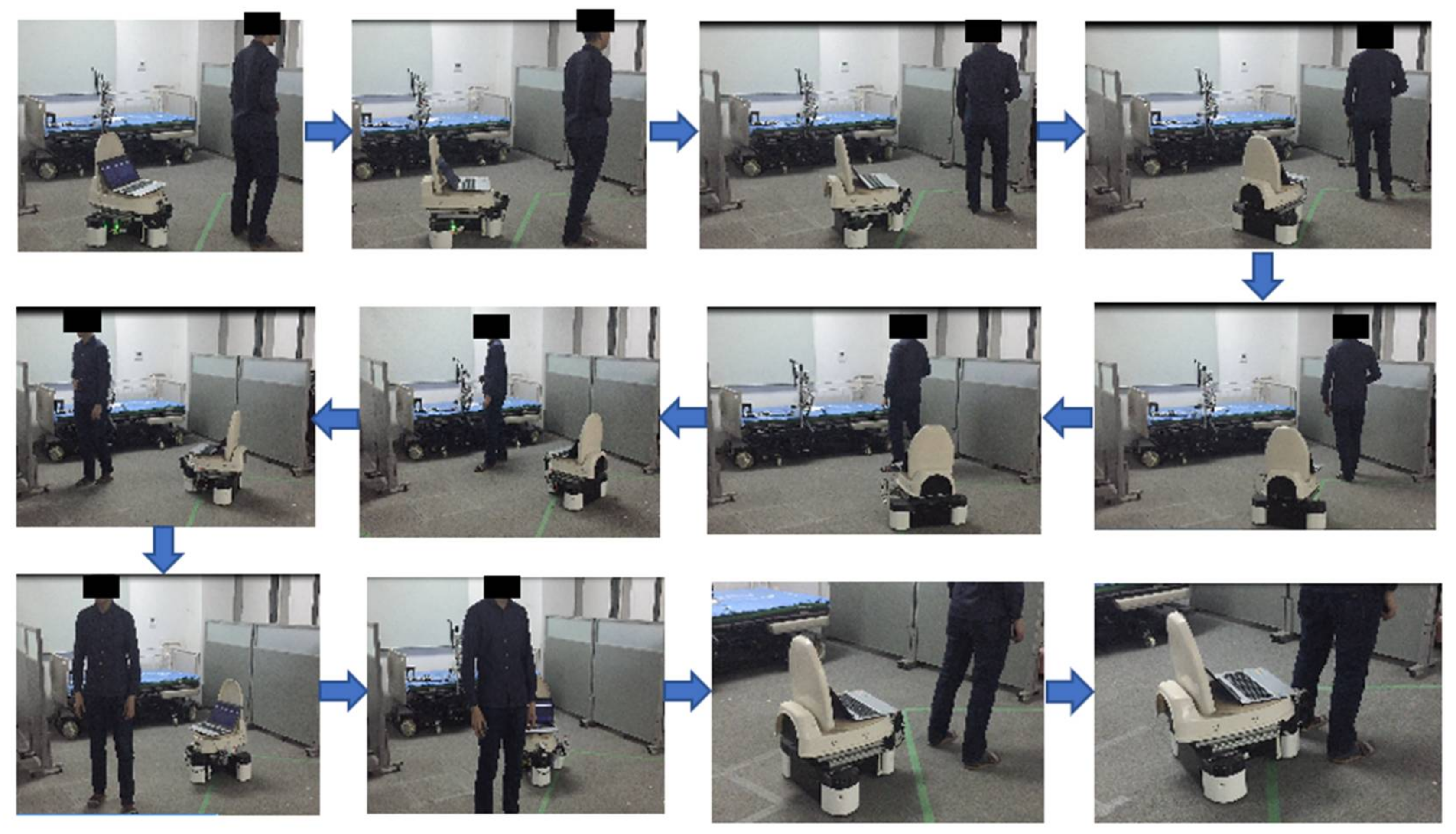
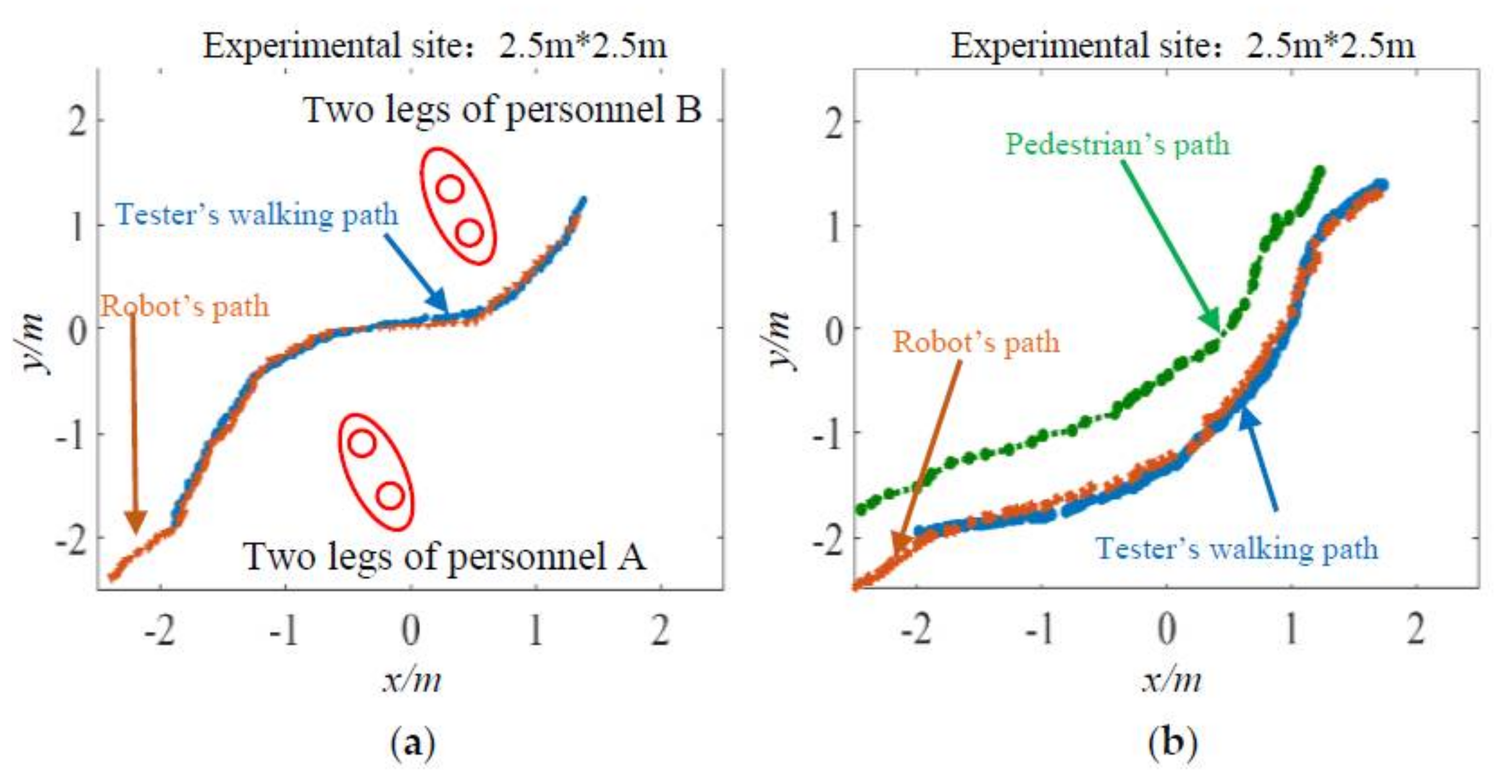
4.2. Path-Tracking Experiment
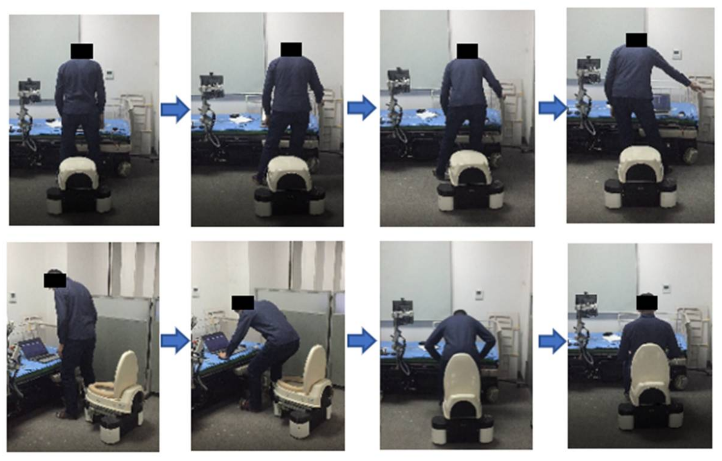
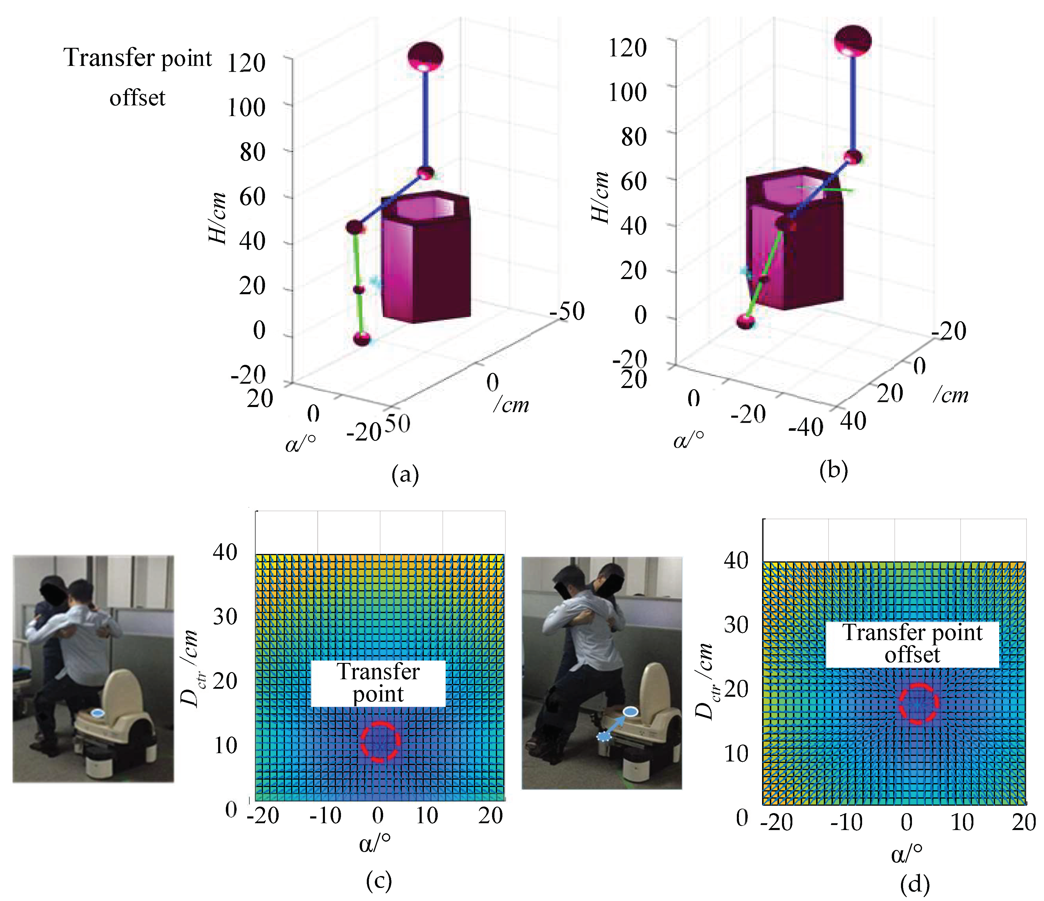
4.3. Auxiliary Excretion Transfer Experiment
- (1)
- Compared to traditional auxiliary lavatory robots, the ALR integrates more functions. First, the ALR has a remote wake-up function so that the user can control the ALR by remote control, which will save the user’s physical strength. Furthermore, the ALR provided the best transfer posture, which can improve the safety of the transfer. Furthermore, the ALR could achieve autonomous navigation and clean the excrement in time, reducing the users’ psychological burden. These functions of the ALR provide a new solution for daily auxiliary excretion.
- (2)
- Compared with the traditional human posture recognition method by using a camera or wearable attitude sensor, the interactive method provided in this paper does not require the user to wear any equipment in advance. Therefore, it is very convenient for the elderly and people with weak motion capability.
- (3)
- Through the method proposed in this paper, the issue of recognizing the limb confusion and the occlusion of surrounding dynamic people was resolved. Because the ALR can accurately identify and track the user’s leg posture, the burden of the nursing staff and the probability of transfer failure are reduced, and the robustness of the human–computer interaction process is improved.
5. Conclusions
Author Contributions
Funding
Institutional Review Board Statement
Informed Consent Statement
Data Availability Statement
Acknowledgments
Conflicts of Interest
References
- Bakhshiev, A.; Smirnova, E.; Musienko, P. Methodological bases of exobalancer design for rehabilitation of people with limited mobility and impaired balance maintenance. J. Afr. Earth Sci. 2015, 12, 201–213. [Google Scholar]
- Zerah, L.; Bihan, K.; Kohler, S.; Mariani, L. Iatrogenesis and neurological manifestations in the elderly. Rev. Neurol. 2020, 176, 710–723. [Google Scholar] [CrossRef] [PubMed]
- Gallego, L.; Losada, A.; Vara, C.; Olazarán, J.; Muñiz, R.; Pillemer, K. Psychosocial predictors of anxiety in nursing home staff. Clin. Gerontol. 2017, 41, 282–292. [Google Scholar] [CrossRef] [PubMed]
- Lee, J.; Gang, M. The moderating effect of communication behavior on nurses’ care burden associated with behavioral and psychological symptoms of dementia. Issues Ment. Health Nurs. 2019, 41, 132–137. [Google Scholar] [CrossRef] [PubMed]
- Lebet, R.; Hasbani, N.; Sisko, M.; Agus, M.; Curley, M. Nurses’ perceptions of workload burden in pediatric critical care. Am. J. Crit. Care 2021, 30, 27–35. [Google Scholar] [CrossRef]
- Zhao, Z.; Li, X.; Lu, C.; Zhang, M.; Wang, Y. Compliant manipulation method for a nursing robot based on physical structure of human limb. Intell. Serv. Robot. Syst 2020, 100, 973–986. [Google Scholar] [CrossRef]
- Mcdonnell, S.; Timmins, F. Subjective burden experienced by nurses when caring for delirious patients. J. Clin. Nurs. 2012, 21, 2488–2498. [Google Scholar] [CrossRef] [PubMed]
- Vichitkraivin, P.; Naenna, T. Factors of healthcare robot adoption by medical staff in Thai government hospitals. Health Technol. 2021, 11, 139–151. [Google Scholar] [CrossRef]
- Liang, J.; Wu, J.; Huang, H.; Xu, W.; Xi, F. Soft sensitive skin for safety control of a nursing robot using proximity and tactile sensors. IEEE Sens. J. 2020, 20, 3822–3830. [Google Scholar] [CrossRef]
- Abubakar, S.; Das, S.; Robinson, C.; Saadatzi, M.; Logsdon, M.; Mitchell, H.; Chlebowy, D.; Popa, D. ARNA, a Service Robot for Nursing Assistance: System Overview and User Acceptability. In Proceedings of the 2020 IEEE 16th International Conference on Automation Science and Engineering, Hong Kong, China, 20–21 August 2020. [Google Scholar]
- Grewal, H.; Matthews, A.; Tea, R.; Contractor, V.; George, K. Sip-and-Puff Autonomous Wheelchair for Individuals with Severe Disabilities. In Proceedings of the 2018 9th IEEE Annual Ubiquitous Computing, Electronics & Mobile Communication Conference, New York, NY, USA, 8–10 November 2018. [Google Scholar]
- Ignacio, G.; Mario, M.; Teresita, M. Smart medical beds in patient-care environments of the twenty-first century: A state-of-art survey. BMC Med. Inf. Decis. Mak. 2018, 18, 63. [Google Scholar]
- Wang, Y.; Wang, S. Development of an excretion care support robot with human cooperative characteristics. In Proceedings of the 2015 37th Annual International Conference of the IEEE Engineering in Medicine and Biology Society, Milan, Italy, 5 November 2015. [Google Scholar]
- Wang, Y.; Wang, S.; Jiang, Y.; Tan, R. Control of an excretion care support robot using digital acceleration control algorithm: Path tracking problem in an indoor environment. J. Syst. Des. Dyn. 2013, 7, 472–487. [Google Scholar] [CrossRef] [Green Version]
- Moudpoklang, J.; Pedchote, C. Line tracking control of royal Thai air force nursing mobile robot using visual feedback. In IOP Conference Series: Materials Science and Engineering; IOP Publishing: Bristol, UK, 2021; Volume 1137, p. 10. [Google Scholar]
- Luo, Z. Systematic innovation of health robotics for aging society—Health renaissance century is coming. Sci. Technol. Rev. 2015, 33, 45–53. [Google Scholar]
- Bae, G.; Kim, S.; Choi, D.; Cho, C.; Lee, S.; Kang, S. Omni-directional Power-Assist-Modular(PAM) Mobile Robot for Total Nursing Service System. In Proceedings of the 2017 14th International Conference on Ubiquitous Robots and Ambient Intelligence, Jeju, Korea, 28 June–1 July 2017. [Google Scholar]
- Pineau, J.; Montemerlo, M.; Pollack, M.; Roy, N.; Thrun, S. Towards robotic assistants in nursing homes: Challenges and results. Rob. Auton. Syst. 2003, 42, 271–281. [Google Scholar] [CrossRef]
- Amalia, N.; Hatta, A.; Koentjoro, S.; Nasution, A.; Puspita, I. Fiber Sensor for Simultaneous Measurement of Heart and Breath Rate on SmartBed. In Proceedings of the 2020 IEEE 8th International Conference on Photonics, Kota Bharu, Malaysia, 12 May–30 June 2020. [Google Scholar]
- Cai, H.; Toft, E.; Hejlesen, O.; Hansen, J.; Oestergaard, C.; Dinesen, B. Health professionals’ user experience of the intelligent bed in patients’ homes. Int. J. Technol. Assess. Health Care 2015, 31, 256–263. [Google Scholar] [CrossRef] [PubMed]
- Gao, H.; Lu, S.; Li, W. The Design of CAN and TCP/IP-based Robotic Multifunctional Nursing Bed. In Proceedings of the 2010 8th World Congress on Intelligent Control and Automation, Jinan, China, 7–9 July 2010. [Google Scholar]
- Lin, T.; Lu, S.; Wei, Z. A Robotic Nursing Bed Design and its Control System. In Proceedings of the 2009 IEEE International Conference on Robotics and Biomimetics, Guilin, China, 19–23 December 2009. [Google Scholar]
- Zhang, T.; Xie, C.; Lin, L. Research on Tele-monitoring System and Control System of Intelligent Nursing Bed Based on Network. In Proceedings of the 2006 6th World Congress on Intelligent Control and Automation, Dalian, China, 21–23 June 2006. [Google Scholar]
- Guo, S.; Zhao, X.; Matsuo, K.; Liu, J.; Mukai, T. Unconstrained detection of the respiratory motions of chest and abdomen in different lying positions using a flexible tactile sensor array. IEEE Sens. J. 2019, 19, 10067–10076. [Google Scholar] [CrossRef]
- Sun, Q.; Cheng, W. Mechanism design and debugging of an intelligent rehabilitation nursing bed. Int. J. Eng. Sci. 2015, 3, 19–21. [Google Scholar]
- Zhang, H.; Sun, H. Study on the parameters of cleaning water jet for nursing bed hips. In IOP Conference Series: Earth and Environmental Science; IOP Publishing: Bristol, UK, 2021; Volume 632, p. 052030. [Google Scholar]
- Chang, H.; Huang, T.; Wong, M.; Ho, L.; Teng, C. How robots help nurses focus on professional task engagement and reduce nurses’ turnover intention. J. Nurs. Scholarsh. 2021, 53, 237–245. [Google Scholar] [CrossRef]
- Zhao, J.; Shen, L.; Yang, C.; Zhang, Z.; Zhao, J. 3D Shape Reconstruction of Human Spine Based on the Attitude Sensor. In Proceedings of the 2019 IEEE 8th Joint International Information Technology and Artificial Intelligence Conference, Chongqing, China, 24–26 May 2019. [Google Scholar]
- Joukov, V.; Bonnet, V.; Karg, M.; Venture, G.; Kulic, D. Rhythmic extended Kalman filter for gait rehabilitation motion estimation and segmentation. IEEE Trans. Neural Syst. Rehabil. Eng. 2018, 26, 407–418. [Google Scholar] [CrossRef]
- Zhu, G.; Wang, Y. Research on human body motion attitude capture and recognition based on multi-sensors. Rev. Tecn. Fac. Ingr. 2017, 32, 775–784. [Google Scholar]
- Shi, C.; Zhang, L.; Hu, W.; Liu, S. Attitude-sensor-aided in-process registration of multi-view surface measurement. Measurement 2011, 44, 663–673. [Google Scholar] [CrossRef]
- Mehralian, M.; Soryani, M. EKFPnP: Extended Kalman filter for camera pose estimation in a sequence of images. IET Image Process. 2020, 14, 3774–3780. [Google Scholar] [CrossRef]
- Rohe, D.P.; Witt, B.L.; Schoenherr, T.F. Predicting 3d motions from single-camera optical test data. Exp. Tech. 2020, 45, 313–327. [Google Scholar] [CrossRef]
- Li, G.; Liu, Z.; Cai, L.; Yan, J. Standing-posture recognition in human–robot collaboration based on deep learning and the Dempster–Shafer Evidence Theory. Sensors 2020, 20, 1158. [Google Scholar] [CrossRef] [PubMed] [Green Version]
- Peng, J.; Xu, W.; Liang, B.; Wu, A. Pose measurement and motion estimation of space noncooperative targets based on laser radar and stereovision fusion. IEEE Sens. J. 2018, 19, 3008–3019. [Google Scholar] [CrossRef]
- Laurijssen, D.; Truijen, S.; Saeys, W.; Daems, W.; Steckel, J. Six-DOF Pose Estimation Using Dual-axis Rotating Laser Sweeps Using a Probabilistic Framework. In Proceedings of the 2017 International Conference on Indoor Positioning and Indoor Navigation, Lloret de Mar, Spain, 29 November–2 December 2021. [Google Scholar]
- Fan, Y.; Zhao, B.; Guolu, M.A. Coordinate measurement system of hidden parts based on optical target and rangefinder. Laser Technol. 2014, 38, 723–728. [Google Scholar]
- Li, Q.; Huang, X.; Li, S. A laser scanning posture optimization method to reduce the measurement uncertainty of large complex surface parts. Meas. Sci. Technol. 2019, 30, 105203. [Google Scholar] [CrossRef]
- Chen, J.; Yu, S.; Chen, X.; Zhao, Y.; Wang, S. Epipolar multitarget velocity probability data association algorithm based on the movement characteristics of blasting fragments. Math. Probl. Eng. 2021, 2021, 9994573 . [Google Scholar] [CrossRef]
- Li, Q.; Song, L.; Zhang, Y. Multiple extended target tracking by truncated JPDA in a clutter environment. IET Signal Process. 2021, 15, 207–219. [Google Scholar] [CrossRef]
- Matsubara, S.; Honda, A.; Ji, Y.; Umeda, K. Three-dimensional Human Tracking of a Mobile Robot by Fusion of Tracking Results of Two Cameras. In Proceedings of the 2020 21st International Conference on Research and Education in Mechatronics, Cracow, Poland, 9–11 December 2020. [Google Scholar]
- Wich, M.; Kramer, T. Enhanced Human-computer Interaction for Business Applications on Mobile Devices: A Design-oriented Development of a Usability Evaluation Questionnaire. In Proceedings of the 2015 48th Hawaii International Conference on System Sciences, Kauai, HI, USA, 5–8 January 2015. [Google Scholar]


| Comparison | Characteristic Analysis | |
|---|---|---|
| Strategy | Strategy 1: The robot assists the process of getting up and moving [16]. | Through the musculoskeletal analysis of the movement of human body, the robot can provide ergonomic safe behavior assistance. Based on the path planning method, the whole transfer process is smoother. |
| A robot without excretory devices is not an auxiliary excretory robot in the standard sense. They still need nursing staff to take care of them during and after the excretory process. | ||
| Strategy 2: The intelligent bed with excretion device [20,21]. | Because the excretion device is fixed on the intelligent bed, the user can implement the auxiliary excretion without leaving the bed. | |
| After excretion, the nursing staff should clean it in time. The living space and sanitary space are highly overlapped, and users are prone to psychological resistance. It cannot meet the needs of users with different physical conditions, different exercise abilities, and different use demands. | ||
| Strategy 3: The ALR with our proposed auxiliary excretion approach. | The ALR with the functions of navigation and path-tracking, which can simplify the early task and subsequent cleaning process of auxiliary excretion, provides users with the best transfer posture in real-time. It also improves the convenience and safety. The auxiliary excretion process needs the cooperated assistance of the nursing staff and ALR, which can meet various users with different conditions. | |
| Method | Sensor 1: Camera [32,33,34] | When the robot moves from far to near, the measurement accuracy of the camera will change, which will affect the pose recognition of the user. It cannot solve the problem of the limb confusion and occlusion between the nursing staff and user. |
| Sensor 2: Wearable attitude sensor [28,29,30,31] | It is tedious for users with weak motion capability to wear it repeatedly. | |
| Sensor 3: The proposed dual lidar | It has the functions of map modeling and navigation, and effectively solves the problem of user posture recognition under occlusion. | |
| Algorithm | JPDA | The accuracy and robustness are insufficient. |
| Two-level JPDA | It can effectively distinguish the position of the user, the nursing staff, and the surrounding dynamic personnel under the condition of multi-source dynamic interference, thus improving the robustness and accuracy of the system. |
Publisher’s Note: MDPI stays neutral with regard to jurisdictional claims in published maps and institutional affiliations. |
© 2022 by the authors. Licensee MDPI, Basel, Switzerland. This article is an open access article distributed under the terms and conditions of the Creative Commons Attribution (CC BY) license (https://creativecommons.org/licenses/by/4.0/).
Share and Cite
Zhao, D.; Zhang, Z.; Yang, J.; Wang, S.; Hiroshi, Y. A Novel Auxiliary Excretion Approach to a Lavatory Robot with Safety and Robustness. Machines 2022, 10, 657. https://doi.org/10.3390/machines10080657
Zhao D, Zhang Z, Yang J, Wang S, Hiroshi Y. A Novel Auxiliary Excretion Approach to a Lavatory Robot with Safety and Robustness. Machines. 2022; 10(8):657. https://doi.org/10.3390/machines10080657
Chicago/Turabian StyleZhao, Donghui, Zihan Zhang, Junyou Yang, Shuoyu Wang, and Yokoi Hiroshi. 2022. "A Novel Auxiliary Excretion Approach to a Lavatory Robot with Safety and Robustness" Machines 10, no. 8: 657. https://doi.org/10.3390/machines10080657
APA StyleZhao, D., Zhang, Z., Yang, J., Wang, S., & Hiroshi, Y. (2022). A Novel Auxiliary Excretion Approach to a Lavatory Robot with Safety and Robustness. Machines, 10(8), 657. https://doi.org/10.3390/machines10080657