Article

Open-Switch Fault Detection Based on Open-Winding Five-Phase Fault-Tolerant Permanent-Magnet Motor Drives

College of Electrical, Energy and Power Engineering, Yangzhou University, Yangzhou 225127, China
*
Author to whom correspondence should be addressed.
Machines 2022, 10(10), 829; https://doi.org/10.3390/machines10100829
Submission received: 30 August 2022 / Revised: 19 September 2022 / Accepted: 19 September 2022 / Published: 21 September 2022
(This article belongs to the Special Issue Intelligent Mechatronics: Perception, Optimization, and Control)

Abstract

:
The difficulty of open-switch fault detection in an open-winding inverter is that the fault at the diagonally opposite position within the H-bridge power cell has the same fault characteristics. To solve this problem, this paper proposes an open-switch fault detection method based on open-winding (OW) five-phase fault-tolerant permanent-magnet (FPFTPM) motor drives. The detection method includes three steps: first, the drives open-switch fault is detected by monitoring the component of the third harmonic residual in the stationary reference frame; second, the least squares iterative method based on the forgetting factor is used to identify the relationship between the residual components, which determines the faulty phase and the faulty phase current type; third, an online current injection test method is proposed to accurately identify the open-switch within the H-bridge power cell. Based on the above steps, the open-switch fault at the diagonally opposite position within the H-bridge power cell could be accurately identified. The novelty of the proposed method lies in the possibility that the open-switch fault detection of any switches within the one H-bridge power cell could be accurately achieved by an online current injection test and does not require hardware changes. The experimental results demonstrate the effectiveness of the proposed detection method.

1. Introduction

Due to environmental pollution and shortage of fossil fuels, electric vehicles (EVs) attract more interest from researchers [1,2,3]. It is noted that the reliable operation of the motor drives is of crucial significance for EVs because it directly relates to personal safety. Hence, fault-tolerant motor design and fault-tolerant control have been widely investigated [4,5]. The traditional three-phase permanent-magnet synchronous motor (PMSM) drives have poor fault tolerance. Therefore, the performance of the motor system is greatly reduced when there is a fault. In addition, the capacity of the uninterrupted operation without fault is insufficient to meet the high reliability requirements of EVs. Compared with the three-phase PMSM system, the five-phase fault-tolerant permanent-magnet (FPFTPM) motor drives have the superior performance of phase number redundancy, strong fault tolerance, and high reliability. Moreover, through the reliability design rules, FPFTPM can effectively reduce the electrical, magnetic, and thermal coupling between phases [6,7]. Furthermore, when the neutral point of the FPFTPM motor windings is open, each phase winding adopts the H-bridge power supply to form open-winding (OW) FPFTPM motor drives. This can effectively block the fault coupling between the faulty phase and the healthy phase, which can realize phase-to-phase electrical isolation [8]. In addition, the OW FPFTPM motor drives can be applied in low-voltage large-power transmission, making it become a promising candidate for application to EVs [9,10].
EVs often operate in conditions of humidity, vibration, dust, and electromagnetic interference, resulting in a high failure rate of stator windings, power devices, and sensors [11,12]. Among them, open-switch faults are considered as the most common scenarios. To meet the fault-tolerant operation requirements of EVs, the premise is to detect the open-switch faults, and to provide detailed information support for the subsequent fault-tolerant control. Up to now, the detection of open-switch faults has been widely researched in the literature [13,14,15]. In general, there are mainly two approaches used to detect open-switch faults, as follows: voltage-based diagnostics and current-based diagnostics.
The voltage-based detection methods that commonly extract fault features from common-mode voltage [16], zero-sequence voltage [17], collector–emitter voltage [18], and line voltage [19] usually need less time for diagnosis. However, these methods generally require additional detection circuits, sensors, or observers. This will inevitably lead to increased costs. At the same time, the accuracy and robustness of the open-switch fault detection methods will be affected by the complexity of the observer algorithm and its sensitivity to motor parameters. In contrast, the current-based detection methods can make full use of phase current and do not require additional sensors apart from the current sensors that are already provided for the current measurement. Therefore, the work in this paper is carried out mainly based on the current signal of the FPFTPM motor.
With the development of the polyphase motor and the demand for fault detection, many fault detection algorithms of three-phase motors have been transplanted to polyphase motors. Considering the particularity of the polyphase motor, fault detection faces new problems, such as detection and control of variables in harmonic space. The current-based detection methods extract fault features from the fundamental current, the low-order harmonic current, the zero-sequence current [20], and the residual current, etc. The appropriate transformation of the stator current is helpful to extract fault features. In terms of six-phase drives, in [21], the average current Park’s vector is chosen for open-switch fault detection, and the fault identification approach can be achieved according to the sign symbol of the current vector. For five-phase drives, in [22], the open-switch fault detection is achieved by establishing the relationship between the fundamental current and the third harmonic current and by monitoring their transient conversion process from healthy to faulty. The detection method that used current signal model identification was presented in [23] and the open-switch fault could be detected in less than a quarter of one period. In addition, in [24,25], original and particular algorithms are proposed for the open-switch fault and open-phase fault detection based on a five-phase PMSM; and the adoption of the normalized variables make the detection method completely independent of operating conditions. Nevertheless, it is not suitable for the open-winding topology applications.
In addition to the voltage-based diagnostics and current-based diagnostics, the fault detection method based on an intelligent algorithm is also a promising diagnosis method. This method mainly includes neural network, wavelet analysis, and fuzzy control [26,27,28]. The detection method based on an intelligent algorithm has little dependence on the model. However, this method requires a large amount of training data, which is hard to achieve under fault conditions. The open-switch detection approaches are summarized in Table 1. In summary, the existing literature shows that most of the studies focus on the open-switch fault of the star-connected inverter. Due to the distinctiveness of the topological structure of the OW FPFTPM motor drives, the system will show the same behavior when the faulty power switch is diagonally opposite the H-bridge power cell. This brings new problems to the detection and identification of open-switch faults, and thus, the existing open-switch detection methods are inapplicable to the OW FPFTPM drives.
The major contribution of this paper is to propose an online open-switch fault-diagnosis approach using the EMF (Electromotive Force) of the faulty phase and the current injection test, which can detect the faulty phase with an open-switch fault and precisely identify the faulty switch. Moreover, there is no need to reconstruct the hardware of OW FPFTPM motor drives. The proposed detection method can provide sufficient open-switch fault information for the next remedial measures to achieve high reliability of the OW FPFTPM motor drives. This paper is organized as follows. Section 2 presents the description of the OW FPFTPM motor drives and the detailed analysis of the of OW FPFTPM motor drives under open-switch faults. In Section 3, the detailed analysis of the of OW FPFTPM motor drives under open-switch faults is provided. Next, the detection method is described in Section 3. In Section 4, the experimental results are provided to verify the validity of the detection method for OW FPFTPM motor drives.

2. An Analysis of OW FPFTPM Motor Drives Suffering from the Open-Switch Fault

This part first describes the OW FPFTPM motor drives and then analyzes the behavior of the drives after suffering from the open-switch fault.

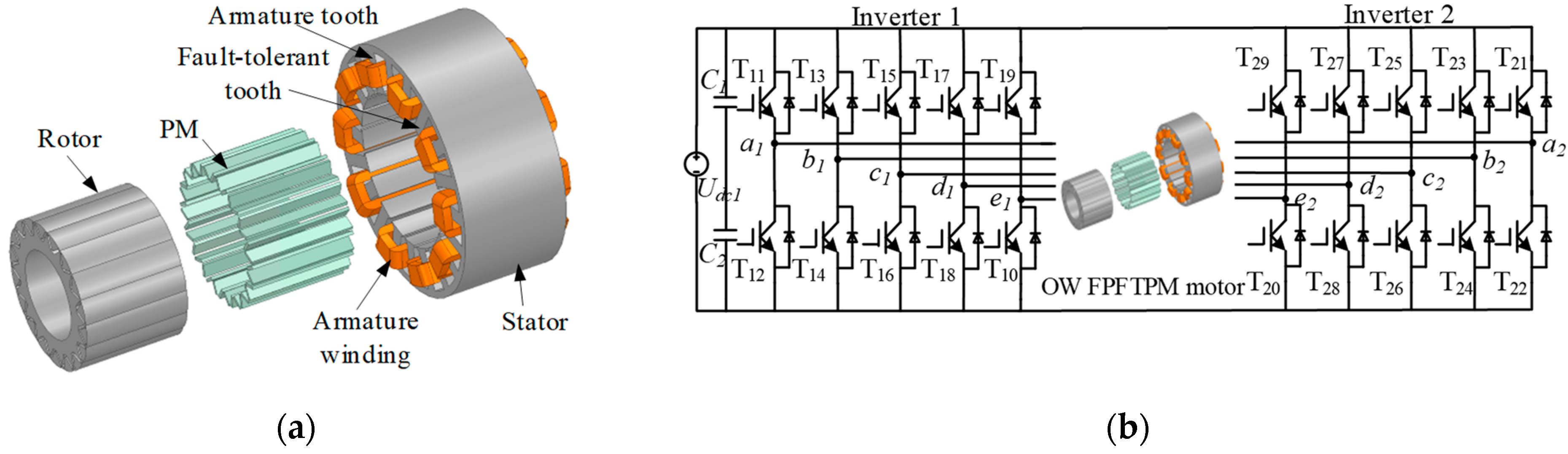
2.1. The Description of OW FPFTPM Motor Drives

The configuration of the FPFTPM motor used in this paper is shown in Figure 1a. The FPFTPM motor is designed as single-layer fractional concentrated winding with the fault-tolerant tooth employed in the stator. Therefore, the stator phase windings have almost no electric, magnetic, and thermal coupling, and the fault-tolerance performance can be greatly improved. The main advantage of the FPFTPM motor is the adoption of the fault-tolerant tooth on the stator, which can also effectively eliminate the influence between faulty phases and other healthy phases. In addition, the self-inductance is almost constant, and the maximum mutual inductance is 0.035 mH (0.259% of the self-inductance). Thus, the mutual inductance and reluctance effects are negligible. The specifications of the FPFTPM motor are listed in Table 2.
The topology of OW FPFTPM motor drives is shown in Figure 1b. It can be seen from Figure 1b that OW FPFTPM motor drives consist of a common DC bus, an inverter 1 and an inverter 2, and an FPFTPM motor. Tij represents the power switches of the drive, i = 1, 2 denotes the power switches belonging to inverters 1 and 2, and j = 1, 2, 3, 4, and 5, which corresponds to the five phases of the FPFTPM motor, respectively. The OW topology can also effectively eliminate the interaction between the faulty phase and other normal phases, and thereby enhance the reliability of the drives.
The two inverters, inverters 1 and 2, are supplied by single DC power Udc, therefore, the eliminating common-mode voltage-vectors modulation strategy is adopted. The switch state of Si = 1 means that the upper power switch of the leg, I, is on and the lower power switch is off. Si = 0 means reversely, where i is a1, b1, c1, d1, e1, a2, b2, c2, d2, and e2. The sequence number of the voltage vectors is the corresponding decimal number of Si, so 10101 denotes the voltage vector of U21, the rest of the voltage vectors and so on. The distribution of the eliminating voltage vectors is shown in Figure 2. When the reference voltage vector uref is in sector I, as shown in Figure 2, uref can be generated by the voltage vectors U16-2, U17-6, U25-7, U27-15, U0-0, and U31-31, where the first number represents the voltage vector generated by inverter 1 and the second number denotes the voltage vector generated by inverter 2.
The space-harmonic magnetomotive force is the direct cause of torque ripple. With the increased number of the phases, the order of the space-harmonic magnetomotive force generated by the fundamental current of the five-phase motor increases. However, the amplitude decreases, which optimizes the torque ripple and improves the efficiency of motor operation. In addition, due to the redundancy of the phase number, when one or two phases of the five-phase motor or the corresponding inverter leg fails, appropriate fault-tolerant control strategies can be adopted to achieve continuous operation of the five-phase motor without restarting or stopping. Therefore, the five-phase motor has strong fault tolerance and high reliability.

2.2. Open-Switch Fault Analysis of OW FPFPTM Motor Drives

It can be seen from section II that each phase winding of FPFTPM motor adopted an independent H-bridge for the power supply. When analyzing the open-switch fault, each phase can be discussed as a separate unit. Take phase A as an example, according to the faulty switches number within phase A, it can be divided into four groups: a single faulty switch, two faulty switches, three faulty switches, and four faulty switches.

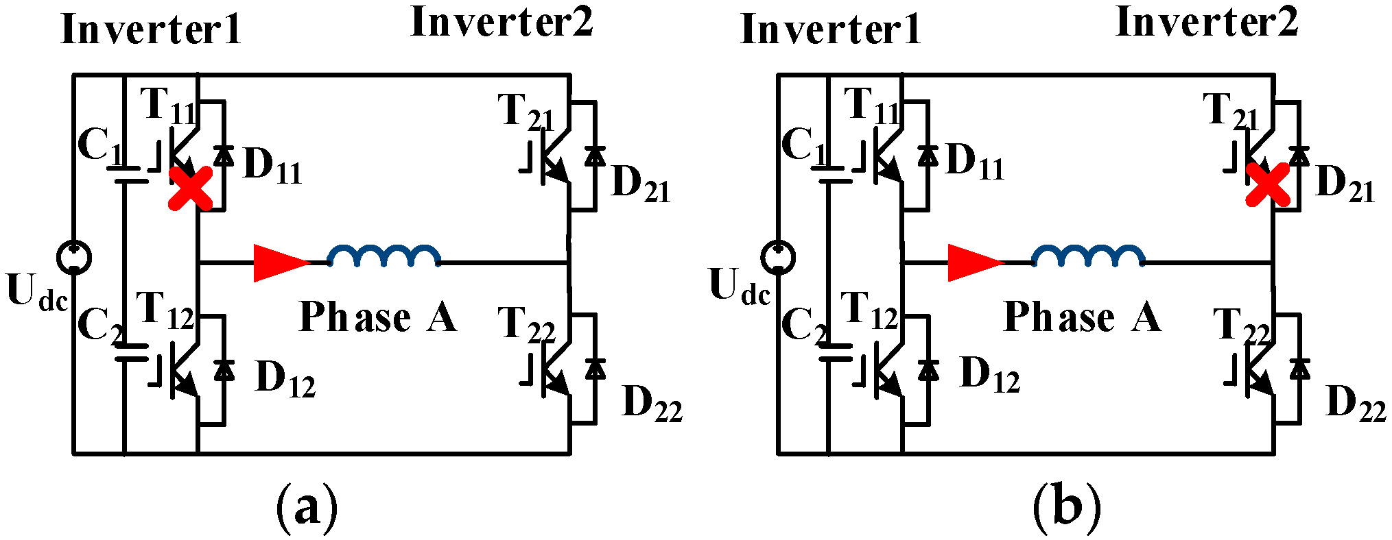
2.2.1. Open-Circuit Fault in the Single Switch

According to Figure 3a, the current following the direction of the arrow is defined as positive. When single open-switch fault occurs in T11, the DC bus fails to provide the positive voltage to the winding and there is only a negative half-cycle current in phase A. Similarly, when single open-switch fault occurs in T21 as shown in Figure 3b, the DC bus also fails to provide a negative voltage to the winding, and only a positive half-cycle current exists in phase A. According to symmetry, when T12 has an open-switch fault, the behavior of the phase current is the same as T21. Additionally, when T22 has an open-switch fault, the behavior of the phase current is the same as T11.

2.2.2. Open-Circuit Faults in Two Switches

When two switches have an open-circuit fault in phase A, there are six possible situations in accordance with the location of the open-switch fault. If the two faulty switches are not diagonally opposite, which includes the open-circuit fault in T11, T21 or T11, and T12, then the DC bus voltage cannot provide energy for phase A. Consequently, there is no current in phase A. Similarly, the same occurs for the situations when there is an open-circuit fault in T12, T22 or T21, and T22. However, when the open-circuit fault occurs at diagonally opposite T11 and T22, as shown in Figure 4a, the DC bus can also provide negative voltage to the windings through T21 and T12, resulting in a negative half-cycle current in phase A. Likewise, when there are open-circuit faults in T21 and T12, as displayed in Figure 4b, the DC bus can still provide positive voltage to the windings through T11 and T22, so there is a positive half-cycle current in phase A.

2.2.3. Open-Circuit Faults in Three and Four Switches

When any three switches of the H-bridge power cell within phase A have open-circuit faults, there is no current existing in phase A. Similarly, when all four switches have open-circuit faults, the phase A current is also zero.
Based on the above analysis, when the faulty power switch is diagonally opposite the H-bridge power cell, the OW FPFTPM motor drives will show the same behavior and one kind of faulty phase current type corresponds to multiple situations of open-switch faults. Therefore, the open-switch fault cannot be merely decided by the faulty phase current type.

3. Detection Method for the Open-Switch Fault

The open-switch fault detection of OW FPFTPM motor drives is divided into two levels, one is to identify the faulty phase and the other is to distinguish the faulty switch within the H-bridge power cell. The content of this paper focuses on the open-switch fault within one phase. The two levels are introduced separately below.

3.1. Determination of the Faulty Phase

Because the motor drives adopt high-performance closed-loop control, the feedback stator current can track the reference current in real time in normal operation. The five-phase current of the FPFTPM motor can be expressed as:
i n ( t ) = I m sin ω t n 1 2 π 5
where n = 1 through to 5, corresponds to either A, B, C, D, or E five-phase, respectively, and the phase current does not contain a third harmonics current during normal operation. When an open-switch fault occurs, the residual of each phase current can be defined as
f n t = i n r e f t i n m t
where inref represents the reference current and inm represents the measured feedback current. fn = (f1, f2, f3, f4, f5) corresponds to the residual current of each phase. During the normal operation, the residual could be guaranteed to be zero. When there is open-switch fault, the feedback current of the faulty phase becomes zero, or exists in the positive or negative half-cycle. When the faulty phase current exists in the negative half-cycle, the residual current is presented as:
f n t = I m sin ω t n 1 2 π 5 n 1 2 π 5   ω t   n 1 2 π 5 + π 0 π + n 1 2 π 5   ω t   n 1 2 π 5 + 2 π
When the faulty phase current exists in the positive half-cycle, the residual current is presented as:
f n t = 0 n 1 2 π 5   ω t   n 1 2 π 5 + π I m sin ω t n 1 2 π 5 π + n 1 2 π 5   ω t   n 1 2 π 5 + 2 π
The residual current fn is transformed to the fundamental α-β plane and the third harmonic α3-β3 plane as:
f α - β = T α β [ f n ] T = i α β r e f i α β m f α 3 - β 3 = T α 3 β 3 [ i n r e f i n m ] T = i α 3 β 3 r e f i α 3 β 3 m f 0 = i 0 r e f i 0 m T α - β = 2 5 1 cos α cos 2 α cos 3 α cos 4 α 0 sin α sin 2 α sin 3 α sin 4 α T α 3 - β 3 = 2 5 1 cos 3 α cos 6 α cos 9 α cos 12 α 0 sin 3 α sin 6 α sin 9 α sin 12 α
where α = 0.4π, fα-β, and fα3-β3 are the residual currents that belong to orthogonal subspaces, the α-β plane and the α3-β3 plane, and iαβref and iαβm are the reference current and the measured current, respectively, in the α-β plane. Likewise, iα3β3ref and iα3β3m are the reference current and the measured current, respectively, in the α3-β3 plane. Moreover, i0ref and i0m are the reference zero-sequence current and the measured zero-sequence current, respectively. Since the back EMF of FPFTPM motors does not contain the third harmonic, the current component should be controlled only by existing in the α-β plane during normal operation. When an open-circuit fault occurs, the feedback current cannot dynamically follow the reference current and the phase current has a third harmonic component in the α3-β3 plane. As a result, the residual current appears in the third harmonic plane. The detection method proposed in this paper is based on the third harmonic residual current. In order to enhance the accuracy of the detection algorithm, a standardized vector, fα3β3N(t), is defined and illustrated as follows:
f α 3 N t = 1 i s r e f 1 i s m i α 3 m f β 3 N t = 1 i s r e f 1 i s m i β 3 m
where i s r e f and i s m represent the amplitude of the reference current and the feedback current in the stationary reference frame, respectively. Their expression is as follows:
i s r e f = i α m 2 + i β m 2 + i α 3 r e f 2 + i β 3 r e f 2 + i 0 r e f 2     i s m = i α m 2 + i β m 2 + i α 3 m 2 + i β 3 m 2 + i 0 m 2
To eliminate the influence of the fundamental current component, the reference current component in (7) is replaced by the measured current, and the residual current in stationary reference frame is introduced into the equation to obtain:
i s r e f = i α r e f f α 2 + i α r e f f α 2 + i α 3 r e f 2 + i β 3 r e f 2 + i 0 r e f 2 i s m = i α r e f f α 2 + i α r e f f α 2 + i α 3 r e f f α 3 2 + i β 3 r e f f β 3 2 + i 0 r e f i 0 m 2
Substitute (8) into (6) to get:
f α 3 N t = 1 K 1 ( 1 + i α 3 r e f 2 + i β 3 r e f 2 + i 0 r e f 2 K 2 ) 1 ( 1 + ( i α 3 r e f f α 3 ) 2 + ( i β 3 r e f f β 3 ) 2 + ( i 0 r e f i 0 m ) 2 K 2 ) × ( i α 3 r e f f α 3 ) f β 3 N t = 1 K 1 ( 1 + i α 3 r e f 2 + i β 3 r e f 2 + i 0 r e f 2 K 2 ) 1 ( 1 + ( i α 3 r e f f α 3 ) 2 + ( i β 3 r e f f β 3 ) 2 + ( i 0 r e f i 0 m ) 2 K 2 ) × ( i β 3 r e f f α 3 ) K = ( i α r e f f α ) 2 + ( i α r e f f α ) 2
It can be concluded from (9) that fα3N and fβ3N are zero when the OW FPFTPM motor drives are in normal operation. Conversely, when an open-switch fault occurs, fα3N and fβ3N are no longer zero due to the appearance of the third harmonic current. According to (9), the trajectory of fα3N and fβ3N under an open-switch fault in phase B are presented in Figure 5. It can be concluded that the locus of (fα3N fβ3N) shows different features depending on the faulty phase current type. Therefore, the slope of the trajectory can be used to distinguish the faulty phase. When the open-switch fault occurred in the rest of the phases, the whole locus of (fα3N fβ3N) is shown in Figure 6. In the figure, the symbols ‘+’ and ‘−’ represent the faulty phase current existing in the positive half-cycle and the negative half-cycle, respectively.
According to the analysis of the (fα3N fβ3N), the identification of the faulty phase can be divided into two steps. Specifically, firstly checking whether there is an open-switch fault followed by the detection of the faulty phase. To determine the occurrence of the open-switch fault, the average amplitude Fi(t) is defined as follows:
F i t = 1 T t t T t t f α 3 N 2 + f β 3 N 2 1 / 2 d t
where T(t) = 2π/ω, and the dynamic window [tT(t); T(t)] is used to prevent false alarms and enhance the anti-interference performance of the detection algorithm. If the fault feature Fi(t) is close to zero, the drives are in healthy states. However, if Fi(t) exceeds the threshold of Fth, the drives have an open-switch fault. Therefore, the open-switch fault of the drives can be detected by Fi(t).
The next step is to identify the faulty phase. As mentioned earlier, it can be achieved through the trajectory slope of (fα3N fβ3N). To accelerate the convergence speed and improve the identification of the faulty phase, the least squares fitting method based on the forgetting factor is used for parameter identification. The specific formula is shown as follows:
K k = P k 1 H k T H k P k 1 H k T + λ R k 1 x k = x k 1 + K k y k H k x k 1 P k = λ 1 I K k H k P k 1
where k is the number of beats, Hk is the input data, corresponding to fα3N, and yk is the output data, corresponding to fβ3N. Pk is the covariance, Kk is the gain coefficient, and x ^ k is the parameter to be identified. In particular, the choice of the forgetting factor, λ, is significant due to its influence on the convergence speed and tracking ability of the algorithm. In this study, λ is set to be 0.98, which not only ensures the rapid convergence of x ^ k , but also prevents oscillation and reduces the tracking error. After x ^ k is identified, the angle of the trajectory slope is deduced as follows:
F P H = arctan x k   i f   x k 0 π + arctan x k i f   x k < 0 =   n 1 π 5 ± π 18
To enhance the anti-interference performance of the algorithm, π/18 is selected as the safety margin, as displayed in Figure 6. Through (12), the faulty phase can be identified. As the faulty current type is related to the open-switch fault, in order to identify the faulty phase current type, the average value of the faulty vector is defined as follows:
F α 3 N = 1 T t t T t T t f α 3 N d t F β 3 N = 1 T t t T t T t f β 3 N d t
The faulty phase current type can be determined based on the average value of the residual vector Fα3N and Fβ3N. In the different faulty phases, the faulty phase current type can be identified as shown in Table 3.
The flow chart of faulty phase detection is shown as Figure 7.

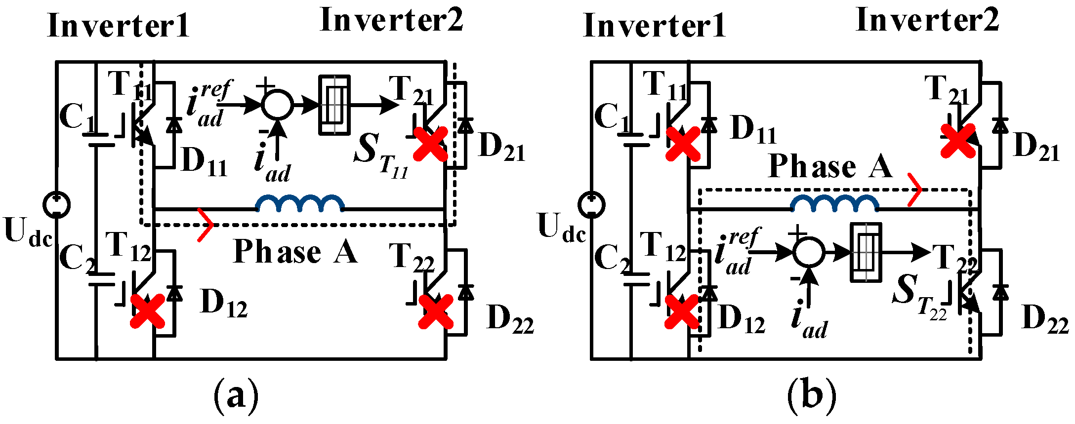
3.2. Identification of the Faulty Switch within the H-Bridge Power Cell

In section A, after the identification of the faulty phase, the faulty phase current type can also be determined. However, one faulty phase current type is corresponding to several situations of open-switch fault within one H-bridge power cell. Therefore, in this section, an online current injection test method is proposed to accurately identify the open-circuit switches within one H-bridge power cell.
Given the distinctiveness of the H-bridge power cell, all four of the switches have an independent current flow path. When there is an open-switch fault in OW FPFTPM motor drives, the back EMF still exists in the faulty phase winding. It is noted that the back EMF can be used as the power supply for all four switches within the H-bridge power cell.
As the back EMF is an AC voltage signal, the four switches within the H-bridge will usually have a half-cycle to withstand the forward voltage of the back EMF. During this period, the switch can be controlled to turn on and the current will appear in the winding. Consequently, the reference-injection current can be set to be 180° phase shift with the back EMF, and the specific expression is as follows:
i n   d r e f = a sin θ n 1 2 π 5  
where n = 1, 2, 3, 4, and 5 representing phase A, B, C, D, and E, respectively, and ‘a’ represents the reference current amplitude of the faulty phase. Through the hysteresis current feedback control of the faulty phase, the switching sequence of the corresponding switch is obtained.
Take the phase A winding as an example, if phase A winding has a negative half-cycle current type, it can be deduced that the switches T21 and T12 must be healthy, and that at least one faulty switch exists in T11 and T22. Therefore, it is necessary to conduct a current injection test on T11 and T22 to accurately identify the faulty switches.
During the first test of T11, the remaining three switches are turned off through removing the gate signals of the three switches as shown in Figure 8a. The reference current of phase A is set according to (14), and the gate signals of T11 are obtained through the hysteresis controller. If T11 is healthy, the test current in phase A will follow the reference current. Otherwise, when T11 has an open-switch fault, the test current is always zero. The root mean square (RMS) and average (AVG) of the test current in phase A are used to determine whether T11 is faulty. If T11 is healthy, T22 must be faulty, and the test ends. If T11 has an open-switch fault, it is necessary to check T22, and perform the second current injection test as revealed in Figure 8b. The test process of T22 is similar to T11. The remaining three switches are actively disconnected except T22, and the gate signals of T22 can also be obtained through the hysteresis controller. If T22 is healthy, the test current will follow the reference one. If T22 has an open-switch fault, the test current is always zero. So far, the accurate identification of the faulty switch can be completed through two current injection tests.
Likewise, if the faulty phase has the positive half-wave current as shown in Figure 9a,b, it can be inferred that T11 and T22 are in heathy states, and either T12 or T21 has an open -switch fault. In order to accurately identify the faulty switch, the current injection tests for T12 and T21 are similar to those for T11 and T22. Accordingly, the RMS and AVG of the test current can be utilized to identify whether T11 is faulty.
Next, when there is no current in the faulty phase A, there are nine possible open-switch fault situations. The current injection test method is shown in Figure 10. When the first current injection detection is performed, the gate signals of T12 and T22 are actively removed, and only T11 and T21 are left in the H-bridge power cell, as depicted in Figure 10a. When T11 withstands a forward voltage, T21 must withstand a reverse voltage. Conversely, when T21 bears a forward voltage, T11 must bear a reverse voltage. Therefore, the test current flow paths of the two switches are independent of each other in their respective half-current cycles. When T11 is turned on, a positive half-cycle test current will appear in phase A. When T21 is turned on, a negative half-cycle test current will appear in phase A. The gate signals of T11 and T21 can be obtained by the hysteresis controller. After the first current injection test, if the test current appears in phase A within one current cycle, then it can be determined that both T12 and T22 must have open-circuit faults, and the detection process ends. If the test current is a positive half-cycle current with amplitude ‘a’, it can be judged that T11 is healthy, T21 and T22 have open-switch faults, and only the state of T12 is unknown. Therefore, T12 needs to be tested separately, and the test process is the same as described in Figure 9b. If the test current is a negative half-cycle current, it can be judged that T21 is healthy, T11 and T12 have open-switch faults, and only the state of T22 is unknown. Therefore, T22 needs to be tested separately, and the test process is the same as described in Figure 8b. If there is no current in phase A during the current detection process, it indicates that both T11 and T21 have open-switch faults. The next step is to detect the states of T12 and T22. The detection diagram is presented in Figure 10b. the figure shows that the gate signals of T12 and T22 can be obtained by the hysteresis controller. In all cases above, the RMS and AVG of the test current are used to determine whether the T12 and T22 are faulty, and the fault detection of all the switches is completed. The identification of the faulty switch within the H-bridge power cell is as shown in Figure 11.
The reference test current is artificially set, having no correlation with the speed and load. Therefore, the influence of the speed and load on the test current can be eliminated, thereby reducing the false alarm. Additionally, when the open-switch fault occurs in other phases, the faulty switch identification procedure is similar to that for phase A.

4. Experimental Results and Discussion

4.1. Experimental Test Bench

To verify the effectiveness of the open-switch fault detection method proposed in this paper, an experimental test bench was built based on the DSP28377D processor as shown in Figure 12. The magnetic powder brake provides the required load to the drives, which is connected to the OW FPFTPM motor through the torque sensor. In addition, the power switches employed in inverter 1 and inverter 2 are insulated gate bipolar transistors (IGBT) with the switching sequence of 10 kHz. The speed during the experimental verification is 600 r/min and the torque is 4N∙m. The threshold, Fth, of the diagnostic variables Fi, Fα3N, and Fβ3N is set to be 5 × 10⁻³. The angle error threshold, Fe, is set to be 10°, and the RMS and AVG threshold, Ith, of the test current is set to be 0.07. Additionally, the reference current amplitude ‘a’ during the current injection test is selected as 0.5 A.

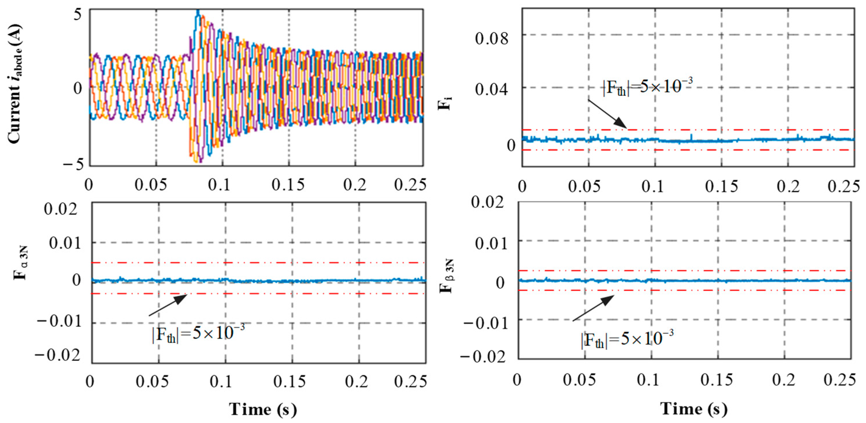
4.2. Results and Discussion

Figure 13a presents the dynamic process from the normal operation to the occurrence of an open-switch fault in T11 of phase A and then to the current injection test. When T11 has an open-switch fault at t = 0.04 s, the faulty phase current only exists in the negative half-cycle, showing consistence with the analysis. With the value of the diagnostic variable, Fi, exceeding Fth, it can be judged that the drives have an open-switch fault. Next, the faulty phase A is determined by the faulty phase angle, FPH. To avoid misjudgment, the examination of the faulty phase is delayed for a half-cycle of the current. After the delay is over, FPH is close to zero, and within plus or minus 10°.It is finally determined that the open-switch fault occurs in phase A. Since |Fα3N| > Fth, Fβ3N = 0, it can be inferred from Table 3 that the faulty phase has a negative half-cycle current and the switches T12 and T21 are healthy.
Consequently, either the switch T11 or T22 has an open-switch fault and the current injection test is further required. The current injection test is carried out twice and each test time is one current cycle. Once the half-current cycle delay is over, the current injection test is applied according to Figure 9. When the first test is performed, the gate signals of T22, T21, and T12 are removed, and the gate signal of T11 is obtained through the current controller. The RMS and AVG of the test current are close to zero and it can be determined that T11 has an open-switch fault. When performing the second test, the gate signals of T22, T21, and T12 are removed, and gate signal of T11 is obtained through the current controller. The RMS and AVG of the test current are close to 0.25 and 0.16, respectively. It can be inferred that T22 is healthy and that the entire single open-switch fault detection process has been completed. When the faulty phase has a negative half-cycle current, two current injection tests are also required, and the detection process is shown in Figure 8.
Figure 13b shows the experimental results when the diagonally opposite switches T14 and T23 in phase B have open-switch faults. This shows that the faulty current of phase B exists in the positive half-cycle. After a current cycle, the diagnostic variable Fi detects the occurrence of the open-switch fault, and FPH = 40° determines that the faulty phase is B as revealed in Figure 13b. Compared with Figure 13a, FPH changed significantly. When the open-circuit fault occurs in other phases, FPH is shown as in Figure 6. Then, the average fault vector |Fα3N| > Fth, |Fβ3N| > Fth notes that the faulty phase current type is a positive half-cycle waveform, indicating that T13 and T24 are healthy. According to Figure 9, two current injection tests are required. In the first test, the gate signals of T13, T23, and T24 are removed, and the gate signal of T14 is obtained through the current controller; in the second test, the gate signals of T13, T14, and T24 are removed, and the gate signal of T23 is obtained through the current controller. In both tests, the RMS and AVG of the test current are zero, which means T14 and T23 have open-circuit faults.
Figure 14a demonstrates the experimental results when the three switches T13, T14, and T23 of phase B have open-switch faults. FPH indicates that phase B suffers from open-circuit fault. Furthermore, it is observed that the faulty phase current type is zero. Based on the faulty phase current type, the current injection test is conducted as described in Figure 10. In the first test, the gate signals of T14 and T24 are removed, and gate signal of T13 and T23 are obtained through the current controller; and the first test indicates that T13 and T23 have open-switch faults as the test current is zero. In the second test, the gate signals of T13 and T23 are removed, and gate signal of T14 and T24 are obtained through the current controller, and the second test shows the AVG and RMS of the test current are 0.25 and 0.16, respectively, which means T24 is healthy and T14 is the faulty switch. The experimental results show that the detection method can effectively detect the open-switch fault in the case of three switches.
When all four switches in phase B have open-switch faults, the experimental results are shown in Figure 14b. In this case, from the occurrence of the fault to the current injection test, there is no current in phase B, and the diagnostic variables Fi, Fα3N, Fβ3N, and FPH are similar to those in Figure 14a. Then, based on the AVG and RMS of the test current, it is noted that T13, T23, T14, and T24 of phase B have open-circuit faults.
To further verify the anti-interference performance of the detection method under normal operation proposed in this article, Figure 15 reveals the experimental results when the speed changes from 300 r/min to 600 r/min. It is evident from Figure 15, that both the amplitude and frequency of the current have changed. During transient states, the diagnostic variables Fi, Fα3N, and Fβ3N have been kept within the normal bands. The above experimental results verify that the detection method proposed in this paper has a robust performance during the transient variation of the load and speed.

4.3. Key Findings of the Detection Method

In the present study, an open-switch fault detection method based on open-winding OW FPFTPM motor drives is proposed to solve the problem that the fault at the diagonally opposite position within the H-bridge power cell shares the same fault characteristics. Some key findings of the detection method are presented as follows:
(1)
The back EMF can be used as the power supply. Combined with the characteristics of the OW structure, the current injection test can be used to identify the open-switch fault;
(2)
Compared with the conventional detection method, the proposed method can extract detailed open-switch fault information online within one half-current cycle, including the fault phase, the fault current type, and the fault switch position. Based on the extracted information, the drives can easily realize fault-tolerant control under the open-switch fault;
(3)
The detection method uses the residual of the third harmonic current for fault detection, so it is not affected by the variable of motor load. Furthermore, this method does not require additional sensors and additional circuits, thus reducing the detection cost, which is suitable for engineering applications.

5. Conclusions

This paper proposed an online open-switch fault detection method based on OW FPFTPM motor drives, which can accurately identify the faulty phase and the faulty switches of the H-bridge power cell within one phase. During the fault detection, the residual vector of the third harmonic current and the least square method based on the forgetting factor are used to detect the faulty phase and the faulty current type. In addition, to accurately identify the faulty switches within one phase, a current injection test method is proposed. This method mainly uses the back EMF of the faulty phase winding as excitation and applies a gate signal to the test switches within the H-bridge power cell. The gate signals can be obtained by a hysteresis controller, and the state of each switch within the H-bridge power cell can be accurately identified by the AVG and RMS of the test current in the faulty phase. The proposed detection method does not require additional sensors apart from the current sensors, which are already provided for the current measurements. Furthermore, the experimental results for OW FPFTPM motor drives are presented in order to evaluate the proposed detection method.

Author Contributions

Conceptualization, R.C. and S.Y.; methodology, R.C.; software, R.C.; validation, R.C., S.Y. and S.L.; formal analysis, R.C.; investigation, R.C.; resources, R.C.; data curation, R.C.; writing—original draft preparation, R.C.; writing—review and editing, S.Y. and S.L.; visualization, R.C.; supervision, S.Y. and S.L.; project administration, R.C.; funding acquisition, R.C. and S.Y. All authors have read and agreed to the published version of the manuscript.

Funding

This research was supported in part by the Natural Science Foundation of the Jiangsu Higher Education Institutions of China (grant number 22KJB470026) and the Lv Yang Jin Feng Program of Yangzhou (grant number YZLYJFJH2021YXBS130).

Data Availability Statement

Not applicable.

Conflicts of Interest

The authors declare no conflict of interest.

Notations

inrefThe reference current
inmThe measured feedback current
fnThe residual current of each phase
fα-βThe residual current in the α-β plane
fα33The residual current in the α3-β3 plane
iαβrefThe reference current in the α3-β3 plane
iα3β3mThe measured current in the α3-β3 plane
i0refThe reference zero-sequence current
i0mThe measured zero-sequence current
i s r e f The amplitude of the reference current in the stationary reference frame
i s m The amplitude of the feedback current in the stationary reference frame
fα3NThe fault feature in α3-axis
fβ3NThe fault feature in β3-axis
FiMagnitude of the fault feature in the α3-β3 plane
HkThe input data
ykThe output data
PkThe covariance
KkThe gain coefficient
λThe forgetting factor
FPHThe angle of the faulty phase
Fα3NThe average value of fα3N
Fβ3NThe average value of fβ3N
i n d r e f The reference current amplitude of the faulty phase

References

  1. Kim, H.; Lee, C. Shape parameters design for improving energy efficiency of IPM traction motor for EV. IEEE Trans. Veh. Technol. 2021, 70, 6662–6673. [Google Scholar] [CrossRef]
  2. Razi, M.; Murgovski, N.; McKelvey, T.; Wik, T. Design and comparative analyses of optimal feedback controllers for hybrid electric vehicles. IEEE Trans. Veh. Technol. 2021, 70, 2979–2993. [Google Scholar] [CrossRef]
  3. Jung, S.; Ko, J.J. Study on regenerative energy recovery of electric vehicle through voltage control using switched capacitor. IEEE Trans. Veh. Technol. 2021, 70, 4324–4339. [Google Scholar] [CrossRef]
  4. Shi, Z.; Sun, X.; Cai, Y.; Yang, Z. Robust design optimization of a five-phase PM hub motor for fault-tolerant operation based on taguchi method. IEEE Trans. Energy Convers. 2020, 35, 2036–2044. [Google Scholar] [CrossRef]
  5. Lin, H.; Zhao, F.; Kwon, B. Analysis and control of the permanent magnet synchronous motor with auxiliary modular design. IEEE Trans. Magn. 2018, 54, 8208206. [Google Scholar] [CrossRef]
  6. Zhang, L.; Zhu, X.; Gao, J.; Mao, Y. Design and analysis of new five-phase flux-intensifying fault-tolerant interior-permanent-magnet motor for sensorless operation. IEEE Trans. Ind. Electron. 2020, 67, 6055–6065. [Google Scholar] [CrossRef]
  7. Zhou, H.; Zhou, C.; Tao, W.; Wang, J.; Liu, G. Virtual-stator-flux-based direct torque control of five-phase fault-tolerant permanent-magnet motor with open-circuit fault. IEEE Trans. Power Electron. 2020, 35, 5007–5017. [Google Scholar] [CrossRef]
  8. Priestley, M.; Fletcher, J.; Tan, C. Space-vector PWM technique for five-phase open-end winding PMSM drive operating in the overmodulation region. IEEE Trans. Ind. Electron. 2018, 65, 6816–6827. [Google Scholar] [CrossRef]
  9. Belkhode, S.; Jain, S. Optimized switching PWM technique with common-mode current minimization for five-Phase open-end winding induction motor drives. IEEE Trans. Power Electron. 2019, 34, 8971–8980. [Google Scholar] [CrossRef]
  10. Priestley, M.; Farshadnia, M.; Fletcher, J. FOC transformation for single open-phase faults in the five-phase open-end winding topology. IEEE Trans. Ind. Electron. 2020, 67, 842–851. [Google Scholar] [CrossRef]
  11. Jlassi, I.; Cardoso, A. A single method for multiple IGBT, current, and speed sensor faults diagnosis in regenerative PMSM drives. IEEE J. Emerg. Sel. Top. Power Electron. 2020, 8, 2583–2599. [Google Scholar] [CrossRef]
  12. Mazzoletti, M.; Bossio, G.; Angelo, C.; Espinoza-Trejo, D. A model-based strategy for interturn short-circuit fault diagnosis in PMSM. IEEE Trans. Ind. Electron. 2017, 64, 7218–7228. [Google Scholar] [CrossRef]
  13. Gonz’alez-Prieto, I.; Duran, M.; Rios-Garcia, N.; Barrero, F.; Mart´ın, C. Open-switch fault detection in five-phase induction motor drives using model predictive control. IEEE Trans. Ind. Electron. 2018, 65, 3045–3055. [Google Scholar] [CrossRef]
  14. Khil, S.; Jlassi, I.; Cardoso, A.; Estima, J.; Mrabet-Bellaaj, N. Diagnosis of open-switch and current sensor faults in PMSM drives through stator current analysis. IEEE Trans. Ind. Appl. 2019, 55, 5925–5937. [Google Scholar] [CrossRef]
  15. Shi, T.; He, Y.; Wang, T.; Tong, J.; Li, B.; Deng, F. An improved open-switch fault diagnosis technique of a PWM voltage source rectifier based on current distortion. IEEE Trans. Power Electron. 2019, 34, 12212–12225. [Google Scholar] [CrossRef]
  16. Cheng, Y.; Sun, Y.; Li, X.; Dan, H.; Lin, J.; Su, M. Active common-mode voltage-based open-switch fault diagnosis of inverters in IM-drive systems. IEEE Trans. Ind. Electron. 2021, 68, 103–115. [Google Scholar] [CrossRef]
  17. Hang, J.; Zhang, J.; Cheng, M.; Ding, S. Detection and discrimination of open-phase fault in permanent magnet synchronous motor drive system. IEEE Trans. Power Electron. 2016, 31, 4697–4709. [Google Scholar] [CrossRef]
  18. Lamb, J.; Mirafzal, B. Open-circuit IGBT fault detection and location isolation for cascaded multilevel converters. IEEE Trans. Ind. Electron. 2017, 64, 4846–4856. [Google Scholar] [CrossRef]
  19. Wu, X.; Chen, C.; Chen, T.; Cheng, S.; Mao, Z.; Yu, T.; Li, K. A fast and robust diagnostic method for multiple open-circuit faults of voltage-source inverters through line voltage magnitudes analysis. IEEE Trans. Power Electron. 2020, 35, 5205–5220. [Google Scholar] [CrossRef]
  20. Shahin, A.; Martin, J.; Pierfederici, S. Zero-sequence current based diagnostic method for open-switch fault detection in parallel inverters system. IEEE Trans. Power Electron. 2019, 34, 3750–3764. [Google Scholar] [CrossRef]
  21. Guo, H.; Guo, S.; Xu, J.; Tian, X. Power switch open-circuit fault diagnosis of six-phase fault tolerant permanent magnet synchronous motor system under normal and fault-tolerant operation conditions using the average current park’s vector approach. IEEE Trans. Power Electron. 2021, 36, 2641–2660. [Google Scholar] [CrossRef]
  22. Kong, J.; Wang, K.; Zhang, J.; Zhang, H. Multiple open-switch fault diagnosis for five-phase permanent magnet machine utilizing currents in stationary reference frame. IEEE Trans. Energy Convers. 2021, 36, 314–324. [Google Scholar] [CrossRef]
  23. Salehifar, M.; Arashloo, R.; Equilaz, J.; Sala, V.; Romeral, L. Fault detection and fault tolerant operation of a five phase PM motor drive using adaptive model identification approach. IEEE J. Emerg. Sel. Top. Power Electron 2014, 2, 212–223. [Google Scholar] [CrossRef]
  24. Trabelsi, M.; Semail, E.; Nguyen, N. Experimental investigation of inverter open-circuit fault diagnosis for biharmonic five-phase permanent magnet drive. IEEE J. Emerg. Sel. Top. Power Electron. 2018, 6, 339–351. [Google Scholar] [CrossRef]
  25. Trabelsi, M.; Nguyen, N.; Semail, E. Real-time switches fault diagnosis based on typical operating characteristics of five-phase permanent-magnetic synchronous machines. IEEE Trans. Ind. Electron. 2016, 63, 4683–4694. [Google Scholar] [CrossRef]
  26. Li, Z.; He, Y.; Gao, Y.; Zhang, X.; Wang, B.; Ma, H. A Model-Data-Hybrid-Driven diagnosis method for Open-Switch faults in power converters. IEEE Trans. Power Electron. 2021, 36, 4965–4970. [Google Scholar] [CrossRef]
  27. Abari, I.; Hamouda, M.; Sleiman, M.; Slama, H.; Kanaan, Y.; AI-Haddad, K. Open-Circuit fault detection and isolation method for Five-Level PUC inverter based on the Wavelet Packet Transform of the radiated magnetic field. IEEE Trans. Instrum. Meas. 2022, 71, 3502611. [Google Scholar] [CrossRef]
  28. Yan, H.; Xu, Y.; Cai, F.; Zhang, H.; Zhao, W.; Gerada, C. PWM-VSI fault diagnosis for a PMSM drive based on the fuzzy logic approach. IEEE Trans. Power Electron. 2019, 34, 759–768. [Google Scholar] [CrossRef]
Figure 1. The OW FPFTPM drives: (a) Configuration of the OW FPFTPM motor.; and (b) Topology of OW FPFTPM drives.
Machines 10 00829 g001
Figure 2. Distribution of the voltage vectors. (a) α-β plane (ωs); and (b) α33 plane (ωs).
Machines 10 00829 g002
Figure 3. A Single switch with open-circuit faults: (a) Open-circuit fault inT11; and (b) Open-circuit fault in T21.
Machines 10 00829 g003
Figure 4. Two switches showing an open-circuit fault: (a) Open-circuit fault in T11 and T22; and (b) Open-circuit fault in T12 and T21.
Machines 10 00829 g004
Figure 5. Locus of (fα3N fβ3N) when there is an open-switch fault in phase B: (a) Drives have no open-switch fault; (b) Negative half-cycle current; (c) Positive half-cycle current; and (d) Null current.
Machines 10 00829 g005
Figure 6. Locus of (fα3N fβ3N) according to different faulty phases.
Machines 10 00829 g006
Figure 7. Flow chart of faulty phase detection.
Machines 10 00829 g007
Figure 8. Identification procedure with the negative half-cycle current in phase A: (a) First test; and (b) Second test.
Machines 10 00829 g008
Figure 9. Identification procedure with the positive half-cycle current in phase A: (a) First test; and (b) Second test.
Machines 10 00829 g009
Figure 10. Identification procedure with no current in phase A: (a) First test; and (b) Second test.
Machines 10 00829 g010
Figure 11. Identification of the faulty switch within the H-bridge power cell.
Machines 10 00829 g011
Figure 12. Experimental test bench.
Machines 10 00829 g012
Figure 13. Experimental results: the blue line represents the diagnostic variable, and the red line represents the threshold of amplitude. (a) T11 with an open-circuit fault in phase A; and (b) T14 and T23 with an open-circuit fault in phase B.
Machines 10 00829 g013
Figure 14. Experimental results: the blue line represents the diagnostic variable, and the red line represents the threshold of amplitude. (a) T13, T14, and T23 with an open-circuit fault in phase B; and (b) All the four switches with an open-circuit fault in phase B.
Machines 10 00829 g014
Figure 15. Experimental results during the variable speed dynamic process (the blue line represents the diagnostic variable, and the red line represents the threshold of amplitude).
Machines 10 00829 g015
Table 1. Summary of detection methods.
Detection MethodsFault FeatureShortfalls
voltage-basedcommon-mode voltage
zero-sequence voltage
collector–emitter voltage
require additional detection circuits, sensors, or observers
current-basedfundamental current
low-order harmonic current
zero-sequence current
vulnerable to load, focus on the star-connected inverter
intelligent algorithmneural network
wavelet analysis
fuzzy logic
require a large amount of training data, high computational complexity, focus on the star-connected inverter
Table 2. Specifications of the FPFTPM Motor.
ParameterValueParameterValue
Rated-phase voltage100 Vd-axis inductance Ld13.7 mH
Rated current4.7 Aq-axis inductance Lq15.9 mH
Stator resistance0.5 ΩRated speed1500 r/min
Pole pair9DC bus voltage250 V
Table 3. Identification of The Faulty Phase Current Type.
Faulty PhaseFα3NFβ3NFaulty Phase Current Type
Fα3N = 0Fβ3N = 0Null current
AFα3N < 0Fβ3N = 0Negative half-cycle current
Fα3N > 0Fβ3N = 0Positive half-cycle current
Fα3N=0Fβ3N = 0Null current
BFα3N > 0Fβ3N > 0Negative half-cycle current
Fα3N < 0Fβ3N < 0Positive half-cycle current
Fα3N = 0Fβ3N = 0Null current
CFα3N < 0Fβ3N < 0Negative half-cycle current
Fα3N > 0Fβ3N > 0Positive half-cycle current
Fα3N = 0Fβ3N = 0Null current
DFα3N < 0Fβ3N > 0Negative half-cycle current
Fα3N > 0Fβ3N < 0Positive half-cycle current
Fα3N = 0Fβ3N = 0Null current
EFα3N < 0Fβ3N > 0Negative half-cycle current
Fα3N > 0Fβ3N < 0Positive half-cycle current
Publisher’s Note: MDPI stays neutral with regard to jurisdictional claims in published maps and institutional affiliations.

