1. Introduction
The large headframe is the core structure of a mine hoisting system, and also a high-rise and hollow steel-framed building [
1,
2,
3]. With the development of mine hoisting system towards large-scale, higher requirements are put on the structural design of the large headframe [
4,
5]. In the process of traditional design, the designers combined practical experience to enlarge small-sized headframes, according to the required proportions. Then, based on the working load, the strength of the enlarged headframe was checked by the static analysis method [
6,
7]. The traditional design method cannot calculate the dynamic characteristics of a large headframe, but also cannot analyze the dynamic response of a large headframe under the coupling action of the vibration loads of various components of the hoisting system, such as the head sheave, the motor, and the wire rope. As a result, resonance, structural damage, deflection, and settlement may occur in the later application of the large headframe [
8,
9,
10,
11,
12]. Therefore, dynamic characteristic analysis is of great significance for the structural optimization design of a large headframe.
Dynamic characteristic analysis has become a popular direction in the research of large headframes [
13,
14,
15,
16]. For the study of dynamic characteristic analysis, the experimental measurement method or the simulation calculation method can be used. Hua Jian conducted modal experiments on the large headframe of a deep well drilling rig with resonance problems, and obtained the eigenfrequencies that caused the resonance of the headframe. By adding mass to the local structure, to change the eigenfrequencies of the large headframe, the generation of the resonance phenomenon was resolved [
17]. An experimental test is an effective way to obtain the dynamic characteristic parameters of a large headframe. However, the high cost of experimental measurement and the limitation of field conditions limit its application. Therefore, based on the similarity principle, Meiqiu Li established a reduced size model for the heavy and large headframe of an oil drilling rig, and verified the design rationality of the large headframe model through dynamic experiments [
18]. Making a simplified model to carry out experiments can reduce the cost of experimental measurement. However, the experimental results are sometimes unsatisfactory, and the model usually needs to be modified repeatedly.
In the Chinese national standard GB50385-2018, Design Standards for Large Headframes in Mines, simulation methods should be used for dynamic analysis of large headframe structures in mines [
19]. With the development of finite element technology, as a dynamic analysis method, the finite element method has been widely used in the fields of mechanics and architecture [
20,
21,
22,
23,
24,
25,
26,
27]. Some scholars have used the finite element method to analyze the dynamic characteristics of large headframes. Liu Yue established a finite element model of a large headframe for a coal mine, and obtained the eigenfrequencies of the large headframe through simulation calculation. After that, the load frequency causing resonance of the large headframe was obtained through a vibration measurement experiment, and an improved method for structural optimization design was proposed [
28]. Yin Qixiang established a finite element model of a large headframe, and calculated the stress of the large headframe through simulation [
29]. Feng Guan conducted experiments on the large headframe of a drilling platform. Then, the bearing capacity of the large headframe was analyzed, and a reinforcement scheme was proposed [
30]. Generally, the first and second eigenfrequencies of a large headframe are very closely spaced, and this could be an issue for the actual system identification from experimental recordings, especially in situ and under ambient vibrations. Fortunately, an identification algorithm was proposed to deal specifically with closely-spaced eigenfrequencies, which is completely independent of the user experience, fully objective, and based on statistical principles and a machine learning clustering approach [
31].
It was confirmed in the previous research of our team that a dynamic analysis and structural optimization can be quickly and effectively carried out using the finite element method [
20,
28]. For one thing, the eigenfrequencies and vibration mode of the structure can be calculated through modal analysis, which can judge whether the structure has similar eigenfrequencies and adverse vibration modes. For another, the steady-state vibration response of the structure under a periodic alternating load varying according to sinusoidal law can be calculated through harmonic response analysis, which can judge whether the structure can withstand resonance and other adverse effects caused by forced vibration. Therefore, a finite element model of a large headframe in Laizhou gold mine will be established in this paper. Then, the dynamic characteristic analysis of the headframe will be carried out. Finally, combined with the analysis results, a novel method for dynamic characteristic analysis and structural optimization design of a large headframe is proposed.
2. Finite Element Model
The large headframe in Laizhou gold mine is studied in this paper, and the overall structure of the large headframe is introduced first. The large headframe was designed based on the traditional idea (static method). At the beginning of the design, several local structures were strengthened, but dynamic analysis is urgently needed to verify whether there are problems with the existing design. The headframe is composed of 95 box-beams and two H-beams, and the beams are connected by welding. The overall dimension of the headframe is 46.5 m (length) × 36 m (width) × 85.963 m (height). According to the existing headframe design, a finite element model was established. First, the SolidWorks software was used to establish a three-dimensional (3D) model of the large headframe, as shown in
Figure 1a. Then, the 3D model was imported into ANSYS software, to generate the finite element model. After that, according to the design and application data of the large headframe, the material parameters, connection relationships, and fixed constraints were set in the finite element model. The fixed constraints of the large headframe are shown in
Figure 1b. The main material parameters of the Q345 steel used in the large headframes are shown in
Table 1. After setting the material parameters, the finite element model of large headframe could be obtained, and the overall structural quality is about 1.465 × 10
6 kg. Finally, the finite element model of the large headframe was meshed. In order to ensure the calculation accuracy and efficiency, the TET10 element and the HEX20 element were used to mesh the finite element model. The TET10 elements were used for meshing the box-beams, while the HEX20 elements were used for meshing the H-beams. There are a large number of irregular reinforcement plates inside the box-beams, so the box-beams were hard mesh using the HEX20 elements. Therefore, the box-beams were quickly and effectively meshed using the TET10 elements. Meanwhile, the H-beams are relatively regular and could be quickly meshed using the HEX20 elements. The meshed model contains 17111656 elements and 34537529 nodes, and the average element quality is 0.61. Due to the large number of mesh elements and nodes, a server platform with 80 cores of CPU and 512 GB of physical memory was used for parallel computing.
3. Modal Analysis
Based on the finite element model obtained in
Section 2, a modal analysis is carried out in this section. A modal analysis, the free vibration analysis, is a method to study the dynamic characteristics of structures. The free vibration analysis assuming negligible small damping is shown in Equation (1).
where M is the mass matrix,
is the acceleration column vector, K is the stiffness matrix, and
x is the displacement column vector.
The ultimate goal of modal analysis is to calculate the eigenfrequencies and vibration mode of a structure. For a linear system, the acceleration and displacement of free vibration satisfy the following equations:
where
is the eigenvector of the
i-th vibration mode,
is the
i-th eigenfrequencies, and
t is the time. Moreover, the cosine form of Equations (2) and (3) can also be written in sine form. Substituting Equations (2) and (3) into Equation (1), the following equation can be obtained:
Through Equation (4), the eigenvectors of the i-th eigenfrequencies and the i-th vibration mode can be obtained. Theoretically, the structure has countless eigenfrequencies and vibration modes, i → ∞. However, usually only the first few eigenfrequencies and vibration modes have a large influence on the overall structural vibration.
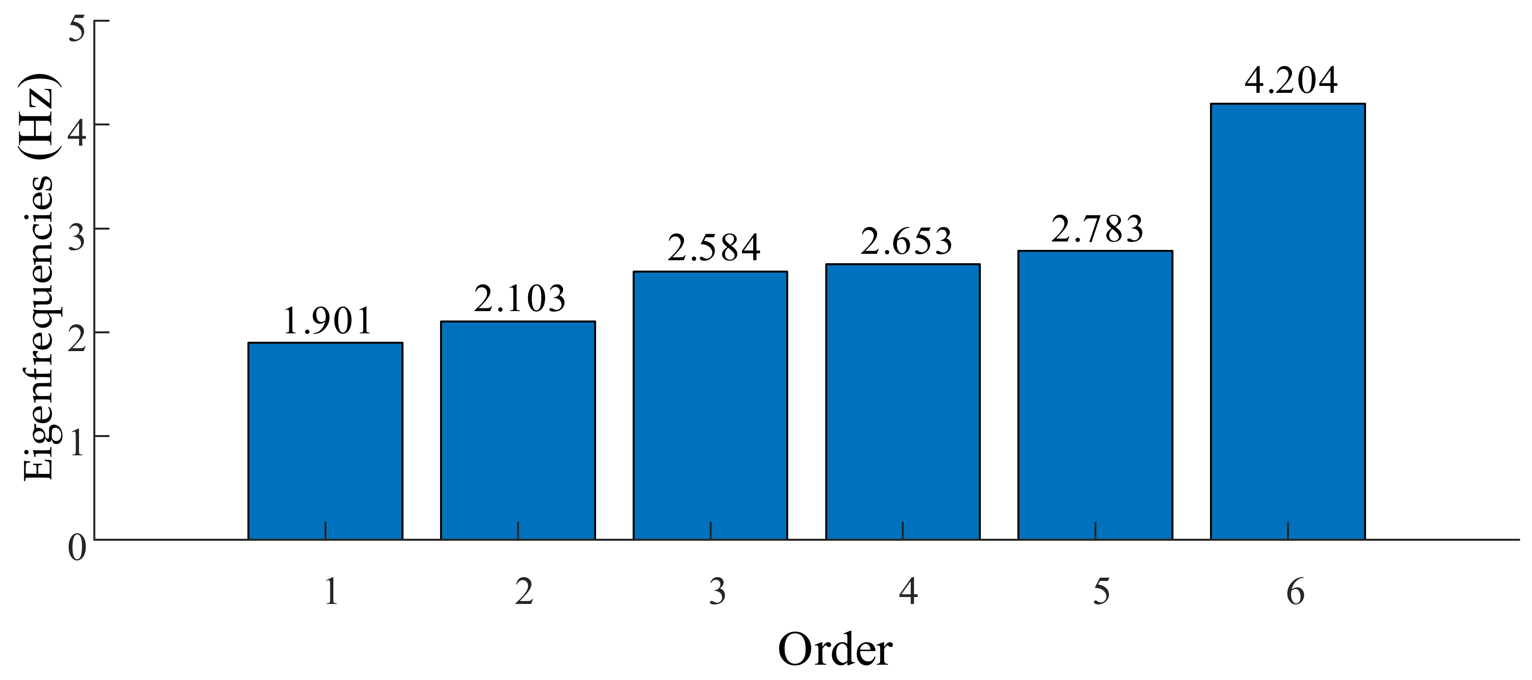
For the large headframe, the first six-order eigenfrequencies and vibration modes were calculated and analyzed using AYSYS software in this paper. The eigenfrequencies are shown in
Figure 2, and the vibration modes are shown in
Figure 3.
In
Figure 3, the overall structural vibration modes are displayed. The black wireframes are the initial structure. The overall structure amplitudes were amplified 200,000 times, to enable clear observation of the primary vibration modes, and the amplitudes are indicated by different colors. The maximum amplitude is indicated by the red color, while the minimum amplitude is indicated by the blue color. In addition, the positions of the maximum amplitude and minimum amplitude are marked, and three translational motions and three rotational motions of the overall structure vibration modes are marked. Combined with
Figure 2 and
Figure 3, it can be concluded that the large headframe has the following inherent characteristics:
- (1)
The eigenfrequencies of the first six-order are relatively small and are mainly affected by the overall mass and stiffness of the structure of the large headframe.
- (2)
The first-order and second-order eigenfrequencies are relatively close, and the difference between them is 0.202 Hz.
- (3)
The eigenfrequencies of the second-order and third-order are quite different, and the difference between the two is 0.481 Hz;
- (4)
The eigenfrequencies of the third-order and fourth-order are very close, and the difference between them is only 0.069 Hz.
- (5)
The eigenfrequencies of the fourth-order and fifth-order are relatively close, and the difference between them is 0.130 Hz.
- (6)
The eigenfrequencies of the fifth-order and the sixth-order are quite different, and the difference between them is 1.421 Hz.
- (7)
The first six vibration modes are dominated by the overall vibration of the large headframe, and the main vibration modes of each mode are significantly different, including three translational motions along the x, y, and z axes and three rotational motions around the x, y, and z axes.
- (8)
The maximum amplitudes of the second-order, third-order, fourth-order, and sixth-order vibration modes are located in the top area of the large headframe. The reason for this is that the stiffness of the top of the large headframe is less than that of other areas of the large headframe. The maximum amplitude of the first-order and fifth-order vibration modes is located in the lower area of the large headframe. The reason for this is that the stiffness of the lower area of the large headframe along the x direction is relatively small.
- (9)
The minimum amplitude of the first six-order vibration modes are all located at the bottom of the large headframe model. The reason for this is that the fixed constraint is set at the bottom of the large headframe model, and its amplitude is 0.
Through a modal analysis of the large headframe in Laizhou gold mine, the eigenfrequencies and vibration modes of the headframe were obtained. The analysis results showed that the first six-order eigenfrequencies of the large headframe are small, and the values of the multi-order eigenfrequencies are relatively close. The first six-order vibration modes are dominated by the overall vibration of the large headframe, including three translational motions and three rotational motions. Since the multi-order eigenfrequencies values are relatively close, when the large headframe is subjected to alternating loads of similar frequencies, the large headframe will easily produce a strong vibration response, that is, resonance.
The alternating load on the large headframe mainly comes from the vibration generated by the key components of the hoisting system. During the working process, the hoisting system is a typical multi-source coupled vibration system. In addition to the general vibration of rotating equipment, such as motors, friction wheels, and head sheaves, the coaxiality errors caused by manufacturing and installation can cause axial vibrations in rotating equipment. The axial vibration will cause lateral vibration of the wire rope, which in turn will affect the axial vibration of the rotating equipment. The skip moves along the tank track under the traction of the wire rope. Due to the force of the guide rail of the tank track, the skip will vibrate and oscillate in multiple directions, and these vibrations will in turn affect the tension and vibration of the wire rope. Eventually, the alternating loads generated by the motor, friction wheel, head sheave, wire rope, and skip are coupled together at the head sheave, and act together on the large headframe, causing the vibration response of the large headframe.
In order to explore the vibration response characteristics of the large headframe under alternating loads, the harmonic response analysis of the large headframe will be carried out in the next section. The modal analysis in this section lays the foundation for the subsequent harmonic response analysis.
4. Harmonic Response Analysis
A periodic cyclic response of a structure will be caused by a periodic alternating load, including the transient response and the steady-state response. Harmonic response analysis is a dynamic analysis method to calculate the steady-state response of structures under periodic alternating loads that vary according to a sinusoidal law. Based on the modal analysis in
Section 3, a harmonic response analysis will be carried out in this section. The harmonic response analysis only calculates the steady-state forced vibration response of the structure, without considering the transient vibration at the beginning of excitation. Through harmonic response analysis, it is possible to determine whether the structure can withstand resonance, fatigue, and other adverse effects caused by forced vibration. The rotating machinery of the mine hoisting system is large, such as the head sheave with a sliding bearing 5.5 m in diameter, and the head sheave rotates at a low frequency (only several Hz) even at the maximum speed. Therefore, the mechanical vibration of alternating loads below 5 Hz, which could impact the large headframe, are studied in this paper.
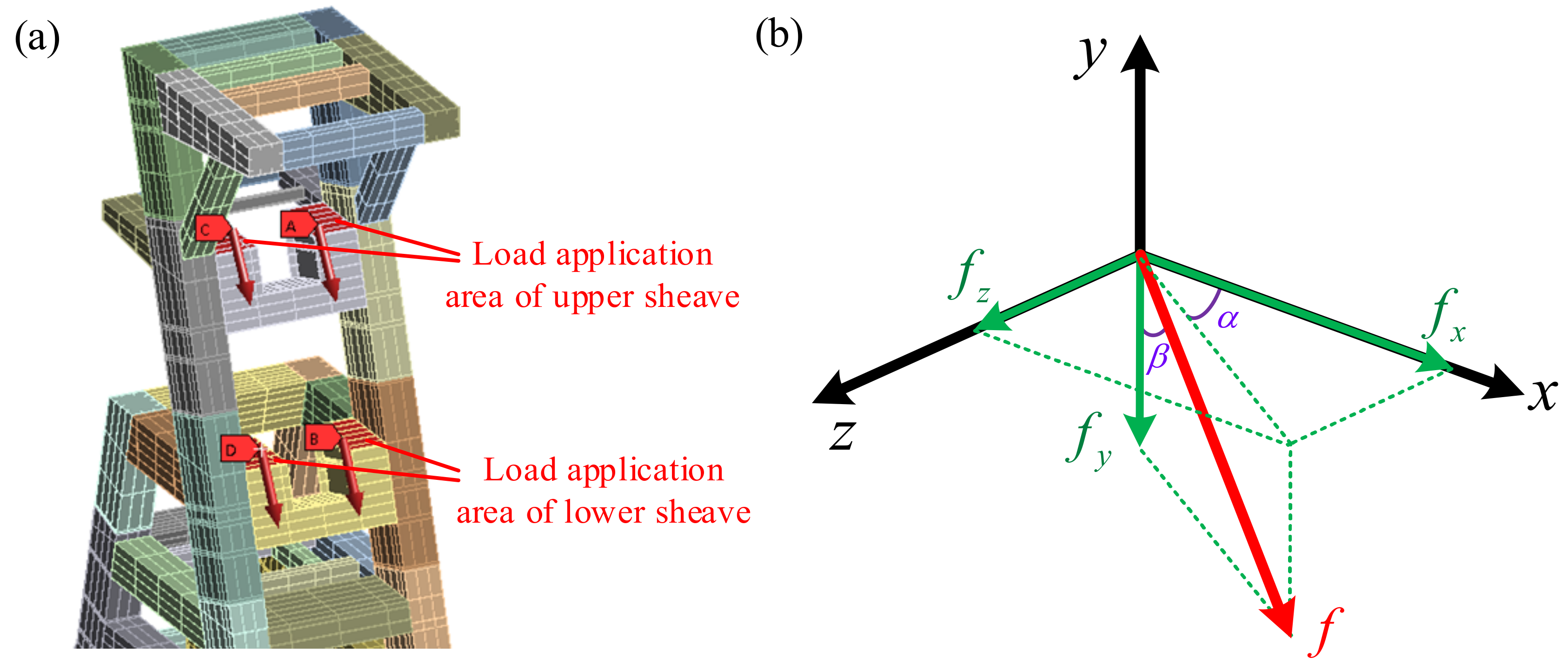
For the large headframe, the harmonic response was calculated and analyzed using AYSYS software. In the finite element model, the material parameters, connection relations, and fixed constraints were set. Then, the model was meshed. The alternating load of the hoisting system will eventually be applied to the large headframe through the head sheave. Therefore, the alternating load
was loaded on the support beams of the upper and lower head sheaves as the alternating load application method, as shown in
Figure 4.
The alternating load
f can be decomposed into the following three components in the
x,
y, and
z directions.
- ①
At the upper head sheave,
,
and
, then
- ②
At the lower head sheave,
,
and
, then
Six kinds of alternating loads were selected for calculation and comparative analysis. The values of the alternating loads can be found in
Table 2.
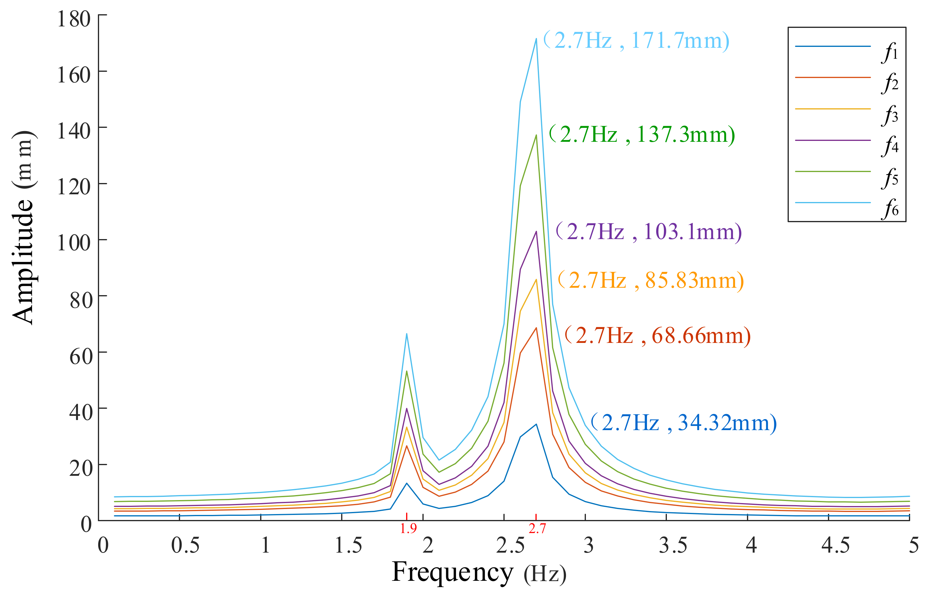
In this paper, the modal superposition method was used to calculate the harmonic response, and the damping coefficient of the system was set as 0.02. The vibration response of the large headframe structure under the alternating load of 0.1–5 Hz frequency was obtained, as shown in
Figure 5. During the analysis, the frequency interval of the alternating load was 0.1 Hz. That is, the alternating load frequencies were 0.1 Hz, 0.2 Hz, 0.3 Hz, …, 4.8 Hz, 4.9 Hz, and 5.0 Hz, respectively.
It can be seen from
Figure 5 that, under different alternating loads, the amplitude of the large headframe has a specific distribution law. Therefore, the vibration response characteristics of large headframes under 0.1–5 Hz frequency alternating loads can be summarized as follows:
- (1)
When the frequency of the alternating load is very small (), the magnitude of the alternating load changes slowly. This is equivalent to applying the alternating load to the large headframe in the form of static load. At this time, the dynamic response of the large headframe is small, and the amplitude is almost the same as the static displacement.
- (2)
When the alternating load frequency is much greater than the eigenfrequencies of the large headframe (), the amplitude of the large headframe is small and the system remains stable.
- (3)
When the alternating load frequency
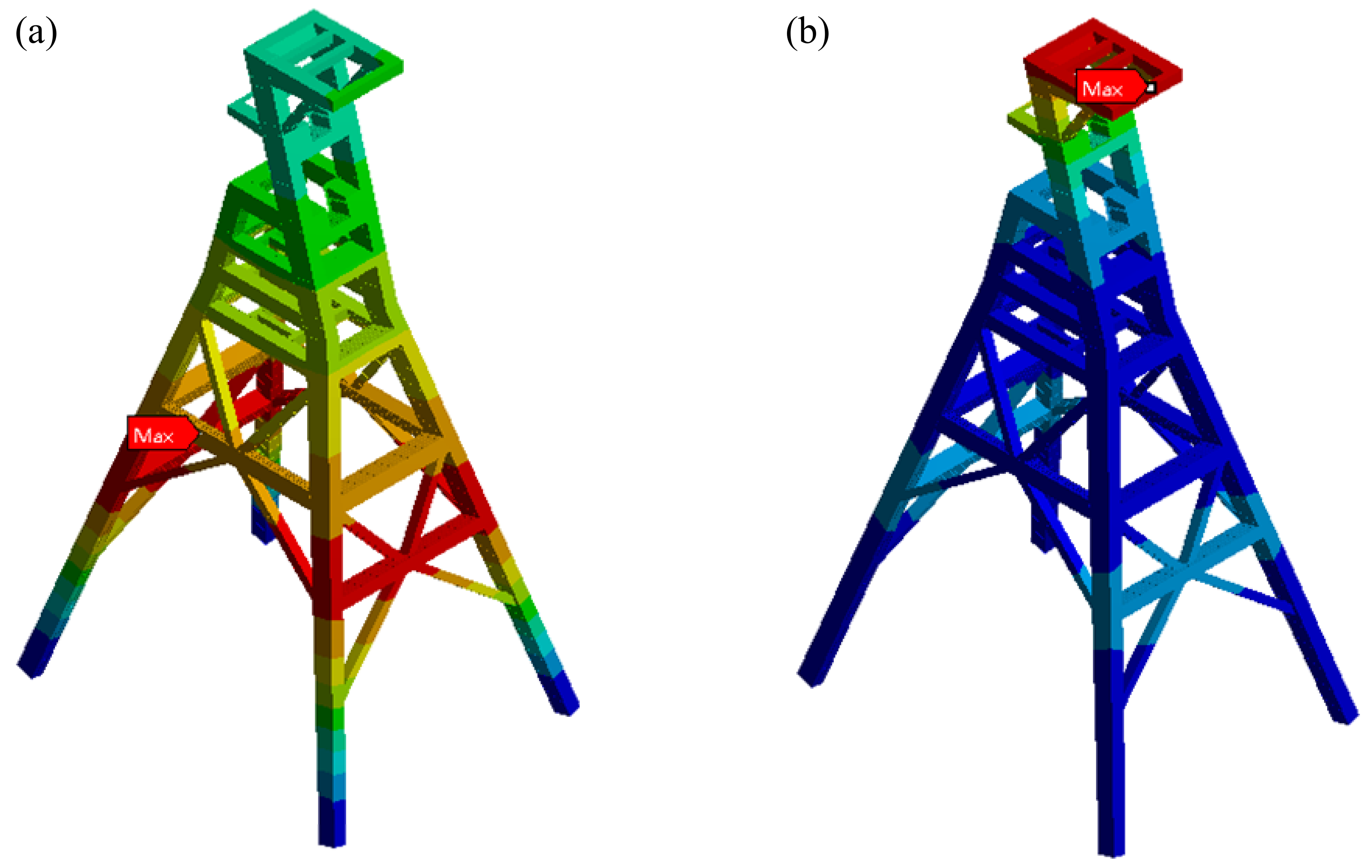
ω = 1.9 Hz, it is close to the first-order eigenfrequencies (1.901 Hz) of the large headframe. At this time, the amplitude of the large headframe increases. However, due to the existence of a damping force, the amplitude is a limited value. The overall vibration mode of the large headframe is similar to the first-order vibration mode of the large headframe. The maximum amplitude is located in the lower region of the inclined legs of the large headframe, as shown in
Figure 6a.
- (4)
When the alternating load frequency
ω = 2.7 Hz, it is close to the fourth-order eigenfrequencies (2.653 Hz) and the fifth-order eigenfrequencies (2.783 Hz) of the large headframe. At this time, the amplitude of the large headframe increases significantly. However, due to the existence of a damping force, the amplitude is a limited value. The overall vibration mode of the large headframe is formed by the superposition of the fourth-order and fifth-order vibration modes of the large headframe. The maximum amplitude is located at the top region of the large headframe, as shown in
Figure 6b.
- (5)
When the alternating load frequency is close to the second-order, third-order, and sixth-order eigenfrequencies (2.103 Hz, 2.584 Hz, and 4.204 Hz) of the large headframe, the amplitude of the large headframe is small and no resonance occurs. The reason for this is that the component of the alternating load in the z direction is small, and it fails to excite the second-order, third-order, and sixth-order vibration modes of the large headframe. Therefore, resonance of the large headframe cannot be caused.
- (6)
Under the same alternating load frequency, the greater the amplitude of the alternating load, the greater the amplitude of the large headframe and the more severe the resonance. When the large headframe resonates, there is a danger of structural damage caused by excessive vibration.
Figure 6.
The overall vibration modes of the large headframe. (a) The mode under an alternating load of 1.9 Hz. (b) The mode under an alternating load of 2.7 Hz.
Figure 6.
The overall vibration modes of the large headframe. (a) The mode under an alternating load of 1.9 Hz. (b) The mode under an alternating load of 2.7 Hz.
Through the harmonic response analysis of the large headframe in Laizhou gold mine, the vibration amplitude under different alternating loads was obtained. The analysis results showed that when the alternating load frequency is close to the first-order eigenfrequencies of the large headframe, the amplitude of the large headframe increases, but it is still within an acceptable range. The fourth- and fifth-order eigenfrequencies of the headframe are very similar. When the large headframe is subjected to alternating loads of similar frequencies, its fourth-order and fifth-order vibration modes are simultaneously excited, and the large headframe will produce a strong vibration response; that is, a strong resonance. At this time, adverse effects, such as structural damage to the headframe, may be caused.
Based on the above analysis, the large headframe designed based on the traditional method may have resonance problems in its later application. Therefore, it is urgent to carry out the structural design optimization of the large headframe, to avoid resonance and adverse effects under alternating loads. The harmonic response analysis in this section determines the vibration response characteristics of the large headframe when resonance occurs, which provides a basis for the improvement of the large headframe structure.
5. Structural Optimization Design
The optimization design of the large headframe structure is carried out in this section. Based on the analysis results in
Section 3 and
Section 4, it is necessary to change the distribution law of the first six-order eigenfrequencies, to solve the problem of two or more eigenfrequencies with very similar values. According to Equation (4), the eigenfrequencies are related to the mass and stiffness of the structure. For structural design optimization, by changing the mass and stiffness of the large headframe, its eigenfrequencies can be changed. Nine different structural optimization schemes for the large headframe are proposed in this section, and the optimal scheme is eventually selected through a comparative analysis.
5.1. Structural Optimization Schemes
According to the vibration mode of the large headframe in
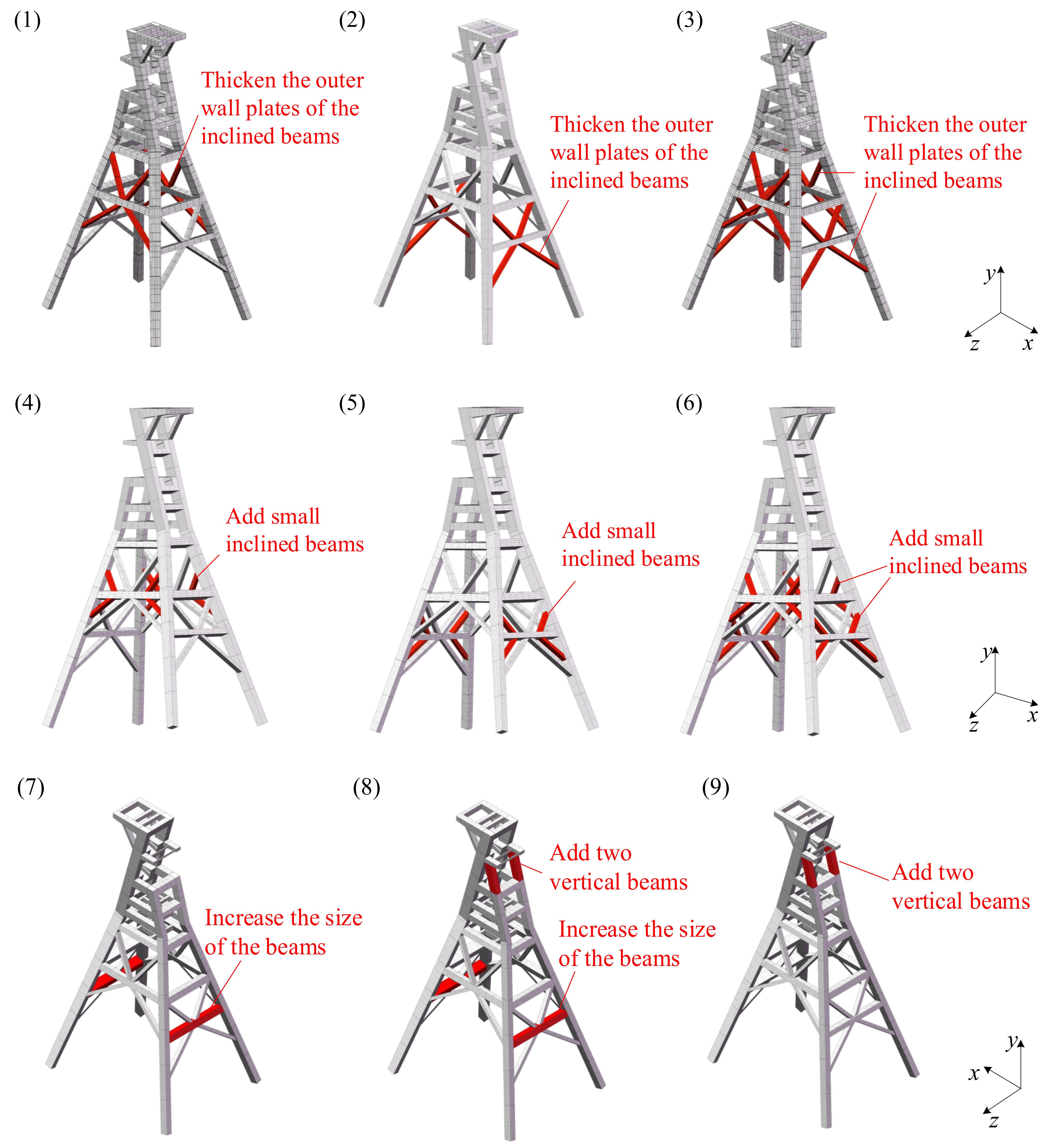
Figure 6, the maximum amplitude is located in the lower region and the top region. Therefore, nine different structural optimization schemes for the lower region and the top region are proposed, as shown in
Figure 7. The nine schemes are as follows:
- (1)
For the lower region of the large headframe, thicken the outer wall plates of the inclined beams along the z direction.
- (2)
For the lower region of the large headframe, thicken the outer wall plates of the inclined beams along the x direction.
- (3)
For the lower region of the large headframe, thicken the outer wall plates of the inclined beams along the z and x directions.
- (4)
For the lower region of the large headframe, add small inclined beams along the z direction.
- (5)
For the lower region of the large headframe, add small inclined beams along the x direction.
- (6)
For the lower region of the large headframe, add small inclined beams along the z and x direction.
- (7)
For the lower region of the large headframe, increase the cross-section size of the beams along the x direction.
- (8)
For the top and lower regions of the large headframe, increase the cross-section size of the cross beams along the x direction. At the same time, add two vertical beams whose cross-sectional size is the same as that of the inclined-leg vertical beam.
- (9)
For the top region of the large headframe, add two vertical beams with the same cross-sectional dimensions as the inclined-leg vertical beams
Figure 7.
The nine different structural optimization schemes of the large headframe (the coordinate system only shows the direction, and the actual origin of the coordinate is located at the mass center of the finite element model).
Figure 7.
The nine different structural optimization schemes of the large headframe (the coordinate system only shows the direction, and the actual origin of the coordinate is located at the mass center of the finite element model).
5.2. Comparison Analysis
The structural optimization of a large headframe changes its mass and stiffness, which in turn causes its eigenfrequencies to change. In order to reduce the adverse effects of resonance, the eigenfrequency changes of the improved large headframe should meet the following conditions: The first six-order eigenfrequencies of the large headframe must be significantly different to prevent the generation of new and very similar eigenfrequencies. In order to select the optimal scheme, the modal analysis results and harmonic response analysis results of the improved large headframe were compared and analyzed.
(1) Modal analysis
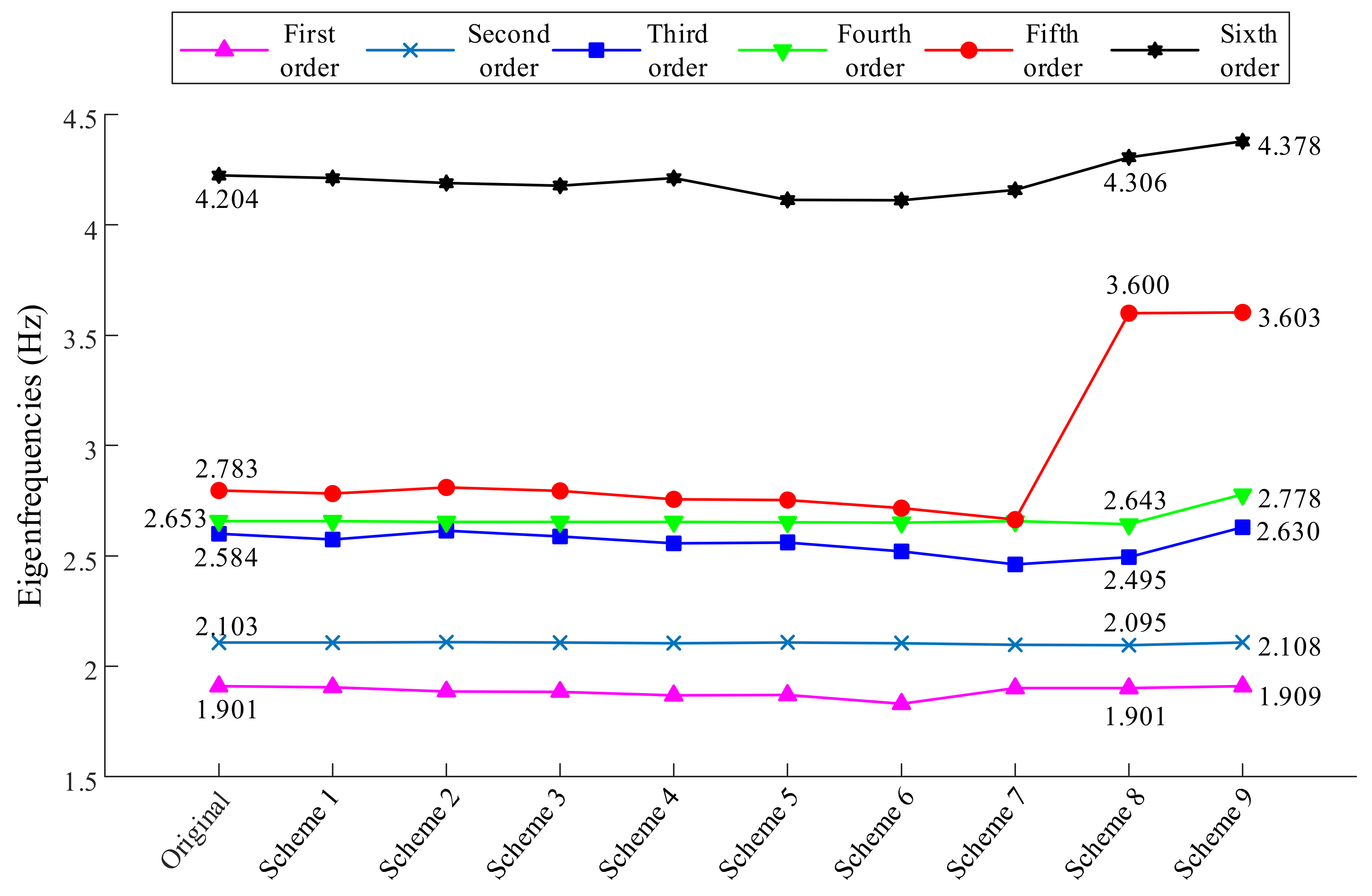
The ANSYS software was used for modal analysis, to calculate the eigenfrequencies of the large headframe. The first six-order eigenfrequencies of the original headframe and the improved headframe under the nine different structural optimization schemes are shown in
Figure 8.
It can be seen from
Figure 8 that the first six-order eigenfrequencies of the large headframe changed after the different schemes were adopted. In schemes 1–7, improvements were made in the lower region of the large headframe, but the change in eigenfrequencies was small. In contrast, in schemes 8 and 9, improvements were made in the top region of the large headframe. The distribution law of the first six-order eigenfrequencies changed significantly, especially the difference between the eigenfrequencies of the fourth-order and the fifth-order increased significantly.
(2) Harmonic response analysis
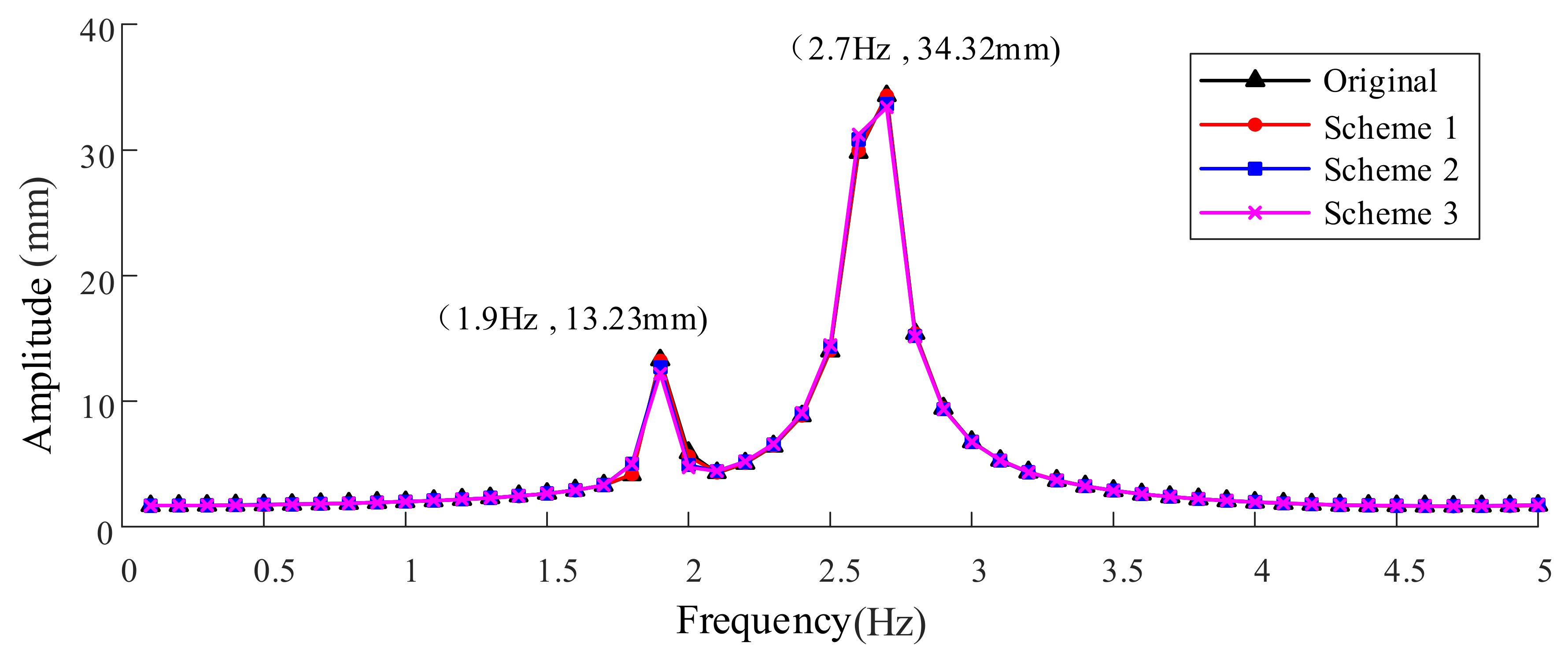
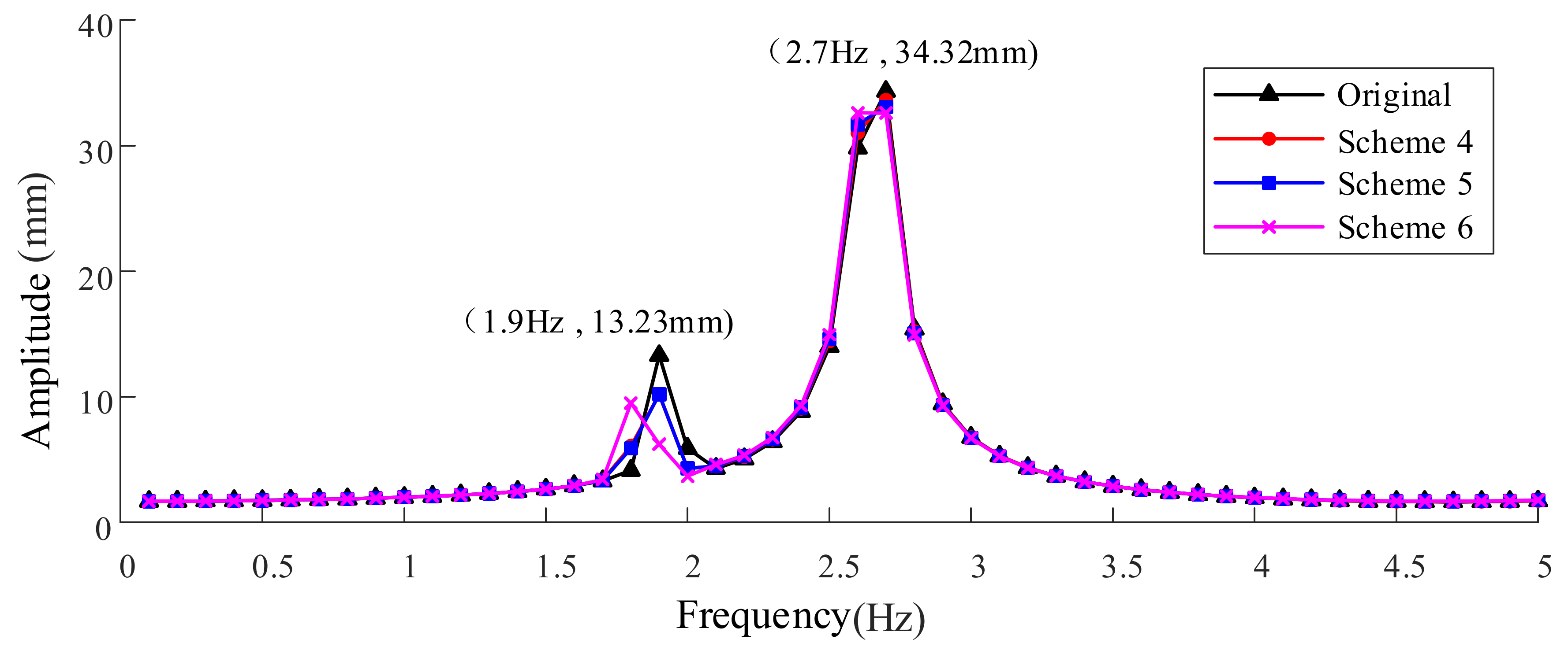
The ANSYS software was used for harmonic response analysis, to calculate the vibration response of the large headframe. The vibration response results of the original headframe and the improved headframe under the nine different structural optimization schemes are shown in
Figure 9,
Figure 10 and
Figure 11, respectively.
It can be seen from
Figure 9,
Figure 10 and
Figure 11, in schemes 1 to 7, the amplitude change of the large headframe was small. In contrast, in schemes 8 and 9, the resonance frequency of the large headframe changed to 3.6 Hz. Meanwhile, the vibration amplitude reduced by 22%, and the maximum amplitude was still at the top region of the large headframe.
When a 2.7 Hz alternating load was applied to the original large headframe, the fourth-order eigenfrequencies (2.653 Hz) and the fifth-order eigenfrequencies (2.783 Hz) of the original large headframe were relatively close. At this time, the fourth-order and fifth-order vibration modes of the large headframe are excited, and their amplitudes are superimposed on each other, which eventually leads to a significant increase in amplitude. For the improved large headframes under scheme 8 and scheme 9, the fourth-order and the fifth-order eigenfrequencies were significantly different. Therefore, when the 3.6Hz alternating load was applied to the modified large headframe, only the fifth-order vibration mode was excited, which led to a decrease in the resonance amplitude compared to the original large headframe.
To sum up, schemes 1–7 were all aimed at the structural improvement of the lower region of the large headframe. Unfortunately, the eigenfrequencies and the vibration amplitude of the large headframe were not changed significantly. Comparatively, in scheme 8, the structures of the lower region and the top region of the large headframe were improved. The eigenfrequencies and vibration amplitude of the large headframe changed significantly, and the resonance amplitude decreased. In scheme 9, the structure of the top region of the large headframe improved. Excitingly, the eigenfrequencies and vibration amplitudes of the large headframes changed significantly, and the resonance amplitudes decreased. Based on the above results, it can be seen that the improvement effects of scheme 8 and scheme 9 were better than the other schemes. Considering the manufacturing and construction cost of a large headframe, the structural form of a large headframe should be as simple as possible, and the added weight should be small. Therefore, among the various structural optimization schemes, the optimal scheme was eventually determined as scheme 9.
Nine different structural optimization schemes for the large headframe were proposed in this section. The eigenfrequencies and vibration amplitudes of the large headframe were obtained through modal analysis and harmonic response analysis, respectively. Through comparative analysis, the optimal scheme was eventually determined as scheme 9.
6. Conclusions
In this paper, the finite element method was used for dynamic analysis of the large headframe in the Laizhou gold mine. Through modal analysis and harmonic response analysis, the eigenfrequencies, vibration mode, and vibration amplitude of the large headframe were obtained. Then, nine different structural optimization schemes for the large headframe improvement were proposed. The main conclusions are summarized, as follows:
The modal analysis results showed that the first six-order eigenfrequencies of the large headframe are small, and the values of the multi-order eigenfrequencies are relatively close. The first six-order vibration modes are dominated by the overall vibration of the large headframe, including three translational motions and three rotational motions. Since the multi-order eigenfrequencies values are relatively close, when the large headframe is subjected to alternating loads of similar frequencies, the large headframe will be prone to the resonance phenomenon. The alternating loads on the large headframe mainly come from the vibration generated by the key components of the hoisting system. The modal analysis laid the foundation for the subsequent harmonic response analysis.
The results of the harmonic response analysis showed that, when the alternating load frequency is close to the first-order eigenfrequencies of the large headframe, the vibration amplitude increases, but it is still within an acceptable range. Therefore, it is urgent to carry out structural design optimization, to avoid resonance and adverse effects. The harmonic response analysis determined the vibration response characteristics of the large headframe when resonance occurs, which provided a basis for the improvement of the large headframe structure.
Based on the results of the modal analysis and harmonic response analysis, it was determined that the structure of the large headframe needs to be improved, and the eigenfrequencies of the improved large headframe needed to avoid a similar resonance frequency range. Then, nine different structural optimization schemes for the large headframe were proposed. The eigenfrequencies and vibration amplitudes of the large headframes were obtained by modal analysis and harmonic response analysis, respectively. Through comparative analysis, the optimal scheme was eventually determined as scheme 9.
In the traditional design process of a large headframe, the designers only consider the effect of a static working load and neglect the effect of mechanical vibrational forcing. As a result, a resonance phenomenon may occur in the application of the large headframe. In order to restrain the resonance phenomenon, a novel method for dynamic characteristic analysis and structural optimization design of a large headframe is proposed in this paper. The proposed method is a complement to the traditional design process of a large headframe. On the one hand, for a new large headframe design, the advantage of using this method is that the interaction of the large headframe dynamic characteristics and the mechanical vibration can be obtained. Meanwhile, the structural optimization and simulation calculation can be carried out during the design process, so as to make an optimal scheme without resonance phenomenon. On the other hand, the analysis results based on the proposed method can provide a basis for the structural modification of large headframes that have resonance phenomenon in practice. In addition, the method and conclusions in this paper can be extended to the analysis of resonance problems for other large structures. However, due to the studied large headframe construction having not been completed, vibration measurement experiments will be conducted in a future work.
