Article

Depth Control of an Oil Bladder Type Deep-Sea AUV Based on Fuzzy Adaptive Linear Active Disturbance Rejection Control

National Center for International Research of Subsea Engineering Technology and Equipment, Dalian Maritime University, Dalian 116026, China
*
Author to whom correspondence should be addressed.
Machines 2022, 10(3), 163; https://doi.org/10.3390/machines10030163
Submission received: 7 January 2022 / Revised: 20 February 2022 / Accepted: 21 February 2022 / Published: 22 February 2022
(This article belongs to the Special Issue Advanced Control of Industrial Electro-Hydraulic Systems)

Abstract

:
The deep-sea autonomous underwater vehicle (AUV) is equipment of vital importance for ocean exploration, monitoring, and surveying. With a variable buoyancy system (VBS), AUV can achieve rising, diving, and hovering in the water column. This paper proposes a deep-sea AUV with an oil bladder type hydraulic VBS, which controls the oil flow rate with a proportional valve. However, the implementation of accurate depth control for AUV faces various challenges due to the varying water density with depth, the non-linear feature of the hydraulic system, and the disturbance from sea flows and currents. To tackle these problems, a third-order linear active disturbance rejection controller (LADRC) and its fuzzy adaptive version were designed and implemented in MATLAB/Simulink based on the state-space function of the proposed AUV system. Compared with the conventional PID controller, the simulation results indicate that the proposed LADRC controller shows strong robustness to disturbance, with other advantages including smaller steady-state error, overshoot, settling time, and response time. Moreover, the proposed fuzzy LADRC controller could further decrease the overshoot caused by the increasing target distance. The results prove that the designed depth controllers can meet the control requirements of the proposed deep-sea AUV.

1. Introduction

The ocean contains abundant resources and is of much research value [1]. With the continuous exploration of the ocean, humans have made many discoveries leading to significant achievements [2,3]. However, the dangers such as high water pressure, darkness, and fluctuations in ocean currents have considerably constrained deep-sea exploration. Humans alone can only be maintained in a limited area and depth. For these reasons, the dangerous task of a deep-diving operation has been drawn towards unmanned systems, such as remotely operated vehicles and autonomous underwater vehicles (AUVs) [4,5]. AUV is a vessel that can travel underwater for surveys, monitoring, and image capturing without the need for operator driving [6]. It was developed into many different forms for completing various missions, e.g., an autonomous buoy used to detect ocean earthquakes and an underwater glider for large-scale investigation [7,8]. However, the key issue for long-term working is saving energy. One way to reduce energy consumption is to use a variable buoyancy system (VBS), which can achieve low energy floating and long-term hovering of AUV in the water column.
VBS is an essential module for underwater vehicles. At present, there are three main types to change buoyancy: mass discarding, ballast water, and oil bladder [9]. Mass discarding VBS is the most straightforward way to obtain extra buoyancy. The vehicle can float rapidly upward or downward by discarding objects like counterweights or ballast systems. Benefiting from the reliability and high efficiency, this kind of system is more commonly used for human-occupied vehicles (HOVs) such as for safeguarding. For example, submersibles such as Nautile [10,11], Alvin [12], and Shinkai6500 [13,14] are all equipped with this system. Compared with mass discarding VBS, ballast water VBS can repeatedly change buoyancy. It has a fixed drainage volume and changes the vehicle’s total mass by pumping seawater into a ballast tank or draining water out of it. Thus, the vehicle buoyancy is further controlled by the water level in the tank.
To overcome external water pressure [15], the ballast water VBS requires a complex valve system and a high-pressure seawater pump [16], which results in structural complexity. It is commonly used as the main VBS for most HOVs, like Shenhai Yongshi [17] and JIAOLONG [18]. However, the ballast water VBSs equipped in AUVs are almost all the on-off type that cannot regulate the flow rate of ballast water and thus limit the vehicles’ hovering performance in a complex underwater environment [19]. In order to achieve accurate buoyancy control, the oil bladder type with repeatable two-way buoyancy regulation is commonly employed. Differing from the ballast water VBS, the oil bladder VBS is a closed system whose total mass is unchanged. It adjusts the drainage volume of the vehicle by pumping oil in or out of an external flexible bladder. By installing the hydraulic system into a closed pressure tolerant shell with an external bladder, the oil bladder VBS has the advantages of being compact, energy-saving, and non-polluting. Based on these advantages, it is often used for accurate depth controlling and as a long deployment vehicle [20]. For example, an oil bladder VBS for the long cruising range AUV with 1000 m rated depth and 18 kg buoyancy capacity was presented in ref. [21].
Moreover, many underwater gliders use one or two oil bladders to change the gliding attitude [22,23,24]. In [25], a buoyancy engine with a swash-plate type axial piston pump for underwater gliders was developed. When drawing oil at high water pressure, the pumping system can work passively, and a damping resistor regulates the motor speed. In [26], a hybrid oil bladder VBS with a passive accumulator was developed for deep-sea gliders, which can effectively utilize the ocean pressure differential energy to realize buoyancy compensation. The main characteristics and differences of the three types of VBS are compared in Table 1. Besides, a new VBS type based on the phase change of paraffin with the advantages of silence and miniaturization appears, but it is still under study [27,28]. Due to the advantages of oil bladder VBS, this paper proposes a deep-sea AUV using an oil bladder VBS with an electro-hydraulic proportional valve to achieve high depth control performance.
AUVs need to change working depth frequently to meet the requirements of different missions. Such as the floating ocean seismograph in [29] needs to have long-term working at deep-sea level and occasionally to float upward to send data. For energy-saving, using VBS to control depth is more appropriate than using thrusters, even if it is of lower efficiency. The main principle of liquid pumping VBS (water ballast and oil bladder) to adjust buoyancy is by changing the effective volume of liquid. To achieve accurate depth control, a variable flow rate VBS with a variable pump or flow control valve is better than an on-off type VBS; meanwhile, an efficient controller is also necessary to be designed. At present, the common basic control methods mainly include proportional integral and derivative (PID) control [30], linear quadratic regulator (LQR), and sliding mode control (SMC) [31]. PID is the most common and easiest to realize control method in engineering because of its simple structure and no requirement for a system model [32]. In [33], the authors use a PID controller to realize the depth control of an AUV by the cooperative working of thrusters and VBSs. In [34], a cascade controller, with a PD upper layer and an on-off type lower layer, is presented for on-off type ballast water VBS. The simulation results demonstrated that the controller has equal display as a variable flow rate VBS. Compared with PID control, LQR using full state feedback can arrive at higher control performance. For example, an underwater glider controlled by it can glide along a spiral trajectory as in [35].
However, the full states of AUV are a challenge to measure; thus, an observer is usually required [36]. Furthermore, fuzzy strategies are often added to a controller to enhance the transient response [37,38]. In [39], the authors compare the performances of PID, SMC, and their fuzzy versions for the depth control of AUV. The simulation results demonstrated that the SMC controller performed better than the PID one, and the fuzzy versions were better than the normal ones. An SMC controller, with excellent anti-ability to disturbances, is widely used in the motion control of underwater vehicles. Some novel works related to SMC theory, such as the dynamic SMC method, the robust sliding mode method, multiple sliding mode methods, etc., have also been developed in [40,41,42,43], which all show superior control performance to underwater vehicles. However, most AUVs are non-linear with high-order systems whose accurate models are difficult to obtain. It is also known that water buoyancy increases with diving depth. For these reasons, model-based control methods like LQR and SMC are not easily realized. Moreover, a controller’s anti-interference ability is also essential due to the underwater vehicle probably being subject to disturbances like uncertain flows and currents. To tackle these problems, the active disturbance rejection control (ADRC) method may be effective. In [44], an ADRC controller was designed for AUV pitch angle regulation, the simulation results show good control ability when facing environmental interference or model change. In [45], the author designed a novel sliding mode ADRC controller whose linear state feedback part was replaced with a sliding mode controller. However, these ADRC controllers are relatively cumbersome for parameter tuning. In this paper, a third-order linear active disturbance rejection controller (LADRC), with the advantages of good anti-interference and not having to depend on the system model, was designed to realize the precise depth control for the proposed deep-sea AUV. Additionally, a fuzzy controller based on the designed LADRC was also developed to realize better response performance. The LADRC has fewer tuning parameters.
After a brief introduction, this paper is organized as follows. Section 2 analyzes the forces that AUV is subject to and derives a dynamic model as the controller design basis with consideration of the influence of seawater density change on the buoyancy. Section 3 describes the designing process of the PID controller, LADRC controller, and fuzzy LADRC controller. In Section 4, the simulation comparisons of the three controllers with and without disturbance forces are elaborated, and their characteristic parameters are analyzed. Finally, some valuable conclusions are presented in Section 5.

2. Dynamic Models

The dynamic model of a time-varying system should be established to describe the changes in the system variables overtime before design of the controller. In this section, a deep-sea AUV with a maximum diving depth of 6000 m used for sampling and detecting is proposed. Its structure and hydraulic VBS are first illustrated. Then the mathematical model of its hydraulic system is established. Finally, the subjected forces of the AUV in seawater are analyzed in order to establish the dynamic equation.

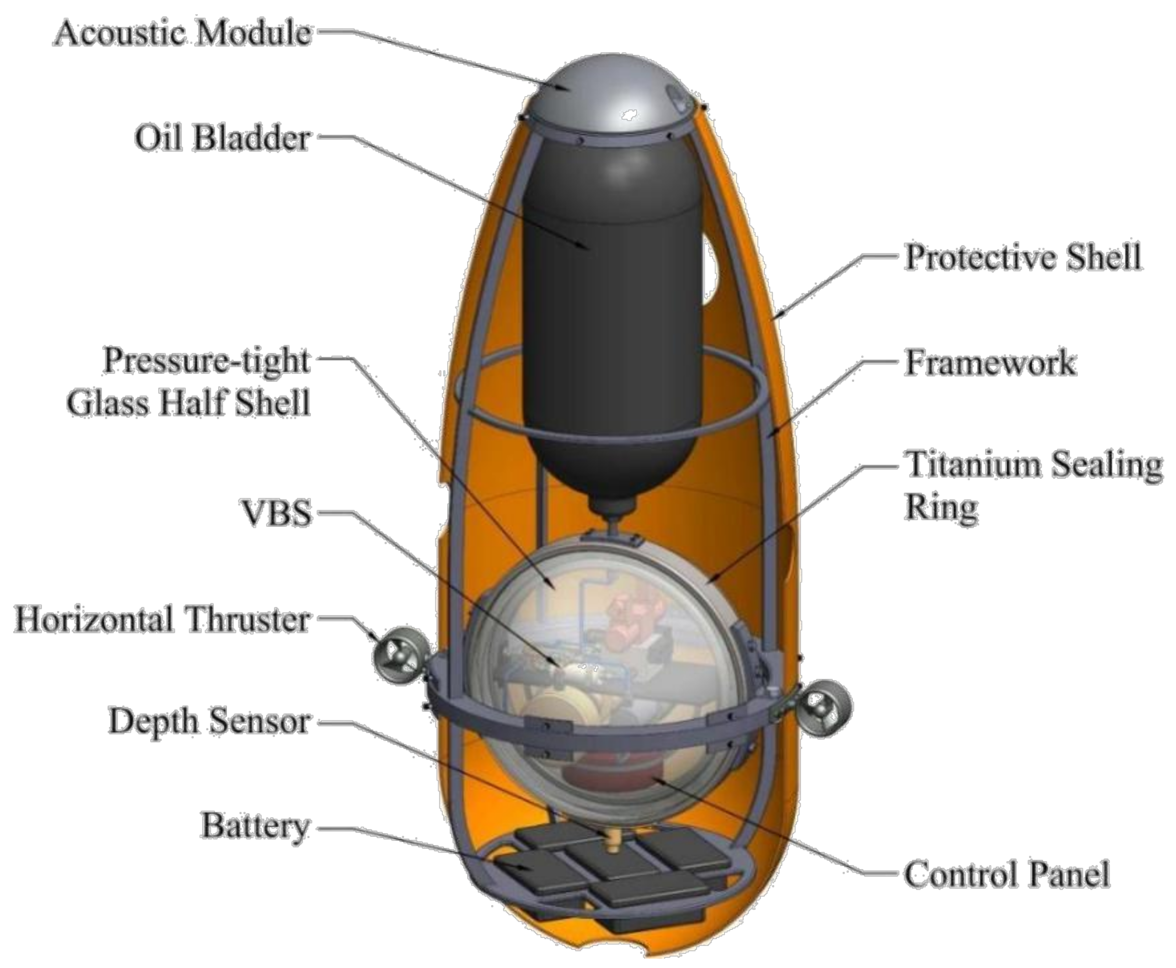
2.1. System Description
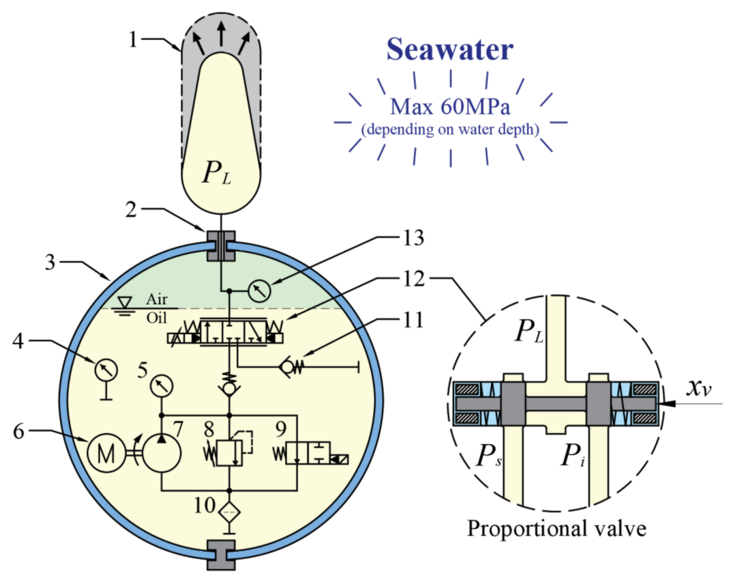
The proposed deep-sea AUV mainly comprises a protective shell, framework, acoustic module, batteries, horizontal thruster, pressure-tight glass half-shells, titanium ring, VBS, and oil bladder. Figure 1 shows its inner structure view, where two pressure-tight glass half-shells are sealed by a titanium ring to protect the oil submerged hydraulic VBS and the control panel from colossal water pressure. Typically, a titanium pressure-tight shell is used to protect the inner system of most underwater vehicles. However, titanium alloy is expensive and difficult to manufacture, for which two pressure-tight half-shells made of cheaper and lighter high borax glass are used in this paper. The batteries, encapsulated in oil to resist water pressure, are installed in the lower layer of the framework to supply power, and are also used to stabilize the center of gravity. During AUV working, the VBS pumps oil into the bladder to increase total buoyancy, for when the AUV floats up; on the contrary, the hydraulic system allows external water pressure to extrude the oil back to the VBS from the bladder to decrease total buoyancy, for when the AUV floats down.
In the calculation, the volume of external devices, such as the acoustic module, thrusters, and batteries, are negligible in the dynamic modeling since they are relatively small compared to the glass shell and oil bladder. The oil is assumed not to be compressed. In addition, the density changes of oil and air with temperature are ignored. The main designed parameters of the proposed AUV are shown in Table 2.

2.2. Hydraulic VBS

For a deep-sea VBS, hydraulic power is necessary due to the huge water pressure. Figure 2 shows the hydraulic schematic diagram of the proposed VBS. The whole hydraulic system is submerged in oil and isolated from seawater by the glass pressure-tight shell. In order to ensure that the oil can be drained normally, some air should be filled into the shell and pressurized to reduce the pressure difference between the outer and inner parts of the shell. The radial piston pump driven by a constant speed BLDC motor supplies oil with a constant flow rate as the power source. In order to regulate the flow rate of oil into or out of the oil bladder, an electro-hydraulic proportional reversing valve is used to achieve continuous regulation. When the AUV sinks into deep water, the control panel can adjust the displacement of the valve spool to fill, discharge, or cut off the oil supply. The main operating principle of the VBS is as follows: If the valve spool moves positively, the bladder will be filled to increase buoyancy. The hydraulic system needs to overcome external pressure to fill oil into the bladder, for which the relief valve is set to keep the oil from having enough back pressure against the seawater. If the valve spool moves in reverse, the oil will be squeezed back to the VBS by the water pressure, buoyancy decreasing.
Assuming the spool and orifice of the proportional valve have ideal geometry, for an open valve, the flow rate passing through it is not only related to the displacement of the spool but also related to the pressure difference on both sides [46,47]. Due to the oil bladder contacting with seawater directly, the oil pressure in the bladder can be considered equal to the water pressure PL, which increases with the water depth h and can be expressed as
P L = ρ s e a g h ,
where ρsea is the seawater density function varying with the water depth coming from the observational data of the South China Sea, which is given by Equation (2). Additionally, the change of seawater density is also the main factor that causes the system time-varying which enhances the design difficulty of the controller.
ρ s e a h =   1020.56   kg / m 3 0 < h < 66.37   m 26.13 e 4.674 × 10 5 h 11.36 e 0.01052 h + 1000   kg / m 3 h 66.37   m
In order to drain oil out of the VBS, some volume of air should remain inside the glass shell. Assuming that the inside air is an ideal gas with a pre-charged pressure of Pi0 and an initial volume of Vi0, with the oil flow out, the air pressure Pi and volume Vi will be changed, and their relationship can be described by Boyle’s law as
P i 0 V i 0 n = P i V i n = P i V i 0 0 t q L d t n ,
where n is the adiabatic exponent of air, qL is the flow rate of the oil flow through the valve, and t is the time start from depth control. By sorting Equation (3), the inner oil pressure, which is also the air pressure, can be given by
P i = P i 0 V i 0 V i 0 0 t q L d t n ,
Then the mathematical relationship between the output flow rate and the displacement of the valve spool can be described as
q L = C d ω x v 2 Δ P v ρ o i l ,
where Cd is the valve orifice flow coefficient, ω is the throttle area gradient, xv is the displacement of the valve spool, and the pressure difference of the proportional valve ΔPv can be expressed as
Δ P v = P s P L x v 0 P L P i x v < 0 ,
where Ps is the source pressure determined by the relief valve.
Since the bandwidth of the proportional valve is high enough, a common assumption is made in many similar works that the dynamic of the valve spool can be neglected [48,49]. The simplified relationship between the spool displacement and the control voltage can be expressed as
x v = k i u i ,
where ki is the dynamic proportional coefficient of the valve, ui is the control voltage. Then, by inserting Equation (7), Equation (5) can be further expressed as
q L = K v u i Δ P v ,
with K v = C d ω k i 2 ρ o i l .

2.3. AUV Dynamic Model

2.3.1. Assumptions

The motion of an underwater vehicle can be decomposed into six independent degrees of freedom, namely three translations of surge, sway, and heave, and three rotations of roll, pitch, and yaw. In this paper, the depth of the AUV is the main control target. Hence only the heave motion of AUV needs to be concerned in the mathematical modeling. To simplify the mathematical model, several simplifications were made for numerical simulations of the AUV motion, which were as follows:
  • The motion of the AUV in surge, sway, roll, pitch, and yaw directions was neglected;
  • The oil bladder was filled with about 20 L (half of the total volume) of oil to balance gravity. The AUV had neutral buoyancy;
  • The origin of the body-fixed coordinate of the AUV was located at its center of gravity, which is also the ball center of the glass shell.

2.3.2. Mathematical Model

A deep-sea AUV is mainly subjected to four forces, i.e., buoyancy, water resistance, disturbance, and gravity. According to Newton’s second law, the dynamic equation can be obtained as
M δ ¨ = B W R + d ,
where M = m + madd, m is the total mass of AUV, madd is the added mass, δ ¨ is the depth, W is gravity, B is the total buoyancy, R is the water resistance, and d is the disturbance force.
Here, the added mass comes from the mass of the surrounding water driven by the unsteady movement of the vehicle. For an approximately spherical VBS, the calculation formula of its added mass is given by
m a d d = 1 2 ρ sea V s ,
where Vs = 4/3πr3 is the volume of the spherical VBS, and r is its radius. The water resistance is caused by the liquid viscosity, which can be calculated by
R = 1 2 C D ρ s e a δ ˙ δ ˙ A s ,
where CD is the flow coefficient related to the Reynolds number and the geometry shape [50], As = πr2 is the cross-section area of a sphere. The flow coefficient is usually estimated as CD = 0.4 for an ellipsoidal underwater vehicle [51].
Assuming the oil bladder has been filled with a little oil to counteract the gravity of AUV after diving, based on this premise, the VBS could regulate the residual buoyancy by adding or removing oil in the oil bladder. Therefore, the gravity and initial drainage volume of the AUV could be ignored in the analysis. The residual buoyancy of AUV is denoted by Br, which can be described as
B r = B W = ρ s e a g o t q L d t ,
where δ is the depth of AUV, g is the acceleration of gravity.
After eliminating the influence of gravity, the gravity balanced dynamic model for AUV depth control can be expressed as
M δ ¨ = B r R + d ,
In order to simplify the controller design, the system dynamic equation needs to be transformed into a state-space equation. However, the residual buoyancy Br is an integral term about the flow rate qL, which means the dynamic equation is not the simplest. By inserting Equations (8), (11), and (12) into Equation (13) and differentiating it, the integration could be eliminated. The new third-order dynamic equation can be expressed as
M δ = K v ρ s e a g Δ P v u i C D ρ s e a A s δ ˙ δ ¨ + d ˙ ,
Therefore, choosing the system state variable as: x = δ δ ˙ δ ¨ T . According to Equation (14), the state-space equation and output equation of the proposed AUV system are given by
x ˙ = x ˙ 1 x ˙ 2 x ˙ 3 = x 2 x 3 f 1 x 2 , x 3 + f 2 Δ P v u i + D ,
y = 1 0 0 x ,
with f 1 x 2 , x 3 = C D ρ s e a A s M x 2 x 3 , f 2 Δ P v = K v ρ s e a g M Δ P v , and D = d ˙ M .
Equation (16) shows that the dynamic system of the proposed AUV has properties of non-linear, time-varying, and high-order, which enhance the design requirements of the depth controller. In the numerical simulation sections, the AUV system is established by MATLAB/Simulink to test the performance of the designed controllers. The major parameters it uses are listed in Table 3.

3. Controller Design

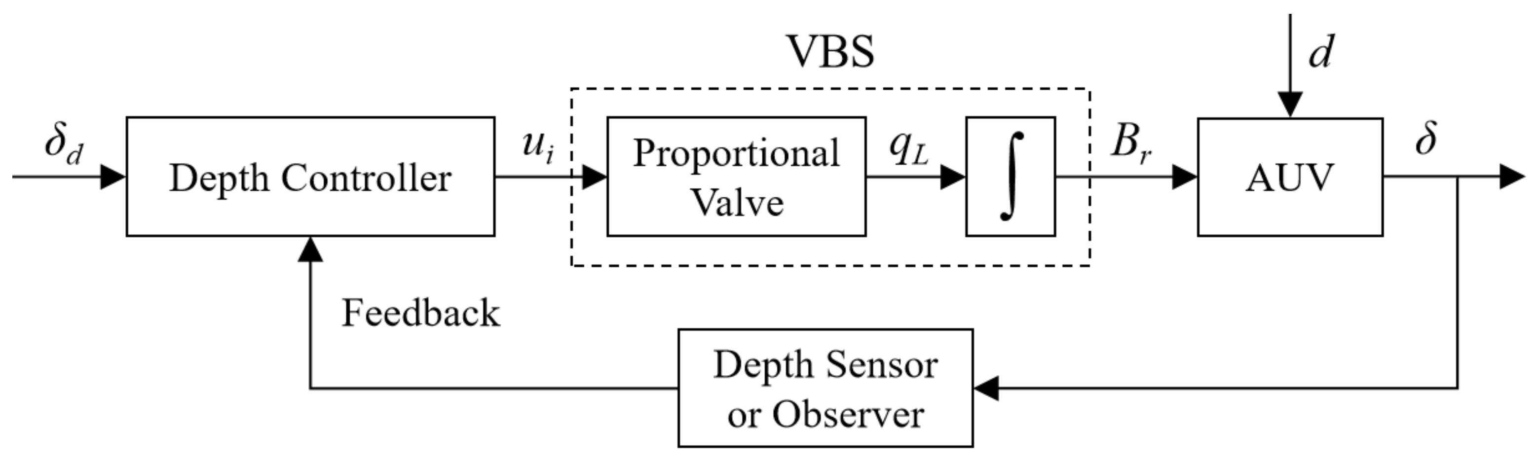
3.1. Depth Control Principle

The depth control for an AUV is realized by its VBS and depth controller. Figure 3 shows the control diagram for AUV depth control, in which the VBS is an actuator that drives the AUV to achieve heave motion. The depth controller takes the expected depth δd as input. By measuring the AUV depth with a depth sensor or observing the system states to form a closed-loop system, the controller can continuously adjust the AUV to arrive at the expected depth.
Assuming the actual depth of AUV can be accurately measured by a depth sensor without noise, additionally, the non-linear features of the proportional valve and the variation of seawater density can be ignored in the process of controller designing. However, they are established in the system simulation and serve as a test of controller robustness. The seawater density is regarded as a constant value of ρsea = 1024 kg/m3. The flow rate of the proportional valve is regarded as a linear relationship with the input voltage thereof, which is
q L = K u i ,
where K is the linear gain of the proportional valve from its input voltage to output flow rate. By inserting Equation (17) into Equation (15), the system state-space equation for controller designing is
x ˙ = x ˙ 1 x ˙ 2 x ˙ 3 = x 2 x 3 f 1 x 2 , x 3 + K i u i + D ,
with K i = K ρ s e a g M .
Section 3.2, Section 3.3 and Section 3.4 will propose different depth controllers for comparing the control performance, including conventional PID controller, LADRC controller, and fuzzy LADRC controller. Their design processes and analysis are as follows.

3.2. PID Controller

PID is the most extensively used control method in the industry. It takes the deviation between the expected and feedback signal as input, output, the sum of the deviation, deviation integral, and deviation differential. The PID control law of the depth control for AUV is expressed as
u i = K P e + K I 0 t e d t + K D e ˙ ,
where KP, KI, and KD are the controller gains of proportional, integral, and differential, respectively, and e = δ d δ is the feedback error.

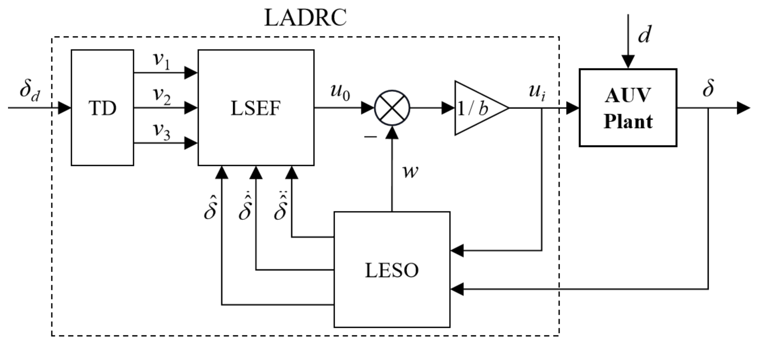
3.3. Linear Active Disturbance Rejection Controller (LADRC)

ADRC is a control method that aims to observe the total disturbances of the system and eliminate them [52]. The stability analysis for this control method can be found in many studies [53,54], hence it is not dealt with in this paper. Figure 4 shows the control diagram of a third-order linear ADRC controller. There are three main parts in the controller, tracking differentiator (TD), linear extended state observer (LESO), and linear state error feedback control law (LSEF), by which the depth of AUV can be controlled. They are respectively presented as follows.

3.3.1. Tracking Differentiator (TD)

TD is a dynamic system that aims to track the expected input, arrange the transition process, and give high-order differentials. A step signal with the expected depth is generally and used as an input signal during the depth control process. However, it may abruptly increase the controller output to achieve saturation, so arranging a transition process can alleviate this sudden change.
For the third-order system of Equation (15), a third-order ADRC controller is chosen to stabilize its whole states. Therefore, a third-order TD is also needed to match the controller. Equation (20) gives a simple third-order system without overshoot, suitable as the required TD [55].
T D 3 s = r 3 s + r 3 ,
where r is named as the speed factor. From Equation (18), its state-space equation is expressed as
v ˙ = 0 1 0 0 0 1 r 3 3 r 2 3 r v + 0 0 r 3 δ d ,
with v = [v1 v2 v3]T, where v1, v2, and v3 are the tracking value, first-order differential, and second-order differential of the expected depth, respectively.

3.3.2. Linear Extended State Observer (LESO)

As the most critical part of an ADRC controller, the extended state observer is used to observe the system states, in the meantime, estimate the total disturbance in the system and extend it to a higher-order new state [56,57]. Total disturbance includes unmodeled dynamics and internal and external disturbances. For the system described by Equation (18), the LESO can be designed as
z ^ ˙ = A z ^ + B u i + β e ^ o ,
with z ^ = δ ^ δ ^ ˙ δ ^ ¨ w , A = 0 1 0 0 0 0 1 0 0 0 0 1 0 0 0 0 , Β = 0 0 b 0 , and β = β 1 β 2 β 3 β 4 , where δ ^ is the observed value of the AUV depth, w is the total disturbance, b is the input gain, β1, β2, β3, and β4 are the observer gains, and e ^ o = δ δ ^ is the observing error. According to [53], all the observer poles could be arranged at ωo named as the observer bandwidth, then the observer gains can be expressed as functions of ωo, that is
β = 4 ω o 6 ω o 2 3 ω o 3 ω o 4 T ,
This formula reduces the number of uncertain parameters in LESO from five to two (ωo and b), making parameter tuning easier. Here, the observer bandwidth ωo determines the convergence speed of LESO. The higher it is, the faster the LESO becomes stable, but it is easier to amplify the noise. Additionally, the input gain b should be as similar to the original system as possible, chosen as b = Ki in this paper.
When LESO achieves stability, the depth, speed, and acceleration of AUV will be observed, the total disturbance will tend to w f 1 ( x 2 , x 3 ) + D and can be eliminated by taking the controller output as
u i = u o w b ,
After that, the dynamic system of Equation (18) is compensated to a third-order integrator, which can be controlled by full state feedback.

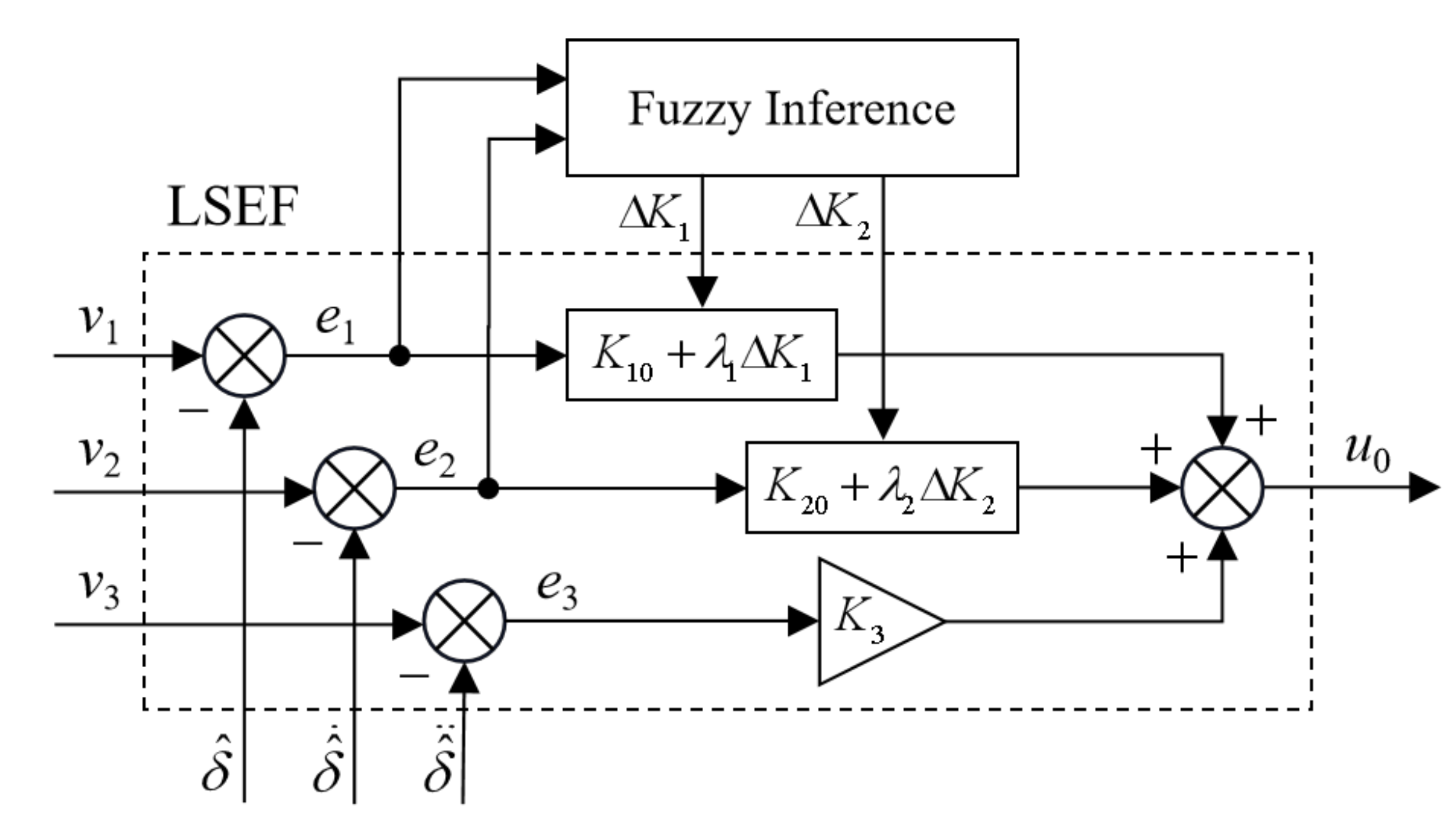
3.3.3. Linear State Error Feedback (LSEF) Control Law

For the third-order integrator after compensation, the LSEF control law could be expressed as
u o = K 1 v 1 δ ^ + K 2 v 2 δ ^ ˙ + K 3 v 3 δ ^ ¨ ,
where K1, K2, and K3 are the feedback gains of depth, speed, and acceleration, respectively.

3.4. Fuzzy LADRC Controller (F-LADRC)

In order to enhance the performance of the LADRC controller, a fuzzy logic method was designed for the LSEF of Section 3.3.3 to allow time-variable tuning of the depth and speed feedback gains. The block diagram of the designed fuzzy LSEF is as shown in Figure 5, in which the depth and speed feedback gains could be calculated by
K 1 = K 10 + λ 1 Δ K 1 K 2 = K 20 + λ 2 Δ K 2 ,
where K10 and K20 are the initial feedback gains of controller, λ1 and λ2 are the correction factors which are used to adjust the influence from the fuzzy rules to the controller, ΔK1 and ΔK2 are the adaptive parameters used for regulating the values of K1 and K2 by the fuzzy inference part.
The fuzzy inference part takes the input of the depth error e1 and speed error e2, and ΔK1 and ΔK2 as outputs. Due to the acceleration feedback only being used to suppress the high-order dynamic of the system, a fuzzy adjustment is not needed for it. According to the fuzzy logic methods, the fuzzy inference part can dynamically tune the feedback gains of LSEF control law to adapt to the actual requirement of the controller.
The fuzzy inference is constructed by the fuzzy rules and the membership functions. The fuzzy rules are shown in Table 4, in which negative big (NB), negative middle (NM), negative small (NS), zero (ZO), positive small (PS), positive middle (PM), and positive big (PB) are the fuzzy subsets used to describe the fuzzy domains of input and output variables. For example, when e1 is characterized as NB and e2 is characterized as PB, then the corresponding table entry ZO/PS indicates the fuzzy values returned for ΔK1 and ΔK2, respectively. The relationship can also be indicated by a fuzzy rule: if e1 is NB and e2 is PB, then ΔK1 is ZO and ΔK2 is PS. In this paper, all fuzzy domains are chosen for the unit range [−1, 1] as they are easy to match the system requirement by regulating the correction factors. Additionally, the membership functions of the input and output variables are chosen as triangular types. The fuzzy inference process contains the following steps:
  • Converts the input values e1 and e2 to the fuzzy subsets by membership functions;
  • Returns the output fuzzy subsets according to the fuzzy rules;
  • Converts the output fuzzy subsets to output values ΔK1 and ΔK2.
Table 4. Fuzzy rules for ΔK1 and ΔK2 with inputs e1 and e2.
ΔK1K2e2
e1NBNMNSZOPSPMPB
NBNB/PSNB/NSNM/NBNM/NBNS/NBNS/NMZO/PS
NMNB/PSNB/NSNM/NBNS/NMNS/NMZO/NSPS/ZO
NSNM/ZONM/NSNM/NMNS/NMZO/NSPS/NSPM/ZO
ZONM/ZONM/NSNS/NSZO/NSPS/NSPM/NSPM/ZO
PSNM/ZONS/ZOZO/ZOPS/ZOPM/ZOPM/ZOPM/ZO
PMNS/PBZO/NSPS/PSPS/PSPM/PMPB/PMPB/PB
PBZO/PBPS/PMPS/PMPM/PMPM/PSPB/PSPB/PB

4. Simulation Results and Analysis

The three controllers designed in Section 3, including PID controller, LADRC controller, and fuzzy LADRC controller, are implemented and studied with MATLAB/Simulink. Taking the AUV system described in Section 2 as a controlled plant, the depth control performance can be compared. In addition, the anti-interference ability of each controller is also tested by exerting disturbance forces on the AUV. To make sure the comparison results are reliable, all the controllers were already tuned before simulation. The control parameters are listed in Table 5. The fuzzy LADRC controller has the same basic parameters as the LADRC controller but differs in the fuzzy inference part.

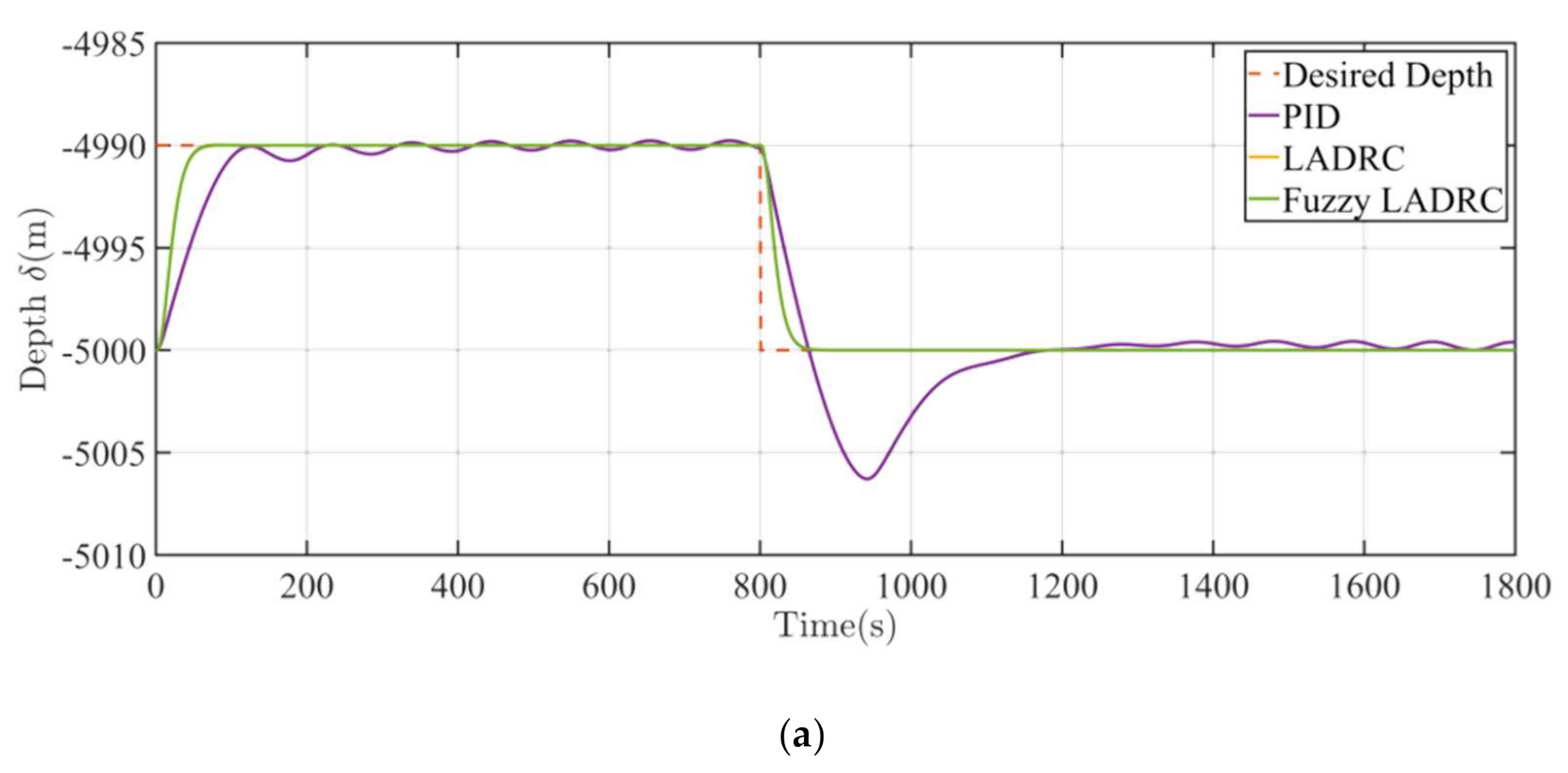
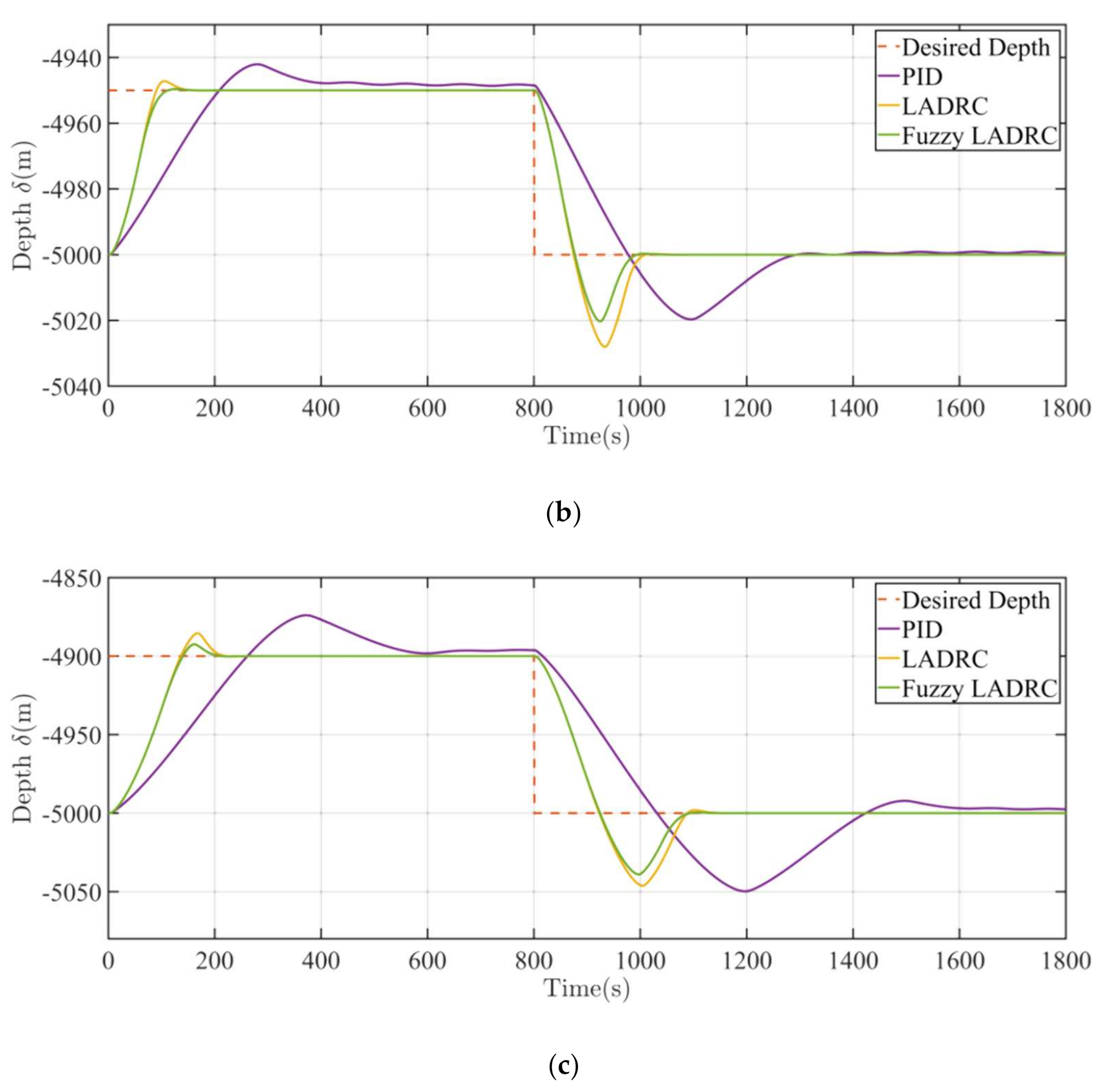
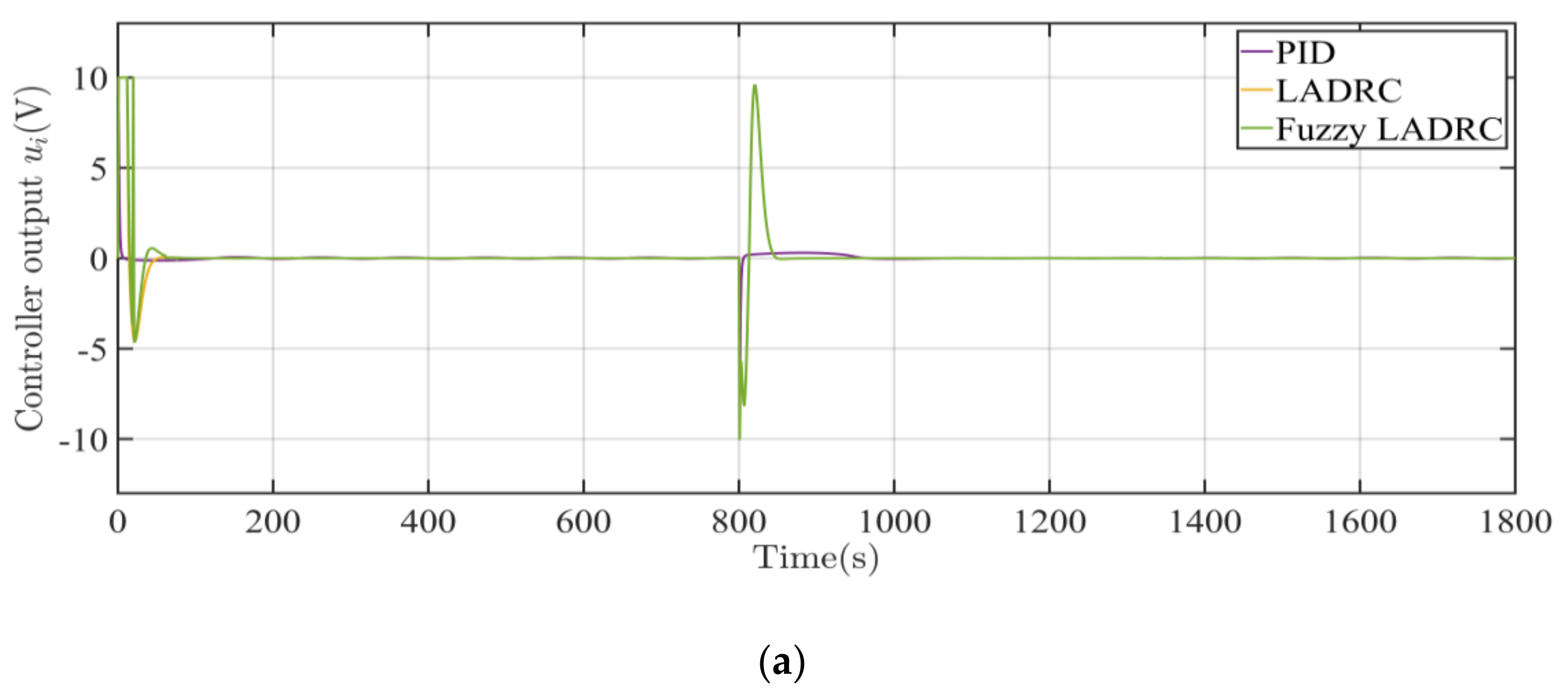
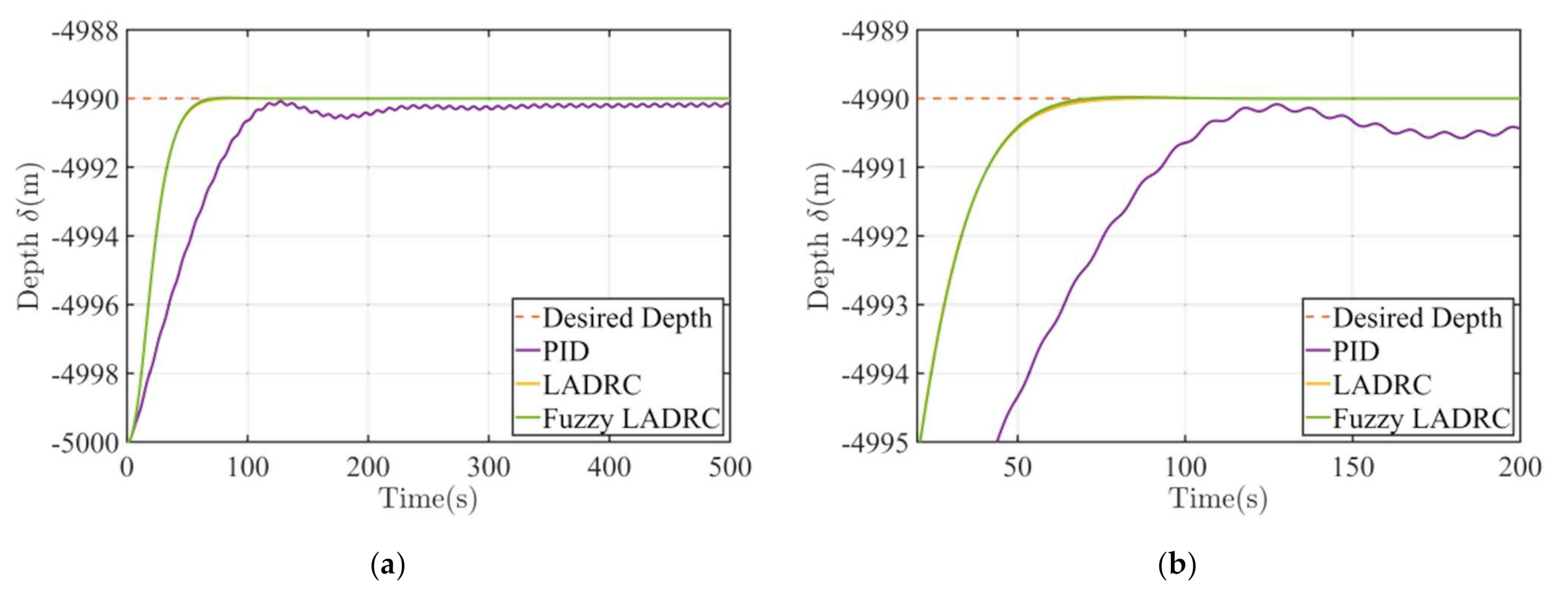
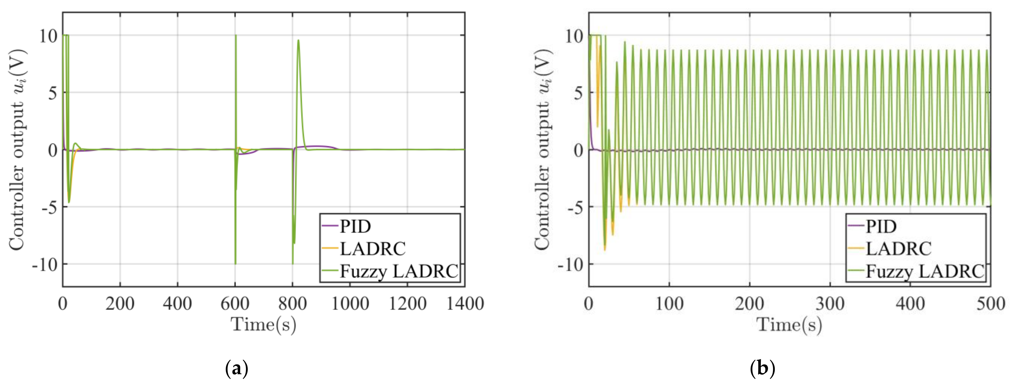
4.1. Without Disturbance

Assuming the AUV has already dived in a water depth of 5000 m, to test the performance of the designed depth controllers, three step signals with different desired depths are applied in the numerical simulations. The desired depths are respectively set at 4990 m, 4950 m, and 4900 m at the first 800 s, then return to 5000 m again. Each simulation lasts for 1800 s.
The depth control response curves of the AUV system with PID, LADRC, and fuzzy LADRC controllers are shown in Figure 6a–c, which indicates that the ADRC type controllers are better than the PID controller in entirety. It can be seen from the figures that the curves of the PID controller oscillate around the desired depths after arriving at them, and the reason is that the PID controller cannot stabilize the high order dynamic of the AUV system due to its second-order feature. At the same time, the LADRC and fuzzy LADRC controllers can well suppress such oscillations. Moreover, the steady-state errors of the PID controller in the first to third figures increase with the target distance. The reason is that the water density reduces with the decreasing depth of AUV, which rather decreases the buoyancy received by the AUV. Therefore, when the depth decreases, it is easier for the AUV to flow upwards, which manifests as the steady-state error of the PID controller increasing with the target distance. In contrast, the curves of the two ADRC controllers all achieve corresponding target depths rapidly without steady-state errors. Another notable point in Figure 6 is that when diving the AUV has a more severe overshoot than when ascending. The reason is that the buoyancy of the VBS changes faster when the AUV is diving. The hydraulic VBS works passively and whose buoyancy when changing speed mainly depends on the external water pressure. The huge external pressure shrinks the oil bladder and makes the AUV lose buoyancy rapidly, which manifests as diving overshoot. Despite this, the ADRC controllers still perform well.
Figure 7a–c shows the control outputs of the PID, LADRC, and fuzzy LADRC controllers corresponding to the three target depths in Figure 6a–c, respectively. It can be seen that the better performance of the two ADRC controllers is due to the fact that they have more aggressive outputs, compared to the PID controller. When the target depth changes, the two controllers regulate the system rapidly and even their outputs reach saturation. The saturation is acceptable since there is no integral control in the ADRC controller. For further comparison, characteristic response parameters obtained from the first 800 s of the simulations are presented in Table 6.
Compared with the PID controller, the LADRC controller can achieve better performance with the rise time reduced by at least 54.9%, the settling time reduced by at least 64.1%, the maximum overshoot reduced by at least 43.8%, and without steady-state error. Moreover, compared with the LADRC controller, the maximum overshoot of the fuzzy LADRC controller is further reduced by at least 48.5%. To sum up, the simulation results indicate that in the depth control of the AUV without disturbance, the performance of the ADRC type controllers is significantly better than the conventional PID controller. Furthermore, the fuzzy LADRC controller performs better at suppressing overshoot caused by the time-varying and non-linear features in the AUV system than the LADRC controller.

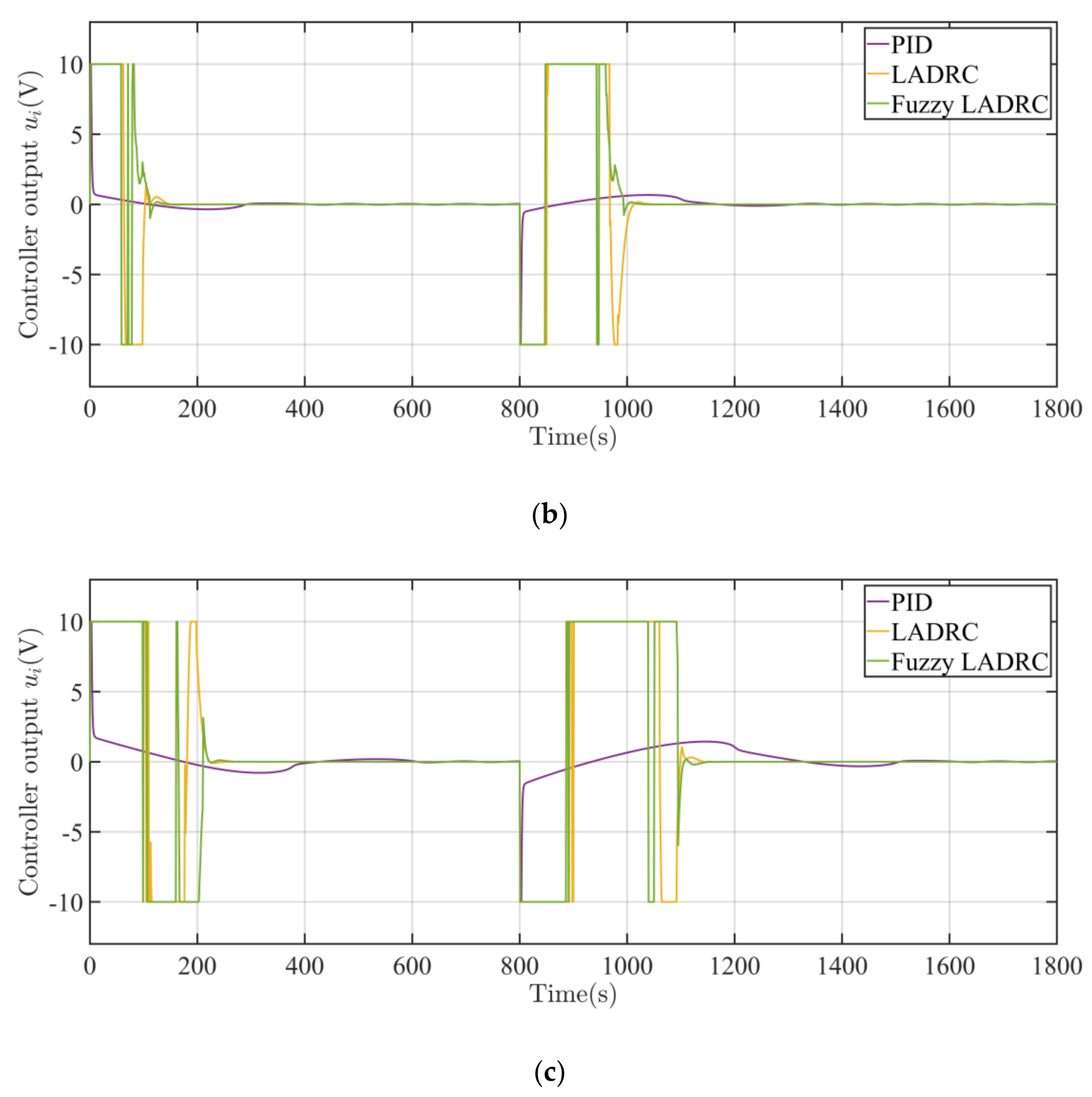
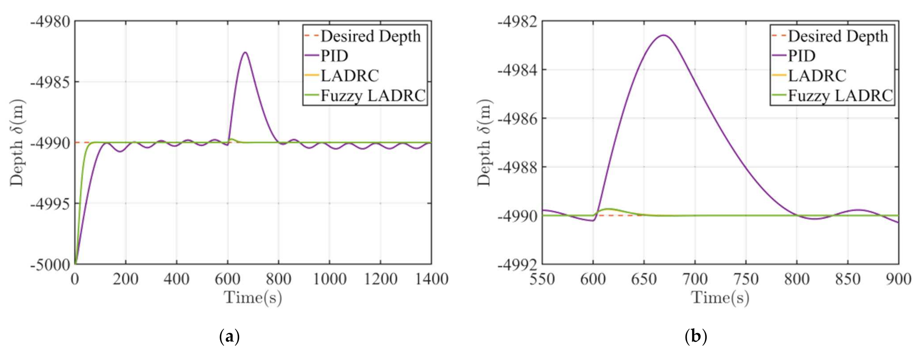
4.2. With Disturbance

Deep-sea AUV may be subject to various uncertain interferences from sudden currents and mass changes. To analyze the anti-interference ability of the three designed controllers, two types of disturbances include step force and sine force, are considered.
The response curves of the three controllers in the presence of the static disturbance force are shown in Figure 8. An upward step force of 5 N is imposed on the AUV in the 600th second to study its mass changing. It can be seen from the figure that the ADRC type controllers have better anti-interference ability and adaptability than the PID controller. Both ADRC controllers have similar response curves with a maximum rising distance of 0.27 m, which is much lower than the value of the PID controller, 7.41 m.
Moreover, the response curves of the three controllers in the presence of the sine disturbance force given by Equation (27) are shown in Figure 9, with their corresponding characteristic parameters being summarized in Table 7. The disturbance period is chosen as 10 s since it is in the common current period range of about 7~12 s. Due to the existence of the sine disturbance force, the steady-state error of each curve should be estimated on average. It can be found from the figures and table that the ADRC type controllers are unaffected by the disturbance force. However, the disturbance force causes a tiny oscillation on the PID controller’s curve and worsens its performance.
d = 2 sin 0.2 π t ,
Figure 10a,b show the controller outputs when the system faces the two types of disturbance, respectively. It can be seen from Figure 10a that the ADRC controllers can quickly adjust the system from the effect of disturbance. Moreover, Figure 10b shows how the ADRC controllers compensate for the influence of sine disturbance on the system, which proves that the designed controllers are efficient and reliable when facing disturbance.
To further quantify the influence of the disturbance force on the controllers, the corresponding characteristic parameters in Table 6 and Table 7 were compared, and their changes are shown in Table 8. The parameter changes of the LADRC and fuzzy LADRC controllers are less than that of the PID controller. Only the settling time of the PID controller changes significantly because of the disturbance. Therefore, the designed LADRC and fuzzy LADRC controllers have a better anti-interference capability and robustness when facing static or sine disturbance.

5. Conclusions

This paper proposes a deep-sea AUV with oil bladder type VBS. The mathematical model of the hydraulic VBS and the dynamic model of AUV was established, considering the variation of seawater density with depth, and the non-linear features of the proportional valve and inner air pressure. According to the system model, three depth controllers including PID controller, LADRC controller, and fuzzy LADRC controller were designed and implemented with MATLAB/Simulink. By simulating the processes of rising and diving in deep water with and without disturbance forces, the three controllers’ control performance and anti-interference capability were compared. The results demonstrate that in both cases, the LADRC and fuzzy LADRC controllers could rapidly achieve the desired depth with small rise time, settling time, steady-state error, and overshoot, which indicates they have advantages of high accuracy and fast response. In addition, compared with the LADRC controller, the fuzzy LADRC controller could better suppress the overshoot caused by the non-linear and time-varying features of the system. Both ADRC type controllers perform excellently in the anti-interference aspect, no matter whether facing a step disturbance or a sine disturbance. They can quickly adapt to the disturbance and re-stabilize the AUV depth with nearly no steady-state errors and overshoots. Therefore, it can be concluded that the designed LADRC controller and fuzzy LADRC controller could satisfy the depth control requirements of the proposed deep-sea AUV. The fuzzy LADRC controller could further decrease the overshoot of AUV depth and improve the control performance.
In the practical application of depth control for the similar deep-sea AUV, if the computing power of the onboard processor is not sufficient to support fuzzy inference programs, the LADRC controller can also achieve good control performance. If both better depth response performance and lower overshoot are required, a fuzzy LADRC controller with a high-performance processor is essential. In the next step of our work, a maritime experiment of depth control for the proposed deep-sea AUV system will be carried out to test its practical performance.

Author Contributions

Data curation, D.N.; Methodology, J.H.; Supervision, Y.G.; Writing—review and editing, F.Z. All authors have read and agreed to the published version of the manuscript.

Funding

This research was funded by National Nature Science Foundation of China (52075064, U1908228), Dalian Innovation Program (2018RQ19) and Fundamental Research Funds for the Central Universities.

Institutional Review Board Statement

Not applicable.

Informed Consent Statement

Not applicable.

Data Availability Statement

Not applicable.

Conflicts of Interest

The authors declare no conflict of interest.

References

  1. Howell, S.M.; Stone, W.C.; Craft, K.; German, C.; Murray, A.; Rhoden, A.; Arrigo, K. Ocean Worlds Exploration and the Search for Life. arXiv 2020, arXiv:2006.15803. [Google Scholar] [CrossRef]
  2. Auzende, J.M.; Bideau, D.; Bonatti, E.; Cannat, M.; Honnorez, J.; Lagabrielle, Y.; Malavieille, J.; Mamaloukas-Frangoulis, V.; Mével, C. The MAR-Vema Fracture Zone intersection surveyed by deep submersible Nautile. Terra Nova 1990, 2, 68–73. [Google Scholar] [CrossRef]
  3. Liu, Y.; Liu, X.; Lv, X.; Cao, W.; Sun, C.; Lu, J.; Wang, C.; Lu, B.; Yang, J. Watermass properties and deep currents in the northern Yap Trench observed by the Submersible Jiaolong system. Deep Sea Res. Part I Oceanogr. Res. Pap. 2018, 139, 27–42. [Google Scholar] [CrossRef]
  4. Aguiar, A.P.; Almeida, J.; Bayat, M.; Cardeira, B.; Cunha, R.; Häusler, A.; Maurya, P.; Oliveira, A.; Pascoal, A.; Pereira, A.; et al. Cooperative control of multiple marine vehicles theoretical challenges and practical issues. IFAC Proc. Vol. 2019, 42, 412–417. [Google Scholar] [CrossRef] [Green Version]
  5. Liu, Y.; Anderlini, E.; Wang, S.; Ma, S.; Ding, Z. Ocean Explorations Using Autonomy: Technologies, Strategies and Applications. In Offshore Robotics; Springer: Singapore, 2022; pp. 35–58. [Google Scholar] [CrossRef]
  6. Gafurov, S.A.; Klochkov, E.V. Autonomous unmanned underwater vehicles development tendencies. Procedia Eng. 2015, 106, 141–148. [Google Scholar] [CrossRef] [Green Version]
  7. Nolet, G. MERMAID seismometry in the oceans: Resolving the detail of geodynamic processes. In Proceedings of the EGU General Assembly Conference Abstracts, Vienna, Austria, 17–22 April 2016. [Google Scholar]
  8. Hussain, N.A.A.; Arshad, M.R.; Mohd-Mokhtar, R. Underwater glider modelling and analysis for net buoyancy, depth and pitch angle control. Ocean. Eng. 2011, 38, 1782–1791. [Google Scholar] [CrossRef]
  9. Jensen, H.F. Variable Buoyancy System Metric. Ph.D. Thesis, Massachusetts Institute of Technology, Cambridge, MA, USA, 2009. [Google Scholar]
  10. Rigaud, V.; Nicolas-Meunier, B. From manned to autonomous and hybrid underwater systems. In Proceedings of the 2015 IEEE Underwater Technology, Chennai, India, 23–25 February 2015; IEEE: Piscataway, NJ, USA, 2010; pp. 1–10. [Google Scholar] [CrossRef]
  11. Rona, P.A. Deep-diving manned research submersibles. Mar. Technol. Soc. J. 1999, 33, 13–25. [Google Scholar] [CrossRef]
  12. Schneider, W.E. Alvins oil-seawater hydraulics overcomes 6000-psi backpressure. Hydraul. Pneum. 1975, 28, 61–63. [Google Scholar]
  13. Nanba, N.; Morihana, H.; Nakamura, E.; Watanabe, N. Development of deep submergence research vehicle “SHINKAI 6500”. Tech. Rev. Mitsubishi Heavy Ind. Ltd. 1990, 27, 157–168. [Google Scholar]
  14. Komuku, T.; Matsumoto, K.; Imai, Y.; Sakurai, T.; Ito, K. 1000 Dives by the Shinkai 6500 in 18 Years. In Proceedings of the 2007 Symposium on Underwater Technology and Workshop on Scientific Use of Submarine Cables and Related Technologies, Tokyo, Japan, 17–20 April 2007; IEEE: Piscataway, NJ, USA, 2007; pp. 21–27. [Google Scholar] [CrossRef]
  15. Qiu, Z. Design and research on a variable ballast system for deep-sea manned submersibles. J. Mar. Sci. Appl. 2008, 7, 255–260. [Google Scholar] [CrossRef]
  16. Cui, W. An overview of submersible research and development in China. J. Mar. Sci. Appl. 2018, 17, 459–470. [Google Scholar] [CrossRef]
  17. Liu, Y.; Wu, D.; Li, D.; Zhao, X. Seawater hydraulic buoyancy adjusting system for large-depth submersible. Chin. Hydraul. Pneum. 2014, 38, 1–10. (In Chinese) [Google Scholar] [CrossRef]
  18. Liu, F.; Cui, W.; Li, X. China’s first deep manned submersible, JIAOLONG. Sci. China Earth Sci. 2010, 53, 1407–1410. [Google Scholar] [CrossRef]
  19. Zhao, X.; Liu, Y.; Han, M.; Wu, D.; Li, D. Improving the performance of an AUV hovering system by introducing low-cost flow rate control into water hydraulic variable ballast system. Ocean. Eng. 2016, 125, 155–169. [Google Scholar] [CrossRef]
  20. Choyekh, M.; Kato, N.; Yamaguchi, Y.; Dewantara, R.; Senga, H.; Chiba, H.; Yoshie, M.; Tanaka, T.; Kobayashi, E. Depth Control of AUV Using a Buoyancy Control Device. In Mechatronics and Robotics Engineering for Advanced and Intelligent Manufacturing; Springer: Cham, Switzerland, 2017; pp. 431–444. [Google Scholar] [CrossRef]
  21. Xu, J.A.; Zhang, M.J. A variable buoyancy system for long cruising range AUV. In Proceedings of the 2010 International Conference on Computer, Mechatronics, Control and Electronic Engineering, Changchun, China, 24–26 August 2010; IEEE: Piscataway, NJ, USA, 2010; Volume 2, pp. 585–588. [Google Scholar] [CrossRef]
  22. Busquets-Mataix, J.; Busquets-Mataix, J.V.; Busquets-Mataix, D. Combined gas-fluid buoyancy system for improved attitude and maneuverability control for application in underwater gliders. IFAC-PapersOnLine 2015, 48, 281–287. [Google Scholar] [CrossRef]
  23. Petritoli, E.; Leccese, F.; Cagnetti, M. A high accuracy buoyancy system control for an underwater glider. In Proceedings of the 2018 IEEE International Workshop on Metrology for the Sea, Learning to Measure Sea Health Parameters (MetroSea), Bari, Italy, 8–10 October 2018; IEEE: Piscataway, NJ, USA, 2019; pp. 257–261. [Google Scholar] [CrossRef]
  24. Petritoli, E.; Leccese, F.; Cagnetti, M. High accuracy buoyancy for underwater gliders: The uncertainty in the depth control. Sensors 2019, 19, 1831. [Google Scholar] [CrossRef] [PubMed] [Green Version]
  25. Asakawa, K.; Watari, K.; Ohuchi, H.; Nakamura, M.; Hyakudome, T.; Ishihara, Y. Buoyancy engine developed for underwater gliders. Adv. Robot. 2016, 30, 41–49. [Google Scholar] [CrossRef]
  26. Zhou, H.; Fu, J.; Liu, C.; Zeng, Z.; Yu, C.; Yao, B.; Lian, L. Dynamic modeling and endurance enhancement analysis of deep-sea gliders with a hybrid buoyancy regulating system. Ocean. Eng. 2020, 217, 108146. [Google Scholar] [CrossRef]
  27. Inoue, T.; Shibuya, K.; Nagano, A. Underwater robot with a buoyancy control system based on the spermaceti oil hypothesis development of the depth control system. In Proceedings of the 2010 IEEE/RSJ International Conference on Intelligent Robots and Systems, Taipei, Taiwan, 18–22 October 2010; IEEE: Piscataway, NJ, USA, 2010; pp. 1102–1107. [Google Scholar] [CrossRef]
  28. Hou, J.; Zou, W.; Li, Z.; Gong, Y.; Burnashev, V.; Ning, D. Development and Experiments of an Electrothermal Driven Deep-Sea Buoyancy Control Module. Micromachines 2020, 11, 1017. [Google Scholar] [CrossRef]
  29. Zhang, C.; Shen, Y.; Wu, Y.; Wu, G.; Liu, X.; Huang, H. Depth Control of Floating Ocean Seismograph Based on Variable Buoyancy System. In Proceedings of the OCEANS 2018 MTS/IEEE, Charleston, SC, USA, 22–25 October 2018; IEEE: Piscataway, NJ, USA, 2019; pp. 1–4. [Google Scholar] [CrossRef]
  30. Zanoli, S.M.; Conte, G. Remotely operated vehicle depth control. Control Eng. Pract. 2003, 11, 453–459. [Google Scholar] [CrossRef]
  31. Bessa, W.M.; Dutra, M.S.; Kreuzer, E. Depth control of remotely operated underwater vehicles using an adaptive fuzzy sliding mode controller. Robot. Auton. Syst. 2008, 56, 670–677. [Google Scholar] [CrossRef]
  32. Skjong, S.; Pedersen, E. Model-based control designs for offshore hydraulic winch systems. Ocean. Eng. 2016, 121, 224–238. [Google Scholar] [CrossRef]
  33. Medvedev, A.V.; Kostenko, V.V.; Tolstonogov, A.Y. Depth control methods of variable buoyancy AUV. In Proceedings of the 2017 IEEE Underwater Technology (UT), Busan, Korea, 21–24 February 2017; IEEE: Piscataway, NJ, USA, 2017; pp. 1–5. [Google Scholar] [CrossRef]
  34. Bi, A.; Feng, Z. Hierarchical Control of Underwater Vehicle Variable Ballast Systems. In Proceedings of the 2018 37th Chinese Control Conference (CCC), Wuhan, China, 25–27 July 2018; IEEE: Piscataway, NJ, USA, 2018; pp. 3911–3914. [Google Scholar] [CrossRef]
  35. Kan, L.; Zhang, Y.; Fan, H.; Yang, W.; Chen, Z. MATLAB-based simulation of buoyancy-driven underwater glider motion. J. Ocean. Univ. China 2008, 7, 113–118. [Google Scholar] [CrossRef]
  36. Moon, J.H.; Jee, S.C.; Lee, H.J. Output-feedback control of underwater gliders by buoyancy and pitching moment control: Feedback linearization approach. International Journal of Control. Autom. Syst. 2016, 14, 255–262. [Google Scholar] [CrossRef]
  37. DeBitetto, P.A. Fuzzy logic for depth control of unmanned undersea vehicles. IEEE J. Ocean. Eng. 1995, 20, 242–248. [Google Scholar] [CrossRef]
  38. Li, H.M.; Wang, X.B.; Song, S.B.; Li, H. Vehicle control strategies analysis based on PID and fuzzy logic control. Procedia Eng. 2016, 137, 234–243. [Google Scholar] [CrossRef] [Green Version]
  39. Huang, H.; Zhang, C.; Ding, W.; Zhu, X.; Sun, G.; Wang, H. Design of the Depth Controller for a Floating Ocean Seismograph. J. Mar. Sci. Eng. 2020, 8, 166. [Google Scholar] [CrossRef] [Green Version]
  40. Shine, S.; Xiong, H.; Fu, J. Active disturbance rejection control for AUV pitch angle. In Proceedings of the 2015 Chinese Automation Congress (CAC), Wuhan, China, 27–29 November 2018; IEEE: Piscataway, NJ, USA, 2016; pp. 411–415. [Google Scholar] [CrossRef]
  41. Zhang, Y.; Deng, H.; Li, Y. Depth Control of AUV Using Sliding Mode Active Disturbance Rejection Control. In Proceedings of the 2018 3rd International Conference on Advanced Robotics and Mechatronics (ICARM), Singapore, 18–20 July 2018; IEEE: Piscataway, NJ, USA, 2019; pp. 300–305. [Google Scholar] [CrossRef]
  42. Alattas, K.A.; Mobayen, S.; Din, S.U.; Asad, J.H.; Fekih, A.; Assawinchaichote, W.; Vu, M.T. Design of a non-singular adaptive integral-type finite time tracking control for nonlinear systems with external disturbances. IEEE Access 2021, 9, 102091–102103. [Google Scholar] [CrossRef]
  43. Thanh, H.L.N.N.; Vu, M.T.; Mung, N.X.; Nguyen, N.P.; Phuong, N.T. Perturbation Observer-Based Robust Control Using a Multiple Sliding Surfaces for Nonlinear Systems with Influences of Matched and Unmatched Uncertainties. Mathematics 2020, 8, 1371. [Google Scholar] [CrossRef]
  44. Vu, M.T.; Le, T.-H.; Thanh, H.L.N.N.; Huynh, T.-T.; Van, M.; Hoang, Q.-D.; Do, T.D. Robust Position Control of an Over-actuated Underwater Vehicle under Model Uncertainties and Ocean Current Effects Using Dynamic Sliding Mode Surface and Optimal Allocation Control. Sensors 2021, 21, 747. [Google Scholar] [CrossRef]
  45. Vu, M.T.; Thanh, H.L.N.N.; Huynh, T.-T.; Thang, Q.; Duc, T.; Hoang, Q.-D.; Le, T.-H. Station-keeping control of a hovering over-actuated autonomous underwater vehicle under ocean current effects and model uncertainties in horizontal plane. IEEE Access 2021, 9, 6855–6867. [Google Scholar] [CrossRef]
  46. Helian, B.; Chen, Z.; Yao, B. Precision motion control of a servomotor-pump direct-drive electrohydraulic system with a nonlinear pump flow mapping. IEEE Trans. Ind. Electron. 2019, 67, 8638–8648. [Google Scholar] [CrossRef]
  47. Helian, B.; Chen, Z.; Yao, B.; Lyu, L.; Li, C. Accurate Motion Control of a Direct-drive Hydraulic System with an Adaptive Nonlinear Pump Flow Compensation. IEEE/ASME Trans. Mechatron. 2020, 26, 2593–2603. [Google Scholar] [CrossRef]
  48. Lyu, L.; Chen, Z.; Yao, B. Development of pump and valves combined hydraulic system for both high tracking precision and high energy efficiency. IEEE Trans. Ind. Electron. 2018, 66, 7189–7198. [Google Scholar] [CrossRef]
  49. Lyu, L.; Chen, Z.; Yao, B. Advanced valves and pump coordinated hydraulic control design to simultaneously achieve high accuracy and high efficiency. IEEE Trans. Control Syst. Technol. 2020, 29, 236–248. [Google Scholar] [CrossRef]
  50. Hoerner, S.F. Fluid Dynamic Drag, Practical Information on Aerodynamic Drag and Hydrodynamic Resistance. In Hoerner Fluid Dynamics; Published by the Author: Midland Park, NJ, USA, 1965; p. 455. [Google Scholar]
  51. Huang, K.L.; Pang, Y.J.; Su, Y.M.; Zhu, J. Research on linearity hydrodynamic coefficients calculation method of submergible vehicle. J. Ship Mech. 2008, 5, 697–703. [Google Scholar]
  52. Han, J. From PID to active disturbance rejection control. IEEE Trans. Ind. Electron. 2009, 56, 900–906. [Google Scholar] [CrossRef]
  53. Gao, Z. Scaling and bandwidth-parameterization based controller tuning. In Proceedings of the American Control Conference, Minneapolis, MN, USA, 14–16 June 2006; IEEE: Piscataway, NJ, USA, 2006; Volume 6, pp. 4989–4996. [Google Scholar]
  54. Qi, X.; Li, J.; Xia, Y.; Gao, Z. On the robust stability of active disturbance rejection control for SISO systems. Circuits Syst. Signal Process. 2017, 36, 65–81. [Google Scholar] [CrossRef]
  55. Han, J. Active Disturbance Rejection Control Technique—The Technique for Estimating and Compensating the Uncertainties; National Defense Industry Press: Beijing, China, 2008; pp. 197–270. [Google Scholar]
  56. Yao, J.; Jiao, Z.; Ma, D. Extended-state-observer-based output feedback nonlinear robust control of hydraulic systems with backstepping. IEEE Trans. Ind. Electron. 2014, 61, 6285–6293. [Google Scholar] [CrossRef]
  57. Yoo, D.; Yau, S.S.T.; Gao, Z. On convergence of the linear extended state observer. In Proceedings of the 2006 IEEE Conference on Computer Aided Control System Design, 2006 IEEE International Conference on Control Applications, 2006 IEEE International Symposium on Intelligent Control, Munich, Germany, 4–6 October 2006; IEEE: Piscataway, NJ, USA, 2009; pp. 1645–1650. [Google Scholar] [CrossRef]
Figure 1. Inner view of deep-sea AUV.
Machines 10 00163 g001
Figure 2. Hydraulic schematic diagram of the oil bladder type VBS used in AUV: (1) Oil bladder, (2) Titanium sealing ring, (3) Glass pressure-tight half-shell, (4) Pressure sensor for internal oil, (5) Pressure sensor for pump, (6) BLDC motor, (7) High pressure radial piston pump, (8) Relief valve, (9) Electromagnetic switching valve, (10) Filter, (11) Non-return valve, (12) Electro-hydraulic proportional reversing valve, and (13) Pressure sensor for oil bladder.
Machines 10 00163 g002
Figure 3. Depth control diagram of AUV.
Machines 10 00163 g003
Figure 4. Diagram of the third order LADRC controller.
Machines 10 00163 g004
Figure 5. Diagram of the fuzzy LSEF.
Machines 10 00163 g005
Figure 6. Control response curves of the AUV system without disturbance force using different controllers. (a) δd = −4990 m. (b) δd = −4950 m. (c) δd = −4900 m.
Machines 10 00163 g006aMachines 10 00163 g006b
Figure 7. Controller outputs of different target depths corresponding to Figure 6a–c. (a) δd = −4990 m. (b) δd = −4950 m. (c) δd = −4900 m.
Machines 10 00163 g007aMachines 10 00163 g007b
Figure 8. Control response curves of the AUV system with step disturbance force. (a) Depth response curves of different controllers. (b) Magnified view of depth response curves.
Machines 10 00163 g008
Figure 9. Control response curves of the AUV system with sine disturbance force. (a) Depth response curves of different controllers. (b) Magnified view of depth response curves.
Machines 10 00163 g009
Figure 10. Controller outputs of the AUV system with two types of disturbance force. (a) Step disturbance. (b) Sine disturbance.
Machines 10 00163 g010
Table 1. Comparison of mass discarding, water ballast and oil bladder VBSs.
TypesAdjust MethodAdjust SpeedComplexityAccuracy
Mass discardingMassHighSimple-
Water ballastMassNormalHighLow
Oil bladderVolumeLowNormalHigh
Table 2. Designed parameters of deep-sea AUV.
ParametersUnitValue
Max. depthm6000
Max. pressureMPa60
Buoyancy rangekg±20
Oil bladder volumeL40
Table 3. Designed parameters of deep-sea AUV.
ParametersNumeric ValuesPhysical Significance
m80 kgNet weight of AUV
r0.5 mSpherical shell radius
Ps60 MPaSet pressure of relief valve
Pi00.1 MPaInitial air pressure
Vi030 LInitial air volume
n1.4Adiabatic exponent of air
Cd0.61Orifice flow coefficient of proportional valve
ω3.14 mm2Throttle area gradient of proportional valve
ρoil860 kg/m3Oil density
ki5 × 10−5 m/VProportional coefficient of the valve
CD0.4Flow coefficient of AUV in heave direction
Table 5. Control parameters of different controllers.
Controller TypeControl Parameters
PIDKP = 0.0022, KI = 1 × 10⁻⁵, KD = 2.1
LADRCb = 0.003747, r = 0.14, ωo = 50,
K1 = 120, K2 = 2500, K3 = 20,000
Fuzzy LADRCμ1 = 0.08, μ2 = 10, λ1 = 10, λ2 = 2000
K10 = 120, K20 = 2500, K30 = 20,000
Table 6. Fuzzy rules for ΔK1 and ΔK2 with inputs e1 and e2.
ControllerTarget Distance (m)Rise Time (s)5% Settling Time (s)Steady-State
Error (m)
Max. Overshoot (%)
PID1091198−0.01 (Average)2.2
50185384−1.6 (Average)15.86
100236537−3.6 (Average)26.01
LADRC10414800
5080.58505.62
100124193014.62
F-LADRC104047.500
50869400.74
100125.517607.53
Table 7. Characteristic parameter comparison for the response curves in Figure 8.
ControllerRise Time (s)5% Settling Time (s)Average Steady-State Error (m)Max. Overshoot (%)
PID941940.190
LADRC42.54900
F-LADRC424800.2
Table 8. Changes of the characteristic parameters when adding the sine disturbance force.
ControllerRise Time (s)5% Settling Time (s)Steady-State Error (m)Max. Overshoot (%)
PID+3+103+0.2–2.2
LADRC+1.5+100
F-LADRC+2–0.50+0.2
Publisher’s Note: MDPI stays neutral with regard to jurisdictional claims in published maps and institutional affiliations.

