Article

An MPC-LQR-LPV Controller with Quadratic Stability Conditions for a Nonlinear Half-Car Active Suspension System with Electro-Hydraulic Actuators

by
Daniel Rodriguez-Guevara
1,
Antonio Favela-Contreras
1,*,
Francisco Beltran-Carbajal
2,
Carlos Sotelo
1 and
David Sotelo
1
1
Tecnologico de Monterrey, School of Engineering and Sciences, Ave. Eugenio Garza Sada 2501, Monterrey 64849, Mexico
2
Departamento de Energía, Universidad Autónoma Metropolitana, Unidad Azcapotzalco, Av. San Pablo No. 180, Col. Reynosa Tamaulipas, Mexico City 02200, Mexico
*
Author to whom correspondence should be addressed.
Machines 2022, 10(2), 137; https://doi.org/10.3390/machines10020137
Submission received: 27 December 2021 / Revised: 7 February 2022 / Accepted: 9 February 2022 / Published: 15 February 2022
(This article belongs to the Special Issue Advanced Control of Industrial Electro-Hydraulic Systems)

Abstract

:
The active suspension system of a vehicle manipulated using electro-hydraulic actuators is a challenging nonlinear control problem. In this research work, a novel Linear Parameter Varying (LPV) State-Space (SS) model with a fictional input is proposed to represent a nonlinear half-car active suspension system. Four different scheduling parameters are used to embed the nonlinearities of both the suspension and the electro hydraulic actuators to represent its nonlinear behavior. A recursive least squares (RLS) algorithm is used to predict the future behavior of the scheduling parameters along the prediction horizon. A Model Predictive Control-Linear Quadratic Regulator (MPC-LQR) is implemented as the control strategy and, to ensure stability, Quadratic Stability conditions are imposed as Linear Matrix Inequalities (LMI) constraints. Furthermore, the inclusion of attraction sets to overcome the conservative performance imposed by the Quadratic Stability conditions is included, as well as a terminal set were the switching between the MPC and the LQR controller is made. Simulations results for the half-car active suspension model over a typical road disturbance are tested to show the effectiveness of the proposed MPC-LQR-LPV controller with quadratic stability conditions in terms of comfort and road-holding.

1. Introduction

Security and comfort are two of the most relevant aspects when designing a car. Vehicles should be able to attenuate road disturbances to ensure comfort for the passengers while maintaining road-handling adequate in order to allow proper driving conditions. Previously, suspensions have been designed by using passive elements such as springs and dampers, selected depending on vehicle mass and geometry. However, when a vehicle drives through a road with harsh disturbances, passive suspensions are not enough to guarantee both comfort and road holding.
In order to overcome the limitations of passive suspensions in harsh road conditions, active suspensions with electro-hydraulic actuators have been used to preserve comfort and road-holding conditions, while using a low voltage control signal as input. Research works on active suspensions using this kind of actuators have presented for quarter-car [1,2,3,4], half-car [5,6,7] and full-car models [8,9,10]. While quarter-car models can be used to demonstrate the effect of the active suspension in the improvement of comfort and road-holding, other effects like pitch and jaw movements caused by a disturbance in one of the corners of a car can only be modeled by half and full-car models.
Several control strategies have been proposed in the literature for active suspension control such as PID controllers [11,12,13], H2 and H control [14,15,16], LQR and LQG controllers [17,18,19] and fuzzy controllers [20,21]. All of these controllers for active suspensions had better results when compared with passive suspension, however, there exists a tradeoff between comfort and road holding, and specific tuning conditions are determined to preserve comfort or road holding depending on the desired performance of the control strategy.
Another popular control strategy for active suspensions has been Model Predictive Control (MPC). MPC is a control strategy that consists in the prediction of the future behavior of the states of a system along a prediction horizon N p as a function of the future inputs and/or disturbances. Then, the objective is to minimize a cost function, in which the desired performance is defined, subject to constraints in the inputs, outputs, and states. Then, the first optimal control input is introduced to the system as the control action, and the optimization problem is solved again in the next sampling step.
Some MPC approaches for linear active suspensions have been proposed. In [22], an MPC for an active suspension of a half-vehicle considering the effect of the braking intensity in the car dynamics is presented. The modeling of the half-car suspension system is linearized assuming a small pitch angle at every moment of the simulation and ideal actuators capable of generating the desired force. The MPC is designed to minimize the rolling dynamics of the half-car in order to improve comfort while ensuring stability through Lyapunov stability conditions. The results showed improvement in comfort when compared with a dual-loop controller. In [23], an MPC for a semi-active and active suspension system with road preview is presented. In this approach, a full-car linearized model is used to build a 14-states-space model. The optimization problem is performed with nonlinear constraints in the control inputs and considering a variable damping coefficient in both cases. The results showed better performance when compared to passive suspensions. Other linear MPC approaches for active suspensions are presented in [24,25,26].
MPC approaches considering the nonlinearities of an electro-hydraulic actuator have also been proposed. In [27], a Robust MPC for an active suspension system of a full-car system is implemented. The suspension system is linearized, assuming a small pitch and roll angle, while the actuator nonlinearities are considered. The MPC computes the desired force for the actuators, while a PID on each of the actuators tracks the error between the desired force and the actual force. The robustness of this MPC approach is ensured by the minimization of error along a desired trajectory. The results showed improvement in both comfort and road-holding when compared with passive suspensions and skyhook control suspension. In [28], an MPC-LQR controller is presented for a nonlinear quarter-car active suspension with an electro-hydraulic actuator is presented. The suspension system is represented by a Linear Parameter Varying State-Space (LPV-SS) model to build a predictive matrix for every state. Quadratic stability conditions are included as Linear Matrix Inequalities (LMI) in order to preserve stability along the prediction horizon. Furthermore, a terminal set is defined around the equilibrium of the system where an LQR controller is implemented to reduce computational effort. The results showed improvement in both comfort and road-holding when compared to passive suspensions and H2 controller. However, execution times were long when compared with the sampling time.
Other MPC approaches for active suspensions using numerical methods solutions have been proposed. In [29], an MPC for a half-car nonlinear system with electro-hydraulic actuators is presented using a particle swarm optimization method to solve the MPC optimization problem. In [30], an artificial neural network surrogate model is designed to optimize the performance of an automotive semi-active suspension system using a hydraulic actuator. Both approaches exhibit fast optimization times with optimal results in the time domain. However, the main limitation of numerical solutions is that stability and robustness conditions cannot be ensured in a deterministic way. Other numerical algorithms that can be useful for solving complex nonlinear MPC problems are presented in [31,32,33,34] which have been used to solve complex nonlinear differential equations and partial differential equations.
As shown in the previous works, several approaches for half-car and full-car assume small pitch and roll angles to allow linearization of the system. However, these conditions are not always possible and as the angle increases, the model differs more from reality. In this approach, a novel LPV state-space model representation of a half-car model using four different scheduling parameters and a fictional input will be used to embed the nonlinearities of the two hydraulic actuators and the trigonometric relations of the pitch angle while preserving the nonlinear behavior of the system. The half-car active suspension system is represented as a compact parameter depending state-space in order to be used in traditional MPC approaches using state-space matrices in the prediction horizon.
Therefore, the proposed control strategy consists of an extension for a half-car suspension system of the work presented in [28]. The model of the system is designed using four scheduling variables that are assumed to be bounded by the physical constraints of the electro-hydraulic actuators. A fictional control input is included in the LPV-SS model to include scheduling parameter-dependent terms which are not a function of states or inputs. Quadratic Stability conditions are considered for parametric-uncertain bounded systems as presented in [35]. Furthermore, attraction sets and terminal sets are included in the approach in order to switch the MPC controller to an LQR controller near the equilibrium point. This allows the proposed control strategy to solve a nonlinear control problem by LPV techniques while ensuring stability conditions and optimal performance. This reduces the complexity of the MPC optimization problem while still considering the nonlinear behavior of the system in both the modeling and the stability conditions.
The paper is organized by the following structure. Section 2 presents the half-car active suspension model including the electro-hydraulic actuator dynamics. Section 3 presents a novel LPV-SS representation for the Half-Car active suspension including a fictional input as presented in [36]. Section 4 describes the LPV-MPC controller. Section 5 describes a recursive least squares (RLS) algorithm for the prediction of the scheduling parameters along the prediction horizon based on the work presented in [37]. Section 6 presents the quadratic stability conditions for the LPV-MPC. Section 7 describes the attraction sets and terminal sets for the LQR control switching. Section 8 presents results of the proposed strategy compared to classical controllers and passive suspensions while Section 9 presents the conclusions and future work.

2. Half-Car Active Suspension Model with Electro-Hydraulic Actuators

The active suspension system differs from the passive suspension system by the addition of an actuator that produces a force that opposes the movement of the chassis. Figure 1 shows a schematic model of a half-car active suspension system as shown in [14]. In this type of model, two electro-hydraulic actuators produce both forces u f 1 and u f 2 to attenuate the effects of road disturbances on the chassis mass m s and the movements in each suspension unit masses denoted by m u 1 and m u 2 .
Using the Newton law of equilibrium of forces, the following differential equations model the dynamics of the system:
m s z ¨ c + c s 1 ( z ˙ s 1 z ˙ u 1 ) + c s 2 ( z ˙ s 2 z ˙ u 2 ) + k s 1 ( z s 1 z u 1 ) + k s 2 ( z s 2 z u 2 ) = u f 1 + u f 2
I ϕ ϕ ¨ l 1 c s 1 ( z ˙ s 1 z ˙ u 1 ) + l 2 c s 2 ( z ˙ s 2 z ˙ u 2 ) l 1 k s 1 ( z s 1 z u 1 ) + l 2 k s 2 ( z s 2 z u 2 ) = l 1 u f 1 + l 2 u f 2
m u 1 z ¨ u 1 c s 1 ( z ˙ s 1 z ˙ u 1 ) k s 1 ( z s 1 z u 1 ) + k u 1 ( z u 1 z o 1 ) = u f 1
m u 2 z ¨ u 2 c s 2 ( z ˙ s 2 z ˙ u 2 ) k s 2 ( z s 2 z u 2 ) + k u 2 ( z u 2 z o 2 ) = u f 2
with
z s 1 = z c + l 1 sin ϕ
z ˙ s 1 = z ˙ c + l 1 ϕ ˙ cos ϕ
z s 2 = z c l 2 sin ϕ
z ˙ s 2 = z ˙ c l 2 ϕ ˙ cos ϕ
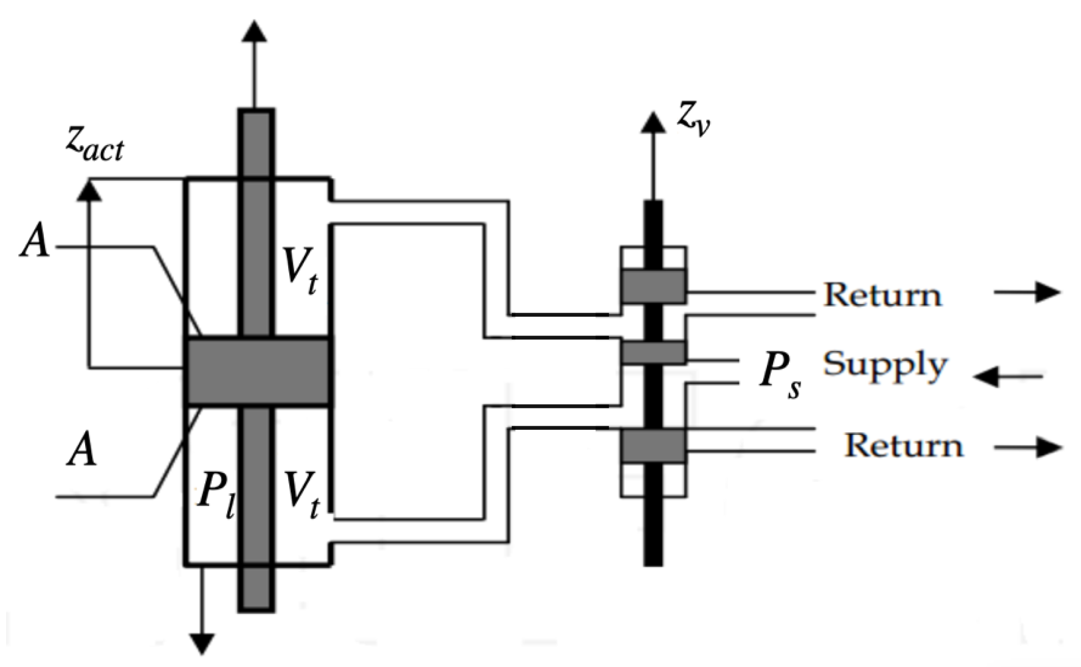
with k s i being the constant of the springs between the unsprung masses and the chassis, c s i being the damping coefficient of the dampers, k u i being the tire elastic constant of each tire. z c represents the vertical movement of the chassis mass at its center of gravity (COG), z s i represent the vertical displacement of the chassis mass at the point of connection with the suspension unit, l i is the distance between the COG of the chassis to the point of connection to each suspension unit, z u i is the vertical displacement of the suspension masses while z o i is the road disturbance in each of the modeled chassis corners i [ 1 , 2 ] . ϕ represents the pitch angle. Both control forces u f 1 and u f 2 are generated by an electro-hydraulic actuator with a servo spool valve. Figure 2 presents a schematic of the electro-hydraulic actuator.
This kind of actuator produces a force by redirecting the flow of pressure through the upper or lower chamber of the piston. Therefore, the force introduced to the suspension system is denoted as the following:
u f i = A P l i
The pressure dynamics are also modeled by the following differential equations
V t 4 β e P ˙ l i = Q i C t p P l i A ( z ˙ s i z ˙ u i )
With
Q i = s g n [ P s s g n ( z v i ) P l i ] C d w z v i 1 ρ | P s s g n ( z v i ) P l i |
i [ 1 , 2 ]
where V t is the total volume of the actuator, Q i is the load flow of each actuator, β e is the effective bulk modulus, C t p the piston leakage coefficient, w the spool valve gradient, C d the discharge coefficient, P s the pressure supply and ρ the hydraulic fluid density. It is assumed that both actuators are identical and independent. The displacement of each spool valve z v i is proportional to each control action u i ( k ) which are voltage signals. The spool valve behavior is defined by the following equation:
z ˙ v i = 1 τ ( z v i + k v u i ( k ) )
where k v is the valve gain and τ is a scaling factor.

3. LPV-SS Representation of the Half-Car Active Suspension Model with Fictional Input

In order to build a prediction model for the MPC paradigm, Equations (1)–(12) will be used to build a LPV-SS model with four different scheduling parameters and the use of a fictional input u f i c t . The proposed space state is of the following form, which is a traditional SS form, with matrices A and B being parameter dependent.
x ˙ ( t ) = A ρ 1 ( t ) , ρ 3 ( t ) , ρ 4 ( t ) x ( t ) + B ρ 2 ( t ) u ˜ ( t )
where x ˙ ( t ) = [ z c z ˙ c ϕ ϕ ˙ z u 1 z ˙ u 1 z u 2 z ˙ u 2 P l 1 z v 1 P l 2 z v 2 ] T and u ˜ ( t ) = [ u f i c t u 1 u 2 z o 1 z o 2 ] T .
The state matrices A and B are defined as the following:
A = 0 1 0 0 0 0 0 0 0 0 0 0 ( k s 1 + k s 2 m s ) ( c s 1 + c s 2 m s ) 0 ρ 1 ( c s 1 l 1 c s 2 l 2 m s ) k s 1 m s c s 1 m s k s 2 m s c s 2 m s A m s 0 A m s 0 0 0 0 1 0 0 0 0 0 0 0 0 ( l 1 k s 1 l 2 k s 2 I ϕ ) ( l 1 c s 1 l 2 c s 2 I ϕ ) 0 ρ 1 ( l 1 2 c s 1 + l 2 2 c s 2 I ϕ ) l 1 k s 1 I ϕ l 1 c s 1 I ϕ l 2 k s 2 I ϕ l 2 c s 2 I ϕ l 1 A I ϕ 0 l 2 A I ϕ 0 0 0 0 0 0 1 0 0 0 0 0 0 k s 1 m u 1 c s 1 m u 1 0 c s 1 l 1 ρ 1 m u 1 ( k s 1 + k u 1 m u 1 ) c s 1 m u 1 0 0 A m u 1 0 0 0 0 0 0 0 0 0 0 1 0 0 0 0 k s 2 m u 2 c s 2 m u 2 0 c s 2 l 2 ρ 1 m u 2 0 0 ( k s 2 + k u 2 m u 2 ) c s 2 m u 2 0 0 A m u 2 0 α A 0 0 0 α A 0 0 0 β γ ρ 3 0 0 0 0 0 0 0 0 0 0 0 1 τ 0 0 α A 0 0 0 0 0 α A 0 0 0 β γ ρ 4 0 0 0 0 0 0 0 0 0 0 0 1 τ
B = 0 0 0 0 0 ρ 2 ( k s 1 l 1 k s 2 l 2 m s ) 0 0 0 0 0 0 0 0 0 ρ 2 ( l 1 2 k s 1 + l 2 2 k s 2 I ϕ ) 0 0 0 0 0 0 0 0 0 k s 1 l 1 ρ 2 m u 1 0 0 k u 1 m u 1 0 0 0 0 0 0 k s 2 l 2 ρ 2 m u 2 0 0 0 k u 2 m u 2 α A l 1 ρ 2 0 0 0 0 0 k v i τ 0 0 0 α A l 2 ρ 2 0 0 0 0 0 0 k v i τ 0 0
where ρ 1 = cos ϕ , ρ 2 = sin ϕ , ρ 3 = s g n [ P s s g n ( z v 1 ) P l 1 ] | P s s g n ( z v 1 ) P l 1 , ρ 4 = s g n [ P s s g n ( z v 2 ) P l 2 ] | P s s g n ( z v 2 ) P l 2 , α = 4 β e V t , β = α C t p and γ = α C d ω 1 ρ . The inclusion of the scheduling variables allows the nonlinear differential equations presented in the half-car active suspension system to be expressed in a compact state-space form which allows the computation of the future values of the states in the MPC paradigm in a compact formulation. The fictional input u f i c t is set to a value of 1 at every sampling instant in order to insert non-state dependent values which are scheduling parameter dependent, while the disturbances z o 1 and z o 2 are considered as constants along the prediction horizon and measurable at every sampling instant k in order to predict the future states in the MPC strategy.
In Equations (13)–(15), the nonlinear half-car active suspension model with electro-hydraulic actuators can be represented by an LPV-SS model with matrices A and B being parameter-dependent matrices assumed to be linear at each sampling instant k. This allows the prediction of the future states to be performed in a compact matrix form, having the future states stored in a vector as is shown in the next section.

4. LPV-MPC Controller

In order to build an MPC with an LPV model, a prediction of the future states along the prediction horizon N p is formulated considering the variation of the parameter dependent matrices at every sampling step. The i-steps ahead prediction of the states of the half-car active suspension model is the following.
x ( k + i | k ) = j = 0 i 1 A d ρ i ( k + j ) x ( k ) + s = 1 i 1 l = s i 1 A d ρ i ( k + l ) B d ρ i ( k + s 1 ) u ˜ ( k + s 1 ) + B d ρ i ( k + i 1 ) u ˜ ( k + i 1 )
where A d ( ρ i ) and B d ( ρ i ) are the discretization of the continuous matrices A and B presented in Equations (14) and (15) by means of a zero-order hold (ZOH) as functions of the scheduling parameters ρ i . Prediction of the future states need to be done throughout the prediction horizon N p , thus Equation (16) can be expressed in a compact matrix equation of the following form.
X = Φ x ( k ) + Ψ U
where
X = x ( k + 1 | k ) x ( k + 2 | k ) : . x ( k + N p | k )
Φ ( k ) = A d ρ i ( k ) j = 0 1 A d ρ i ( k + j ) j = 0 N p 1 A d ρ i ( k + j )
Ψ ( k ) = B d ( ρ i ( k ) ) 0 n x · n u 0 n x · n u A d ( ρ i ( k + 1 ) ) B d ( ρ i ( k ) ) B d ( ρ i ( k + 1 ) ) 0 n x · n u A d ( ρ i ( k + 2 ) ) A d ( ρ i ( k + 1 ) ) B d ( ρ i ( k ) ) A d ( ρ i ( k + 2 ) ) B d ( ρ i ( k + 1 ) ) 0 n x · n u ( i = 1 N p 1 A d ( ρ i ( k + 1 ) ) ) B d ( ρ i ( k ) ) ( i = 1 N p 1 A d ( ρ i ( k + 2 ) ) ) B d ( ρ i ( k + 1 ) ) B d ( ρ i ( k + N p 1 ) )
U = u ˜ ( k ) u ˜ ( k + 1 ) : . u ˜ ( k + N p 1 )
where X R N p · n x , Φ R N p × n x · n x , Ψ R N p · n x × N p · n u and U R N p · n x , where n x represents the number of states in the half-car active suspension model and n u the number of inputs, including disturbances and fictional inputs. With the state prediction equation in matrix form, a cost function to minimize the deviation from the equilibrium of the states of the system and the energy consumption generated by the actuators can be defined as the following:
J = X T Q c X + U T R c U
where Q c and R c are weight matrix of appropriate dimensions. The objective of the MPC paradigm is to minimize (22) as a function of both inputs u 1 and u 2 along the prediction horizon N p subject to constraints in both inputs (23) and states (24).
u m i n u 1 ( k ) u 2 ( k ) u 1 ( k + 1 ) u 2 ( k + 1 ) u 1 ( k + N p ) u 2 ( k + N p ) u m a x
x m i n X x m a x
where u m i n and u m a x R N p × 2 and x m i n and x m a x R N p · n x . Then, classical MPC strategy is based on solving the optimization problem (22) at every sampling step. However, the cost function proposed in (22) is scheduling parameter dependent and while the value of the four scheduling parameters are considered measurable, its future values along the prediction horizon N p are unknown and must be estimated. To obtain an estimation of the four scheduling parameters ρ 1 , ρ 2 , ρ 3 and ρ 4 a recursive least squares (RLS) approach is used to estimate its future values based on its previous behavior and the system response for the previous inputs.

5. Scheduling Parameters Prediction Using RLS

To obtain an estimation of the four scheduling parameters along the prediction horizon, an RLS approach is used as presented by Sename, Morato and Normey-Rico in [37]. All of the four scheduling parameters are considered to be measurable at every sampling instant k and all the previous values of the scheduling parameters, the states, and the inputs of the system are stored and available. The future scheduling parameters will be estimated based on these previous measurements to consider the behavior of the system as well as the behavior of the parameter itself.
The behavior of each scheduling parameter can be approximated by a linear autoregressive with exogenous inputs (ARX) model, which is a function of the previous parameter values, the previous inputs to the system and the previous behavior of the states. This ARX model can be generally represented as:
ρ i ( k + N p ) = a 0 ρ i ( k ) + + a N p ρ i ( k N p ) + b 0 T u ( k 1 ) +
+ b N p T u ( k N p 1 ) + c 0 T x ˜ ( k ) + + c N p T x ˜ ( k N p )
where u = [ u 1 u 2 ] T are the controllable inputs and x ˜ are the selected states for each scheduling parameter in order to predict the behavior through the RLS algorithm as shown in Equation (33). Therefore, (25) can be expressed in a matrix form and be dependent only on known variables in order to be suitable for the MPC paradigm. To find a solution for the RLS algorithm, parameters a 0 to c N p need to be calculated. These parameters will be grouped in a vector as the following:
Θ ( k ) = [ a 0 a N p , b 0 T b N p T , c 0 T c N p T ] T
resulting in:
ρ i ( k ) = λ ( k ) T Θ ( k )
with:
λ ( k ) T = ρ i ( k N p ) , , ρ i ( k 2 N p ) , u T ( k N p 1 ) , u T ( k 2 N p 1 ) , x ˜ T ( k N p ) , , x ˜ T ( k 2 N p )
with (27) and (28) a direct solution for each scheduling parameter can be built and used to find ρ i in an online RLS algorithm as presented in [38]:
Θ ( k ) = Θ ( k 1 ) + σ ( k ) ρ i ( k ) λ ( k 1 ) T Θ ( k 1 )
Q ^ ( k ) = I σ ( k ) λ ( k ) T Q ^ ( k 1 ) μ
with μ [ 0 , 1 ] being a forgetting factor that gives exponentially less weight to older error samples of the RLS algorithm, I being the identity matrix, and σ ( k ) being a vector defined as:
σ ( k ) = 1 μ c ^ ( k ) Q ^ ( k 1 ) λ ( k )
and c ^ ( k ) is a scalar defined by:
c ^ ( k ) = 1 + γ ( k ) T Q ^ ( k 1 ) μ λ ( k )
In order to have a more accurate estimation of the scheduling parameters, Equation (25) will be adapted considering only the states that affect each scheduling parameter. Therefore, the state vector x ˜ will be defined depending on the scheduling parameter like the following.
x ˜ = [ x 1 , x 2 , , x 8 ] T ρ 1 , ρ 2 [ x 9 , x 10 ] T ρ 3 [ x 11 , x 12 ] T ρ 4
The proposed RLS algorithm for estimating the future values of the four scheduling parameters of the LPV model of the half-car active suspension is shown as Algorithm 1:
Algorithm 1 Recursive Least Squares Algorithm for scheduling parameter prediction
Offline
Step 1—Initialize Θ ( 0 ) and Q ^ ( 0 )
Online
Step 2—Obtain ρ i ( k ) , x ˜ ( k ) and u ( k )
Step 3—Construct λ T ( k ) vector
Step 4—Calculate scalar c ^
Step 5—Obtain vector σ ( k )
Step 6—Obtain Θ ( k )
Step 7—Obtain Q ^ ( k )
Step 8—Calculate ρ i ( k )
Step 9—Set k = k + 1 , If k > N p go to Step 10, else, go back to step 3
Step 10—Construct P ^ i ( k ) = ρ i ( k ) , ρ i ( k + 1 ) , , ρ i ( k + N p )
Algorithm 1 needs to be performed for every scheduling parameter ρ i . After solving the RLS for the N p future scheduling parameters every ρ i is considered known along the prediction horizon, and a vector containing every value of each scheduling parameter can be defined as: P ^ i ( k ) = ρ i ( k ) , , ρ i ( k + N p ) T . Therefore (17) is no longer an equation with unknown terms, and it can be solved through LMI optimization at every sampling instant k.

6. Quadratic Stability in the LPV-MPC Approach

With the estimation of the future scheduling parameters along the prediction horizon, the LPV-MPC strategy can be executed. To ensure quadratic stability of the LPV-MPC algorithm, the half-car active suspension model presented in (13) can be considered to be a parametric uncertain system with four different uncertain parameters being ρ 1 , ρ 2 , ρ 3 and ρ 4 . All four scheduling parameters will be considered to be variable and bounded around a certain range ρ i m i n ρ i ρ i m a x determined by the precision of the prediction of the RLS algorithm along the prediction horizon. This allows the MPC algorithm to have a solution space closer to the actual value of the scheduling parameter, rather than solving for every admissible value or possible value of the scheduling parameters, which results in a less restrictive optimization problem in terms of stability conditions when compared with the LPV approaches that consider that their scheduling parameters are not bounded or bounded by a rate of change. To ensure quadratic stability in a parametric uncertain system, the following linear matrix inequality (LMI) needs to be met as presented in [39].
A d ( ρ i ) + B d ( ρ i ) K T P A d ( ρ i ) + B d ( ρ i ) K P < 0
which is the Riccati Equation for parametric uncertain systems where P > 0 is a positive definite matrix of approapiate dimensions and K is a static feedback gain matrix. Afterwards, (34) can be pre- and post-multiplied by a matrix Q = P 1 and K Q = R to obtain:
Q A d T ( ρ i ) + R T B d T ( ρ i ) Q 1 A d ( ρ i ) Q + B d ( ρ i ) R Q < 0
To represent (35) as a compact LMI to cope with the MPC paradigm, the Schur complement can be applied to obtain the following compact LMI:
Q Q A d T ( ρ i ) + R B d ( ρ i ) A d ( ρ i ) Q + B d ( ρ i ) R Q > 0
the previous condition must be met for every point in the parameter space of the four scheduling parameters ρ i ϱ i with ϱ i being the allowable parameter space of each scheduling parameter. This led to an infinite number of LMI to be solved. Therefore, as the half-car active suspension model is considered to be a parametric uncertain system, the previous equation can be evaluated on the vertex of the scheduling parameter space to consider the worst-case scenarios only. Therefore, (36) can be rewritten as:
Q Q A d T ( ρ i , m ( j ) ) + R B d ( ρ i , m ( j ) ) A d T ( ρ i , m ( j ) ) Q + B d ( ρ i , m ( j ) ) R Q > 0
The previous condition must be met j [ k , k + N p ] and m [ 1 , 2 l ] , where 2 l is the total number of vertices on the parameter space ϱ and l is the number of scheduling variables ρ i . For the half-car active suspension model, the total number of vertices in the scheduling parameter space is equal to 16. Therefore, (37) is now a LMI finite problem which is equal to 16 · N p . Since there exist the consideration of a static feedback gain K , the control law is considered to be of the form u ( k ) = K x ( k ) . However, the LMI paradigm does not consider a static feedback gain matrix, therefore, the previous condition can be expressed as an inequality u ( k ) K x ( k ) . This led to a conservative performance of the MPC strategy due to the limitations of the input variable and the conservative nature of the quadratic stability condition in an uncertain system. To overcome this limitation, Section 7 aboard the inclusion of terminal sets in the LPV-MPC algorithm.
In order to include the quadratic stability conditions in the MPC algorithm, the following optimization problem needs to be solved in order to find the optimal control sequence at each time step k:
min U J s . t . ( 23 ) , ( 24 ) and ( 37 )

7. MPC-LQR for LPV Models

7.1. Attraction Sets and Terminal Set

The inclusion of LMI (37) to ensure stability may result in a conservative performance of the MPC algorithm, increasing settling times when the half-car active suspension system is facing up disturbances. To overcome the conservative performance present in the MPC paradigm due to the quadratic stability conditions, a series of attraction sets can be included in the MPC strategy. The use of attraction sets and terminal sets have been used widely in several MPC strategies, in [40] an offline MPC strategy for LPV systems using a trajectory based on nested ellipsoids is presented. The number of nested ellipsoids is dependent on the number of vertex of the polytope determined by the number of scheduling parameters to comply with robust stability conditions. However, in this approach, the corresponding feedback gain for every ellipsoid is computed offline and stored, and the selection of a matrix gain at every simulation step is determined through interpolation of the precomputed gains. In [41], an MPC for LPV systems using a path of ellipsoids to predict the possible behavior of the scheduling parameter along the prediction horizon N p is presented. The goal of this approach is to steer all the states to a terminal set, in which the states can be steered to the origin employing a stationary feedback gain rather than the control actions determined by the MPC law.
In this work, the future scheduling parameters are not known, but are predicted for the next N p steps using the RLS algorithm presented in Section 3; therefore, the ellipsoids to build around the scheduling parameters do not consider a bounded rate of change of each scheduling parameter but rather the prediction error measured by the RLS algorithm adjustments. To build an optimal desired trajectory, a path must be defined from every possible initial state x ( k ) to an attraction set located at k + N p steps.
To steer the system into the desired attraction set, a terminal cost term J T S is added to the cost function J presented in Equation (22). The terminal cost term is defined as the following
J T S = x ( k + N p ) ( x d s + x d i s t ) T L x ( k + N p ) ( x d s + x d i s t ) E ( P ^ )
where E ( P ^ ) = i = 1 4 j = k k + N p ρ i ( j ) λ ( j 1 ) T Θ ( j 1 ) 2 represents the sum of the squared errors of the four scheduling parameters in the RLS prediction for the future values along the prediction horizon. x ( k + N p ) are the predicted states at the end of the prediction horizon, x d s represents the desired state after N p steps obtained by a desired performance without any disturbance, x d i s t is the predicted effect of the disturbance on the states N p steps ahead and it was obtained by performing an open loop simulation of every possible disturbance from every initial set of states. Both x d s and x d i s t were computed offline and stored in a lookup table. L is a weighing matrix of appropriate dimensions ( n x × n x ) and should be selected depending on which states are more important to be steered to the attraction sets. For this application, the states involving the suspension differential equations are more weighted than the states involving the electro-hydraulic actuators, since the objective is to optimize the performance of the half-car suspension. Therefore, (22) is now defined as:
J = X T Q c X + U T R c U + J T S
The computation of every desired trajectory needs to be computed offline in order to decrease execution times for the MPC algorithm and only search for the closest set of states available in the lookup table.

7.2. MPC-LQR Dual Controller

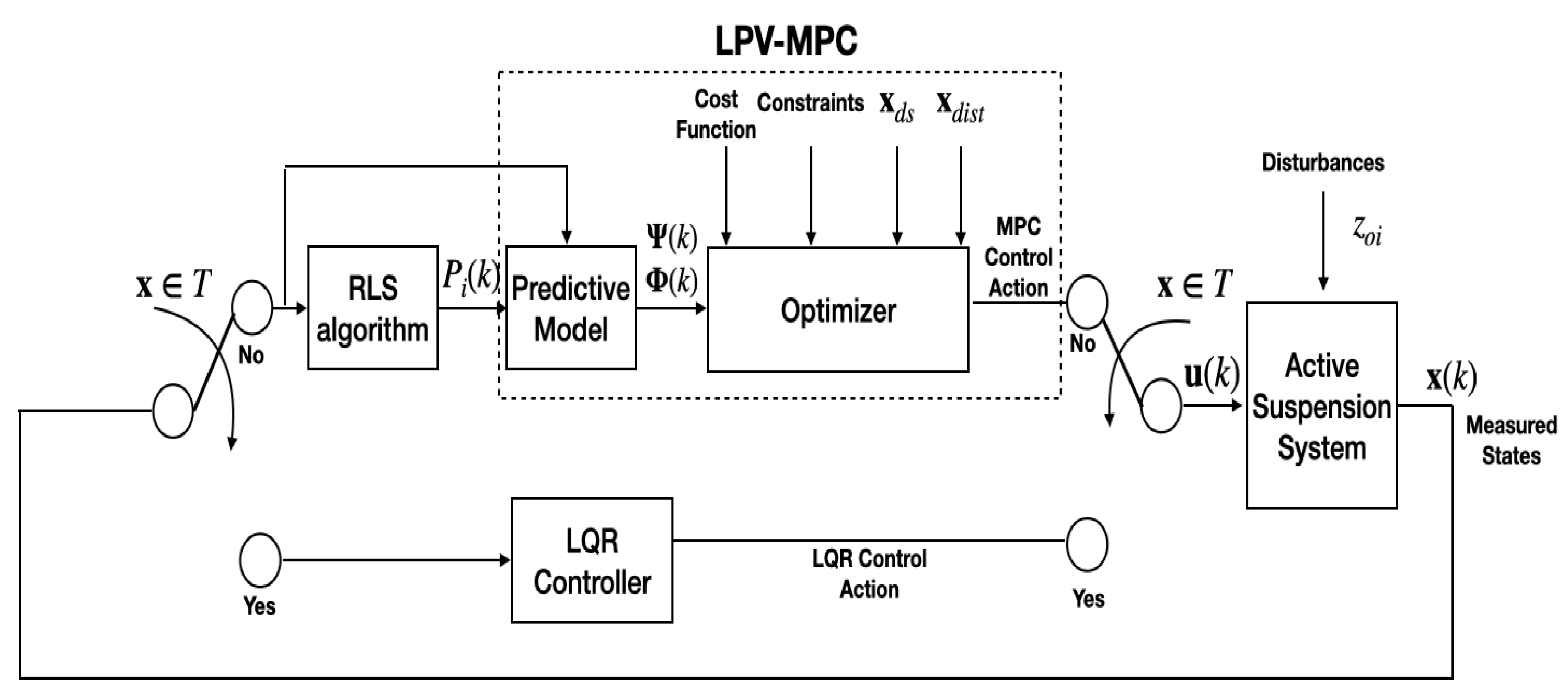
To reduce the computational burden of the MPC optimization problem, when the states of the system reach a terminal set close to the origin, the MPC algorithm no longer needs to be computed. Instead of the MPC law, an LPV-LQR gain can be computed based on the actual values of the scheduling parameter in order to cope with the small deviation of the states around the origin without the conservatism of the MPC algorithm with quadratic stability conditions and reducing the execution time of the optimization problem. The control law can now be presented as:
u ( k ) = U mpc x ( k ) T K LQR ( ρ i ) x ( k ) x ( k ) T
where K LQR ( ρ i ) is the LQR gain dependent on the scheduling parameters ρ i i [ 1 , 4 ] and T is the terminal invariant set defined around the equilibrium point of the system.
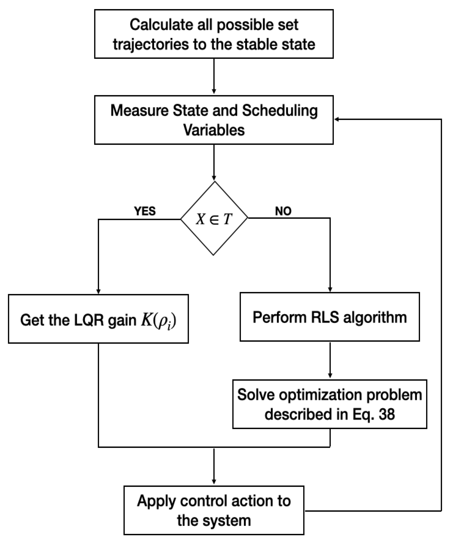
Figure 3 presents the block diagram for the proposed LPV-MPC-LQR control strategy for the half-car active suspension system. Additionally, the LPV-MPC-LQR algorithm is shown in the flowchart presented in Figure 4.

8. Results and Discussion

To prove the efficiency of the proposed MPC-LQR-LPV control strategy described in Section 7 the following simulation of the half-car active suspension system against a typical road disturbance is presented. The control algorithm was tested using a Simulink model of the active suspension system presented in Section 2. Table 1 shows the specifications of the half-car active suspension system as presented in [14].
In order to comply with the MPC paradigm, a discretization is made using a sampling time T s = 10 ms. A prediction horizon of N p = 3 was determined after several tests using different prediction horizons. Using prediction horizons longer than 3 require longer optimization time and resulted in more inaccurate prediction of the scheduling variables while the overall performance of the algorithm was not improved significantly. The control objective is to maintain passenger comfort by minimizing the acceleration of the chassis mass m s and the chassis pitch ϕ while maintaining safe driving conditions by means of minimizing the stroke z s i z u i of both front and rear suspension units. The following constraints were included in the control inputs and the states.
12 V u 1 ( k ) 12 V
12 V u 2 ( k ) 12 V
1 cm z v 1 1 cm
1 cm z v 2 1 cm
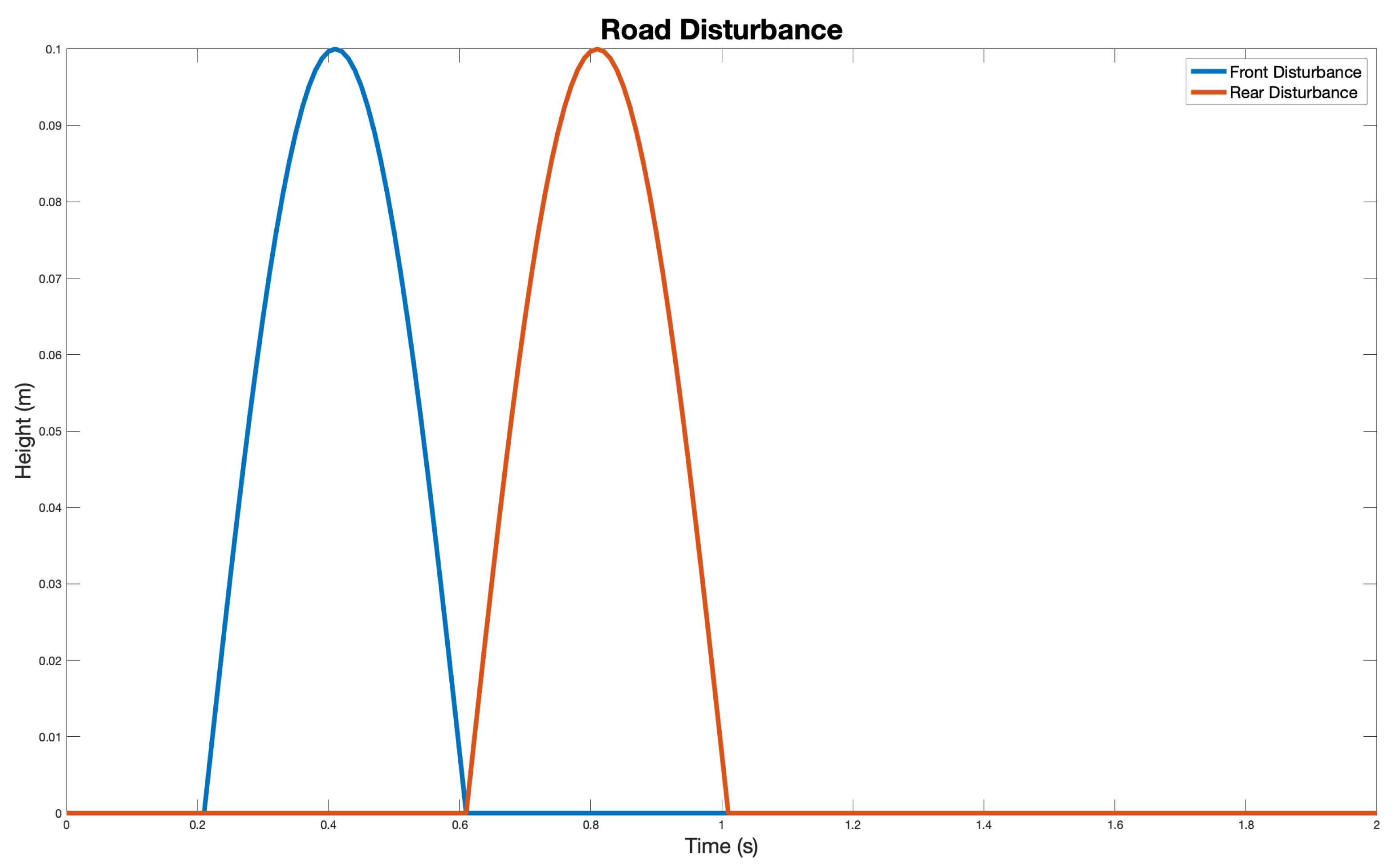
To test the efficiency of the proposed control strategy, the half-car active suspension system is disturbed by a 10 cm bump with a length of 5 m while the car is driving at a velocity of 45 km/h. Figure 5 shows the road profile of the disturbance for both wheels of the half-car vehicle.
Figure 6, Figure 7, Figure 8 and Figure 9 show the behavior of the suspension when the disturbance showed in Figure 5 is introduced. The control algorithm and the system simulations were done in the Matlab-Simulink software environment. Furthermore, the software YALMIP [42] using the QP-solver SDPT3 was used to solve the MPC optimization problem. The results presented in [14] are included to make a comparison. Additionally, the results using the pure LQR controller and the pure MPC controller are included to prove the efficiency of the combined control strategies.
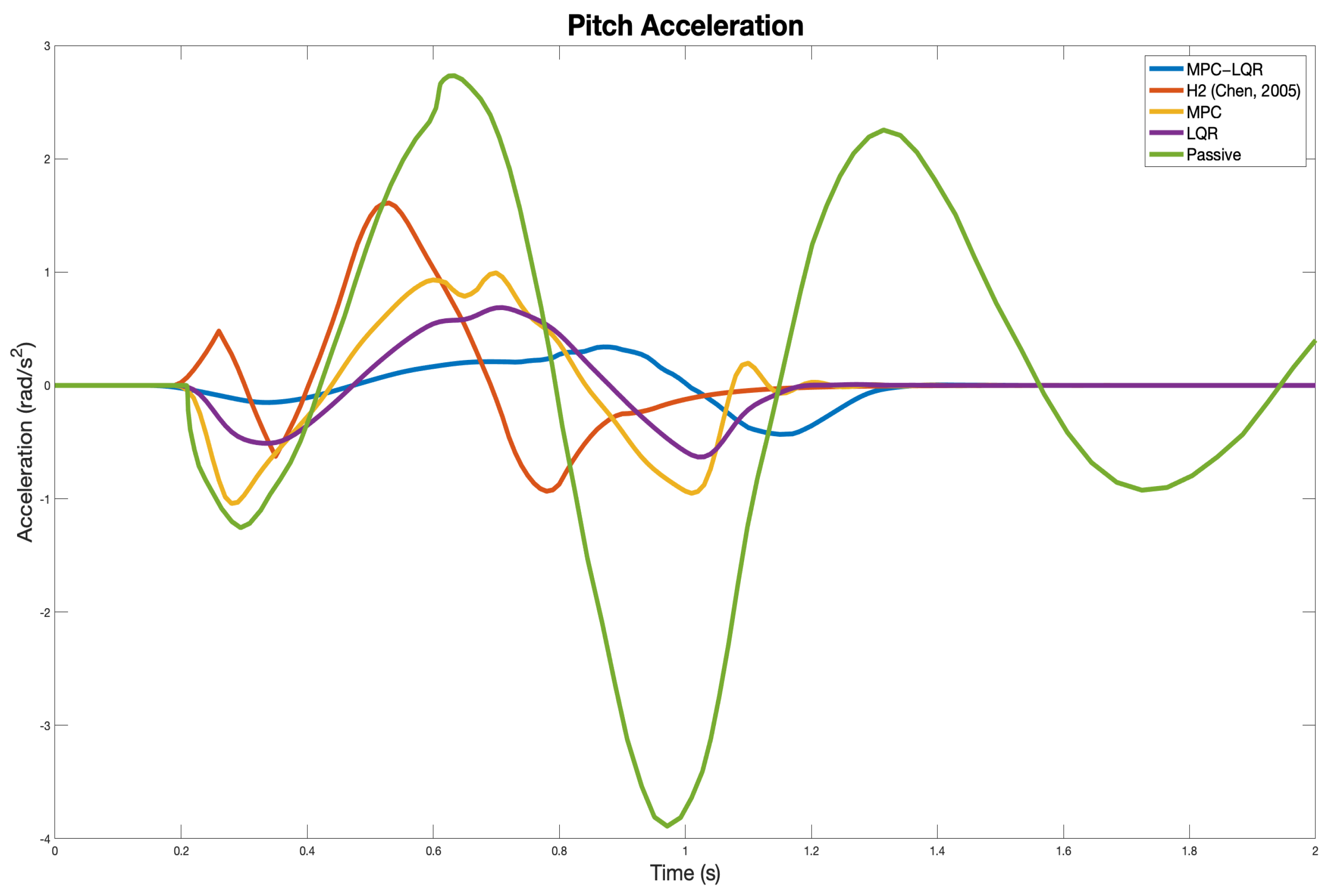
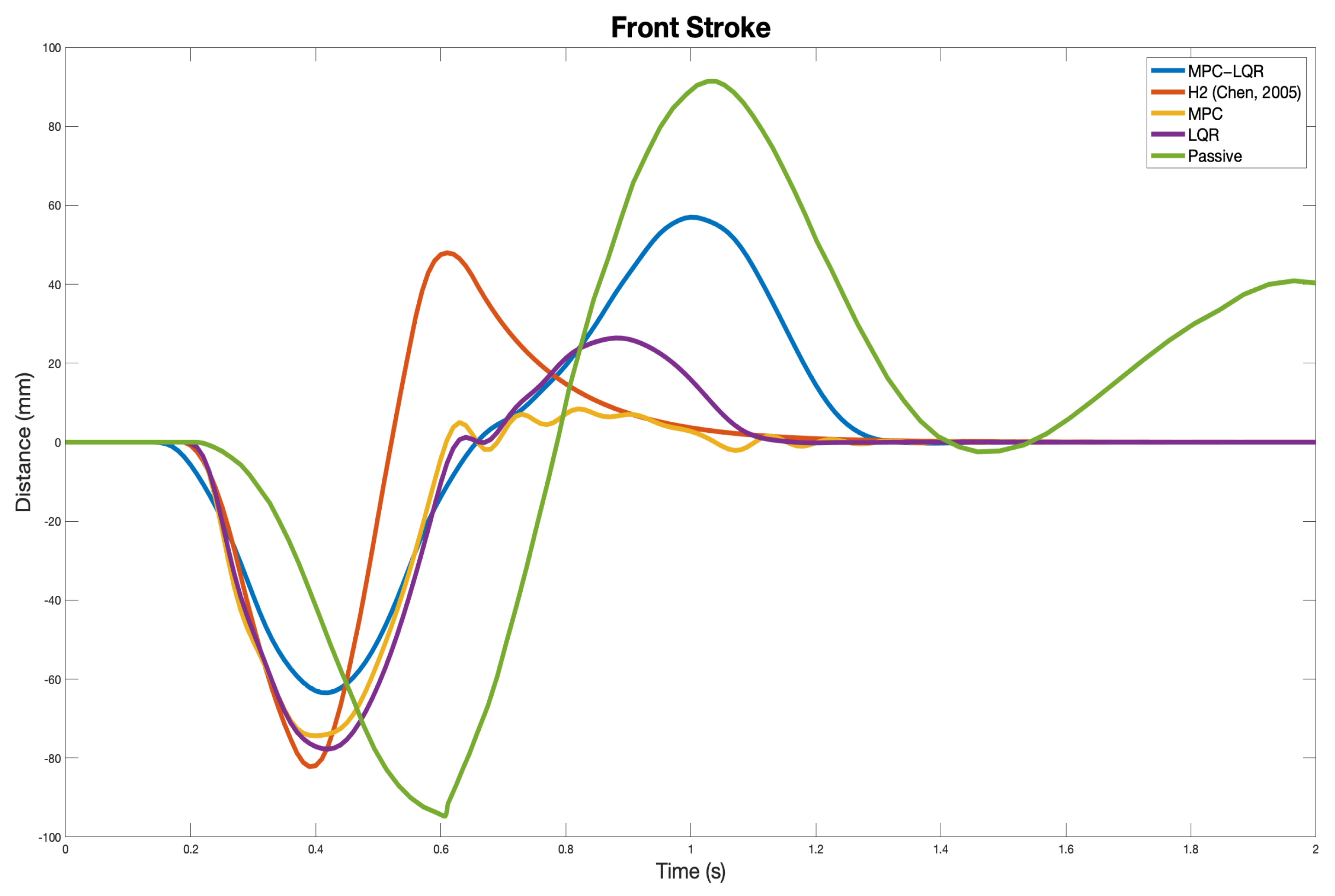
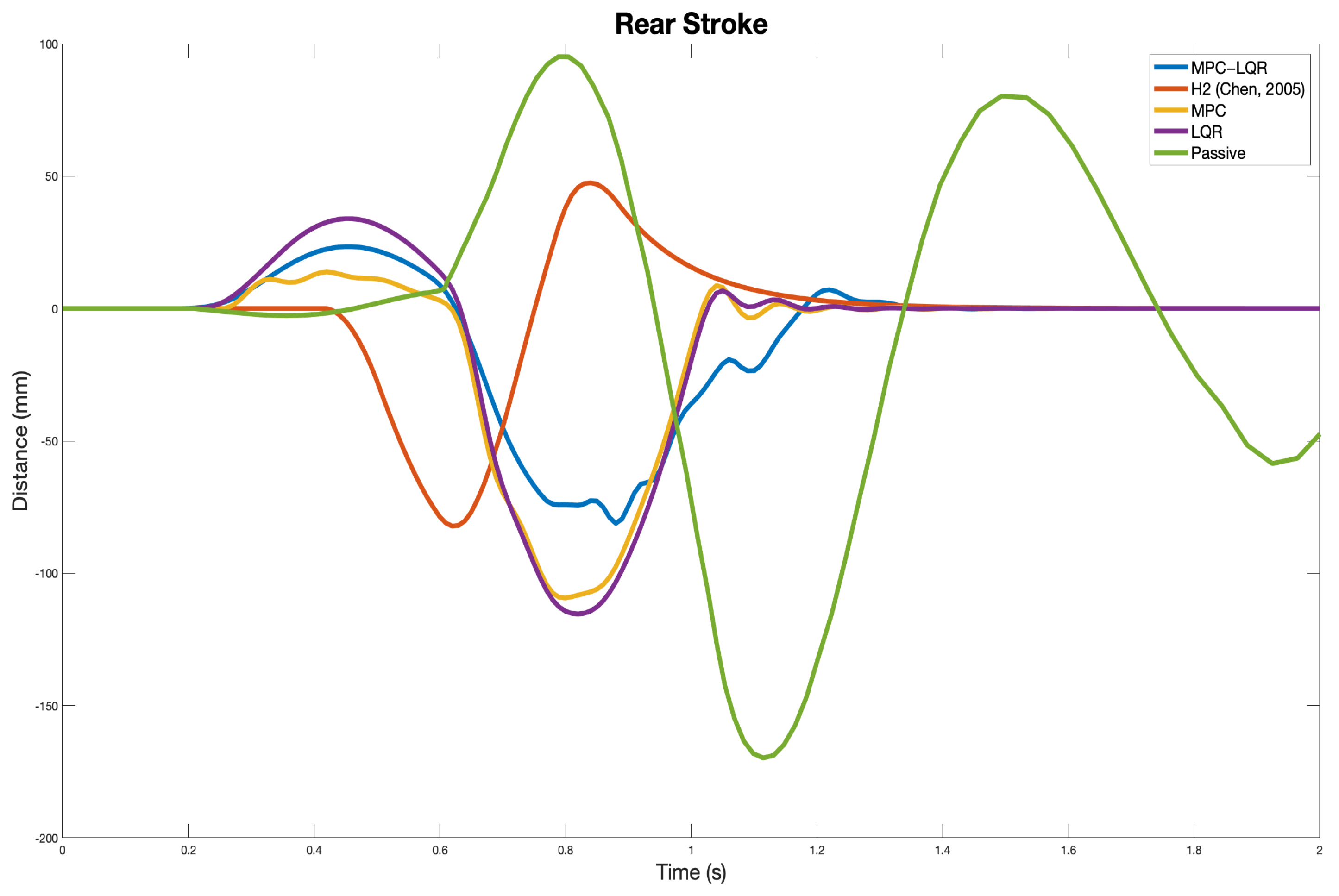
The results of the accelerations of both the chassis and the pitch angle show a better performance, reducing the peak values of both the passive suspension and the H2 controller. The settling time increases in the proposed LPV-MPC-LQR approach in order to dissipate the disturbance energy in the suspension unit while preserving comfort for the passengers. In terms of road-holding, the suspension strokes also exhibit a reduction in their peak values while maintaining the same settling time, resulting in better road-holding for both the front and rear suspension unit when compared to the other controllers presented and the passive suspension.
Additionally to the presented graphic results, Table 2 and Table 3 present the numerical results of the compared algorithms. Table 2 presents the RMS value of the chassis acceleration, pitch acceleration, and front and rear stroke, while Table 3 presents the peak values for the aforementioned variables.
As shown in the previous Tables, the proposed MPC-LQR-LPV strategy presents better results in terms of comfort than the other control strategies, reducing its RMS values in a 72% and 54% in chasis and pitch acceleration, respectively, while the attenuation in the peak values shows an improvement of 71% for chassis acceleration and 64% for pitch acceleration when compared with the H2 controller. Furthermore, road-holding is preserved in both front and rear suspension units with fewer peak values for the stroke c[pink] with a reduction of 23% in the front stroke peak value when compared to the H2 controller strategy while maintaining similar RMS values for both rear and front strokes.

9. Conclusions and Future Work

In this paper, the control of a half-car active suspension system with electro-hydraulic actuators is made by an MPC-LQR LPV control strategy ensuring Quadratic Stability and the inclusion of attraction sets. The proposed strategy runs an RLS algorithm to obtain the prediction of the four scheduling parameters of the LPV system along a prediction horizon to simplify the optimization problem of the MPC. This application can cope with other nonlinear systems with multiple nonlinearities which can be embedded into LPV representations and therefore reduce the complexity of the MPC optimization problem and allow faster execution times. The results show improvements in the performance of the half-car active suspension system with electro-hydraulic actuators in terms of passengers’ comfort while maintaining appropriate road-holding conditions. Future research works will focus on recursive feasibility analysis based on both stability and robust conditions. Optimization of the MPC-LQR LPV algorithm to achieve faster execution times using embedded systems techniques will be considered as future work as well.

Author Contributions

All Authors D.R.-G., A.F.-C., F.B.-C., D.S. and C.S. have contributed as follows: Conceptualization, D.R.-G., A.F.-C., F.B.-C., D.S. and C.S.; Methodology, D.R.-G., A.F.-C., F.B.-C., D.S. and C.S.; Software, D.R.-G., D.S. and C.S.; Validation, D.R.-G., A.F.-C., F.B.-C., D.S. and C.S.; Formal analysis, D.R.-G., A.F.-C., F.B.-C., D.S. and C.S.; Investigation, D.R.-G., A.F.-C., F.B.-C., D.S. and C.S.; Writing—original draft preparation, D.R.-G. and A.F.-C.; Writing—review and editing, D.R.-G., A.F.-C., F.B.-C., D.S. and C.S.; supervision, A.F.-C. and F.B.-C.; project administration A.F.-C. All authors have read and agreed to the published version of the manuscript.

Funding

This research received no external funding.

Institutional Review Board Statement

Not applicable.

Informed Consent Statement

Not applicable.

Data Availability Statement

No new data were created or analyzed in this study. Data sharing is not applicable to this article.

Acknowledgments

The authors would like to thank Consejo Nacional de Ciencia y Tecnología (CONACyT) and Tecnológico de Monterrey for the financial support to conduct the present research. Additionally, thanks go to the Nano-sensors and Devices Research Group and the Robotics Research Group from the School of Engineering and Sciences of Tecnológico de Monterrey for the support given to develop this work.

Conflicts of Interest

The authors declare no conflict of interest.

References

  1. Sam, Y.M.; Hudha, K. Modelling and Force Tracking Control of Hydraulic Actuator for an Active Suspension System. In Proceedings of the 1ST IEEE Conference on Industrial Electronics and Applications (2006), Singapore, 24–26 May 2006; pp. 1–6. [Google Scholar] [CrossRef] [Green Version]
  2. Su, X. Master–slave control for active suspension systems with hydraulic actuator dynamics. IEEE Access 2017, 5, 3612–3621. [Google Scholar] [CrossRef]
  3. Xiao, L.; Zhu, Y. Sliding-mode output feedback control for active suspension with nonlinear actuator dynamics. J. Vib. Control 2015, 21, 2721–2738. [Google Scholar] [CrossRef]
  4. Al Aela, A.M.; Kenne, J.-P.; Angue Mintsa, H. A Novel Adaptive and Nonlinear Electrohydraulic Active Suspension Control System with Zero Dynamic Tire Liftoff. Machines 2020, 8, 38. [Google Scholar] [CrossRef]
  5. Bello, M.M.; Babawuro, A.Y.; Fatai, S. Active suspension force control with electro-hydraulic actuator dynamics. ARPN J. Eng. Appl. Sci. 2015, 10, 17327–17331. [Google Scholar]
  6. Senthil Kumar, P.; Sivakumar, K.; Kanagarajan, R.; Kuberan, S. Adaptive Neuro Fuzzy Inference System control of active suspension system with actuator dynamics. J. Vibroeng. 2018, 20, 541–549. [Google Scholar] [CrossRef] [Green Version]
  7. Sam, Y.M.; Suaib, N.M.; Osman, J.H.S. Proportional integral sliding mode control for the half-car active suspension system with hydraulic actuator. In Proceedings of the WSEAS International Conference. In Proceedings of the Mathematics and Computers in Science and Engineering, World Scientific and Engineering Academy and Society, Hangzhou, China, 6–8 April 2018. [Google Scholar]
  8. Aldair, A.A.; Wang, W.J. Neural controller based full vehicle nonlinear active suspension systems with hydraulic actuators. Int. J. Control Autom. 2011, 4, 79–94. [Google Scholar]
  9. Aldair, A.A.; Wang, W. FPGA based adaptive neuro fuzzy inference controller for full vehicle nonlinear active suspension systems. Int. J. Artif. Intell. Appl. 2010, 1, 1–15. [Google Scholar] [CrossRef] [Green Version]
  10. Aldair, A.A.; Wang, W.J. Design of fractional order controller based on evolutionary algorithm for a full vehicle nonlinear active suspension systems. Int. J. Control Autom. 2010, 3, 33–46. [Google Scholar]
  11. Talib, M.H.A.; Darns, I.Z.M. Self-tuning PID controller for active suspension system with hydraulic actuator. In Proceedings of the 2013 IEEE Symposium on Computers & Informatics (ISCI), Langkawi, Malaysia, 7–9 April 2013; pp. 86–91. [Google Scholar] [CrossRef]
  12. Ahmed, A.E.N.S.; Ali, A.S.; Ghazaly, N.M.; Abdel-Jaber, G.T. PID controller of active suspension system for a quarter car model. Int. J. Adv. Eng. Technol. 2015, 8, 899–909. [Google Scholar]
  13. Emam, A.S. Fuzzy Self Tuning of PID controller for active suspension system. Adv. Powertrains Automot. 2015, 1, 34–41. [Google Scholar] [CrossRef]
  14. Chen, H.; Liu, Z.Y.; Sun, P.Y. Application of constrained H control to active suspension systems on Half-Car models. J. Dyn. Syst. Meas. Control 2005, 127, 345–354. [Google Scholar] [CrossRef]
  15. Wang, R.; Jing, H.; Karimi, H.R.; Chen, N. Robust fault-tolerant H control of active suspension systems with finite-frequency constraint. Mech. Syst. Signal Process. 2015, 62, 341–355. [Google Scholar] [CrossRef]
  16. Xu, F.X.; Liu, X.H.; Chen, W.; Zhou, C.; Cao, B.W. Improving handling stability performance of four-wheel steering vehicle based on the H2/H robust control. Appl. Sci. 2019, 9, 857. [Google Scholar] [CrossRef] [Green Version]
  17. Riofrio, A.; Sanz, S.; Boada, M.J.L.; Boada, B.L. A LQR-based controller with estimation of road bank for improving vehicle lateral and rollover stability via active suspension. Sensors 2017, 17, 2318. [Google Scholar] [CrossRef] [PubMed] [Green Version]
  18. Yao, Y. Optimization design of active suspension of vehicle based on LQR control. J. Phys.: Conf. Ser. 2020, 1629, 012094. [Google Scholar] [CrossRef]
  19. Khan, M.A.; Abid, M.; Ahmed, N.; Wadood, A.; Park, H. Nonlinear Control Design of a Half-Car Model Using Feedback Linearization and an LQR Controller. Appl. Sci. 2020, 10, 3075. [Google Scholar] [CrossRef]
  20. Samadi, F.; Moghadam-Fard, H. Active suspension system control using adaptive neuro fuzzy (anfis) controller. Int. J. Eng. 2015, 28, 396–401. [Google Scholar]
  21. Zare, K.; Mardani, M.M.; Vafam, N.; Khooban, M.H.; Sadr, S.S.; Dragičević, T. Fuzzy-logic-based adaptive proportional-integral sliding mode control for active suspension vehicle systems: Kalman filtering approach. Inf. Technol. Control 2019, 48, 648–659. [Google Scholar] [CrossRef]
  22. Zhang, J.; Yang, Y.; Hu, M.; Fu, C.; Zhai, J. Model Predictive Control of Active Suspension for an Electric Vehicle Considering Influence of Braking Intensity. Appl. Sci. 2021, 11, 52. [Google Scholar] [CrossRef]
  23. Göhrle, C.; Schindler, A.; Wagner, A.; Sawodny, O. Model predictive control of semi-active and active suspension systems with available road preview. In Proceedings of the 2013 European Control Conference (ECC), Zurich, Switzerland, 17–19 July 2013; pp. 1499–1504. [Google Scholar] [CrossRef]
  24. Theunissen, J.; Sorniotti, A.; Gruber, P.; Fallah, S.; Ricco, M.; Kvasnica, M.; Dhaens, M. Regionless explicit model predictive control of active suspension systems with preview. IEEE Trans. Ind. Electron. 2020, 67, 4877–4888. [Google Scholar] [CrossRef]
  25. Yao, J.; Wang, M.; Li, Z.; Jia, Y. Research on model predictive control for automobile active tilt based on active suspension. Energies 2021, 14, 671. [Google Scholar] [CrossRef]
  26. Enders, E.; Burkhard, G.; Munzinger, N. Analysis of the Influence of Suspension Actuator Limitations on Ride Comfort in Passenger Cars Using Model Predictive Control. Actuators 2020, 9, 77. [Google Scholar] [CrossRef]
  27. Wang, D.; Zhao, D.; Gong, M.; Yang, B. Research on robust model predictive control for electro-hydraulic servo active suspension systems. IEEE Access 2017, 6, 3231–3240. [Google Scholar] [CrossRef]
  28. Rodriguez-Guevara, D.; Favela-Contreras, A.; Beltran-Carbajal, F.; Sotelo, D.; Sotelo, C. Active Suspension Control Using an MPC-LQR-LPV Controller with Attraction Sets and Quadratic Stability Conditions. Mathematics 2021, 9, 2533. [Google Scholar] [CrossRef]
  29. Haemers, M.; Derammelaere, S.; Ionescu, C.M.; Stockman, K.; De Viaene, J.; Verbelen, F. Proportional-integral state-feedback controller optimization for a full-car active suspension setup using a genetic algorithm. IFAC-PapersOnLine 2018, 51, 1–6. [Google Scholar] [CrossRef]
  30. Gustafsson, A.; Sjögren, A. Neural Network Controller for Semi-Active Suspension Systems with Road Preview. Master’s Thesis, Charmers University of Technology, Gothenburg, Sweden, 2019. [Google Scholar]
  31. Ayub, A.; Sabir, Z.; Shah, S.Z.H.; Wahab, H.A.; Sadat, R.; Ali, M.R. Effects of homogeneous-heterogeneous and Lorentz forces on 3-D radiative magnetized cross nanofluid using two rotating disks. Int. Commun. Heat Mass Transf. 2022, 130, 105778. [Google Scholar] [CrossRef]
  32. Sadat, R.; Agarwal, P.; Saleh, R.; Ali, M.R. Lie symmetry analysis and invariant solutions of 3D Euler equations for axisymmetric, incompressible, and inviscid flow in the cylindrical coordinates. Adv. Differ. Equ. 2021, 486. [Google Scholar] [CrossRef]
  33. Ali, M.R.; Ma, W.X.; Sadat, R. Lie symmetry analysis and invariant solutions for (2 + 1) dimensional Bogoyavlensky-Konopelchenko equation with variable-coefficient in wave propagation. J. Ocean. Eng. Sci. 2021. [Google Scholar] [CrossRef]
  34. Sabir, Z.; Ali, M.R.; Raja, M.A.Z.; Shoaib, M.; Artidoro, R.; Nunez, S.; Sadat, R. Computational intelligence approach using Levenberg—Marquardt backpropagation neural networks to solve the fourth-order nonlinear system of Emden–Fowler model. Eng. Comput. 2021. [Google Scholar] [CrossRef]
  35. Boyd, S.; Balakrishnan, V.; Feron, E.; ElGhaoui, L. Control system analysis and synthesis via linear matrix inequalities. In Proceedings of the American Control Conference, San Francisco, CA, USA, 2–4 June 1993; pp. 2147–2154. [Google Scholar] [CrossRef] [Green Version]
  36. Szaszi, I.; Gáspár, P.; Bokor, J. Nonlinear active suspension modelling using linear parameter varying approach. In Proceedings of the 10th Mediterranean Conference on Control and Automation, Lisbon, Portugal, 9–12 July 2002; pp. 1–10. [Google Scholar]
  37. Morato, M.M.; Normey-Rico, J.E.; Sename, O. Novel qLPV MPC design with least-squares scheduling prediction. IFAC-PapersOnLine 2019, 52, 158–163. [Google Scholar] [CrossRef]
  38. Franklin, G.F.; Powell, J.D.; Workman, M.L. Digital Control of Dynamic Systems; Addison-Wesley: Reading, MA, USA, 1988; Volume 3. [Google Scholar]
  39. Boyd, S.; El Ghaoui, L.; Feron, E.; Balakrishnan, V. Linear Matrix Inequalities in System and Control Theory; Society for Industrial and Applied Mathematics: Philadelphia, PA, USA, 1994; Chapter 5; pp. 61–76. [Google Scholar]
  40. Bumroongsri, P.; Kheawhom, S. An ellipsoidal off-line model predictive control strategy for linear parameter varying systems with applications in chemical processes. Syst. Control Lett. 2012, 61, 435–442. [Google Scholar] [CrossRef]
  41. Suzukia, H.; Sugie, T. MPC for LPV systems with bounded parameter variation using ellipsoidal set prediction. In Proceedings of the 2006 American Control Conference, Minneapolis, MN, USA, 14–16 June 2006; p. 6. [Google Scholar] [CrossRef]
  42. Lofberg, J. Automatic robust convex programming. Optim. Methods Softw. 2012, 27, 115–129. [Google Scholar] [CrossRef] [Green Version]
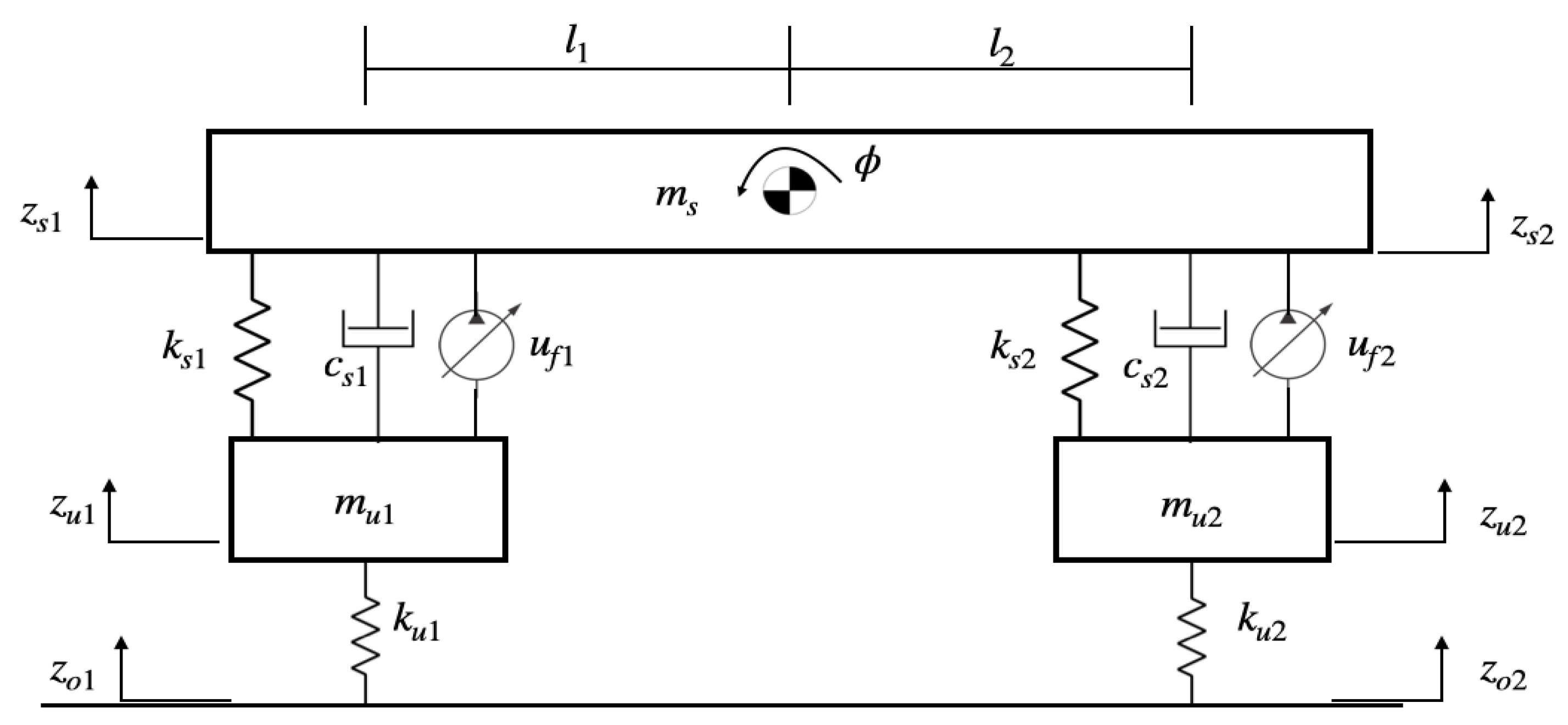
Figure 1. Half-Car Active Suspension System.
Machines 10 00137 g001
Figure 2. Electro-Hydraulic Actuator with Servo Spool Valve.
Machines 10 00137 g002
Figure 3. Block diagram of the proposed LPV-MPC-LQR control strategy for the Half-Car Active Suspension system.
Machines 10 00137 g003
Figure 4. Flow diagram of the LPV-MPC-LQR control strategy.
Machines 10 00137 g004
Figure 5. Road disturbance effect in both wheels of the half-car active suspension system.
Machines 10 00137 g005
Figure 6. Chassis acceleration (Blue—MPC-LQR, Red—H2, Yellow—MPC, Purple—LQR, Green—Passive).
Machines 10 00137 g006
Figure 7. Pitch Acceleration (Blue—MPC-LQR, Red—H2, Yellow—MPC, Purple—LQR, Green—Passive).
Machines 10 00137 g007
Figure 8. Front Stroke (Blue—MPC-LQR, Red—H2, Yellow—MPC, Purple—LQR, Green—Passive).
Machines 10 00137 g008
Figure 9. Rear Stroke (Blue—MPC-LQR, Red—H2, Yellow—MPC, Purple—LQR, Green—Passive).
Machines 10 00137 g009
Table 1. Constant Values of the Active Suspension system.
VariableValueUnits
m s 690kg
m u 1 40kg
m u 2 45kg
I ϕ 1222kg m 2
k s 1 18,000N/m
k s 2 22,000N/m
k u 1 200,000N/m
k u 2 200,000N/m
c s 1 1000N/(m/s)
c s 2 1000N/(m/s)
l 1 1.3m
l 2 1.5m
P s 10,342,500Pa
τ 1/30s
A 3.35 × 10 4 m 2
β 1s 1
α 4.515 × 10 13 N/m 5
γ 1.545 × 10 9 N/m 5 / 2 /kg 1 / 2
k v 1 × 10 4 m/V
Table 2. RMS Values performance.
VariableMPC-LQR-LPVH2(Chen, 2005)MPCLQRPassive
Chassis Acceleration (m/s 2 )0.15800.57160.16770.26710.7498
Pitch Acceleration (rad/s 2 )0.18370.39660.43490.29100.5886
Front Stroke (m)0.02760.01080.02380.02610.0537
Rear Stroke (m)0.02890.01020.03500.03790.0665
Table 3. Max Values performance.
VariableMPC-LQR-LPVH2(Chen, 2005)MPCLQRPassive
Chassis Acceleration (m/s 2 )0.47661.64020.54870.71723.5120
Pitch Acceleration (rad/s 2 )0.57791.61011.04160.68693.8897
Front Stroke (m)0.06350.08220.07440.07770.0947
Rear Stroke (m)0.08140.08220.10940.11540.1698
Publisher’s Note: MDPI stays neutral with regard to jurisdictional claims in published maps and institutional affiliations.