Article

Investigation into the Electrohydraulic Synchronous Motion Control of a Thrust System for a Tunnel Boring Machine

1
State Key Laboratory of Fluid Power & Mechatronic Systems, Zhejiang University, Hangzhou 310027, China
2
Department of Mechanical Engineering, Shantou University, Shantou 515063, China
*
Author to whom correspondence should be addressed.
Machines 2022, 10(2), 119; https://doi.org/10.3390/machines10020119
Submission received: 5 January 2022 / Revised: 4 February 2022 / Accepted: 7 February 2022 / Published: 8 February 2022
(This article belongs to the Special Issue Advanced Control of Industrial Electro-Hydraulic Systems)

Abstract

:
The thrust system of a tunnel boring machine plays a crucial role by driving the machine ahead and supporting the gripper shoes stably. A thrust hydraulic control system, assembled with a proportional flow control valve and a pressure relief valve, is established with system operating parameters. The mathematical model of a thrust electrohydraulic system is presented. To improve the control characteristics of the thrust system, a self-tuning fuzzy PID controller was introduced in synchronization motion control situations. To attain the best control parameters, three synchronization motion control systems were used to control the thrust propel cylinders. Tests on a Ø2.5 m scaled TBM test rig were carried out to verify the capabilities of the ISCS, SRSCS and CRSCS. Comparative tests were conducted, and the results showed that the thrust system adopting SRSCS achieved the least oscillation and the quickest response. The steady-state displacement error decreased by about 33.3% in contrast to the ISCS and CRSCS.

1. Introduction

A tunnel boring machine (TBM) is a rock crushing machine with continuous slagging and supporting integrated [1,2,3]. Compared to traditional drilling and blasting methods, TBMs have been used in long-distance and high-stress rock tunnels with a high safety and efficiency [4,5,6,7,8,9]. TBMs were developed from shield tunneling technology. Modern shield machines are integrated with mechanical, electrical, hydraulic, sensing and information technology, containing functions for cutting soil, transporting soil ballast, assembled tunnel lining, measuring, orientation and rectification [10,11,12]. More and more tunnels are employed to accommodate the construction of transportation systems, electricity and communication nowadays, which leads to an extensive application of TBMs in subway, railway, highway, municipal and hydroelectric tunnel projects [5,8,13,14].
A typical mainframe mechanical structure of a hard rock TBM consists of a cutterhead system, a support system, propel cylinders and gripper shoes, as shown in Figure 1. The thrust system not only drives the machine ahead and supports the gripper shoes stably while tunneling, but also rectifies the attitude of the TBM to march along the expected path. The actuators of a TBM are hydraulic cylinders due to their high power/mass ratio, fast response and high stiffness [15,16,17]. At present, the thrust control relies majorly on TBM drivers in the monitor room of the machine. High-accuracy thrust control methods of electrohydraulic systems are essential to improve the engineering efficiency ulteriorly.
The automation control of tunnel engineering projects had been carried out in many studies. Jacob et al. [5] explored a probabilistic geostatistics-based approach to cutter tool wear and cutterhead clogging prediction, which provided a significantly more accurate prediction of the necessary mitigation measures than the conventional deterministic approach, with estimated cost savings including a 40–42% reduction in estimated tool replacements and a 17% reduction in estimated conditioning volume. Lyu et al. [18,19] developed a novel pump-and-valve-combined electrohydraulic system to achieve both objectives of high precision-tracking performance and high energy efficiency. The results indicated that the proposed system realized the same high level of tracking precision as the valve control method but consumed about 35–47% less energy. Hou et al. [20] designed a new propulsion system for a shield tunneling machine based on compliance characteristics. A new shield thrust system was designed by means of a compliance characteristics comparison. Results showed that the compliance index of the new shield thrust system increased by 25% compared to that of the existing one. Wang et al. [21] proposed a prediction method and its corresponding model of penetration rate based on a mechanical analysis. A basic form of the penetration rate prediction equation suitable for different projects was also proposed using the single variable control method. The calculation equation was verified with a correlation coefficient of 0.78 and a mean absolute percentage error of 10.9%. Liu et al. [22] studied the most important parameters of the rock mass and machine, and increased the average penetration rate of the TBM by 11.10% and the average cutter life by 15.62% by introducing an intelligent decision method for the main control parameters of the TBM based on the multiobjective optimization of excavation efficiency and cost.
There are four propel cylinders in the thrust system of a TBM. The synchronization accuracy is an important factor for the tunneling success. Many studies have been published on the synchronization control in a hydraulic system. Zhang et al. [23] presented an equivalent synchronous control strategy based on fuzzy PID control. The results showed that the method can maintain the synchronous accuracy of the double hydraulic cylinders between 0 and 0.66 mm under the condition of satisfying the working requirements of the scissor lift mechanism. Wang et al. [24] proposed an integrated control strategy for the position synchronization control of dual electrohydraulic actuators with unknown dead zones. Li et al. [25] proposed a design scheme for the mechanical structure of the synchronous precision control of a double-cylinder gantry hydraulic machine. By adopting a simple hydraulic circuit, the flexible connection of the piston rod of the oil cylinder and the beam was used to reduce the damage caused by the deflection of the beam of the hydraulic system and the machinery of the hydraulic machine. By aligning the cylinder rod and the taper hole of the beam, the position of the beam was corrected to ensure the machining precision.
Among the above research works, the influence of the thrust parameters were studied sufficiently. However, the control methods of the thrust system to achieve accurate target values were hardly mentioned. This paper presents a novel electrohydraulic thrust control system for a TBM. The mathematical model is established in Section 3. To verify the control effects, a self-tuning fuzzy PID controller is used in the thrust system, and three type of synchronous motion control systems are compared in Section 4. A Ø2.5 m scaled TBM test rig is designed and assembled to simulate a TBM used in engineering projects. The test results and comparative discussion of the three synchronous motion control systems are presented in Section 5. Section 6 presents the conclusions.

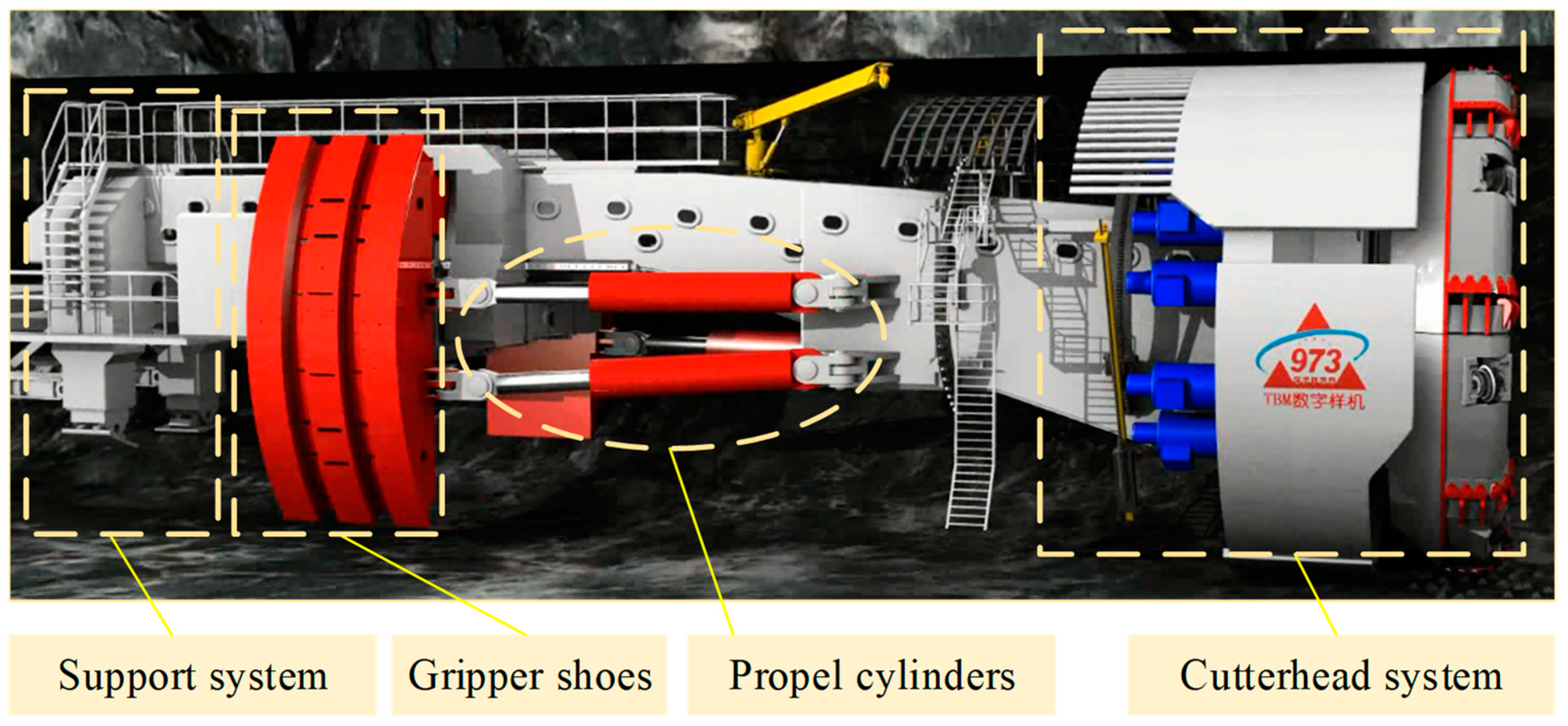
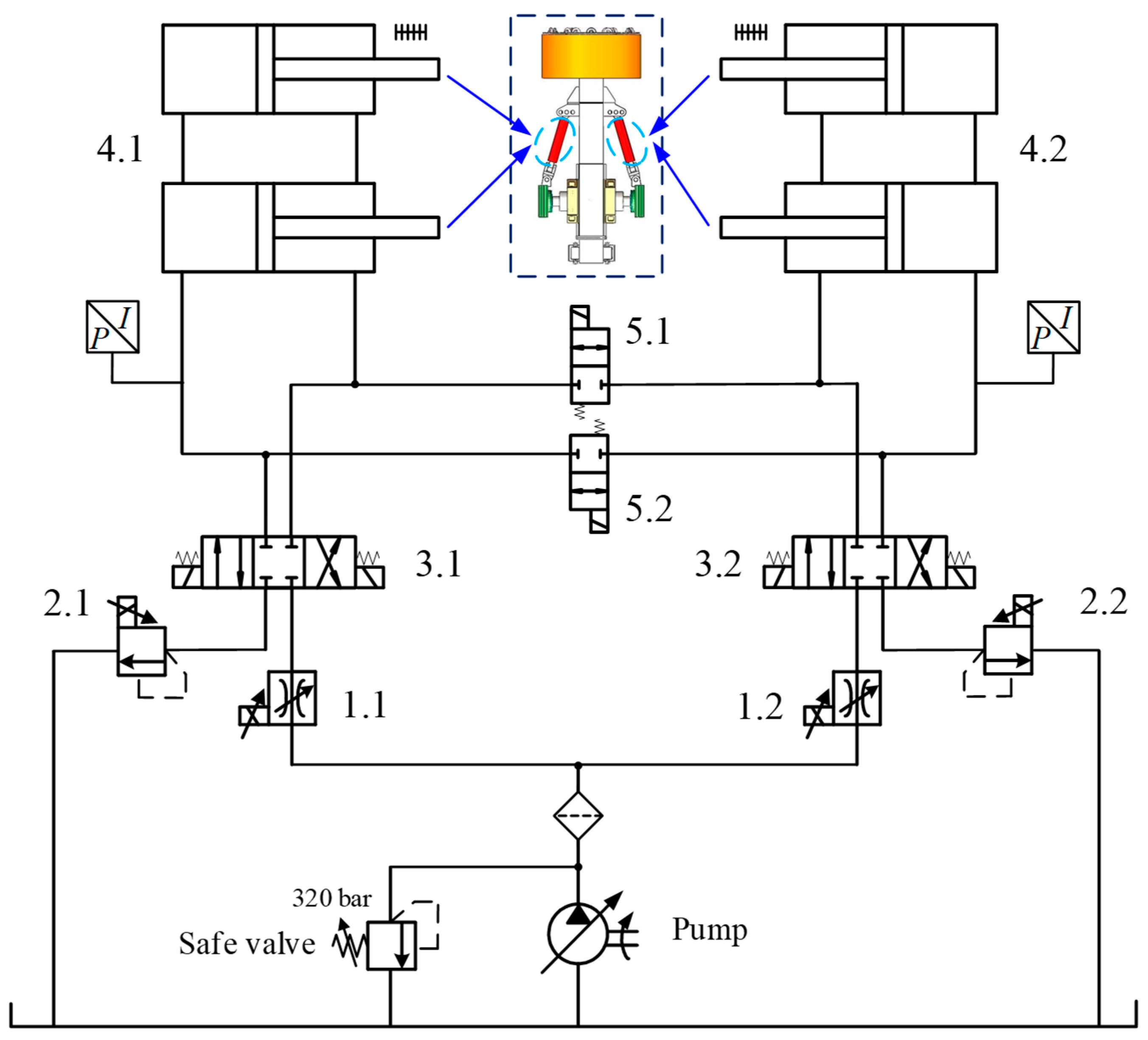
2. Description of the Thrust Hydraulic Control System

In a whole tunneling process, a TBM advances in complex rock environments, which leads to a continuous variation of thrust force and speed. A proportional flow control valve and proportional pressure relief valve are adopted in a thrust hydraulic control system to achieve smooth and stepless regulation effects. To control the thrust pressure and velocity precisely, the thrust hydraulic system works on the basis of a proportional pressure and flowrate regulation principle, which is determined by an appropriate setting of the proportional electromagnet of the proportional flow control valve and pressure relief valve. There are four propel cylinders, two on the left of the tunneling axis and two on the right, which drive the machine ahead while tunneling with gripper shoes sustaining the TBM on surrounding rocks.
The thrust hydraulic control system is mainly comprised of a pump, proportional flow control valve 1, proportional pressure relief valve 2, propel cylinders and oil pipe, as shown in Figure 2. The flow rate through valve 1 stays invariant if the input setting of the proportional flow control valve is fixed, which maintains the cylinder velocity at a constant level. In addition, parts of the hydraulic oil flow through valve 2 to build up the oil pressure and ensure it remains invariable, adjusted by the proportional pressure relief valve 2 in real time to reach the thrust demands. The signals of the pressure sensor and displacement sensor are delivered to the center control system with computers after acquisition. Then, the control signals of valves 1 and 2 are conducted to the coils of proportional valves 1 and 2, after operation of the control units, to complete the pressure and velocity regulation requirements efficiency.

3. Electrohydraulic Control System Design

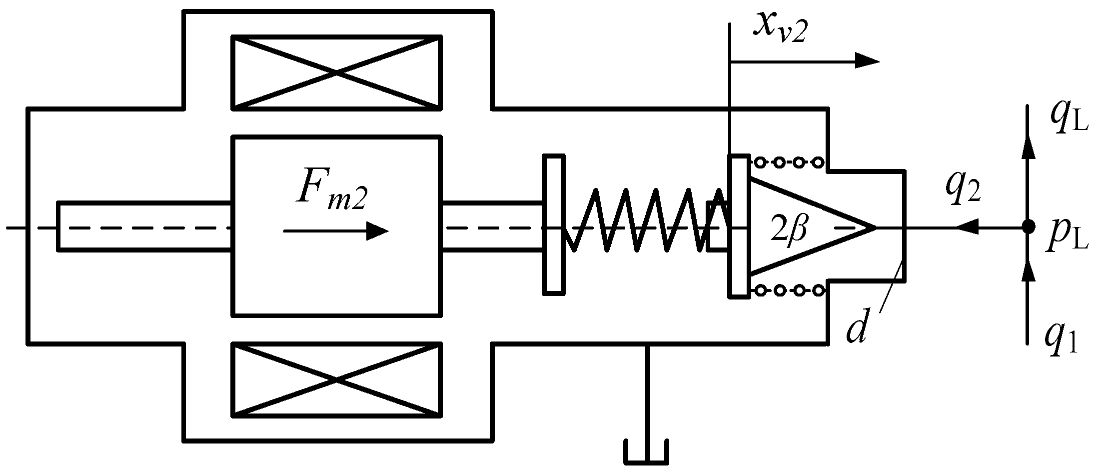
3.1. Mathematical Modeling

In the tunneling process, the output flow of the proportional flow control valve, which is just the oil flow through the orifice of the throttle valve inside the flow control valve, can be depicted as:
q 1 = K q 1 x v 1
where q1 is the flow rate, Kq1 is the valve flow gain and xv1 is the spool displacement.
By Newton’s laws of motion, we can find the dynamics equation of the spool as:
F m 1 = m 1 d 2 x v 1 d t 2 + D 1 d x v 1 d t + K 1 x v 1
where Fm1 denotes the output force of the solenoid of valve 1, m1 is the mass of the spool, D1 is the coefficient of viscous friction and K1 is the stiffness of spring.
The current characteristic equation of the proportional solenoid coil can be written as:
u = L d i d t + i R + K v d x v d t
where u denotes the output voltage of the solenoid coil, L is the inductance, R is the resistances of the coils and amplifier and Kv is the coefficient of velocity of the back electromotive force induced by the armature displacement.
Moreover, taking into account that the current–force characteristics of the proportional solenoid is approximately linear, the output electromagnetic force can be derived as
F m 1 = K F i
where Fm1 is the electromagnetic force, KF is the current force gain.
The structure principle diagram of the proportional pressure relief valve is shown in Figure 3. Given that the outlet pressure is zero, for the outline of the pressure relieve valve connected to the oil tank directly, then the oil flowing through valve 2 can be written as
q 2 = α A ( x v 2 ) 2 ρ p L
where q2 is the flow rate, α denotes the flow rate coefficient and A(xv2) is the effective flow area.
A(xv2) of valve 2 can be derived as:
A ( x v 2 ) = π x v 2 sin β ( d 1 2 x v 2 sin 2 β )
where xv2 is the spool displacement, β denotes the half-cone angle of the cone valve and d is the diameter of the orifice.
Substituting Equation (6) into Equation (5), we obtain:
q 2 = α π sin β ( d 1 2 x v 2 sin 2 β ) x v 2 2 p L ρ
The dynamics equation of the spool is revealed as:
p L A 0 F m 2 F f + K 2 ( x 0 x v 2 ) = m 2 d 2 x v 2 d t 2 + D 2 d x v 2 d t
where pL is the load pressure, A0 is the effect acting area of the poppet, Fm2 is the output force of the solenoid of valve 2, Ff is the steady-state fluid dynamic force, K2 is the total stiffness of the spring, x0 is the precompressed displacement of the spring, m2 is the mass of the moving body and D2 is the coefficient of viscous friction.
The flow equation of the cylinder is conducted as:
q L = A d x d t + C t c p L + V E d p L d t
where qL is the cylinder flow (load flow), A is the effective working area, x is the displacement of cylinder, Ctc is the coefficient of leakage, V is the total actuating volume and E is the effective bulk modulus.
The dynamics equation of the cylinder is written as:
A p L = M d 2 x d t + B v d x d t + K x + F L
where M is the total mass of the moving parts, Bv is the viscous damping coefficient, K is the stiffness of the load and FL is the load force.

3.2. Control Strategy

The working pressure and velocity of the thrust system should be regulated to adapt to different rock layers and mixed loads to balance safety and efficiency. The thrust system should attain the control parameters of the thrust speed on one hand and perform the pressure regulation to maintain the face stability on the other hand. To achieve favorable performance in the pressure and speed control system, which comprises controllers, amplifiers, valves, cylinders and sensors, a proper controller is employed to improve the system control characteristics.
The chamber pressure of propel cylinders can be regulated to adapt to different surrounding rock conditions by adjusting the electric current through the coils of the proportional pressure relief valve, especially when the TBM moves across two rock layers. The thrust pressure is set higher to resist the bigger thrust resistance force when marching in category I and II rock layers, which requires slower cylinder movements. Oppositely, a lower thrust pressure and a bigger cylinder velocity should be set when advancing in category III and IV rock layers to achieve a high efficiency and good economic benefits by varying the electric current into the proportional flow control valve and pressure relief valve.
A set of engineering data, from a water diversion project in Jilin province of China, is introduced here to reveal the changing process of thrust pressure and velocity. During the whole engineering project, the machine tunneled through several rock layers, including 191 m, 4125.7 m, 1822.5 m and 552 m of category II, III, IV and V rock layers, respectively, according to a prior geological survey, as drawn in Figure 4.
A qualified TBM should be equipped with a thrust hydraulic system adaptable to different rock layers and external sudden loads. The variation process of pressure and velocity of the thrust hydraulic control system is shown in Figure 5.
The interaction between the TBM and the surrounding rock conditions determines the tunneling quality [6]. The thrust force and speed must be variable according to the rock conditions. The pressure (force) and flow (velocity) are inherent coupling characteristics in the electrohydraulic system. To regulate the thrust pressure and velocity by the proportional pressure relief valve and proportional flow control valve, respectively, the pressure and flow compound control method was adopted. The signal of the working pressure of the propel cylinders detected by pressure sensors and likewise the displacement of the cylinders detected by displacement sensors were delivered back to the control units. The displacement signal should be differentiated to a velocity signal before feedback to the comparative unit without a doubt. The regulation of the pressure and flow rate was achieved synchronously. The control block diagram is shown in Figure 6.

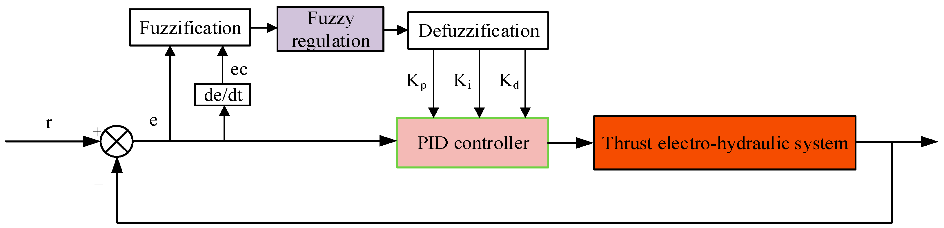
3.3. Design of the Fuzzy PID Controller

3.3.1. PID Controller Design

A conventional PID strategy has been widely used in industrial projects with its adaptability characteristics [26]. As to thrust control system, internal parameters such as fluid volume, which vary with the elastic modulus of oil and external load disturbances, which vary by advancing periods, bring a disadvantageous influence into the system [27]. In a conventional PID controller design, the parameters of the controller can be derived as follows:
u ( k ) = u ( k 1 ) + Δ u ( k )
Δ u ( k ) = K p ( e ( k ) e ( k 1 ) ) + K i e ( k ) + K d ( e ( k ) 2 e ( k 1 ) + e ( k 2 ) )
To improve the control characteristics of a thrust electrohydraulic system, a fuzzy PID controller was adopted in the control loop. The controller was customized for the thrust system, which required an appropriate modification of the fuzzy PID controller. In industrial applications, a self-tuning fuzzy PID is most widely used in electrohydraulic systems. The controller takes the error (defined as e) and change rate of error (defined as ec) as its input. The self-tuning fuzzy PID controller can adjust its parameters automatically to meet the system requirement when e and ec change in real time. The structure of a self-tuning fuzzy controller is shown in Figure 7.
In a sampling period, the deviation between the desired value and the practical value e and its change rate ec are settled as inputs, while the outputs are the change rate of the PID controller parameters, which are ΔkP, Δki and Δkd.

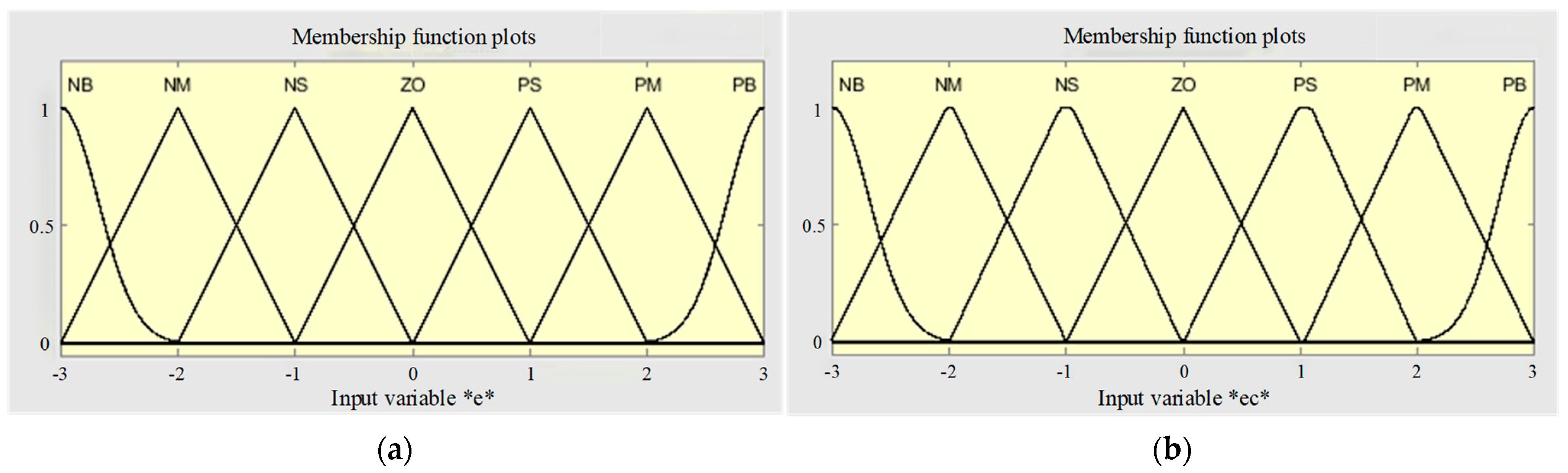
3.3.2. Definition of Domain and Membership

In this work, a general relative domain was adopted. The domain of the fuzzy PID controller must be formatted uniformly, combined with the real electrohydraulic control system. The input domain of e was set as {−3, 3} and the domain of ec was {−3, 3}. As for the output domain, the domain was determined as {−0.3, 0.3} of ΔkP, {−0.03, 0.03} of Δki and {−0.02, 0.02} of Δkd after several trials. The fuzzy subsets of variables were defined as {NB, NM, NS, ZO, PS, PM, PB}, which represent negative big, negative middle, negative small, zero, positive small, positive middle, positive big membership functions, respectively. The membership functions of the input variables are shown in Figure 8.

3.3.3. Fuzzy Control Rules

The fuzzy rules were derived from engineering experience at first. After some test trials, the fuzzy rules were modified and finally confirmed. Table 1 shows the fuzzy control rules. The outputs of the fuzzy control system change the parameters of the PID controllers, which enhances the control characteristics of the electrohydraulic thrust system.

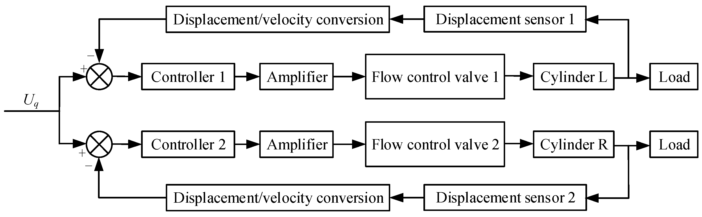
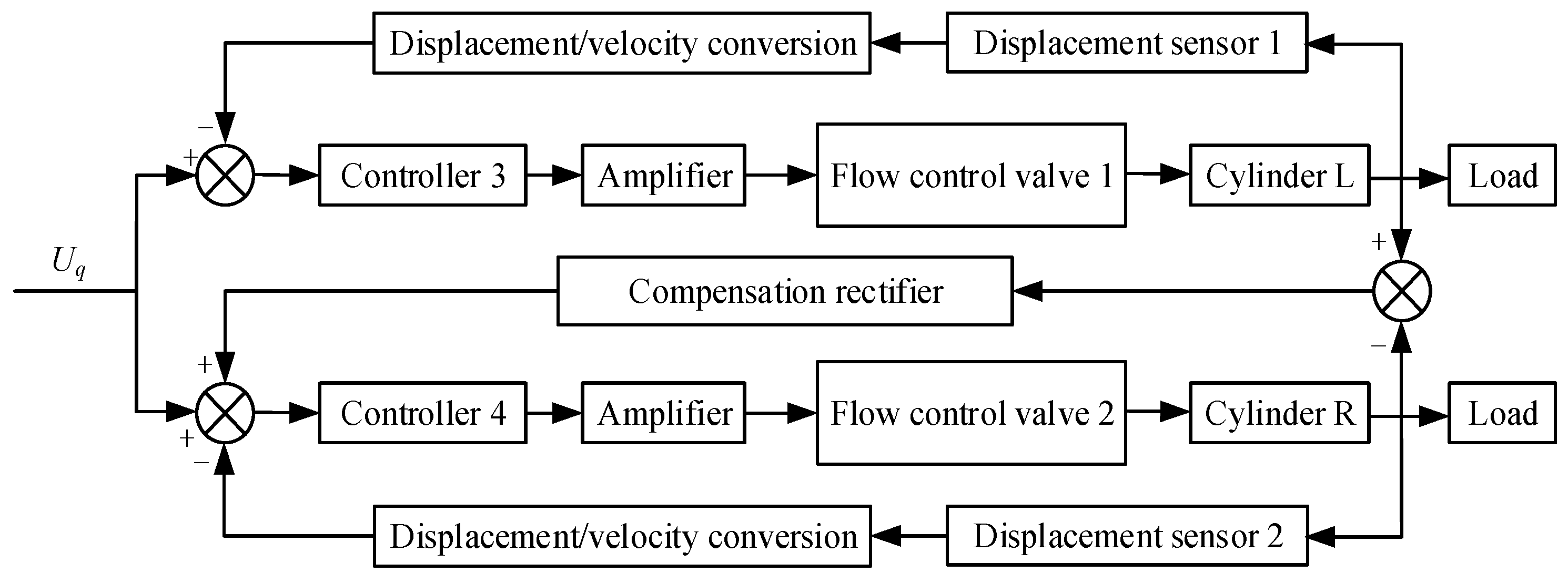
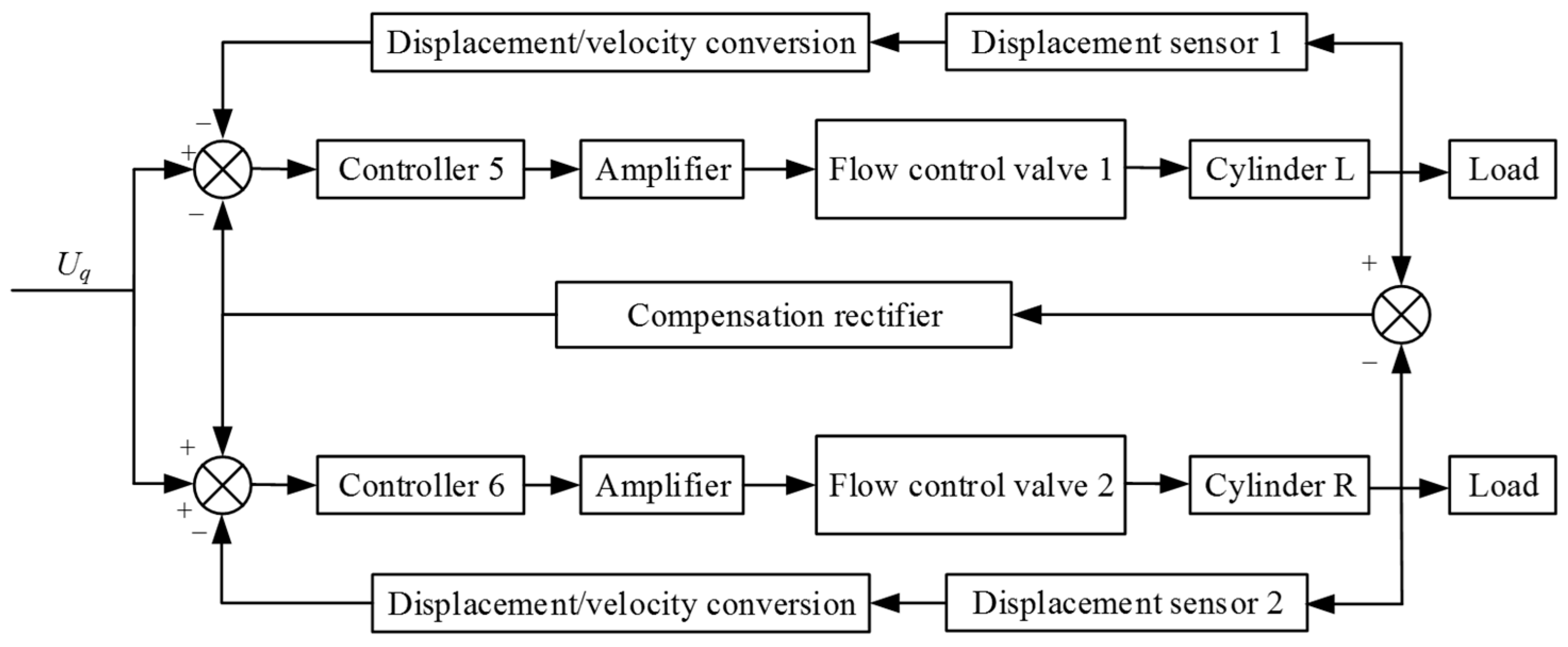
4. Synchronous Motion Control of Propel Cylinders

The thrust system consists of four propel cylinders with two on the right of the vertical axis and the other two on the left, as mentioned in Section 2. Different from the dual-cylinder transmission systems researched in other existing works, the propel cylinders in the thrust system of a TBM bear heavy loads and mechanical vibration disturbances from the main mechanical structure of the TBM. Thus, the thrust forces of the two sides must be in conformity with vibration disturbances in practical tunnel engineering. In order to ravel out the kinematic chain of the thrust system, the geometric description is shown in Figure 9 while the machine tunnels along a straight-line-type tunnel.
When the TBM marches ahead, the geometrical relationship of the two left cylinders’ displacement can be represented as:
{ tan θ L 1 = x 1 R r l L 1 2 = ( R r ) 2 + x 1 2 l L 2 2 = ( R r ) 2 + ( x 1 + x 2 ) 2
As to the right cylinders, the dimension relationship can be derived as:
{ tan θ R 1 = x 1 R r l R 1 2 = ( R r ) 2 + x 1 2 l R 2 2 = ( R r ) 2 + ( x 1 + x 2 ) 2
The displacement of the right cylinders and left cylinders are consistent in value when the TBM advances on a straight line theoretically. The dynamics equation of the cylinders in the horizontal plane can be written as:
{ A p L i sin θ L i + A p R i sin θ R i = m d 2 x d t + B x d x d t + k x x + F x i A p R i cos θ R 1 A p L i cos θ L i = m d 2 x d t + B y d y d t + k y y + F y i , i = 1 , 2
where pLi is the pressure of the left cylinder, pRi is the pressure of the right cylinder, A is the effective working area of the cylinder, m is the mass of the TBM, Bx is the coefficient of viscous friction in the x-axis direction, By is the coefficient of viscous friction in the y-axis direction, kx is the stiffness of the load in the x-axis direction, ky is the stiffness of the load in the y-axis direction, Fxi is the load force in the x-axis direction and Fyi is the load force in the y-axis direction.
Mostly in engineering applications, the dual cylinders are controlled by human-operated proportional valves in electrohydraulic systems, in which the control effect is strongly dependent on the machine drivers. The synchronization control is being ignored in most engineering situations, which is regarded as absolute synchronization under the mechanical steel structure. If the synchronization control can be applied positively into thrust electrohydraulic systems, the decrease in imbalance impacts on the cylinders and the promotion of safety can be achieved in predictable ranges.
To realize synchronization control of dual cylinders, the simplest way is to synchronize the cylinders with the hydraulic circuit itself. The signal from the displacement of the right and left propel cylinders are detected by displacement sensors individually and then delivered back to the control units, which constitutes the closed-loop control system, as shown in Figure 10. To distinguish from the control system introduced below, this control system is called independent synchronization control system or ISCS for short.
In general results of synchronization control systems, an ISCS cannot reach the control goal of synchronization, because of the independence of the closed control loop. To associate control of the left and right cylinders, one side of the cylinders is chosen as the positive referential object, while the other side of cylinders is selected as passive, following the other one. With the left and right cylinders assigned in mirrored position, whether the right cylinders or the left ones are chosen as positive referential objects yields the same control effects. This system is defined as a SRSCS, short for single referential synchronization control system. Figure 11 depicts the control loops of a SRSCS.
Moreover, coupling the control of the right and left cylinders together may promote the response speed and decrease the control error of the thrust electrohydraulic system under reasonable thinking. The CRSCS, short for coupled referential synchronization control system, is proposed, by coupling the synchronization control of both sides. The control method is shown in Figure 12.

5. Experimental Results and Analysis

5.1. Test Rig Design
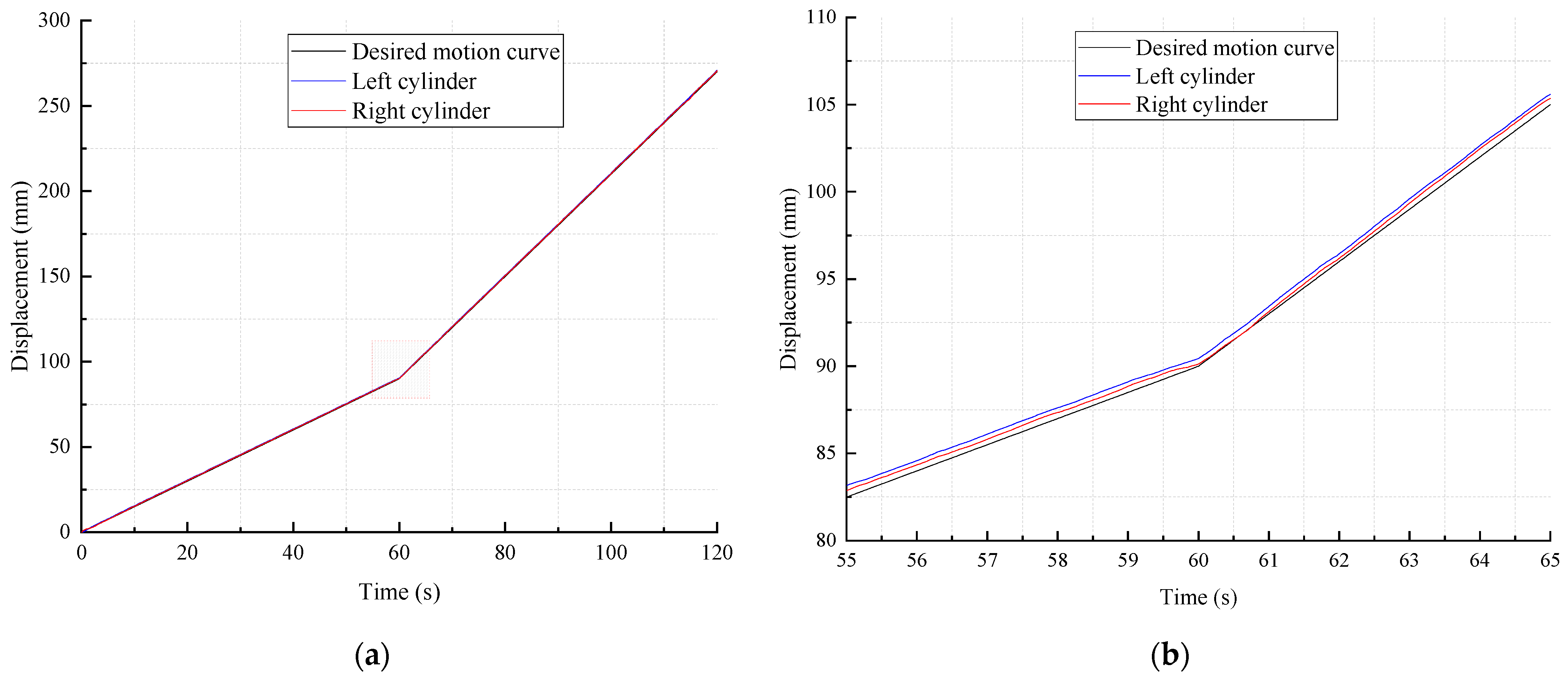
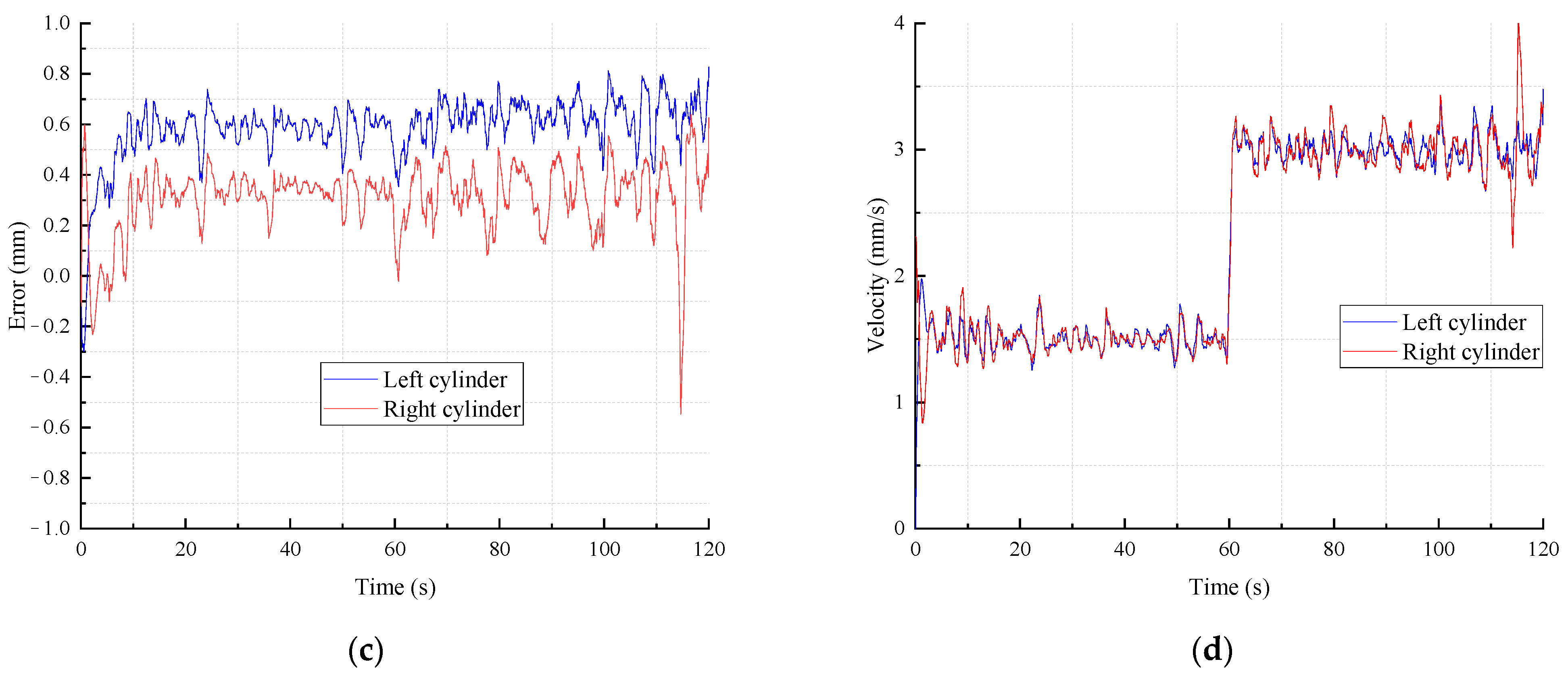
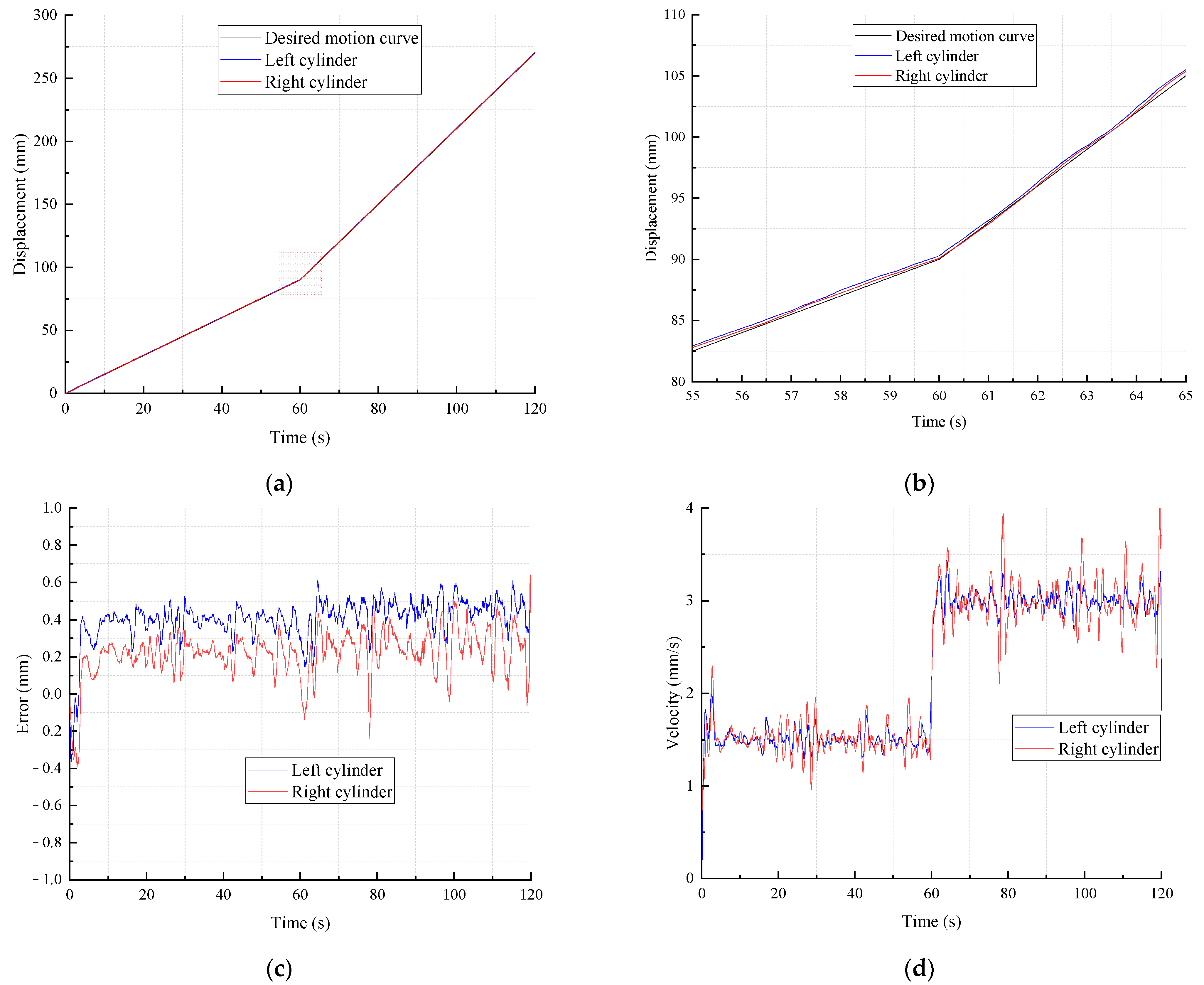
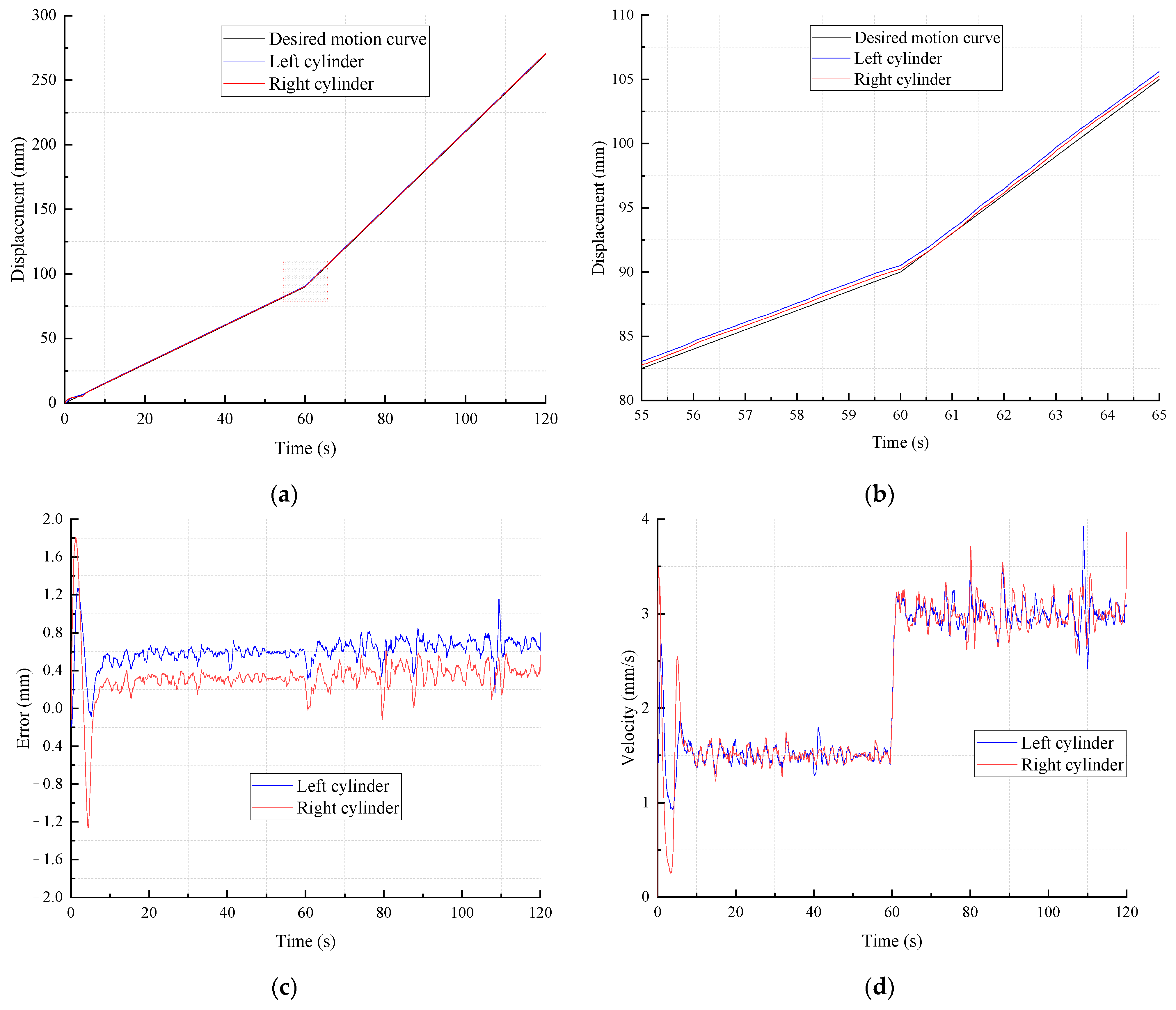
In this project, a test rig of a TBM was built up to simulate the real machine. Figure 13 shows the test rig, which contains the mechanical structure, hydraulic pump-valve station and electrical cabinets. The Ø2.5 m scaled TBM test rig consists of four dominating systems: a cutterhead system, a support and gripper system, a thrust system and a load simulation system. The load simulation system simulates thrust and torque load while tunneling by a shell structure with hydraulic cylinders and motors. The thrust system consists of four propel cylinders with two on the right of the vertical axis and the other two on the left. The whole tunneling process including advancing, supporting and shifting to next step can be achieved proportionally to tunnel engineering TBMs conveniently. Table 2 shows the main parameters of the thrust electrohydraulic system of the Ø2.5 m scaled TBM test rig.
As mentioned before, in existing TBMs, four cylinders are controlled by identical proportional flow control and pressure relief valves. In order to explore the synchronization control of the thrust system, the right cylinders and left cylinders can be regulated by two separate groups of proportional flow control and pressure relief valves. As shown in Figure 14, with the electromagnets of valve 5.1 and 5.2 charged and directional valve 3.2 remaining in the middle operating position, the test rig can simulate existing thrust electrohydraulic systems, in which four cylinders are controlled by proportional flow control valve 1.1 and pressure relief valve 2.1 uniformly. In this situation, the working pressure and flowrate of the propel cylinders are identical. The movements of the four propel cylinders are constrained by the mechanical structure of the TBM.
To investigate the synchronization motion control of the thrust system, the electromagnets of valves 5.1 and 5.2 were discharged. The hydraulic characteristic parameters of the two left cylinders 4.1 are determined by proportional flow control valve 1.1 and pressure relief valve 2.1, while proportional flow control valve 1.2 and pressure relief valve 2.2 control the pressure and flowrate of the two right cylinders.

5.2. Test Results

The thrust pressure regulation tests were carried out on the Ø2.5 m scaled TBM test rig. Figure 15 shows the geological conditions of a water diversion project, as mentioned in Section 2, in the Jilin province of China. Different sections in different colors represents the rock layers in the project. The darker the section, the harder the surrounding rock circumstance is. The TBM hydraulic systems suffers intensive load impacts, especially when the machine crosses disparate rock layers.
The synchronization motion behavior of ISCS, SRSCS and CRSCS are shown in Figure 16, Figure 17 and Figure 18. Taking into account the engineering conditions and control, the synchronization motion control was divided into two phases: phase 1 from time 0 s to 60 s with a velocity of 1.5 mm/s; phase 2 from time 60 s to 120 s with a velocity of 3 mm/s. It can be seen that there was no explicit effect of the three synchronization motion control systems when the velocity of the propel cylinders vary, which means the three synchronization motion control systems were competent during the whole tunneling process while the velocity varies. A velocity oscillation existed in the three systems, caused by the nonlinearity of the electrohydraulic system, such as the influence of the hydraulic oil bulk modulus and the complexity of the characteristics of the load. On the other aspect, mechanical vibration occurred inevitably, caused by the large inertia of the whole TBM during the cutting process of the cutterhead system.
In order to observe the control effects of the synchronization motion control in the three systems more precisely, the displacement error of the left cylinders in the three synchronization motion control systems was extracted and is illustrated in Figure 19. More characteristics of the control effects of the synchronization motion control in the three systems are shown in Table 3. In the ISCS system, it takes 10.6 s to maintain the relative steady state with about 0.6 mm of displacement error. In the SRSCS system, the settling time goes to 8.0 s with a 0.4 mm displacement error, while the settling time goes to 13.6 s with a 0.6 mm displacement error in the CRSCS system. At the beginning phase when the hydraulic oil is compressed to build system pressure, the displacement error shows more variation in amplitude with a 1.27 mm displacement error in the CRSCS system. The overshoot is much bigger compared to the other two systems.
According to the results above, coupling the control of the two sides of the cylinders in the CRSCS system do not improve the control characteristics. On the contrary, because of the coupling, the oscillation of the displacement is bigger. The control objects are hydraulic cylinders in a electrohydraulic system, with a big inertia and small dynamic motion velocity, which makes the CRSCS system more unstable and harder to control.
In general, the three control systems were qualified for the synchronization motion control of a Ø2.5 m machine and a 500 mm stroke with less than 1 mm of displacement difference in the advancing process. The SRSCS control system showed the best superiority in reducing vibrations and a shorter time to settle to stable working conditions, which extends the TBM’s life and affects the acceleration of the tunneling process.

6. Conclusions

In this study, an electrohydraulic thrust system for a TBM was proposed to achieve the engineering requirements. After the mathematical modeling and fuzzy PID controller design, three synchronization motion control systems, ISCS, SRSCS and CRSCS were developed. Then, a Ø2.5 m scaled TBM test rig was built to verify the control systems. Finally, comparative tests of the three systems were carried out. The closed-loop control scheme with a proportional flow control valve and a pressure relief valve proved to be qualified for reaching a desired stable performance in the thrust tunneling process. The three control systems sustained low synchronization errors by applying controllers to the control units to compensate the displacement error. The test results showed that the SRSCS achieved the best control performance. The steady-state displacement error decreased by about 33.3% in contrast to the ISCS and CRSCS. Generally, the study indicated that the proposed methods of controlling the tunneling thrust process for TBM were effective theoretically and in practice. The SRSCS has the most potential for the synchronization motion control of a thrust electrohydraulic system for a TBM.

Author Contributions

Conceptualization, W.W.; software, W.W. and Q.H.; writing—original draft preparation, W.W.; writing—review and editing, Y.C., X.Z. and X.P.; supervision, G.G.; project administration, G.G. All authors have read and agreed to the published version of the manuscript.

Funding

This research was funded by National Key Research and Development Program of China, grant no. 2020YFF0218003, National Natural Science Foundation of China, grant no. 52105074, National Key Research and Development of China, grant no. 2020YFB1713903, Open Project of State Key Laboratory of Shield Machine and Boring Technology, grant no. SKLST-2021-K02 and Natural Science Foundation of Guangdong Province, grant no. 2021A1515010818.

Institutional Review Board Statement

Not applicable.

Informed Consent Statement

Not applicable.

Data Availability Statement

The data presented in this study are available on request from the corresponding author.

Conflicts of Interest

The authors declare no conflict of interest.

References

  1. Mahmoodzadeh, A.; Mohammadi, M.; Ibrahim, H.H.; Abdulhamid, S.N.; Ali, H.F.H.; Hasan, A.M.; Khishe, M.; Mahmud, H. Machine learning forecasting models of disc cutters life of tunnel boring machine. Autom. Constr. 2021, 128, 103779. [Google Scholar] [CrossRef]
  2. Wang, F.; Gong, G.; Duan, L.; Qin, Y. XGBoost. J. Zhejiang Univ. 2020, 54, 633–641. [Google Scholar]
  3. Rostami, J.; Dreyer, C.; Duhme, R.; Khorshidi, B. Challenges of Designing a Tunnel Boring Machine (TBM) for Development of Under-ground Structures on the Moon; CRC Press/Balkema: Naples, Italy, 2019; pp. 4206–4217. [Google Scholar]
  4. Armaghani, D.J.; Azizi, A. An Overview of Field Classifications to Evaluate Tunnel Boring Machine Performance; Springer: Berlin/Heidelberg, Germany, 2021; pp. 1–16. [Google Scholar] [CrossRef]
  5. Grasmick, J.; Mooney, M. A Probabilistic Geostatistics-Based Approach to Tunnel Boring Machine Cutter Tool Wear and Cutterhead Clogging Prediction. J. Geotech. Geoenvironmental Eng. 2021, 147, 05021014. [Google Scholar] [CrossRef]
  6. Koopialipoor, M.; Fahimifar, A.; Ghaleini, E.N.; Momenzadeh, M.; Armaghani, D.J. Development of a new hybrid ANN for solving a geotechnical problem related to tunnel boring machine performance. Eng. Comput. 2020, 36, 345–357. [Google Scholar] [CrossRef]
  7. Wang, L.; Sun, W.; Long, Y.; Yang, X. Reliability-Based Performance Optimization of Tunnel Boring Machine Considering Geological Uncertainties. IEEE Access 2018, 6, 19086–19098. [Google Scholar] [CrossRef]
  8. Armaghani, D.J.; Faradonbeh, R.S.; Momeni, E.; Fahimifar, A.; Tahir, M.M. Performance prediction of tunnel boring machine through developing a gene expression programming equation. Eng. Comput. 2017, 34, 129–141. [Google Scholar] [CrossRef]
  9. Khorasani, E.; Azali, S.T.; Naghadehi, M.Z.; Jalali, S.E.; Jimenez, R.; Zare, S. Performance analysis of tunnel-boring machine by probabilistic systems approach. Proc. Inst. Civil Eng. Geotech. Eng. 2018, 171, 422–438. [Google Scholar] [CrossRef]
  10. Shi, H.; Yang, H.; Gong, G.; Liu, H.; Hou, D. Energy saving of cutterhead hydraulic drive system of shield tunneling machine. Autom. Constr. 2014, 37, 11–21. [Google Scholar] [CrossRef]
  11. Shi, H.; Yang, H.; Gong, G.; Wang, L. Key technologies of shield tunneling machine and present status and prospect of test rigs for tunneling simulation. J. Zhejiang Univ. 2013, 47, 741–749. [Google Scholar]
  12. Wang, L.; Gong, G.; Shi, H.; Yang, H. Modeling and analysis of thrust force for EPB shield tunneling machine. Autom. Constr. 2012, 27, 138–146. [Google Scholar] [CrossRef]
  13. Lee, G.-J.; Ryu, H.-H.; Kwon, T.-H.; Cho, G.-C.; Kim, K.-Y.; Hong, S. A Newly Developed State-of-the-Art Full-Scale Excavation Testing Apparatus for Tunnel Boring Machine (TBM). KSCE J. Civ. Eng. 2021, 25, 4856–4867. [Google Scholar] [CrossRef]
  14. Sharghi, M.; Chakeri, H.; Afshin, H.; Ozcelik, Y. An experimental study of the performance of two-component backfilling grout used be-hind the segmental lining of a tunnel-boring machine. J. Test Eval. 2018, 46, 2083–2099. [Google Scholar] [CrossRef]
  15. Liao, J.; Bai, K.; Xia, Y.; Li, H.; Zhao, X.; Xiao, X.; Wang, Y. Flow field characteristics of an agitator system of a large diameter slurry-water shield machine. J. Mech. Sci. Technol. 2021, 35, 1501–1513. [Google Scholar] [CrossRef]
  16. Men, Y.; Wang, Y.; Zhou, J.; Liao, S.; Zhang, K. Measurement and analysis on EPB shield machine tunneling efficiency in Jinan composite stratum. China Civil Eng. J. 2019, 52, 110–119. [Google Scholar]
  17. Huo, J.; Zhou, L.; Zhu, D.; Zhang, W.; Wang, W.; Sun, W. Cutterhead opening mode design of a composite earth pressure balance shield machine. J. Harbin Eng. Univ. 2017, 38, 433–439. [Google Scholar]
  18. Lyu, L.; Chen, Z.; Yao, B. Advanced Valves and Pump Coordinated Hydraulic Control Design to Simultaneously Achieve High Accuracy and High Efficiency. IEEE Trans. Control Syst. Technol. 2020, 29, 236–248. [Google Scholar] [CrossRef]
  19. Lyu, L.; Chen, Z.; Yao, B. Development of Pump and Valves Combined Hydraulic System for Both High Tracking Precision and High Energy Efficiency. IEEE Trans. Ind. Electron. 2018, 66, 7189–7198. [Google Scholar] [CrossRef]
  20. Hou, D.; Gong, G.; Shi, H.; Wang, L. Design of new propulsion system of shield tunneling machine based on compliance characteristics. J. Zhejiang Univ. 2013, 47, 1287–1292. [Google Scholar]
  21. Wang, R.; Guo, X.; Li, J.; Wang, J.; Jing, L.; Liu, Z.; Xu, X. A mechanical method for predicting TBM penetration rates. Arab. J. Geosci. 2020, 13, 1–15. [Google Scholar] [CrossRef]
  22. Liu, B.; Wang, Y.; Zhao, G.; Yang, B.; Wang, R.; Huang, D.; Xiang, B. Intelligent decision method for main control parameters of tunnel boring machine based on multi-objective optimization of excavation efficiency and cost. Tunn. Undergr. Space Technol. 2021, 116, 104054. [Google Scholar] [CrossRef]
  23. Zhang, L.; Li, Y. Synchronous Control of Double Hydraulic Cylinders of Scissors Aerial Work Platform Based on Fuzzy PID. In Proceedings of the 5th International Conference on Electromechanical Control Technology and Transportation (ICECTT), Nanchang, China, 15–17 May 2020; pp. 349–354. [Google Scholar]
  24. Wang, L.; Zhao, D.; Liu, F.; Liu, Q.; Zhang, Z. Active Disturbance Rejection Position Synchronous Control of Dual-Hydraulic Actuators with Unknown Dead-Zones. Sensors 2020, 20, 6124. [Google Scholar] [CrossRef]
  25. Wanling, L.; Hongmei, W.; Huaying, Q.; Lihua, J. Research on Key Technologies of Double-cylinder Synchronous Hydraulic Machine. J. Phys. Conf. Ser. 2020, 1676, 012144. [Google Scholar] [CrossRef]
  26. Luo, Q.; Li, W.; Su, H.; Chen, X. Evaluating Construction Risks of Modified Shield Machine Applicable to Soft Soils Based on Fuzzy Comprehensive Evaluation Method. Math. Probl. Eng. 2020, 2020, 1–15. [Google Scholar] [CrossRef]
  27. Do, N.A.; Dias, D.; Vu, T.T.; Dang, V.K. Impact of the shield machines performance parameters on the tunnel lining behaviour and settlements. Environ. Earth Sci. 2021, 80, 16. [Google Scholar] [CrossRef]
Figure 1. Schematic structure diagram of a tunnel boring machine.
Machines 10 00119 g001
Figure 2. Schematic diagram of the thrust hydraulic system.
Machines 10 00119 g002
Figure 3. Structure principle diagram of the proportional pressure relief valve.
Machines 10 00119 g003
Figure 4. Different rock layers’ proportion in the engineering project.
Machines 10 00119 g004
Figure 5. Variation of pressure and velocity of the thrust hydraulic control system in the tunnel engineering project: (a) thrust pressure variation; (b) thrust velocity variation.
Machines 10 00119 g005
Figure 6. Block diagram of the thrust control system.
Machines 10 00119 g006
Figure 7. Structure of self-tuning fuzzy PID controller.
Machines 10 00119 g007
Figure 8. Membership functions of fuzzy PID inputs: (a) membership functions of e; (b) membership functions of ec.
Machines 10 00119 g008
Figure 9. Dimensional drawing of propel cylinders when tunneling straight.
Machines 10 00119 g009
Figure 10. Block diagram of the synchronization control system of an ISCS.
Machines 10 00119 g010
Figure 11. Block diagram of the synchronization control system of a SRSCS.
Machines 10 00119 g011
Figure 12. Block diagram of the synchronization control system of a CRSCS.
Machines 10 00119 g012
Figure 13. The Ø2.5 m scaled TBM test rig. (a) Overall sight of the Ø2.5 m scaled TBM test rig. (b) Mechanical structure.
Machines 10 00119 g013
Figure 14. Simplified hydraulic driving system of the propel cylinders.
Machines 10 00119 g014
Figure 15. Geological sectional drawing of the tunneling project.
Machines 10 00119 g015
Figure 16. Synchronization motion behavior of ISCS: (a) displacement of cylinders in two sides; (b) feature figure of displacement of cylinders when the velocity changes; (c) displacement error under synchronization motion control; (d) velocity of cylinders under synchronization motion control.
Machines 10 00119 g016aMachines 10 00119 g016b
Figure 17. Synchronization motion behavior of SRSCS: (a) displacement of cylinders in two sides; (b) feature figure of displacement of cylinders when the velocity changes; (c) displacement error under synchronization motion control; (d) velocity of cylinders under synchronization motion control.
Machines 10 00119 g017
Figure 18. Synchronization motion behavior of CRSCS: (a) displacement of cylinders in two sides; (b) feature figure of displacement of cylinders when the velocity changes; (c) displacement error under synchronization motion control; (d) velocity of cylinders under synchronization motion control.
Machines 10 00119 g018
Figure 19. Displacement error of left cylinders in three synchronization motion control systems.
Machines 10 00119 g019
Table 1. Fuzzy control rules.
eec
NBNMNSZOPSPMPB
NBPB/NB/PSPB/NB/NMPM/NM/NBPM/NM/NBPS/NS/NBZO/NS/NMZO/ZO/PS
NMPB/NB/PSPM/NM/NMPM/NM/NBPS/NS/NMPS/NS/NMZO/ZO/NSNS/PS/ZO
NSPM/NM/ZOPM/NM/NSPS/NS/NMPS/NS/NMZO/ZO/NSNS/PS/NSNS/PS/ZO
ZOPM/NM/ZOPS/NS/NSPS/NS/NSZO/ZO/NSNS/PS/NSNS/PS/NSNM/PM/ZO
PSPS/NS/ZOPS/NS/ZOZO/ZO/ZONS/PS/ZONS/PS/ZONM/PM/ZONM/PM/ZO
PMPS/NS/PBZO/ZO/NSNS/PS/PSNS/PS/PSNM/PM/PSNM/PM/PSNB/PB/PB
PBZO/ZO/PBNS/PS/PMNS/PS/PMNM/PM/PMNM/PM/PMNB/PB/PSNB/PB/PB
Table 2. Main parameters of the thrust electrohydraulic system of the Ø2.5 m scaled TBM test rig.
ParameterValueUnit
Rod diameter of propel cylinder180mm
Inside bore diameter of propel cylinder125mm
Stroke of propel cylinder530mm
Max. control pressure of flow control valve350bar
Max. flowrate of flow control valve16L/min
Max. output current of solenoid of flow control valve680mA
Max. control pressure of pressure relief valve350bar
Max. flowrate of pressure relief valve30L/min
Max. output current of solenoid of pressure relief valve1600mA
Max. thrust force (4 cylinders in total)2000KN
Table 3. Control effects of synchronization motion control in three systems.
CharacteristicsISCSSRSCSCRSCS
Overshoot0.69 mm0.43 mm1.27 mm
Settling time10.6 s8.0 s13.6 s
Steady error0.6 mm0.4 mm0.6 mm
Publisher’s Note: MDPI stays neutral with regard to jurisdictional claims in published maps and institutional affiliations.

