Abstract
This study investigates the influence of salt (NaCl) and, separately, frother (α-terpineol) on flotation of copper-bearing shale. It was shown, as expected, that increasing concentration of either NaCl or α-terpineol improves both ultimate shale recovery and the kinetics of flotation, except for very high frother concentrations, which lead to a drop in flotation. It appears that the relationship between the first-order flotation rate constant and ultimate recovery for both applied reagents follows the same pattern regardless of the different mechanisms of NaCl and frother action.
1. Introduction
Flotation is one of the key methods for enriching mineral raw materials and is widely used in the mining industry, especially for the recovery of metals from ores with low concentrations of valuable elements. This process utilizes differences in the wettability of mineral particles, allowing their separation in an aqueous environment through the introduction of air and appropriate reagents, including frothers and salts [1,2,3,4,5,6,7,8,9,10,11,12,13,14].
Copper-bearing shale, which is one of the lithological fractions extracted by Polish copper ore mines, is characterized by a complex mineralogical structure with a high content of valuable components and often the highest copper concentration among ore rocks. It also contains fine-grained mineralization, clay fractions, and a significant amount of organic carbon, which creates challenges during processing. The effective flotation of this material requires the optimization of process parameters, including the frother concentration, which significantly affects the separation dynamics and enrichment efficiency [15,16].
Polish copper-bearing shale is a sedimentary rock formed from the deposits of the Zechstein Sea, later secondarily mineralized by hydrothermal fluids, which resulted in ore formation [17]. These formations originated during the Zechstein period (Permian), around 250 million years ago, when a vast sedimentary basin existed in what is now Poland. Fine-grained clay materials, carbonates, and organic substances were deposited there. The main area of occurrence is the Fore-Sudetic Monocline, covering the mining district around Lubin, Polkowice, and Głogów. The first reports of copper-bearing shales in the Lower Silesia region appeared at the turn of the 19th and 20th centuries, but intensive exploration began only in the 1950s with the establishment of the KGHM Polska Miedź mining and metallurgical complex [18]. Globally, copper-bearing shales occur in various regions, including Africa (Zambia, Democratic Republic of the Congo) and South America (Chile) [19].
The flotation literature devotes much attention to recovery efficiency and the quality of concentrates but is less focused on the kinetics of the process [20]. Analyzing the flotation rate constant of copper shale as a function of the frother and salt concentrations present in industrial flotation may contribute to a better understanding of the process and its optimization.
Copper-bearing shale contains a variety of mineral and chemical components that determine its industrial value:
- Copper minerals: Chalcopyrite, bornite, covellite, chalcocite, digenite—total copper content ranges from 2% to over 7% [21];
- Accompanying metals: Silver, lead, zinc, cobalt, molybdenum, gold, etc. [18];
- Clay minerals: Mainly illite [15];
- Carbonate minerals: Dolomite, calcite, etc. [15];
- Organic substances: Bitumen and structureless material [15].
Copper-bearing shale is one of the most difficult materials to enrich due to its mineralogical complexity and the presence of organic substances and fine-grained minerals. According to Pawlos et al. [16], the main processing issues associated with copper shale include the following:
- Low beneficiation capacity due to very fine mineralization: Copper minerals in shale are fine-crystalline, often smaller than 20 µm, making liberation during grinding and subsequent recovery by flotation difficult. The shale contains relatively high concentrations of copper and accompanying metals such as silver or molybdenum, but their recovery is challenging. As a result, the copper content in the concentrate is lower than theoretically possible.
- Presence of organic substances in shales: They are naturally hydrophobic, causing easy transfer to the concentrate and, thus, reducing its quality. Additionally, organic substances absorb flotation reagents, increasing their consumption and reducing process efficiency.
- Clay minerals present in the shale form hydrophilic coatings on copper mineral grains, hindering their attachment to air bubbles. This results in copper losses and lower flotation efficiency. Moreover, clay minerals are mechanically carried into the froth product or float as aggregates with organic matter, negatively affecting concentrate quality.
- The variable composition of shale within the deposit causes difficulties in maintaining a stable enrichment process. This variability applies to both the content of copper minerals and physicochemical properties.
As one of the main lithological formations exploited by KGHM, copper shale plays a significant role in providing copper and accompanying metals. Despite its high content of valuable components, it poses challenges in beneficiation, and its capacity is the lowest among all lithological ore fractions mined by KGHM. Therefore, a thorough understanding of its flotation-related properties is crucial, as the effectiveness and efficiency of this process are key to the optimal utilization of the rich deposits in Lower Silesia, Poland.
Flotation kinetics concerns the study of the flotation process rate, i.e., the change in the mass of floated particles in the flotation cell over time. Process analysis involves examining the rates of individual phenomena occurring during flotation, such as collisions, attachment, and detachment of mineral particles from air bubbles. The key objective of flotation kinetics research seems to be modeling the relationship between flotation time and mineral recovery. This enables the prediction of flotation outcomes, process optimization, and better understanding of how operating parameters influence efficiency. The importance of flotation kinetics increases with the need to improve industrial performance and broaden the applications of flotation technologies [22,23].
The flotation kinetics is usually characterized by means of the flotation rate constant k, which describes the speed at which mineral particles transfer into the froth. It is a crucial parameter in kinetic models because it helps to determine how quickly minerals proceed through each stage of the process.
The flotation rate constant is the product of three main factors:
- The number of bubble–particle collisions per unit of time and volume;
- The probability of particle adhesion to the bubble surface;
- The probability of bubble–particle aggregate stability.
The value of k depends on the physicochemical properties of the minerals, such as grain size and hydrophobicity, as well as operational conditions like turbulence in the flotation cell, bubble size, speed, and quantity, as well as froth stability [24,25]. There are many models describing flotation kinetics, which can be divided into three main categories: empirical, probabilistic, and kinetic models. Empirical models are based on experimental data but have limited predictive capability under variable conditions. Probabilistic models take into account the probabilities of elementary flotation events, such as the likelihood of particle–bubble collisions. However, they require large datasets, advanced calculations, and precise knowledge of physical parameters, which is challenging when many variables are involved. Simpler probabilistic models resemble basic kinetic models, which describe flotation using analogies to chemical reactions. Kinetic models are advantageous due to their simplicity, good fit, consideration of key variables, ability to correlate data, and effective transfer of optimization results to industrial practice. Kinetic model equations primarily involve the following parameters:
- -
- The order of the equation—n;
- -
- The flotation rate constant—k;
- -
- Recovery after a given flotation time—R(t);
- -
- Ultimate recovery (achieved after theoretically infinite flotation time;
- -
- A thermodynamic property—R∞.
The general form of the equation used to describe batch flotation kinetics can be written as [26,27]
where the following definitions are used:
C(t)—the concentration of floatable particles still in the flotation cell at time t;
k—the flotation rate constant;
n—the kinetic order of the flotation process.
Selecting an appropriate kinetic model equation is essential [23,25]. However, most flotation data can be well approximated with the first-order kinetics (n = 1) [26,27,28]. This is the most commonly used model, especially since it does not require knowledge of the initial concentration C. It assumes a constant bubble concentration and that collision frequency depends mainly on the number of remaining particles.
The first-order model can be expressed as
In simple terms, for a kinetic model described by the same equation, k indicates the flotation rate, while R∞ indicates flotation power [27]. In Figure 1I, all experimental flotation curves reach the same recovery after infinite time, but flotation “b” exhibits a faster increase in the initial stage. In Figure 1II, both flotation curves grow at the same initial rate, but flotation “b” achieves a higher recovery over time. Depending on the values of the kinetic parameters R∞ and k, a given flotation may be faster or slower and/or more or less powerful than another (Figure 1III,IV).
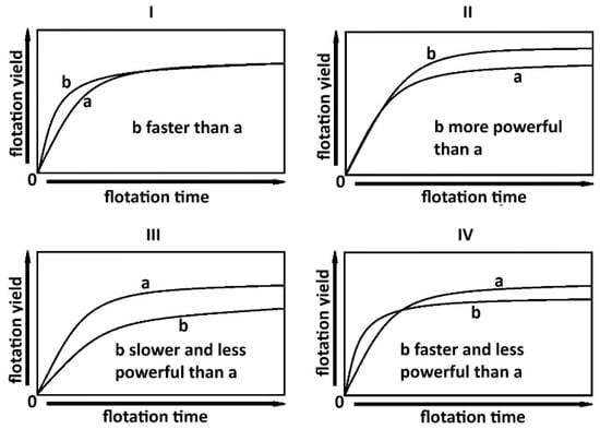
Figure 1.
An overview of flotation with different kinetics (faster or slower) and thermodynamics (more or less powerful), (I)—faster flotation, (II)—more powerful flotation, (III)—slower and less powerful flotation, (IV)—faster and less powerful flotation [7].
The aim of this paper was to compare the flotation kinetics of copper shale in the presence of α-terpineol (C10H18O) with the flotation kinetics in the presence of NaCl at increasing concentration of both reagents. α-terpineol was used as a typical frother applied in laboratory tests. The choice of NaCl results was made from the fact that this salt is frequently present in industrial flotation environments. It should be added that the mechanisms of action in the flotation of both applied surface active agents are different. Most salts, including NaCl, improve flotation due to their partial dehydration of the hydrophobic particle surface [6,29,30], while surfactants make the thin layers between particle and gas bubble less stable [31,32]. However, too high a frother concentration reduces flotation due to the significant decrease in the surface tension of the aqueous solution and the resulting decrease in the contact angle being a measure of hydrophobicity, known as the Zisman effect [33,34].
2. Materials and Methods
The copper-bearing shale samples used in this study were obtained from the Mineral Processing Laboratory (LPK) of the Faculty of Geoengineering, Mining and Geology, Wrocław University of Science and Technology, under inventory number CAS 386, Copper Shale B. The material was characterized by 2.9% Cu, 7.3% organic carbon, and 15.1% CO2 contents.
The shale samples were first crushed using a jaw crusher, then ground in a drum mill. A grain fraction smaller than 0.125 mm was separated using sieves. This fraction served as the feed for flotation tests, with a sample mass of 30 g per test. Flotation was conducted in a laboratory Mechanobr flotation machine with a 0.3 dm3 flotation cell and an air flow rate of 40–45 dm3/h [35].
Fractional flotation tests of copper shale were performed in the presence of NaCl and α-terpineol and also without any reagents. The flotation duration was 20 min, and four successive concentrates (K) were used. The tailings (O) were the remaining materials after flotation (Figure 2).
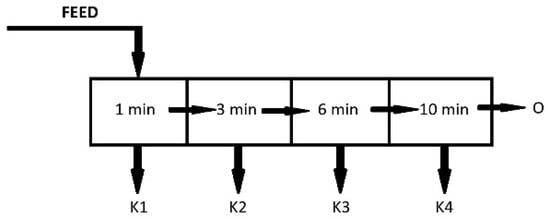
Figure 2.
A schematic diagram of the conducted kinetic flotation tests.
Table 1 presents the flotation conditions, along with the applied doses of NaCl and C10H18O as frothers.

Table 1.
The flotation test conditions for copper-bearing shale. F8—data from Kowalczewska and Ratajczak [36].
After flotation, the products were rinsed with water and filtered using a Büchner funnel, then dried in a laboratory oven at 105 °C for 24 h. After drying, the products were weighed, and their flotation yields were determined.
3. Results and Discussion
3.1. Copper-Bearing Shale Flotation
Figure 3 presents the relationship between cumulative shale recovery (R = R(t)) and flotation time (t) for the systems listed in Table 1. It can be observed that the flotation carried out without reagents (F1) results in a very slow increase in shale recovery, representing the lowest final (ultimate) recovery among all tests. The curve flattens over time as it approaches ultimate recovery R∞. During this flotation, virtually no froth is observed, and only the most hydrophobic and lightest particles were carried to the water surface, forming a thin film. Most of the recovery very likely caused by the mechanical carryover of particles [9].
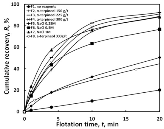
Figure 3.
The flotation kinetics of copper-bearing shale in water and in the presence of NaCl and α-terpineol. F8—data from [36].
Flotation with α-terpineol was noticeably more effective than flotation without reagents. The tests with α-terpineol yielded high final recoveries because relatively high (150, 225, and 300 g/t) doses of frother were applied. An even higher frother concentration (333 g/t) can reduce the flotation outcome, as was observed elsewhere [37,38,39]. The data for that flotation come from Kowalczewska and Ratajczak [36].
Salt-based flotations displayed a more dynamic flotation course compared to those without reagents. Increasing the concentration of salt improved flotation. Among the salt-based tests, flotation at 1 mol/dm3 NaCl (F7) achieved the best R∞. It was only slightly less effective than flotation with α-terpineol (from of 150 to 300 g/t) in terms of final recovery.
3.2. Fitting of Copper-Bearing Shale Flotation with First-Order Kinetics
The flotation kinetics of copper-bearing shale, as shown in Figure 3, were approximated with Equation (2), that is, the kinetics of the first order. Table 2. presents the key indicators used to describe flotation kinetics, where R∞ is the ultimate recovery (%), n is the kinetic order, and k is the flotation rate constant (1/min). The values of the statistical determination coefficient from 0.976 to 0.999 indicate that the kinetics of the first order is very suitable for the approximation of the obtained experimental data.
Table 2.
The kinetic parameters of copper-bearing shale flotation. F8—data from [36].
3.3. The Relationship Between Ultimate Recovery and the Flotation Rate Constant for Copper-Bearing Shale
Figure 4 shows the flotation results for copper shale, illustrating the relationship between ultimate recovery (R∞) and the first-order flotation rate constant (k).
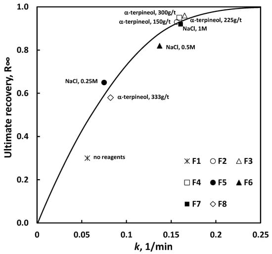
Figure 4.
The relationship between (R∞) and k for copper shale flotation kinetics with the kinetic order n = 1. F1–F7, this work; F8, data from [36].
It results from Figure 4 show that the character of the relationship between ultimate recovery and the first-order flotation rate constant (k) is similar for both α-terpineol and NaCl, even though the mechanism of their action of flotation is different. According to the literature data, most salts, including NaCl, improve flotation due to their partial dehydration of the hydrophobic particle surface [6,29,30]. On the other hand, small concentrations of surfactants improve flotation by reducing the stability of the thin layers between particles and gas bubbles [31,32], while high concentrations make flotation worse due to the significant decrease in the surface tension of the flotation solution, leading to a drop in the particle-water-air system hydrophobicity [33,34]. As can be seen in Figure 4. comparable flotation results for NaCl and α-terpineol are obtained at different concentrations of the reagents. The flotation in pure water is slightly off the approximation line due to some mechanical carryover of the shale particles.
4. Conclusions
Usually, there is mostly mechanical carryover of hydrophobic particles during the flotation test in pure water. An addition of surface active reagents to a flotation system induces the flotation of the particles. However, the degree of flotation change depends on the concentration of the applied reagent, as well as the mechanism of interactions between the particle, the gas bubble and the aqueous phase. It appears from this study that the relationship between the first-order flotation rate constant and the ultimate recovery of the investigated shale sample follows the same pattern, both for α-terpineol (surfactant) and NaCl (salt), despite their different mechanisms of action. In addition to that, at a very high concentration of NaCl, there is a change in the mechanism of gas bubble attachment, but the pattern of the R∞ = f(k) relationship remains the same. These findings require further verification for other flotation systems.
Our future research will deal with additional flotation tests to refine the found correlation between ultimate recovery and flotation kinetics, taking into account the applied dose of frother and salt, and to find mathematical relationships between these parameters. It should allow the practical utilization of the obtained correlations for flotation optimization by plant operators for processing copper-bearing shale when there are variations in the chemistry of the plant water.
Author Contributions
Conceptualization, T.A.R.; methodology, T.A.R. and W.N.; investigation, W.N. and T.A.R.; resources, T.A.R.; writing—original draft preparation, W.N.; writing—review and editing, W.N. and T.A.R.; supervision, T.A.R.; funding acquisition, T.A.R. All authors have read and agreed to the published version of the manuscript.
Funding
This research has received funding from the state science budget in 2025 (B_RPB_BAD_EXP_BAM–8253050501).
Data Availability Statement
Data are contained within this article.
Conflicts of Interest
The authors declare no conflicts of interest.
References
- Arbiter, N.; Harris, C.C. Flotation kinetics. In Froth Flotation: 50th Anniversary Volume; Fuerstenau, D., Ed.; American Institute of Mining, Metallurgical and Petroleum Engineers: New York, NY, USA, 1962. [Google Scholar]
- Laskowski, J. Coal flotation in solution with a raised concentration of inorganic salts. J. Colliery Guard. 1965, 211, 361–366. [Google Scholar]
- Laskowski, J.; Iskra, J. Role of capillary effect in bubble particie collision in flotation. Trans. Inst. Min. Metall. 1970, 79, C6–C10. [Google Scholar]
- Laskowski, J. The relationship between flotability and hydrophobicity. In Advances in Mineral Proccesing; Somasundaran, P., Ed.; Society of Mining Engineers, Inc.: Littleton, CO, USA, 1986; pp. 189–208. [Google Scholar]
- Li, C.; Somasundaran, P. Role of electrical double layerforces and hydrophobicity in coal flotation in NaCl solutions. Energy Fuels 1993, 7, 244–248. [Google Scholar] [CrossRef]
- Laskowski, J. Coal flotation and fine coal utilization. In Developments in Mineral Processing, 14th ed.; Fuerstenau, D.W., Ed.; Elsevier: London, UK, 2001. [Google Scholar]
- Ratajczak, T.; Drzymała, J. Flotacja Solna; Oficyna Wydawnicza Politechniki Wrocławskiej: Wrocław, Poland, 2003. (In Polish) [Google Scholar]
- Wills, B.; Napier Munn, T. Wills’ Mineral Processing Technology. An Introduction to the Practical Aspects of Ore Treatment and Mineral Recovery, 7th ed.; Butterworth-Heinemann: London, UK, 2006. [Google Scholar]
- Drzymala, J. Mineral Processing. Foundations of Theory and Practice of Minerallurgy; Oficyna Wydawnicza Politechniki Wrocławskiej: Wrocław, Poland, 2007; pp. 381–382. [Google Scholar]
- Laskowski, J.; Castro, S. Flotation in concentrated electrolyte solutions. Int. J. Miner. Process. 2015, 144, 50–55. [Google Scholar] [CrossRef]
- Merta, P.; Drzymała, J. Wpływ chlorku sody i octanu sodu na flotację solną węgla antracytowego jako modelu substancji bogatych w kerogen. In Łupek Miedzionośny II; Kowalczuk, P.B., Drzymała, J., Eds.; WGGG PWr: Wrocław, Poland, 2016; pp. 195–200. (In Polish) [Google Scholar]
- Kuklińska, M.; Ratajczak, T. Flotacja łupka miedzionośnego w wodnych roztworach soli. In Łupek Miedzionośny II; Kowalczuk, P.B., Drzymała, J., Eds.; WGGG PWr: Wrocław, Poland, 2016; pp. 184–187. (In Polish) [Google Scholar]
- Feng, Q.; Zhang, Y.; Zhang, G.; Han, G.; Zhao, W. A novel sulfidization system for enhancing hemimorphite flotation through Cu/Pb binary metal ions. Int. J. Min. Sci. Technol. 2024, 34, 1741–1752. [Google Scholar] [CrossRef]
- Shen, Z.-H.; Wen, S.-M.; Hao, J.-M.; Feng, Q.-C. Flotation separation of chalcopyrite from pyrite using mineral fulvic acid as selective depressant under weakly alkaline conditions. Trans. Nonferrous Met. Soc. China 2025, 35, 313–325. [Google Scholar] [CrossRef]
- Konopacka, Ż.; Zagożdżon, K.D. Łupek miedzionośny legnicko-głogowskiego okręgu miedziowego. In w: Łupek Miedzionośny; Drzymała, J., Kowalczuk, P.B., Eds.; WGGG PWr: Wrocław, Poland, 2014; pp. 7–12. (In Polish) [Google Scholar]
- Pawlos, W.; Poznar, E.; Krzemińska, M. Wpływ litologicznego zróżnicowania nadawy na wskaźniki technologiczne w zakładach wzbogacania rud KGHM Polska Miedź SA. Biul. Państwowego Inst. Geol. 2017, 469, 67–74. (In Polish) [Google Scholar] [CrossRef]
- Konstantynowicz-Zielińska, J. Petrografia i geneza łupków miedzionośnych monokliny przedsudeckiej. Rudy Met. Nieżelazne 1990, 35, 128–133. (In Polish) [Google Scholar]
- Wyżykowski, J. Cechsztyńska formacja miedzionośna w Polsce. Przegląd Geol. 1971, 19, 117. (In Polish) [Google Scholar]
- Cox, D.P.; Lindsey, D.A.; Singer, D.A.; Moring, B.C.; Diggles, M.F. Sediment-Hosted Copper Deposits of the World: Deposit Models and Database. Open-File Report 03-107, Version 1.3. 2003, Revised 2007. Available online: http://pubs.usgs.gov/of/2003/of03-107 (accessed on 24 June 2025).
- Fuerstenau, M.C.; Jameson, G.J.; Yoon, R.H. (Eds.) Froth Flotation: A Century of Innovation; Society for Mining, Metallurgy, and Exploration, Inc.: Littleton, CO, USA, 2007; pp. 2007–2891. [Google Scholar]
- Bakalarz, A. Charakterystyka chemiczna i mineralogiczna wybranych łupków pochodzących z Legnicko-Głogowskiego okręgu miedziowego. In w: Łupek miedzionośny; Drzymała, J., Kowalczuk, P.B., Eds.; WGGG PWr: Wrocław, Poland, 2014; pp. 13–18. (In Polish) [Google Scholar]
- Bu, X.; Xie, G.; Chen, Y.; Ni, C. The order of kinetic models in coal fines flotation. Int. J. Coal Prep. Util. 2017, 37, 113–123. [Google Scholar] [CrossRef]
- Bu, X.; Xie, G.; Peng, Y.; Ge, L.; Ni, C. Kinetics of flotation. Order of process, rate constant distribution and ultimate recovery. Physicochem. Probl. Miner. Process. 2017, 53, 342–365. [Google Scholar]
- Brożek, M.; Młynarczykowska, A. Analysis of kinetics models of batch flotation. Physicochem. Probl. Miner. Process. 2007, 41, 51–65. [Google Scholar]
- Brożek, M.; Młynarczykowska, A. Kinetyka Flotacji; Wydawnictwo Instytutu Gospodarki Surowcami Mineralnymi i Energią PAN: Kraków, Poland, 2009. (In Polish) [Google Scholar]
- Zuniga, H.G. Flotation recovery is an exponential function of its rate. Boletín Soc. Nac. Min. Santiago Chile 1935, 47, 83–86. [Google Scholar]
- Drzymała, J.; Ratajczak, T.; Kowalczuk, P.B. Kinetic separation curves based on process rate considerations. Physicochem. Probl. Miner. Process. 2017, 3, 983–995. [Google Scholar] [CrossRef]
- Gharai, M.; Venugopal, R. Modeling of flotation process—An overview of different approaches. Miner. Process. Extr. Metall. Rev. 2016, 37, 120–133. [Google Scholar] [CrossRef]
- Laskowski, J. Coal surface chemistry and its role in fine coal beneficiation and utilization. Coal Prep. 1994, 14, 115–132. [Google Scholar] [CrossRef]
- Laskowski, J. Coal surface chemistry and its effect on fine coal processing. In High Efficiency Coal Preparation: An International Symposium; Kawatra, S.K., Ed.; SME: Littleton, CO, USA, 1995; Volume 14, pp. 163–175. [Google Scholar]
- Kosior, D.; Zawala, J.; Malysa, K. When and how α-terpineol and n-octanol can inhibit the bubble attachment to hydrophobic surfaces. Physicochem. Probl. Miner. Process. 2011, 47, 169–182. [Google Scholar]
- Kruszelnicki, M.; Kowalczuk, P.B.; Polowczyk, I. Three-phase contact formation between an air bubble and solid surfaces with different hydrophobicity degrees in liquid. Colloids Surf. A Physicochem. Eng. Asp. 2023, 676, 132067. [Google Scholar] [CrossRef]
- Zisman, W.A. Relation of the Equilibrium Contact Angle to Liquid and Solid Constitution. In Contact Angle, Wettability, and Adhesion; Advances in Chemistry Series; ACS Publications: Washington, DC, USA, 1964; Volume 43, pp. 1–55. [Google Scholar]
- Lyklema, J. Fundamentals of Interface and Colloid Science. Vol. III, Liquid-Liquid Interfaces; Academic Press: London, UK, 2000. [Google Scholar]
- Nowak, W. Określenie i Analiza Stałej Prędkości Flotacji Łupka Miedzionośnego w Funkcji Zmiennego Stężenia Spieniacza. Engineering Thesis, Wydział Geoinżynierii, Górnictwa i Geologii, Politechnika Wrocławska, Wrocław, Poland, 2025. (In Polish). [Google Scholar]
- Kowalczewska, K.; Ratajczak, T. Flotacja łupka miedzionośnego w szerokim zakresie stężenia spieniacza. In Łupek Miedzionośny; Ratajczak, T.V., Ed.; WGGG PWr: Wrocław, Poland, 2021; pp. 103–107. (In Polish) [Google Scholar]
- Kowalczuk, P.B.; Mroczko, D.; Drzymala, J. Influence of frother type and dose on collectorless flotation of copper-bearing shale in a flotation column. Physicochem. Probl. Miner. Process. 2015, 51, 547–558. [Google Scholar]
- Kowalczuk, P.B.; Zawala, J.; Kosior, D.; Drzymala, J.; Malysa, K. Three-phase contact formation and flotation of highly hydrophobic polytetrafluoroethylene in the presence of increased dose of frothers. Ind. Eng. Chem. Res. 2016, 55, 839–843. [Google Scholar] [CrossRef]
- Drzymala, J.; Kowalczuk, P.B. Classification of Flotation Frothers. Minerals 2018, 8, 53. [Google Scholar] [CrossRef]
Disclaimer/Publisher’s Note: The statements, opinions and data contained in all publications are solely those of the individual author(s) and contributor(s) and not of MDPI and/or the editor(s). MDPI and/or the editor(s) disclaim responsibility for any injury to people or property resulting from any ideas, methods, instructions or products referred to in the content. |
© 2025 by the authors. Licensee MDPI, Basel, Switzerland. This article is an open access article distributed under the terms and conditions of the Creative Commons Attribution (CC BY) license (https://creativecommons.org/licenses/by/4.0/).