1. Introduction
In recent years, tailings surface disposal and underground cemented paste backfill (CPB) goafs have become extensive risk sources for mine safety and environmental protection [
1,
2]. The conventional low-concentration tailings treatment approach has a higher potential for causing land pollution and dam failure [
3]. Paste and thickened tailing (PTT) technology is a pollution-free environmental protection technology with high emission concentrations. Before discharge, most processing water is recovered from tailings slurry recycling to plants, which can improve the utilization rate of water resources, reduce heavy metal ion pollution [
4] and improve dam safety.
The surface subsidence risk after mining can be reduced by pumping the PTT underground as CPB materials [
5,
6,
7]. Tailings are generally used as fine aggregates in CPB materials to support the goaf surrounding rock. The tailings slurry from plants contains a large number of fine particles and mineral processing wastewater. Mature fine particles hardly settle in suspensions to form a high-concentration underflow in the gravity thickening process [
8,
9].
The gravity solid–liquid separation process can increase the solid concentration of the slurry and reduce the liquid content [
10]. Tailings dewatering research has received increasing attention; various polymer assisted flocculation dewatering methods have been widely used in tailings settlement [
11,
12]. Peng [
13] and Lu et al. [
14] found that the combination of high-molecular weight anionic and low molecular weight cationic polymers can improve the settling rate of tailings; Arjmand et al. [
15] improved the flocculation and dewatering performance of tailings based on the solution pH and flocculant dosage; Liu et al. [
16] studied a custom high-solidification water additive in terms of the dewatering rate to improve the early compressive strength of CPB materials; Yang [
17] and Dwari et al. [
18] studied the effect of flocculants on the settlement behaviour and flocculation consolidation characteristics of tailings.
The shearing induced by rotating rakes plays an important role in improving the underflow concentration. The flocculant is a common way to capture fine particles to form large-scale aggregates that seal a large amount of water inside the aggregates [
19,
20,
21]. The popular device for PTT production is the deep-cone thickener or deep-bed thickener from different manufacturers. Melbourne University and the CSIRO Center in Australia have published outstanding results on the theoretical model of thickeners in the continuous state [
22,
23,
24]. Erichöfgen et al. [
25] developed a high-pressure dehydration roller (HPDR) to improve the degree of dehydration of materials by applying high pressure and induced shear; Sharna et al. [
26] studied the dewatering efficiency of the double-polymer flocculation system for materials; Qi et al. [
27] proposed a novel hybrid machine learning method to predict the flocculation dewatering performance considering shearing effects; Jiao et al. [
28] studied the influence of the micro-pore structure of the flocs in tailings beds on the target underflow concentration. The honeycomb structure and network formed by flocculated tailings aggregates pose a challenge to the dewatering performance.
The dewatering process of flocculated aggregate networks has received much attention for improving the underflow density. With the development of non-destructive testing and image processing technology, computed tomography (CT) scanning technology has been widely used in mining and geotechnical engineering research [
29,
30,
31]. The thickening process of unclassified tailings entails the densification of the floc structure. The tailings position and pore structure can be observed from the micro-perspective [
32]. Philip et al. [
33] studied the modification of the network structure of flocculated tailings under shearing and examined the consolidation and compactness of the sediment bed. Malíková et al. [
34] carried out industrial innovations on the tailings dewatering process based on the interactions between colloidal particles at different temperatures and mixing conditions. To date, CT technology has become the best way to reveal the mechanism of micro-scale precipitation.
Flocculation and dewatering tests were conducted with a self-developed pilot scale continuous thickener combined with CT scanning technology. After flocculated tailings settlement, water was sealed in the sedimentary bed between the flocculated flocs. In this device, the rakes and pickets rotate to roll up the particles in the bed, break the static balance between the particles and water, connect the pores, discharge the sealed water, and form a high-concentration underflow. The characteristics of the concentration and porosity of the tailings bed with/without shear were obtained three-dimensional reconstruction from CT images. The micro-pore structure and distribution of the pore number and shape are identified from the 3D model. The water channel evolution characteristics of the shear bed under flocculation and sedimentation are studied to reveal the shearing dewatering mechanism.
2. Materials and Method
2.1. Tailings and Flocculants
Unclassified flotation tailings are obtained from a vanadium processing plant in an iron mine. The tailings pH is neutral to alkaline, with a low bulk density and high porosity. The specific gravity of the tailings is 2.966 t/m
3, and the bulk density is 1.438 t/m
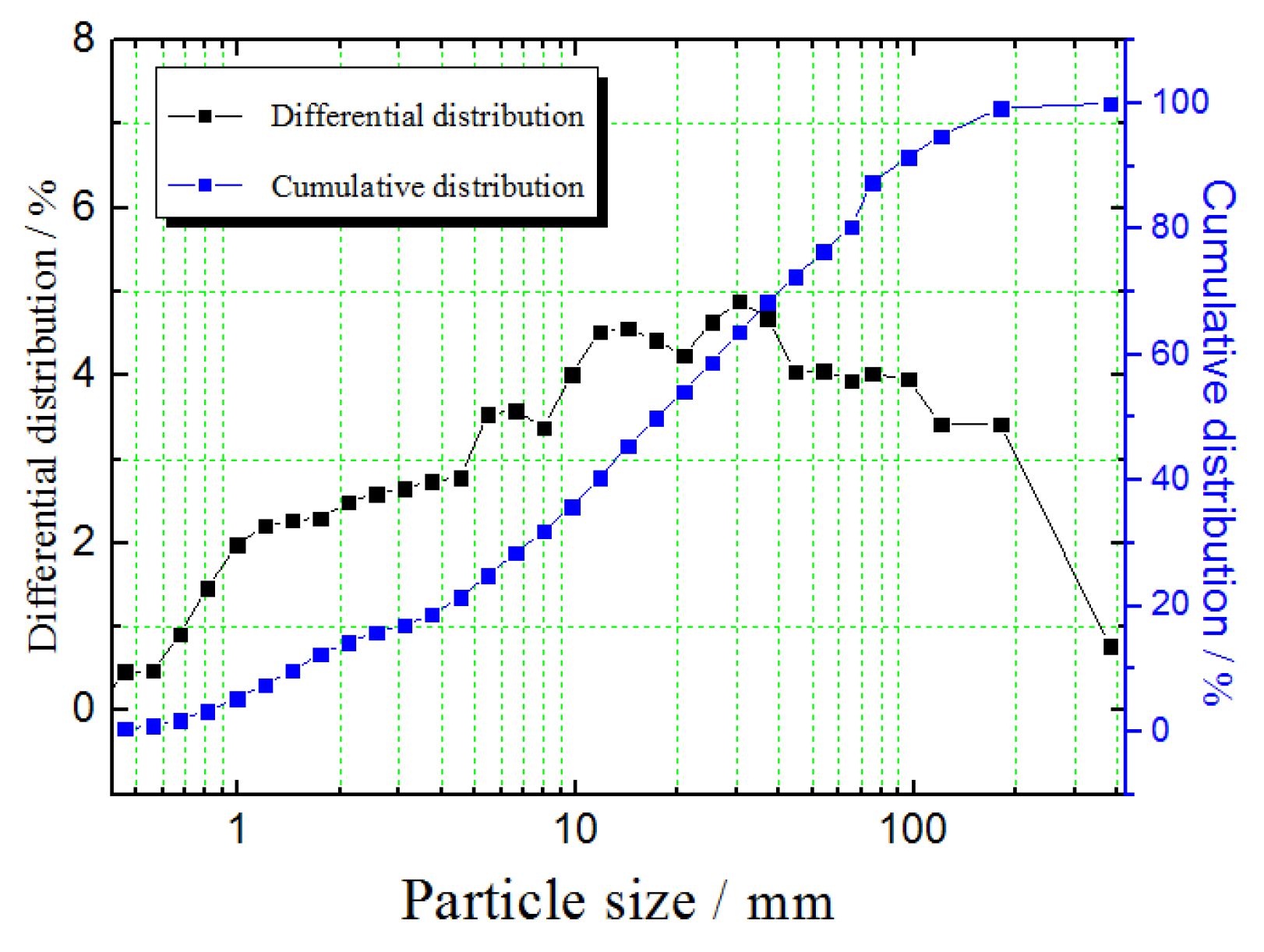
3. The tailings particle size distribution is shown in
Figure 1. With D
50 = 17.20 μm, D
10 = 1.56 μm, D
90 = 94.34 μm, the particles smaller than 74 μm account for 87.4% of the total weight, and the particles finer than 37 μm account for 68.36% of the total weight.
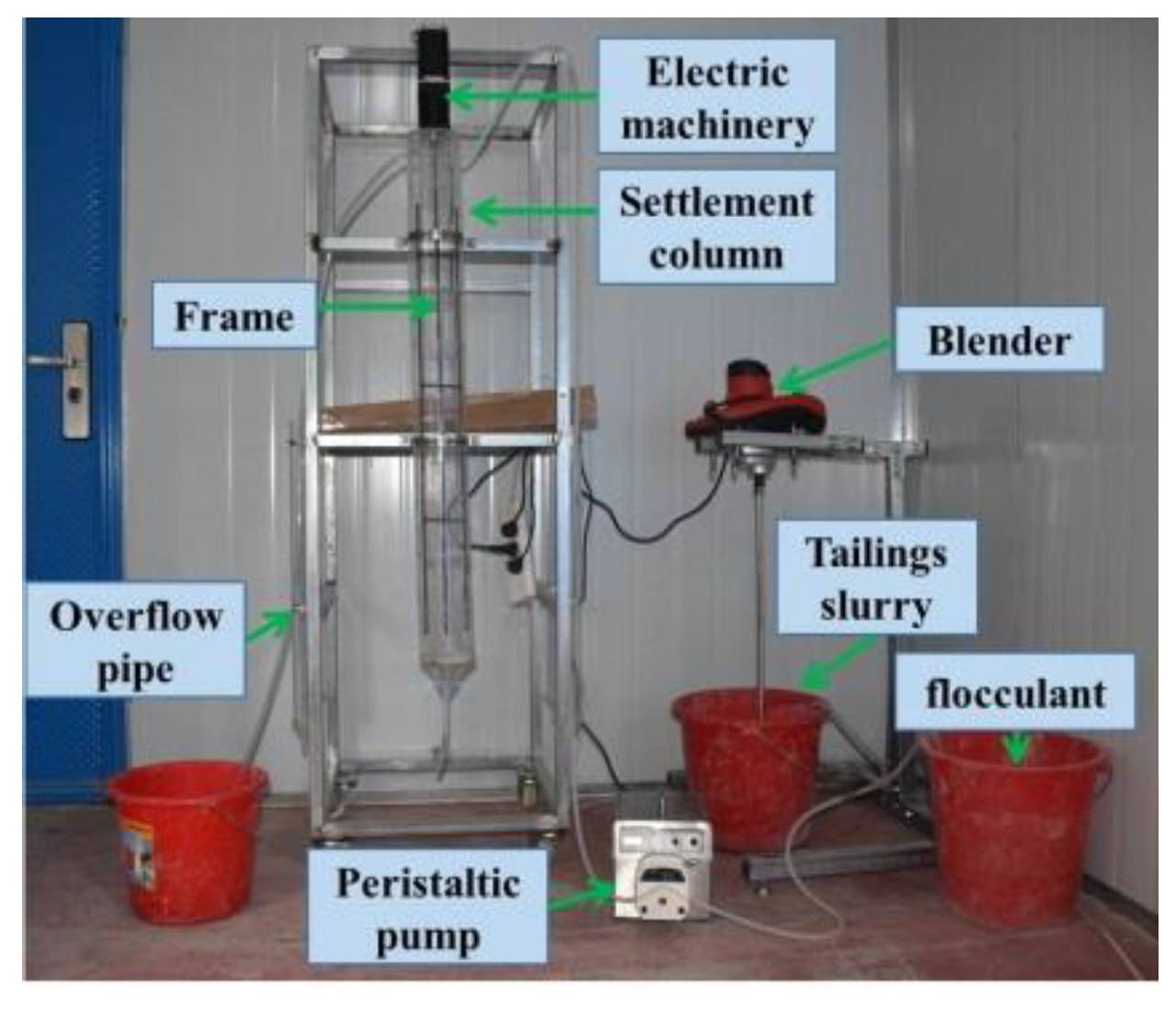
The settlement cylinder is 10 cm in diameter and 50 cm in height, with a four-picket rake. The rake rotation speed is adjustable, and the rake torque can be detected by sensors to simulate the thickener operations. The test platform is shown in
Figure 2.
The experimental parameters are as follows: The flocculant is a 20 million molecular weight XJTH Xinjiang anionic polyacrylamide (PAM), the dosage is 30 g per ton of solids, the concentration of the flocculant solution is 0.01 wt %, and the concentration of the feed slurry is 10 wt %.
2.2. CT Scanning Tests
The development of X-ray CT provides an alternative method for obtaining pore geometry parameters. In this study, a multifunctional high-resolution system, Phoenix V, General Electric, was adopted. Adopting the in situ sampling method, the bottom 10 cm of the bed of the cylindrical settlement column was sampled. When the target underflow concentration, bed height, dwell time and other requirements are met in the experiments, the settling column and mixing rake frame are disassembled. The supernatant is discharged to expose the detection bed layer as the target. After removing the wall of the settling column, a thin plastic plate is inserted at the lower part of the sample column, and the upper part is covered with a thin plastic plate. The plastic plate and sampling pipe are fixed and connected with a quick-drying adhesive, and both sides and their sleeve are pressed into a fixed plastic bag. The prepared dry sample is placed directly in the CT machine. The sample should not be disturbed to avoid damaging the particle structure. The magnification is 1000 times, and the resolution of the scanning unit is 5 μm. The scanning length is 100 mm [
35].
2.3. Three Dimensional Reconstruction
The pore size distribution (PSD) is widely used in pore morphology research of porous media [
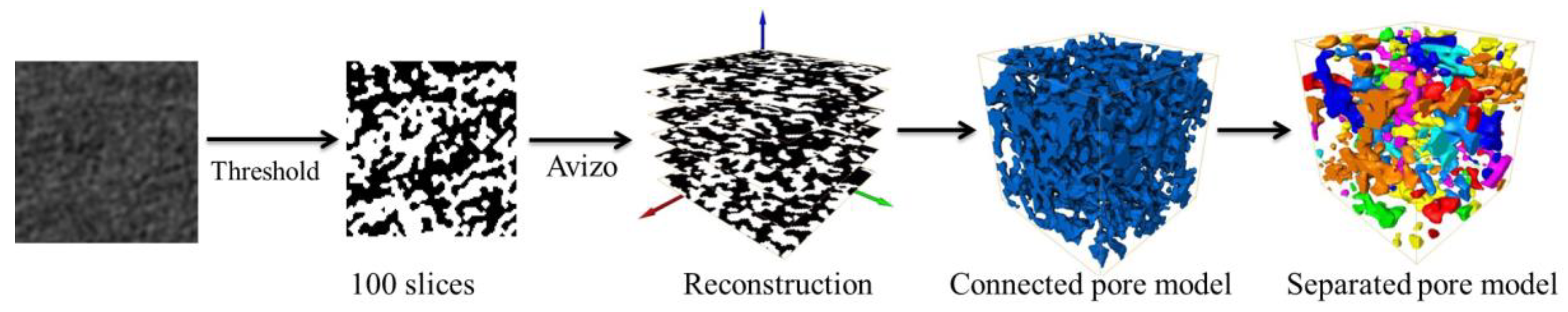
36]. The system noise in the original CT images needs to be filtered with ImageJ and Avizo software (Version: 2019.1), which can eliminate noise while maintaining the image details. The image binarization process divides a gray image into a target and background via an optimal threshold. In this study, the threshold of each image group is 121. Only black and white colours occur in the final binary image, where the black colour represents the pores, and the white colour represents the tailings material. These two-dimensional binary images are combined in a certain order to obtain the three-dimensional (3D) image of the tailings pores. Separated and connected pores can be extracted from the 3D reconstructed model. The reconstruction process and analysis method are shown in
Figure 3.
The pore microstructure was divided into pore and throat spaces through the maximum sphere search algorithm, and the various pore spaces are shown in different colours in
Figure 3.
2.4. Pore Separation Theory
The maximum sphere search algorithm assumes that the pixels contained in any two adjacent largest spheres will not completely coincide. The concept of the upper and lower radius limits is introduced [
37].
R2LEFT represents the square of the lower radius limit, and
R2RIGHT represents the square of the upper limit, while
R2LEFT <
R2 <
R2RIGHT applies.
where
S is the pore space,
Sg are the skeleton particles,
R2RIGHT is the distance between the ball centre C(
xc,yc,zc) and flocculent chain
Vg(xg,yg,zg) closest to the ball centre,
R2LEFT is the distance between the ball centre and the farthest pixel from the ball centre within the ball radius of
RRIGHT, and
V(
x,y,z) is the pore voxel farthest from the ball center within the radius of
RRIGHT.
3. Results
3.1. The Continuous Thickening Tests
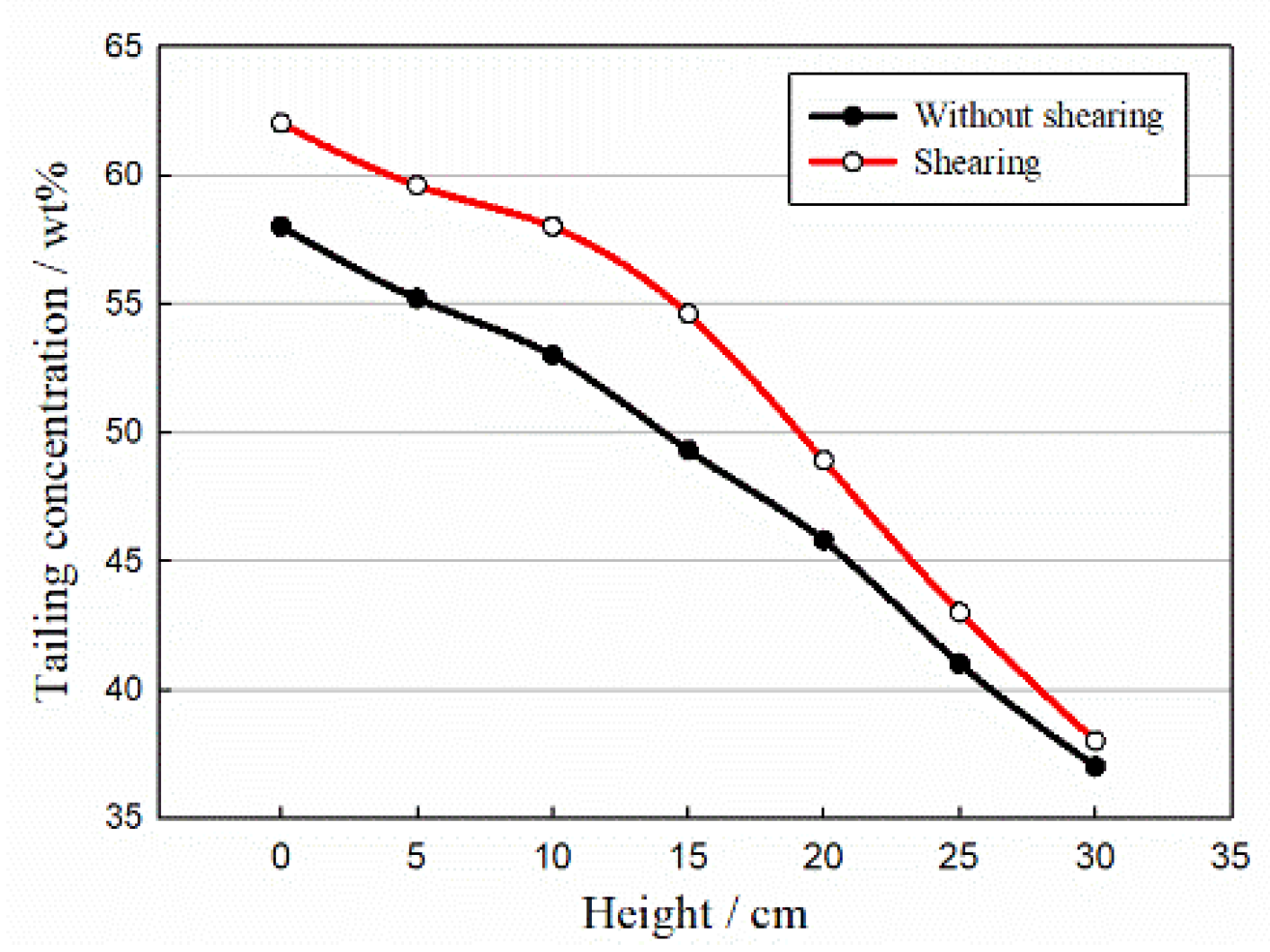
The target underflow concentration, residence time and bed height are recorded during the test. The tailings bed concentration distribution results are shown in
Figure 4.
In the continuous thickening tests, the concentration of the feed slurry is 10 wt %, the bed height is 30 cm, and the residence time is 34 min. The average concentration of the tailings bed without shear is 50.10 wt %, the underflow is 58 wt %, and the concentration of the top layer is 37 wt %. At a stirring speed of 2 r/min, the average concentration of the tailings is 55.82 wt %, the underflow concentration is 62 wt %, and the top layer concentration is 38 wt %. The average concentration of the tailings with shear is 11.42% higher than that of the tailings without shear.
The average porosities of the tailings compression bed without and with shear are 49.90 wt % and 44.18 wt %, respectively. The sheared bed porosity decreased 12.95%. The shearing effect is beneficial to the sealed-water drainage process.
3.2. Pore Extraction and Distribution
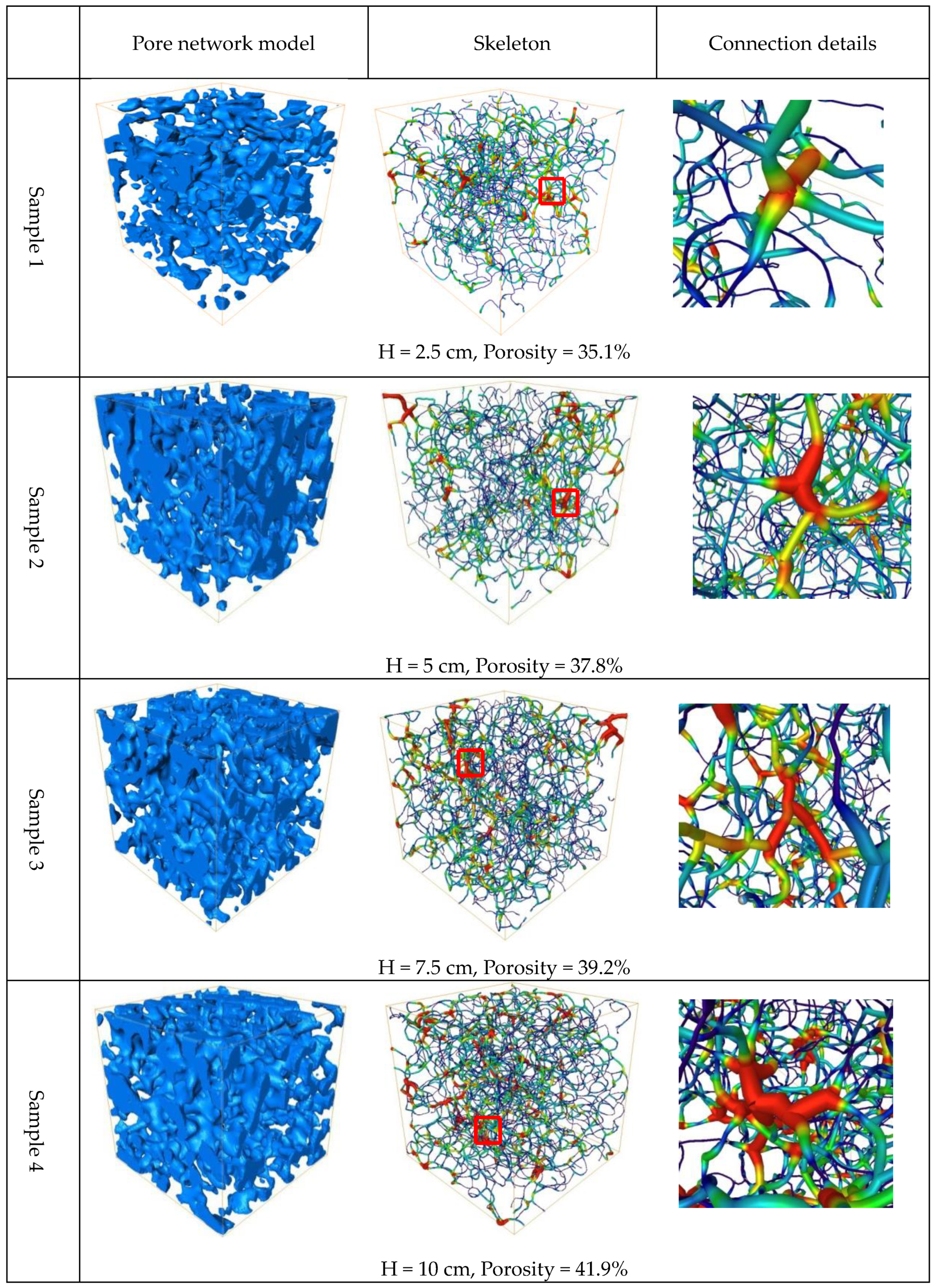
In the tailings bed, the pores between connected flocs form drainage flow channels. Cubic samples with 100-pixel side lengths were extracted from the 3D model at different heights to reveal the relationship between the bed height and porosity, as shown in
Figure 5.
Pore Distribution along the Bed Height
The slurry location in the tailings bed has a major influence on the pore morphology and connectivity. As shown in
Figure 5, four samples are detailed from a 10-cm tailings bed at heights of 2.5, 5, 7.5 and 10 cm. The blue cubic area in the left column represents the reconstructed pore network model, and the pore network skeleton is placed in the middle column, while the right column shows details of the connected pore skeleton.
The pores at the bottom of the tailings bed are compacted and consolidated but lack connectivity; most pores are independent and isolated from the network structure (Sample 1: height: 2.5 cm). In the middle of the bed (Sample 2: height: 5 cm), the pores, arranged in a flat network, are well connected, thus forming water flow channels. At the top of the bed (Samples 3 and 4), the flocs start to accumulate after free settling, and the large separation between the flocs establishes well-connected flow channels for water seepage. The porosity increases from 35.1 to 41.9 wt % within the bed from bottom to top.
The connectivity between pores can be obtained from the pore skeleton model. In the middle column of
Figure 5, the red joint tube-shaped area indicates multiple connected pores. The pores gradually expand according to a centralized trend, from an unconsolidated and isolated state to a centralized connected state with the bed height.
The connected nodes and areas in the pore skeleton model increase significantly from bottom to top of the bed. The formation of water flow channels depends on the distribution of connected pores. The pore skeleton details in the right column demonstrate the joint channels along the connecting nodes. The porosity increase is beneficial for the formation of node connections and more water flow channels [
38].
4. Discussion
4.1. Fractal Characteristics of the Pores
The fractal characteristics of the pores are calculated by the fractal box dimension [
39]. The fractal box dimension covers the fractal body with a square lattice, where is the side length of the square, and the minimum number of fractal bodies that can be covered with
NγB grids is calculated [
40]. Then the upper and lower fractal box dimensions of B are defined as:
DimB is the fractal box dimension of B. Its general form is:
where D is the fractal dimension and c is constant term. It is clear that
is linear with
.
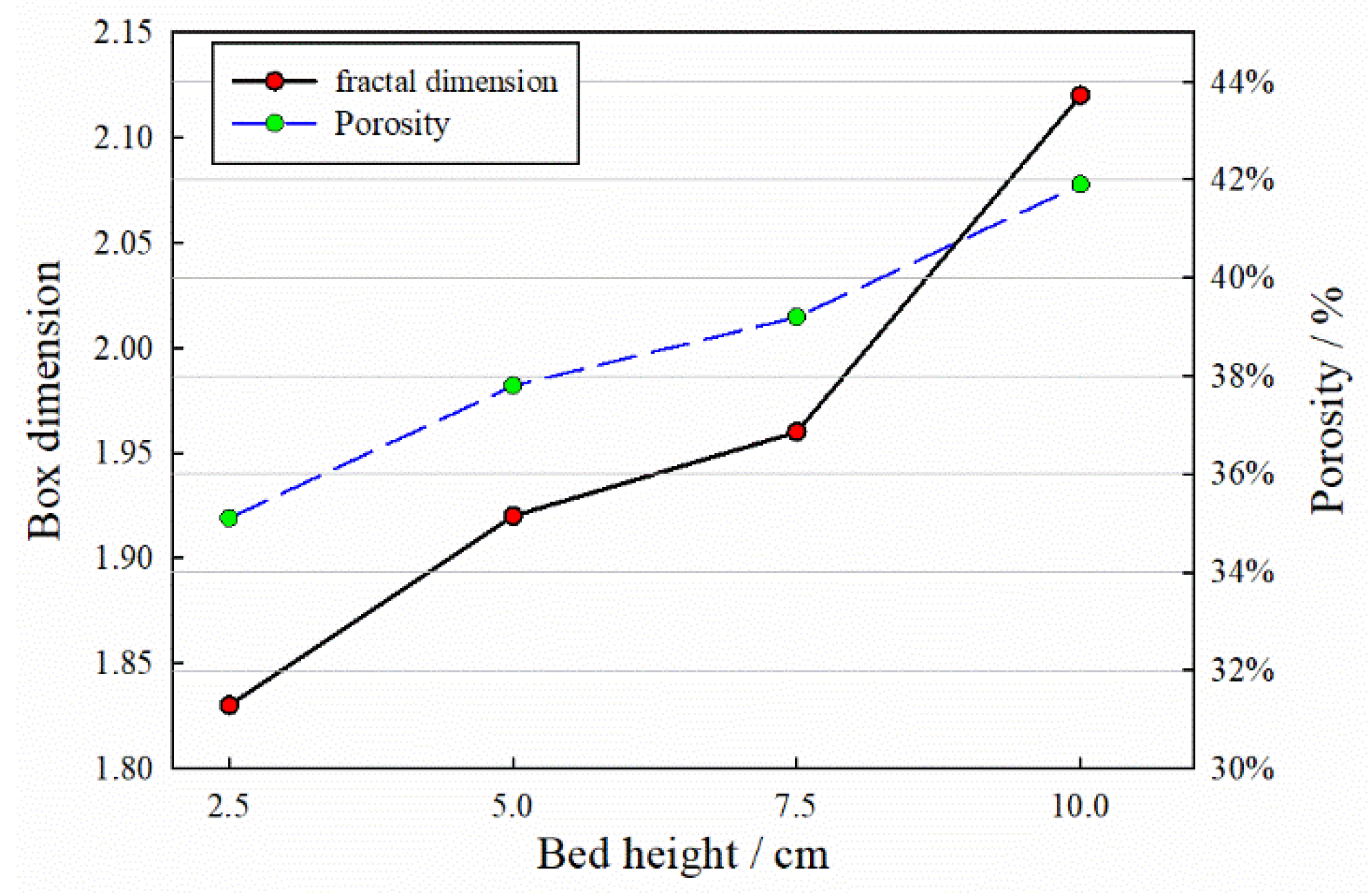
The pore structure of the tailings exhibits distinct fractal characteristics, as shown in
Figure 6. The box dimension results reveal that the box dimension of the pores at the bottom of the bed is low, ranging from 1.8 to 1.95; the fractal dimension gradually increases to 2.1 to 2.15 along the bed height. A high fractal dimension means a complex pore structure. The fractal parameters exhibit the same trend as the reconstructed porosity.
4.2. Pore Structure Separation Model
4.2.1. Pore Separation Model
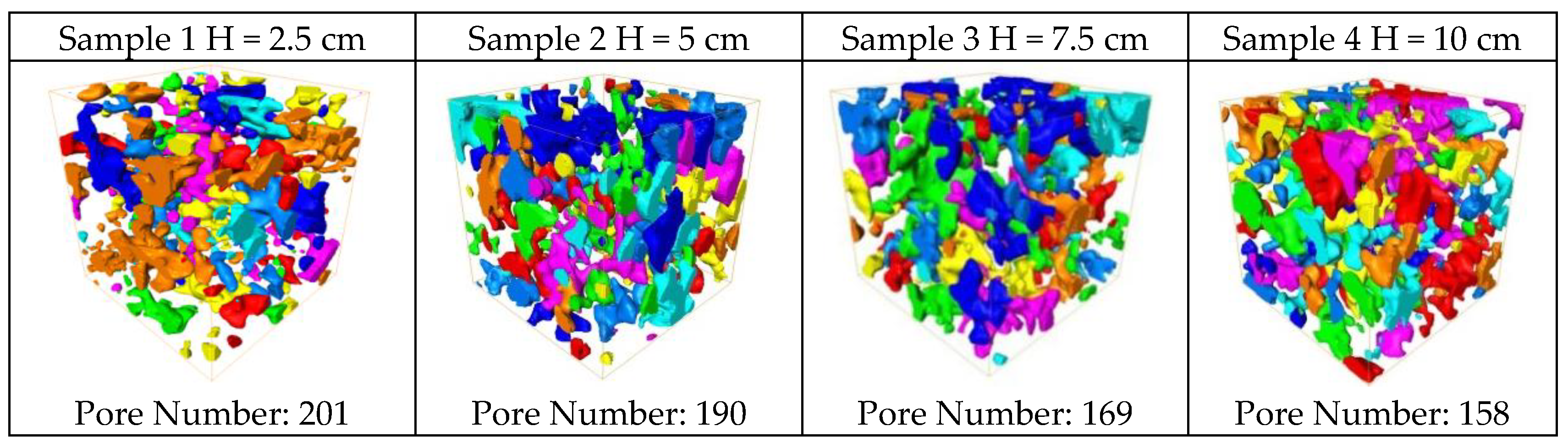
The pore separation model of the four location samples is shown in
Figure 7. [
41]. The various colours represent different pores by the maximum sphere search algorithm Pore structure parameters are extracted from the separated pore models.
The quantity of pores decreases with increasing bed height. As shown in
Figure 7, the pore quantity decreased 6.97%, 10.16% and 5.95%. The reduction occurs due to the poor connectivity between the pores at the bed bottom. The isolated pores sealed in water in the network structure. There are larger but fewer pores at the top of the bed, forming longer and large-diameter flow channels for sealed water-drainage.
4.2.2. Pore Volume Change
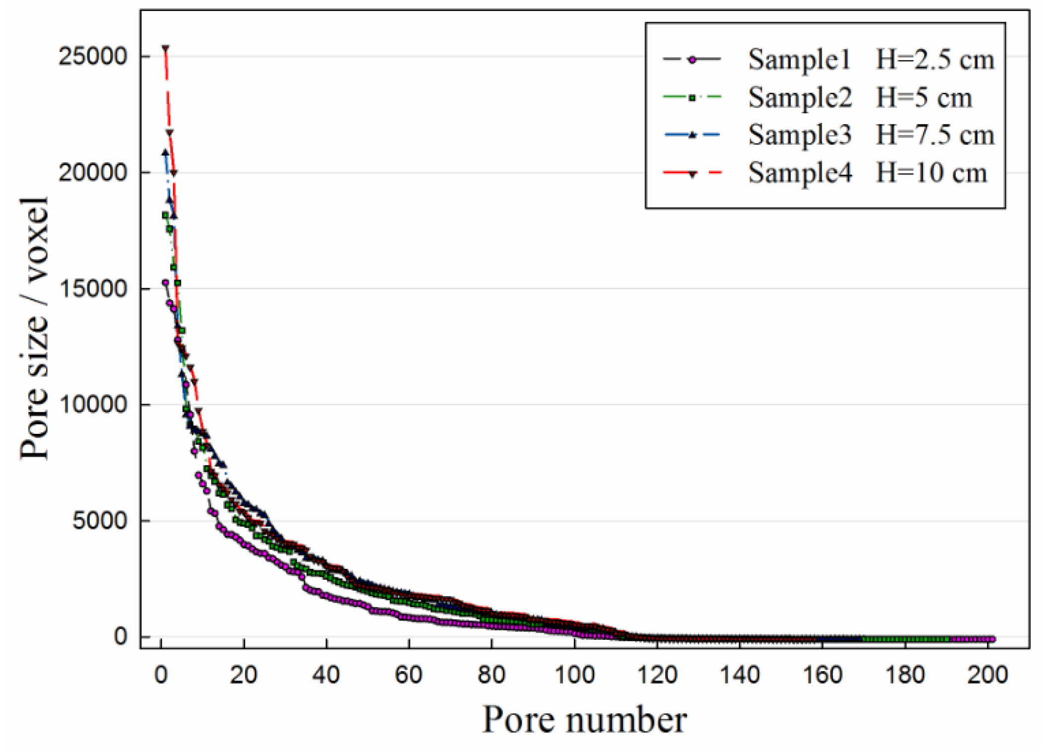
The pore volume distribution is extracted from the separated pore models, as shown in
Figure 8. According to the CT results, the pore reconstruction volume unit is the voxel, and 1 voxel = 125 μm
3. The average pore volume increases with the bed height. The maximum pore volumes at 2.5, 5, 7.5 and 10 cm along the bed height are 1.917 × 10
6, 2.155 × 10
6, 2.363 × 10
6 and 2.429 × 10
6 μm
3, respectively, successively increasing 12.42%, 9.26% and 2.97%; the average pore volumes are 2.183 × 10
5, 2.487 × 10
5, 2.899 × 10
5 and 3.249 × 10
5 μm
3, respectively, successively increasing 13.93%, 16.57% and 12.07%. The maximum pore volume exhibits a similar tendency as the average pore volume.
The pore volume evolution will affect the flow channel conductivity. A water flow channel is formed by a connected pore structure, which is the pathway of sealed-water drainage in the tailings bed. Large-scale pores are well connected, but there are certain quantities of small isolated pores in the bed, from which the sealed water can hardly be drained. The water retention capability of mature fine tailings is severely detrimental to the thickening process.
4.3. Pore Volume Distribution
The pore volume distribution in the compression tailings bed is shown in
Figure 9. The small-size pore quantity decreases, and the large-scale pore content increases with the bed height. At 2.5 cm in the bed (from the bed bottom), the number of pores smaller than 1.25 × 10
4 μm
3 (voxel = 100) accounts for 45.27% of the total number of pores. The pores larger than 2.5 × 10
5 μm
3 (voxel = 2000) account for 18.92% of the total pores. Correspondingly, at a height of 10 cm in the bed, the number of pores smaller than 1.25 × 10
4 μm
3 accounts for 23.42% of the total pores, and the number of pores larger than 2.5 × 10
5 μm
3 accounts for 36.06% of the total pores. The pore volume distributions are quite different. The tailings sedimentation state gradually changes from a dense state to a loose state.
Under shearing, the tailings flocs transition from the original loose arrangement state and become rearranged through gravity and mud pressure. In this process, the fine particles settlel into the macro-pores; the flocs will be deformed and compacted to form a high concentration underflow. The original macro-pores will be compressed, deformed and divided to form a large number of micro-pores, which will increase the pore quantity and reduce the total porosity. The water within the pores flows upward through the bed under shearing.
5. Conclusions
This work studied the micro-pore structure of tailings paste shear beds by continuous thickening and CT tests. The pore distribution and water flow channel evolution characteristics of the sheared bed under flocculation and sedimentation were revealed for underflow concentration improvement in the process of beneficial fine tailings gravity thickening.
(1) The porosity increased from 35.1 to 41.9 wt % from bottom to top in a 30-cm compression tailings bed. The porosity gradually increased in a consistent way to form a connected pore network, from a loose isolated state to a centralized connected state.
(2) The pore quantity in the tailings bed decreases with the bed height. The isolated pores at the bottom inhibit flow channel connectivity establishment, which seals water in the bed that cannot be readily discharged.
(3) The pore size and fractal dimension increase with the bed height. The average pore volume increased from 2.183 × 10⁵ to 3.249 × 105 μm3, and the fractal box dimension increased from the range 1.8~1.95 to the range 2.1~2.15 as the bed height increased from 2.5 to 10 cm. The sealed-water storage space increases with the pore shape complexity.
(4) After natural deposition, the water at the bottom of the bed is evenly distributed, the floc structure is relatively loose, the water connectivity between pores is good, and water forms a connected phase. The shear force produced by agitation disrupts the static balance between the floc structure and water, thus promoting the drainage of the water between the flocs; the flocs are destroyed under the shear force, the water inside the flocs is released, and the water in the water channels formed by the connected pores is discharged under the shear force and gravity.
(5) The mechanical shearing in the thickener destroys the original large pores into sub-level pores, reduces the bed porosity, releases the sealed water and enhances the underflow concentration. The pore quantity increases, and more isolated pores are formed with decreasing porosity. Rake shearing can notably increase the discharge rate of sealed water, which can improve the utilization and management of tailings.
Author Contributions
Conceptualization, X.C. and X.J.; methodology, H.J.; software, X.J.; validation, X.J., H.J. and J.L.; formal analysis X.J. and H.J.; investigation, Y.Y.; resources, H.J.; data curation, Y.Y.; writing—original draft preparation, X.C.; writing—review and editing, H.J.; visualization, X.J.; supervision, X.C.; project administration, J.L.; funding acquisition, H.J. All authors have read and agreed to the published version of the manuscript.
Funding
This work was funded by the National Natural Science Foundation of China Projects (51704094, 51834001), the Program for Science & Technology Innovation Talents in Universities of Henan Province (19HASTIT047), the Science and Technology Project of Henan Province (172102210286, 182102310012).
Conflicts of Interest
The authors declare no conflict of interest.
References
- Silva, M.M.V.G.; Lopes, S.P.; Gomes, E.C. Geochemistry and behavior of ree in stream sediments close to an old sn-w mine, ribeira, northeast portugal. Chem. Erde Geochem. 2014, 74, 545–555. [Google Scholar] [CrossRef]
- He, Y.; Li, B.; Zhang, K.; Li, Z.; Chen, Y.; Ye, W. Experimental and numerical study on heavy metal contaminant migration and retention behavior of engineered barrier in tailings pond. Environ. Pollut. 2019, 252, 1010–1018. [Google Scholar] [CrossRef] [PubMed]
- Zhao, H.; Gan, X.; Wang, J.; Tao, L.; Qin, W.; Qiu, G. Stepwise bioleaching of Cu-Zn mixed ores with comprehensive utilization of silver-bearing solid waste through a new technique process. Hydrometallurgy 2017, 171, 374–386. [Google Scholar] [CrossRef]
- Yang, L.; Wang, H.; Li, H.; Zhou, X. Effect of High Mixing Intensity on Rheological Properties of Cemented Paste Backfill. Minerals 2019, 9, 240. [Google Scholar] [CrossRef]
- Qi, C.; Tang, X.; Dong, X.; Chen, Q.; Fourie, A.; Liu, E. Towards Intelligent Mining for Backfill: A genetic programming-based method for strength forecasting of cemented paste backfill. Miner. Eng. 2019, 133, 69–79. [Google Scholar] [CrossRef]
- Chen, Q.; Zhang, Q.; Qi, C.; Fourie, A.; Xiao, C. Recycling phosphogypsum and construction demolition waste for cemented paste backfill and its environmental impact. J. Clean. Prod. 2018, 186, 418–429. [Google Scholar] [CrossRef]
- Lu, X.; Zhou, W.; Ding, X.; Shi, X.; Luan, B.; Li, M. Ensemble learning regression for estimating unconfined compressive strength of cemented paste backfill. IEEE Access 2019, 7, 72125–72133. [Google Scholar] [CrossRef]
- Zhao, H.; Zhang, Y.; Zhang, X.; Qian, L.; Sun, M.; Yang, Y.; Qiu, G. The dissolution and passivation mechanism of chalcopyrite in bioleaching: An overview. Miner. Eng. 2019, 136, 140–154. [Google Scholar] [CrossRef]
- Sun, Q.; Tian, S.; Sun, Q.; Li, B.; Cai, C.; Xia, Y.; Mu, Q. Preparation and microstructure of fly ash geopolymer paste backfill material. J. Clean. Prod. 2019, 225, 376–390. [Google Scholar] [CrossRef]
- Jiao, H.; Wang, S.; Wu, A.; Shen, H.; Wang, J. Cementitious property of NaAlO2-activated Ge slag as cement supplement. Int. J. Miner. Metall. Mater. 2019, 26, 1594–1603. [Google Scholar] [CrossRef]
- Wang, J.; Gan, X.; Zhao, H.; Hu, M.; Li, K.; Qin, W.; Qiu, G. Dissolution and passivation mechanisms of chalcopyrite during bioleaching: DFT calculation, XPS and electrochemistry analysis. Miner. Eng. 2016, 98, 264–278. [Google Scholar] [CrossRef]
- Yang, Y.; Zhao, T.; Jiao, H.; Wang, Y.; Li, H. Potential Effect of Porosity Evolution of Cemented Paste Backfill on Selective Solidification of Heavy Metal Ions. Int. J. Environ. Res. Public Health 2020, 17, 814. [Google Scholar] [CrossRef] [PubMed]
- Yang, P.; Li, D.; Zhang, W.; Wang, N.; Yang, Z.; Wang, D.; Ma, T. Flocculation-dewatering behavior of waste activated sludge particles under chemical conditioning with inorganic polymer flocculant: Effects of typical sludge properties. Chemosphere 2019, 218, 930–940. [Google Scholar] [CrossRef] [PubMed]
- Lu, Q.; Yan, B.; Xie, L.; Huang, J.; Liu, Y.; Zeng, H. A two-step flocculation process on oil sands tailings treatment using oppositely charged polymer flocculants. Sci. Total Environ. 2016, 565, 369–375. [Google Scholar] [CrossRef] [PubMed]
- Arjmand, R.; Massinaei, M.; Behnamfard, A. Improving flocculation and dewatering performance of iron tailings thickeners. J. Water Process Eng. 2019, 31, 100873. [Google Scholar] [CrossRef]
- Liu, J.; Wu, R.; Wu, A.; Wang, S. Bleeding characteristics and improving mechanism of self-flowing tailings filling slurry with low concentration. Minerals 2017, 7, 131. [Google Scholar]
- Yang, Y.; Wu, A.; Klein, B.; Wang, H. Effect of primary flocculant type on a two-step flocculation process on iron ore fine tailings under alkaline environment. Miner. Eng. 2019, 132, 14–21. [Google Scholar] [CrossRef]
- Dwari, R.K.; Angadi, S.I.; Tripathy, S.K. Studies on flocculation characteristics of chromite’s ore process tailing: Effect of flocculants ionicity and molecular mass. Colloids Surf. A 2018, 537, 467–477. [Google Scholar] [CrossRef]
- Li, X.; Zhou, S.; Zhou, Y.; Min, C.; Cao, Z.; Du, J.; Shi, Y. Durability Evaluation of Phosphogypsum-Based Cemented Backfill Through Drying-Wetting Cycles. Minerals 2019, 9, 321. [Google Scholar] [CrossRef]
- Cao, S.; Yilmaz, E.; Song, W.; Yilmaz, E.; Xue, G. Loading rate effect on uniaxial compressive strength behavior and acoustic emission properties of cemented tailings backfill. Constr. Build. Mater. 2019, 213, 313–324. [Google Scholar] [CrossRef]
- Jiao, H.; Wu, Y.; Chen, X.; Yang, Y. Flexural toughness of basalt fibre-reinforced shotcrete and industrial-scale testing. Adv. Mater. Sci. Eng. 2019, 1–8. [Google Scholar] [CrossRef]
- Farrow, J.B.; Johnston, R.R.M.; Simic, K.; Swift, J.D. Consolidation and aggregate densification during gravity thickening. Chem. Eng. J. 2000, 80, 141–148. [Google Scholar] [CrossRef]
- Zhang, Y.; Grassia, P.; Martin, A.; Usher, S.P.; Scales, P.J. Designing thickeners by matching hindered settling and gelled suspension zones in the presence of aggregate densification. Chem. Eng. Sci. 2015, 134, 297–307. [Google Scholar] [CrossRef]
- Benn, F.A.; Fawell, P.D.; Halewood, J.; Austin, P.J.; Costine, A.D.; Jones, W.G.; Francis, N.S.; Druett, D.C.; Lester, D. Sedimentation and consolidation of different density aggregates formed by polymer-bridging flocculation. Chem. Eng. Sci. 2018, 184, 111–125. [Google Scholar] [CrossRef]
- Höfgen, E.; Collini, D.; Batterham, R.J.; Scales, P.J.; Stickland, A.D. High pressure dewatering rolls: Comparison of a novel prototype to existing industrial technology. Chem. Eng. Sci. 2019, 205, 106–120. [Google Scholar] [CrossRef]
- Glover, S.M.; Jameson, G.J.; Biggs, S. Dewatering properties of dual-polymer-flocculated systems. Int. J. Miner. Process. 2004, 73, 145–160. [Google Scholar] [CrossRef]
- Qi, C.; Ly, H.B.; Chen, Q.; Le, T.T.; Le, V.M.; Pham, B.T. Flocculation-dewatering prediction of fine mineral tailings using a hybrid machine learning approach. Chemosphere 2020, 244, 125450. [Google Scholar] [CrossRef]
- Jiao, H.; Wang, S.; Yang, Y.; Chen, X. Water recovery improvement by shearing of gravity-thickened tailings for cemented paste backfill. J. Clean. Prod. 2020, 245, 118882. [Google Scholar]
- Quilaqueo, M.; Gim-Krumm, M.; Ruby-Figueroa, R.; Troncoso, E.; Estay, H. Determination of Size Distribution of Precipitation Aggregates Using Non-Invasive Microscopy and Semiautomated Image Processing and Analysis. Minerals 2019, 9, 724. [Google Scholar] [CrossRef]
- Wang, Y.; Wang, H.; Zhou, X.; Yi, X.; Xiao, Y.; Wei, X. In Situ X-Ray CT Investigations of Meso-Damage Evolution of Cemented Waste Rock-Tailings Backfill (CWRTB) during Triaxial Deformation. Minerals 2019, 9, 52. [Google Scholar] [CrossRef]
- Zhang, Y.; Zhao, H.; Zhang, Y.; Liu, H.; Yin, H.; Deng, J.; Qiu, G. Interaction mechanism between marmatite and chalcocite in acidic (microbial) environments. Hydrometallurgy 2019, 191, 105217. [Google Scholar] [CrossRef]
- Cheng, H.; Wu, S.; Li, H.; Zhang, X. Influence of time and temperature on rheology and flow performance of cemented paste backfill. Constr. Build. Mater. 2020, 231, 117117. [Google Scholar] [CrossRef]
- Ofori, P.; Nguyen, A.V.; Firth, B.; McNally, C.; Ozdemir, O. Shear-induced floc structure changes for enhanced dewatering of coal preparation plant tailings. Chem. Eng. J. 2011, 172, 914–923. [Google Scholar] [CrossRef]
- Malíková, P.; Thomas, J.; Chromíková, J.; Vidlář, J.; Kupka, J. Innovation in dewatering process of flotation tailings by study of particle interaction in colloidal environment. Perspect. Sci. 2016, 7, 171–177. [Google Scholar] [CrossRef]
- Yong, R.; Ye, J.; Li, B.; Du, S. Determining the maximum sampling interval in rock joint roughness measurements using Fourier series. Int. J. Rock Mech. Min. Sci. 2018, 101, 78–88. [Google Scholar] [CrossRef]
- Li, Z.; Liu, D.; Cai, Y.; Ranjith, P.G.; Yao, Y. Multi-scale quantitative characterization of 3-D pore-fracture networks in bituminous and anthracite coals using FIB-SEM tomography and X-ray μ-CT. Fuel 2017, 209, 43–53. [Google Scholar] [CrossRef]
- Zhang, J.; Ma, G.; Ming, R.; Cui, X.; Li, L.; Xu, H. Numerical study on seepage flow in pervious concrete based on 3D CT imaging. Constr. Build. Mater. 2018, 161, 468–478. [Google Scholar] [CrossRef]
- Li, X.; Lu, D.; Luo, R.; Sun, Y.; Shen, W.; Hu, Y.; Liu, X.; Qi, Y.; Guan, C.; Guo, H. Quantitative criteria for identifying main flow channels in complex porous media. Pet. Explor. Dev. 2019, 46, 998–1005. [Google Scholar] [CrossRef]
- Silva, P.M.; Florindo, J.B. A statistical descriptor for texture images based on the box counting fractal dimension. Physica A 2019, 528, 121469. [Google Scholar] [CrossRef]
- So, G.B.; So, H.R.; Jin, G.G. Enhancement of the box-counting algorithm for fractal dimension estimation. Pattern Recogn. Lett. 2017, 98, 53–58. [Google Scholar] [CrossRef]
- Yu, F.; Sun, D.; Hu, M.; Wang, J. Study on the pores characteristics and permeability simulation of pervious concrete based on 2D/3D CT images. Constr. Build. Mater. 2019, 200, 687–702. [Google Scholar] [CrossRef]
© 2020 by the authors. Licensee MDPI, Basel, Switzerland. This article is an open access article distributed under the terms and conditions of the Creative Commons Attribution (CC BY) license (http://creativecommons.org/licenses/by/4.0/).


