1. Introduction
In recent years, rotating beam structures, as an important mechanical model, have been widely used in various fields such as aerospace, transportation, energy, and mechanical engineering. These structures are often required to operate precisely and reliably under harsh working conditions. Therefore, improving the stiffness, strength, and reliability of rotating beam structures has become increasingly important. With the development of materials science, a novel composite material, namely functionally graded carbon nanotube-reinforced composites (FG-CNTRCs), has emerged as a promising candidate for enhancing the stiffness and reliability of rotating beam structures [
1,
2,
3,
4]. Nevertheless, ideal fully rigid clamping cannot be realized in practical assembly and service. For composite rotor structures fastened by bolted joints, long-term cyclic vibration, material creep of polymer matrix, contact surface wear, and inevitable assembly clearance jointly induce continuous attenuation of bolt preload, which leads to simultaneous degradation of axial tensile stiffness and rotational torsional stiffness at support ends, namely boundary relaxation. Such constraint relaxation will drastically reduce the overall structural stiffness, shift the natural frequency range, and raise the risk of resonance, which seriously deteriorates vibration stability and even triggers fatigue failure of rotating blades in severe cases. Against this practical engineering background, it is theoretically necessary and practically significant to carry out free vibration analysis of rotating FG-CNTRC beams with boundary relaxation.
Extensive research has been dedicated to understanding the dynamic behaviors of rotating composite structures, highlighting the distinctive impacts of rotational effects like centrifugal and Coriolis forces [
5,
6,
7,
8,
9]. Based on the traditional differential transform method (DTM), Han et al. [
9] introduced an improved approach, namely the differential transform matrix method (DTMM), to analyze the free bending–torsion vibration of a rotating composite Timoshenko beam (CTB). The effects of several factors, including coupling stiffness, the Coriolis effect, and hub radius, on the dynamic characteristics are discussed. Arvin et al. [
10] considered the temperature dependence of the thermo-mechanical properties of functional gradient material components and discretized the weak form of the nonlinear equations of motion using the finite element method. The free vibration problem of pre/post-buckling rotating functional gradient Euler–Bernoulli beams in a homogeneous thermal environment was investigated. Lezgy-Nazargah et al. [
11] developed a beam model combining Hermitian cubic and quadratic Lagrangian shape functions and validated it, showing that the model can accurately predict the static, vibrational, and buckling responses of shallow and deep FG interlayer beams with arbitrary boundary conditions. Wu et al. [
12] proposed a new rotating pre-twisted beam model employing bend–bend–twist coupling with an additional internal guide tendon at several locations along the beam to avoid resonance due to insufficient separation between rotor harmonics and the beam’s intrinsic frequencies. Lin et al. [
13] solved the governing equations of rotating non-uniform composite beams using a power-series method based on the Rayleigh beam theory. A new semi-analytical solution was used to analyze the effects of the elastically constrained root on the natural frequencies and dynamic responses of rotating composite beams. Jiang et al. [
14] and Qin et al. [
15,
16] analyzed the free vibration characteristics and the nonlinear parametric resonance of rotating composite thin-walled beams in aerodynamic and hygrothermal environments using Galerkin truncation and the method of multiple scales and comprehensively discussed the competing effects of temperature and humidity. Based on the finite element implementation of the minimum independent physical quantity sinusoidal beam theory, Balaji et al. [
17] investigated the effects of physical parameters such as fiber center and edge angles and thickness ratio on the coupled free vibration characteristics of composite beams. Zhang et al. [
18] developed a nonlinear strain–displacement relationship based on large deflection and classical beam theory. The governing equations for free and forced vibration were derived and solved using the Lagrangian method and the Newmark-β method. A comprehensive parametric study is carried out to examine the effects of non-uniform thermal environments and FGM face sheets on the free and forced vibration behavior.
Due to their unique structure, carbon nanotubes exhibit superior mechanical properties compared with traditional carbon fibers, including high strength, high elastic modulus, high thermal stability, low chemical reactivity with metals, and excellent friction and wear resistance [
19,
20,
21]. Research and application of carbon nanotubes have become increasingly widespread. Shen et al. [
22] investigated the nonlinear bending behavior of FG-CNTRC plates subjected to uniform or sinusoidal transverse loading in a thermal environment based on a fine-scale mechanical model and a multiscale approach. Khosravi et al. [
23] developed the governing vibration equations of a rotating FG-CNTRC beam under a uniformly distributed temperature field and with three different boundary conditions. The effects of temperature and other parameters on the prestress-induced axial deformation, fundamental frequency, and mode shape were investigated. Ong et al. [
24] established and analyzed the coupled equations of motion of a porous viscoelastic FG-CNT-reinforced double beam using an energy-based approach. The results show that the stiffness and viscosity coefficients of the viscoelastic layer have positive effects on the real and imaginary parts of the second-order transverse natural frequency of the double-beam system, respectively. Farzam et al. [
25] investigated the thermal and mechanical buckling behavior of FG-CNTRC nanoplates using the isogeometric analysis method based on modified couple stress theory. The results show that the material length scale parameter
l has a significant effect when h/l < 2. Pham et al. [
26] proposed a finite element model based on the Quasi-3D theory, taking into account both normal and shear effects, and comprehensively investigated the distribution patterns of FG-CNTRC beams and the effects of volume fraction, opening angle, aspect ratio, and boundary conditions.
Defects are prevalent in the practical application of beams made of carbon nanotube materials due to poor fabrication quality, so the effects of these defects on the mechanical properties of the beams and whether they directly affect their practical application have become urgent research issues [
27,
28]. Based on the Euler–Bernoulli beam theory, Lin et al. [
29,
30] investigated the free vibration, buckling, and dynamic stability of rotationally preloaded FG-CNTRC beams under elastic root constraints. The resonance curves of the beams were obtained using the third-order Galerkin discretization and the method of multiple scales. The effects of FG-CNTRC characteristics, rotational effects, and geometrical defects on nonlinear principal resonance behavior were also analyzed. Based on the Timoshenko beam theory and von Kármán geometric nonlinearity, Ke et al. [
31] discussed the effects of carbon nanotube volume fraction, vibration amplitude, slenderness ratio, end supports, and CNT distribution on the nonlinear free vibration characteristics of FG-CNTRC beams. Pradhan et al. [
32] predicted the buckling behavior of single-walled carbon nanotubes (SWCNT) on Winkler foundations under different boundary conditions using the differential transformation method (DTM). Four different boundary conditions were considered to investigate the critical buckling load. Wu et al. [
33] used a one-dimensional defect model, expressed as a product of trigonometric and hyperbolic functions, to describe various possible geometric defects within the framework of the first-order shear deformation beam theory and von Kármán geometric nonlinearity.
More recent studies on the vibration behavior of CNT-reinforced and functionally graded beam-like structures have increasingly focused on refined formulations and a wider range of structural configurations [
34]. Uzun and Yayli [
35] investigated the free vibration of CNT-reinforced nanowires and nanobeams with movable ends, highlighting the effects of CNT distribution, CNT volume fraction, and end restraints. Ermis et al. [
36] developed a warping-included mixed finite element formulation for the static and dynamic analyses of two-phase and multi-phase CNT-reinforced functionally graded composite beams, demonstrating the effectiveness of refined beam models in accurately predicting structural responses. Extending such investigations beyond beam members, Padhiyar et al. [
37] conducted deterministic and stochastic free vibration analyses of CNT-reinforced functionally graded cantilever plates, thereby incorporating uncertainty-aware modeling into vibration studies. In addition, Kadioglu and Yayli [
38] examined the axial vibration of viscoelastic FG nanobeams under arbitrary boundary conditions, whereas Kaptan and Ozkol [
39] analyzed the free vibration of functionally graded porous beams based on the Euler–Bernoulli and Timoshenko beam theories using the differential transformation method.
In summary, although abundant existing literature has separately investigated rotating beam dynamics, FG-CNTRC composite vibration, tapered beam geometry, or elastically constrained supports, few studies simultaneously integrate rotational centrifugal stiffening, linearly varying cross-sectional width, symmetric through-thickness CNT-graded layouts (FG-X, UD, FG-O), and boundary relaxation within a unified theoretical framework for free vibration analysis. The core original contributions of the present work are outlined as follows: (i) Complete coupled governing equations and corresponding non-classical boundary conditions are rigorously derived from Hamilton’s principle, which fully captures the interactive effects of geometric tapering, symmetric material distribution, rotational hardening, and imperfect clamping constraints. (ii) A semi-analytical solution based on the power-series differential transformation method (DTM) is constructed to resolve the complicated problem of the variable–coefficient boundary value, which exhibits superior computational efficiency compared with conventional numerical approaches when conducting extensive multi-parameter parametric analysis. (iii) A distinctive coupling mechanism between tensile and torsional support relaxation is uncovered quantitatively, demonstrating that the degradation of tensile stiffness serves as the dominant factor reducing natural frequencies, which delivers practical design references for symmetric rotating composite structures in aerospace and rotating machinery engineering.
Based on the established model, systematic parametric studies are carried out to reveal how CNT distribution, CNT volume fraction, rotational speed, hub radius, cross-section gradient, and boundary relaxation jointly affect natural frequencies of the beam.
2. Dynamical Model
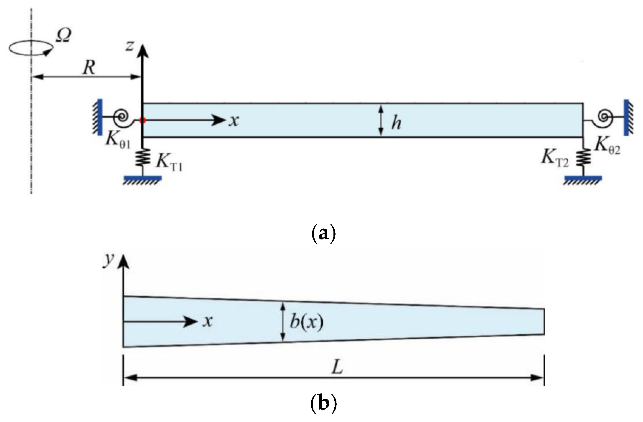
The geometric model of a rotating non-uniform FG-CNTRC beam with boundary relaxation is shown in
Figure 1. The Cartesian coordinate system O-
xyz is introduced, with the origin located at the center of the cross-section at the left end of the beam, and the
x-,
y-, and
z-axes along the directions of length
L, width
b(
x), and thickness
h, respectively. The width
b(
x) varies continuously along the beam length, as shown in
Figure 1b. The beam is mounted on the hub with radius
R, rotating around the
x-y plane at a constant rotating speed
Ω. Due to boundary relaxation, constraints of the supports at both ends of the beam are no longer rigid. The tensile–compressive stiffnesses of the two supports are denoted by
KT1 and
KT2, respectively, while the torsional stiffnesses are denoted by
Kθ1 and
Kθ2, respectively.
2.1. Effective Material Properties of FG-CNTRC Beam
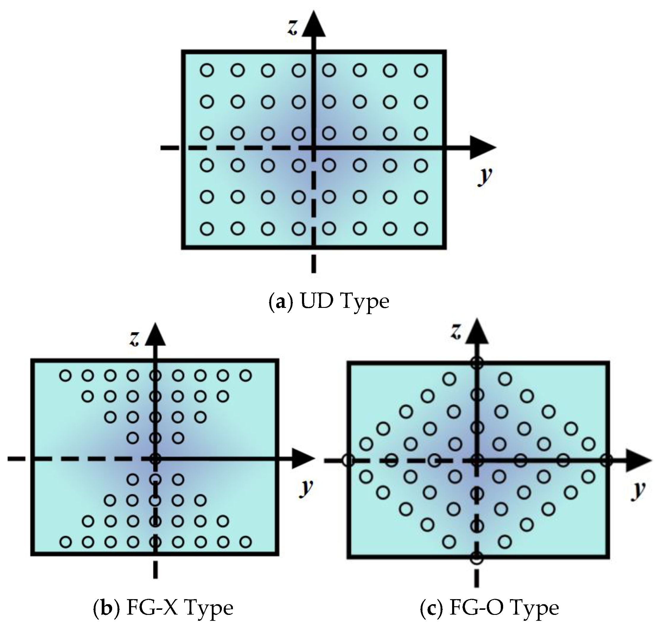
As shown in
Figure 2, there exist three common distribution modes of CNTs across the beam cross-section, including “O” distribution (FG-O), “X” distribution (FG-X), and uniform distribution (UD). All three layouts feature geometric and material symmetry about the beam mid-plane, which constitutes the core symmetry characteristic of the functionally graded structures investigated in this work. Their corresponding CNT volume fractions
Vcn(
z) can be expressed as functions of the thickness coordinate
z [
25,
33]:
where the total volume fraction
of CNTs is a constant independent of the distributions, as follows [
25,
33]:
where
wcn stands for the mass volume fraction of CNTs, and
ρcn and
ρm are the densities of CNTs and matrix.
FG-CNTRC is a novel composite material composed of an isotropic matrix and functionally graded CNTs. The CNTs are continuously distributed along the thickness direction of the beam. According to the modified Mori–Tanaka model and the generalized mixture principle, the effective material properties of FG-CNTRCs can be obtained by introducing the scale effect and efficiency parameters of carbon nanotubes as follows [
25,
33]:
where
and
are the elastic moduli of CNTs, and
denotes the shear modulus of CNTs. Subscripts 11 and 22 represent the directions along and perpendicular to the CNT axis, respectively.
Em and
Gm are the elastic and shear moduli of the matrix material, respectively. Variables
η1,
η2, and
η3 are the efficiency parameters of CNTs determined by molecular dynamics (MD) simulations.
Vm(
z) is the volume fraction of the matrix related to the coordinate
z and satisfies the relation
Vcn (
z) +
Vm (
z) = 1, where
Vcn(
z) is the volume fraction of CNTs.
The effective Poisson’s ratio
ν12(
z) and density
ρ(
z) of FG-CNTRCs can be expressed as:
where
and
νm are the Poisson’s ratios of CNTs and matrix, respectively.
2.2. Governing Equation
Based on the Euler–Bernoulli theory, which is suitable for slender beams with a slenderness ratio of
L/
h ≥ 10, the displacement field at any point on the beam in the Cartesian coordinate system
o-
xyz can be expressed as [
10]:
where
U1 (
x,
z,
t),
U2 (
x,
t), and
U3 (
x,
t) represent the displacement components of an arbitrary point in the
x-,
y-, and
z- axes, respectively.
W(
x, t) is the transverse displacement of the mid-plane, and the prime symbol ( )′ denotes differentiation with respect to
x.
The constitutive relation can be obtained as:
where the expression of strain
εx can be given as follows by introducing the von Kármán nonlinear geometric assumption [
31]:
The potential energy
UP of the dynamic system can be defined as:
where
US represents the strain energy generated by the bending of the beam, and
UR represents the potential energy generated by the boundary relaxation, expressed by:
Combining Equations (5) and (14)–(16), Equation (16) can be rewritten as:
where
Dy and
A11 are the bending stiffness and tensile stiffness of the beam, respectively, expressed by:
The kinetic energy
T generated by the vibration of the system is given as:
where the linear density
m is defined as:
The expression of the centrifugal force
FC generated by rotational motion is calculated as:
Hence, the external work done by the centrifugal force
FC is evaluated as [
7]:
According to Hamilton’s principle:
and substituting Equations (15)–(24) into Equation (25), the vibration equation of a rotating FG-CNTRC beam with constrained imperfections can be obtained as follows:
Meanwhile, the boundary conditions are derived as:
It can be seen from Equation (26) that the axial centrifugal force only exists in the linear part and affects the linear stiffness of the system. Boundary relaxation does not alter the form of the governing equation. The boundary conditions (27)–(30) indicate that the existence of boundary relaxation causes the supports at both ends of the beam to no longer limit the displacement; that is, the beam ends no longer satisfy the displacement boundary conditions. Hence, boundary conditions are required to constrain the beam ends. In this case, the centrifugal force and the variation in the cross-section affect the shear equilibrium condition at the boundary, thus changing the boundary condition of the beam.
Ignoring the nonlinear term in Equation (26), the free vibration equation of a rotating FG-CNTRC beam with boundary relaxation is obtained, which is denoted as:
Considering the variation of the cross-section, the width
b continuously changes in the
x direction as:
where
bL is the width of the cross-section of the left end, and
c is the cross-section gradient coefficient.
Substituting Equation (32) into Equation (26), the governing equation of a rotating non-uniform FG-CNTRC beam is obtained as:
where the bending stiffness
Dy0 and linear density
m0 of the system at the left boundary can be expressed, respectively, as:
Substituting Equation (32) into boundary conditions (27)–(30), it yields
2.3. Dimensionless Procedure
In order to analyze the influence of different parameters, dimensionless parameters are introduced as follows:
Inserting the above dimensionless parameters into the governing equation (33) and the boundary conditions (35)–(38), the dimensionless forms of the governing equation and boundary conditions are obtained as follows:
Dimensionless governing equations:
Dimensionless boundary conditions:
3. Differential Transformation Method (DTM)
The free vibration equation of a rotating FG-CNTRC beam with variable cross-section is obtained as follows:
The analytical solution of the ordinary differential Equation (45) with variable coefficients cannot be obtained directly. Some commonly used methods for solving differential equations in boundary value problems, such as the Galerkin method, the assumed mode method, and the Ritz method, are more suitable for solving problems under classical boundary conditions. In the present model, the centrifugal force induced by rotation, boundary relaxation, and cross-sectional gradient are coupled at the boundary, making the boundary conditions highly complicated. These methods mentioned above are not good at dealing with complex boundary problems. Some numerical methods, such as the differential quadrature method (DQM), can deal with complex boundary conditions but can only obtain numerical solutions. Therefore, the differential transformation method (DTM) is introduced in this section to obtain its solution. The differential transformation method is based on the Taylor series expansion and approximates the solution in polynomial form. Compared with other methods, DTM has a simple implementation and high accuracy and is effective for solving differential equations with variable coefficients and complex boundary conditions [
8,
32].
In this subsection, the partial differential Equation (45) with variable coefficients is transformed into an ordinary differential equation by the method of separation of variables. Based on the assumption of simple harmonic vibration, the displacement form of the beam is written as follows:
where i is the imaginary unit and
ω is the natural frequency.
Substituting Equation (46) into Equation (45), it yields:
In Equations (46) and (47), the displacement function
w (
ξ) is expanded by the Taylor series at
ξ = 0 as follows:
Substituting Equation (48) into Equation (47) and equating like powers of ε, the following equations are obtained:
According to Equations (49)–(52), the relationship between the undetermined coefficients
pj can be obtained, which can be expressed in matrix form as follows:
where
P = {
p0,
p1,
p2, …,
pj + 4}
T. T he coefficient matrices
K and
M are given in
Appendix A. So far, Equation (53) yields infinite solutions, as there are four more unknowns than equations. Meanwhile, there are four boundary conditions left. Next, relying on the boundary conditions, Equation (53) can be solved.
Substituting Equation (48) to discretize Equations (41)–(44), it yields:
The expression (54)–(57) in matrix form is written as:
where the coefficient matrix
KB is given in
Appendix A.
Combining Equation (53) and Equation (58), the following homogeneous linear equations can be constructed:
The natural frequency of the system can be solved when the determinant of the coefficient matrix in Equation (59) is equal to zero.
4. Results and Discussion
In this section, the effects of several parameters, including CNT distribution pattern, CNT volume fraction, rotational speed, hub radius, and boundary relaxation, on the natural frequencies of the beam are investigated through numerical simulations. The geometric parameters of the beam model are presented in
Table 1. In this research, Poly (methyl methacrylate) (PMMA) acts as the matrix material, and single-walled carbon nanotubes (SWCNTs) act as the reinforcement. Material parameters are set as:
Em = 2.5 GPa,
vm = 0.3,
ρm = 1190 kg/m
3,
= 5.6466 TPa,
= 7.08 TPa,
= 1.9455 TPa,
ρcn = 1190 kg/m
3,
vcn = 0.3. The CNT efficiency parameters with different volume fractions are displayed in
Table 2.
Unless otherwise stated, dimensionless parameters are taken in the following parameter analysis:
,
r = 0.2,
c = 0.5,
ηT1 = 107,
ηT2 = 0,
ηθ1 = 107,
ηθ2 = 0. For the convenience of discussion, the tensile relaxation coefficient
RT and torsional relaxation coefficient
Rθ of the support are introduced as:
When RT = Rθ = 0, it means that the constraint effect is the strongest, and the support is not relaxed. The larger RT and Rθ are, the weaker the constraint effect and the greater the degree of relaxation is.
4.1. Validation
In order to ensure the accuracy and efficiency of results obtained by DTM, the truncation order
j of the Taylor series should be selected appropriately.
Table 3 lists the convergence of the first three natural frequencies of the beam with increasing different truncation order
j. It can be seen that, as
j increases, the variation in results gradually decreases, indicating that the results obtained by DTM have converged when
j = 35. To ensure accuracy while improving efficiency, the numerical results in the following parametric analysis subsections are obtained by adopting
j = 40.
To further validate the accuracy of the present DTM formulation, a comparative study with the finite element method (FEM) is carried out. In the modeling process, 20-node layered SOLID186 elements are adopted in ANSYS 2022 R2 software. The comparison results are presented in
Table 3, where the relative error
. It is shown that the difference between the FEM values and the DTM results is very slight, and all relative errors are controlled within 0.53%, which validates the accuracy and reliability of the present semi-analytical solution.
Then, the semi-analytical DTM solution derived in this work is cross-verified against the results reported by Chen and Du [
34]. For the case without cross-sectional variation (
c = 0), the first three natural frequencies under
r = 0, 1, 2, 3 and various rotational speeds
are listed in
Table 4. It can be seen that the agreement between the present method and the previous literature is reasonable, with a maximum relative deviation of only 0.094% under all conditions. When
r = 0, the frequencies of all orders obtained by the two methods are identical. As the rotating speed increases, the centrifugal tension effect is intensified, and the frequency discrepancies corresponding to different hub radiuses increase gradually. Higher-order modes present slightly larger errors than the first-order mode due to their more intricate mode shapes, yet all deviations remain negligible. Combined with the FEM verification results in
Table 3, the accuracy of the present results is convincing.
4.2. Parameter Analysis
This subsection discusses the effect of material properties, rotating speed, hub radius, cross-section gradient, and boundary relaxation on the natural frequency ω of the rotating beam.
4.2.1. Influence of Material Properties
Table 5 illustrates the effect of CNT distribution patterns and total CNT volume fraction on the first three natural frequencies of the rotating non-uniform FG-CNTRC beam. The present predictions clearly reveal that the first three natural frequencies increase significantly as the CNT volume fraction
increases. The reason for this phenomenon is that the addition of CNTs enhances the effective elastic modulus of the composite material and reduces the density, thereby increasing the natural frequencies. The stiffening effect of CNTs is related to their volume fraction, and it is most significant when a small amount of CNTs is added.
At
= 0, the beam is purely composed of a polymer matrix, so identical frequency values are observed for FG-O, UD, and FG-X distributions. For any given volume fraction, the FG-X configuration produces the highest natural frequencies, followed by UD, while FG-O yields the lowest values. This phenomenon arises because more CNTs are distributed near the top and bottom surfaces, far from the neutral axis under the FG-X pattern, which significantly improves the bending stiffness of the beam. In addition, the gap of natural frequencies among three distribution modes becomes wider as
grows, indicating that the arrangement of CNTs exerts a more prominent stiffening effect with higher CNT content. Quantitatively, when the CNT volume fraction of FG-X increases from 0.12 to 0.17 (a 41.7% rise in CNT content), the natural frequency grows by 21.2%. When
further increases from 0.17 to 0.28 (a 64.7% content increment), the frequency only rises by 20.4%. This comparison confirms that the enhancement efficiency of structural stiffness gradually weakens with the continuous addition of CNTs. Therefore, the more CNTs are distributed at the ends of the cross-section, the greater the stiffness of the system. The comparative data in
Table 5 quantitatively demonstrate that both the content and through-thickness distribution of CNTs are critical design parameters to adjust the dynamic stiffness and natural vibration characteristics of FG-CNTRC rotating beams.
4.2.2. Influence of Rotating Motion
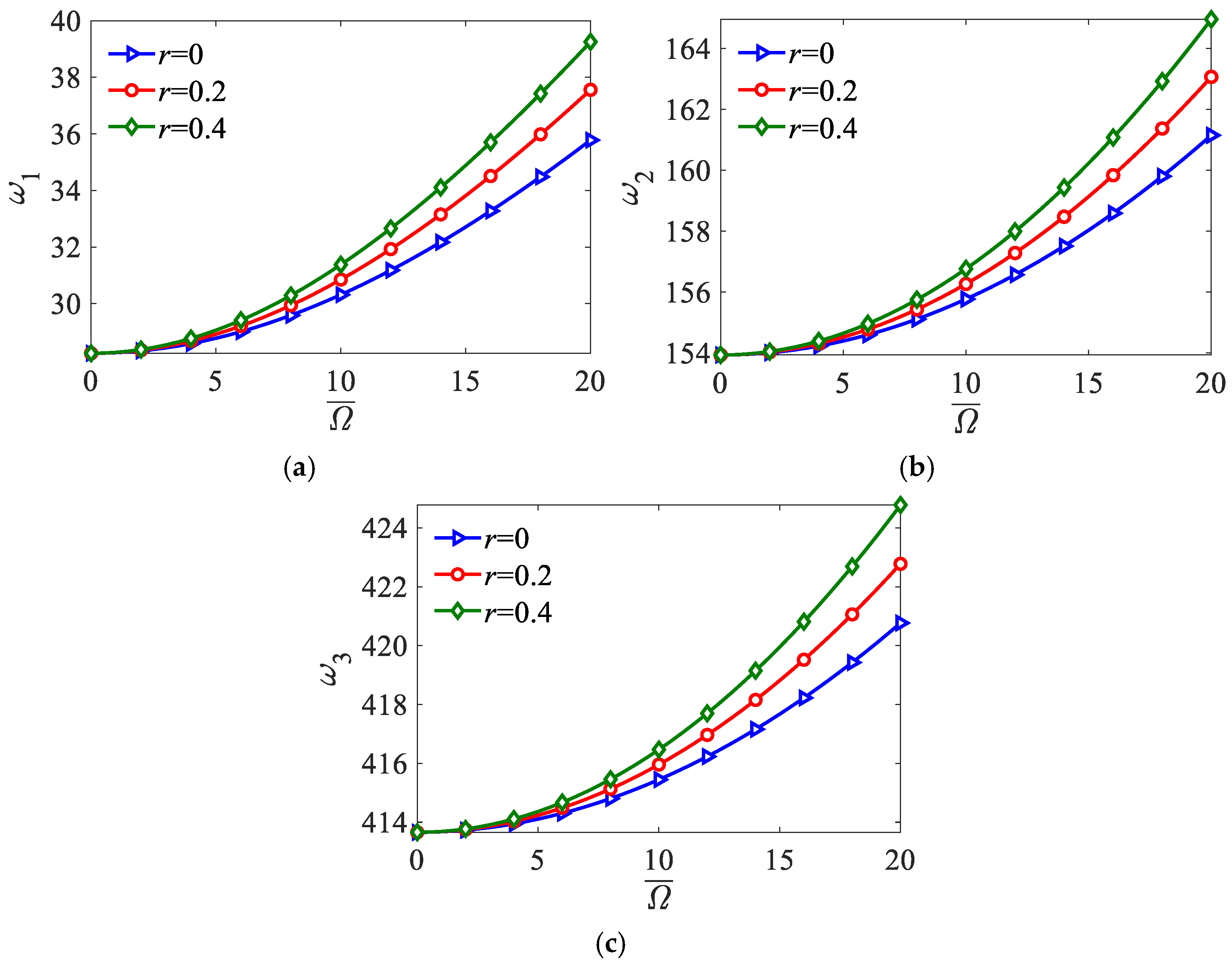
Figure 3 reveals the variation of the first three natural frequencies of the non-uniform FG-CNTRC beam with the rotating speed
and hub radius
r. The centrifugal force generated by rotating motion enhances the structural stiffness. Therefore, as the rotating speed
and hub radius
r increase, the centrifugal force increases, causing the first three natural frequencies to rise. According to Equation (23), the centrifugal force
FC is directly proportional to
. Consequently, as the value of
increases, the rate of increase in centrifugal force
FC accelerates, leading to a more pronounced trend in the increase in the system’s natural frequencies. Meanwhile, the effect of the hub radius
r on the natural frequency depends on
; when the structure does not rotate (
), no centrifugal force is generated, and the hub radius
r will not affect the natural frequencies. Therefore, at the origin point of
Figure 3, different values of the hub radius
r correspond to the same natural frequencies. As the rotating speed increases, the influence of hub radius
r on the centrifugal force
FC and the natural frequencies increases.
Additionally, when comparing the three modes, higher-order modes show more obvious frequency differences across hub radius r than the fundamental mode. High-order bending modes feature more complicated curvature distributions along the beam length, making them more sensitive to the axial tensile load introduced by rotation and hub offset. Even so, the monotonic growth trend of frequency with and r remains consistent for the first, second, and third orders. From an engineering perspective, both increasing rotational speed and enlarging the hub mounting radius serve as effective ways to raise natural frequencies and avoid low-frequency resonance. Nevertheless, hub radius adjustment only works for high-speed rotors; it barely changes dynamic performance under low-speed operation.
4.2.3. Influence of Cross-Section Gradient
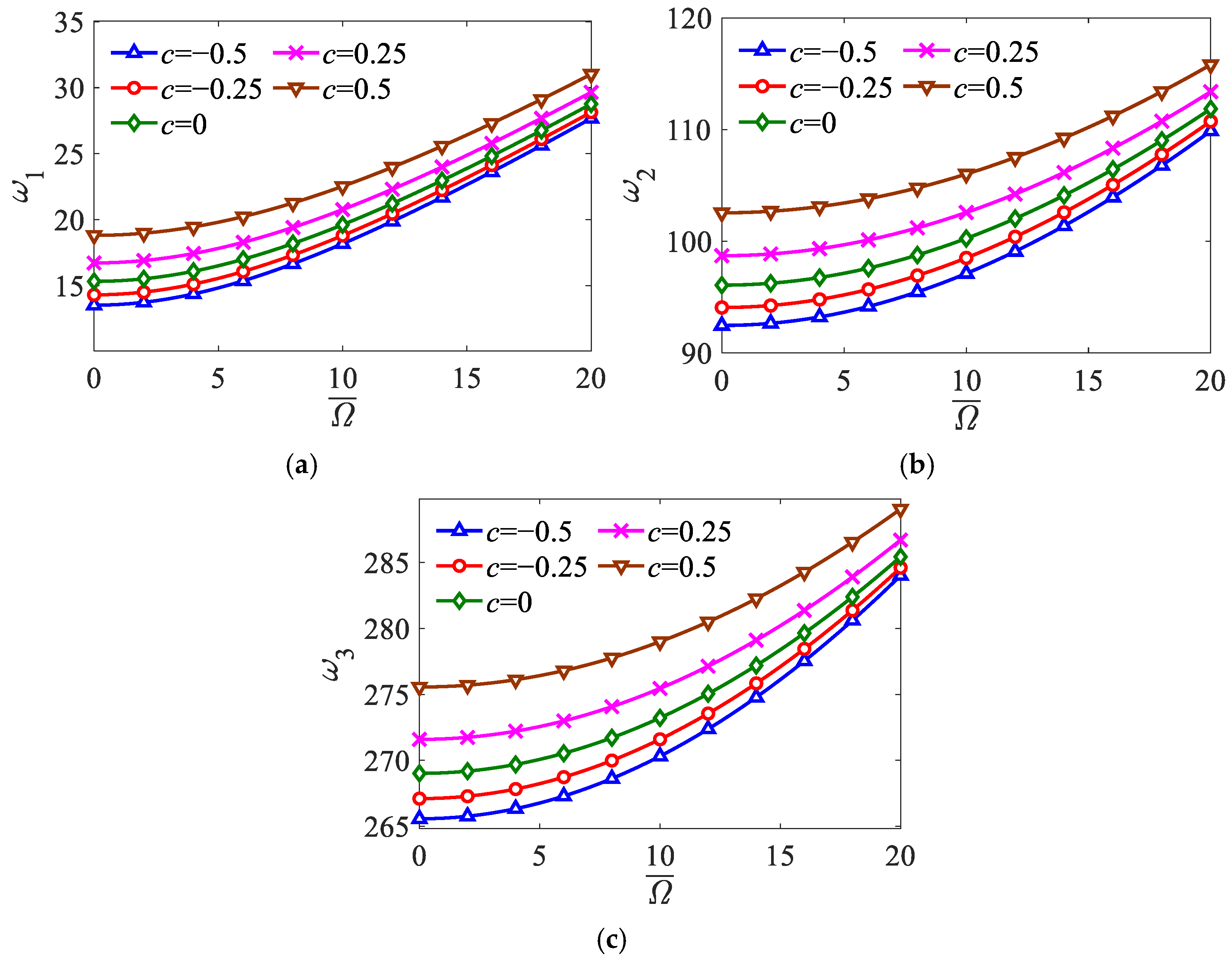
Figure 4 shows the influence of the cross-section gradient coefficient
c on the first three natural frequencies of the rotating non-uniform FG-CNTRC beam. When
c > 0, the cross-section of the beam at the free end is smaller than that at the restrained end. When
c < 0, the cross-section of the beam at the free end is larger than that at the restrained end. As the cross-section gradient coefficient
c increases, the cross-section at the free end of the beam decreases, leading to a reduction in its bending stiffness. Simultaneously, the mass of the beam also decreases. The decrease in bending stiffness will cause the natural frequencies to decrease, while the decrease of mass will increase the natural frequencies. However, the effect of mass reduction outweighs that of bending stiffness reduction. Therefore, with the cross-section gradient coefficient
c increasing, the natural frequencies increase; that is, the reduction in the cross-section at the free end will produce a stiffening effect on the structure. Moreover, the rotating speed
also changes the extent to which the cross-section gradient coefficient c affects the natural frequencies. When
, the effect of
c is most significant. With the increase in rotating speed, the centrifugal stiffening effect becomes more and more pronounced. In contrast, the stiffening effect resulting from the reduction in the cross-section is weakened, and the increasing trend of the natural frequencies slows down.
For all the first, second, and third modes, the monotonic increasing trend of frequency versus c holds unchanged. Higher-order modes exhibit larger overall frequency variations when adjusting the taper coefficient, since high-order bending deformations rely more heavily on the cross-sectional geometric properties along the beam span.
4.2.4. Influence of Boundary Relaxation
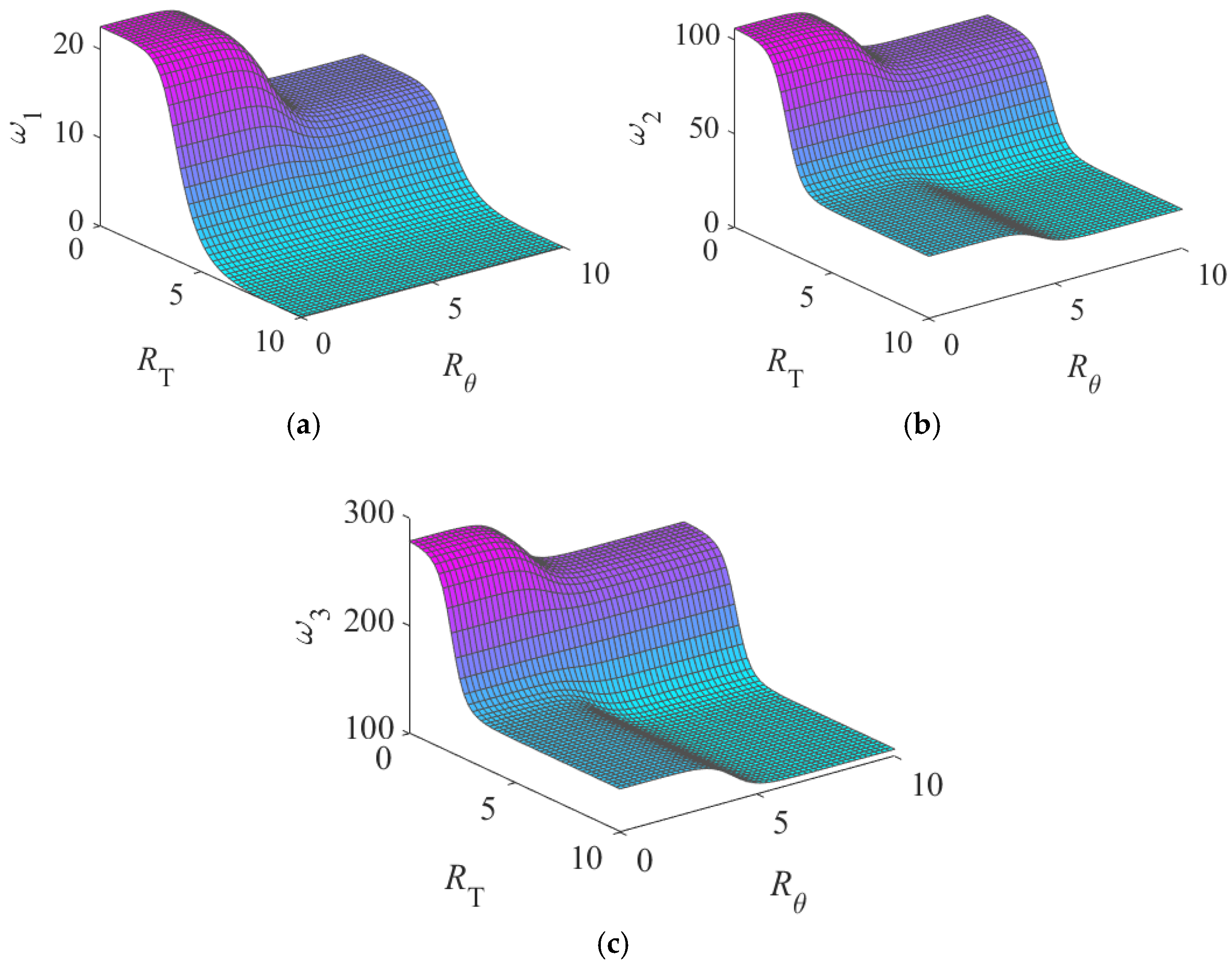
Figure 5 illustrates the variation of the first three natural frequencies of the rotating non-uniform FG-CNTRC beam as the support relaxation coefficients
RT and
Rθ vary. Overall, the trends of the first three natural frequencies are generally similar when
RT and
Rθ change. As
RT and
Rθ increase, indicating a greater degree of support relaxation, the natural frequencies decrease because the stiffness of the system decreases. At the same time, the rate of decrease in natural frequency is also related to the support relaxation coefficients
RT and
Rθ. With the increase in
RT and
Rθ, the rate of decrease in natural frequency first increases and then decreases. When
RT and
Rθ are relatively large or small, the trend of the natural frequency change is not significant.
Nevertheless,
RT and
Rθ have different degrees of influence on the natural frequency. Compared with the torsional stiffness of the support, the tensile stiffness of the support has a greater impact on the natural frequency. Additionally, the influence of support torsional stiffness on the natural frequency depends on the tensile stiffness. When the tensile stiffness of the support is larger, the influence of the torsional stiffness on the natural frequency is greater. Otherwise, it is smaller. For instance, in
Figure 5a, when
RT is equal to 10 and
Rθ increases, the first order natural frequency of the rotating FG-CNTRC beam remains almost unchanged. However, when
RT is equal to 0, a significant decreasing trend in the natural frequency is observed with the increase in
Rθ. This indicates that the tensile stiffness of supports is the dominant factor governing dynamic performance, while torsional relaxation only plays a secondary modifying role.