Article

Simulation-Based Parameter Analysis and Experimental Validation of a Permanent Magnet Eddy Current Damper

1
School of Mechanical and Automotive Engineering, Anhui Polytechnic University, Wuhu 241000, China
2
Wuhu Magnetic Wheel Transmission Technology Co., Ltd., Wuhu 241000, China
*
Authors to whom correspondence should be addressed.
Symmetry 2026, 18(7), 1159; https://doi.org/10.3390/sym18071159
Submission received: 6 May 2026 / Revised: 6 June 2026 / Accepted: 23 June 2026 / Published: 8 July 2026
(This article belongs to the Special Issue Meta-Heuristics for Manufacturing Systems Optimization, 3rd Edition)

Abstract

To address the issue of fatigue failure in conventional coil springs applied in automotive suspensions, a design method for a permanent magnet eddy current damper (PMECD) is proposed. Firstly, the working principle of the proposed method is introduced, and its dynamic model is established to identify the key parameters that affect its primary performance. Subsequently, numerical models for repulsive force and eddy current damping force are established. Simulation results show that the system has the characteristics of axial and radial symmetry, and the magnetic yoke and copper sleeve reduce magnetic leakage, thereby verifying the rationality of the structural design of the proposed method. The thicker the permanent magnet, the greater the magnetic force produced, and there exists a nonlinear relationship between the magnetic force and displacement. In comparison, the magnetic force generated increases with the thickness of the copper sleeve, exhibiting a trend of first increasing and then decreasing. With the increase in the air gap, its impact on the magnetic force presents a variation trend of first decreasing, then increasing, and finally decreasing again. Although the increase in speed leads to little change in the magnetic force, the eddy current damping force gradually increases, which in turn results in an increase in solid losses. Test results show that the differences between theoretical and simulation calculations and experimental results are less than 5%, which verifies the correctness of the method; compared with the eddy current damper without a copper sleeve, the equivalent damping ratio of the eddy current damper with a copper sleeve increases by 103.7%. This study provides a theoretical basis for the future design and optimization of PMECDs.

1. Introduction

Vibration suppression and energy dissipation are critical issues for the safety, durability, and service performance of engineering structures and mechanical equipment under long-term dynamic loads, such as wind-induced vibration, seismic excitation, mechanical vibration, and reciprocating motion. With the advantages of non-contact friction, zero oil leakage, environmental friendliness, and structural symmetry, eddy current dampers (ECDs) have gradually become a preferred choice for vibration control in bridge engineering, high-rise buildings, wind turbines, vehicle systems, and other engineering fields [1,2,3,4,5,6]. Based on the excitation and control principles, eddy current damping technologies can be categorized into passive, semi-active, and active types [7,8].
To improve the vibration reduction performance of ECDs, scholars have carried out extensive innovative research in structural form, working mechanism, and parameter optimization. He et al. [9] proposed a novel spring-type eddy current tuned mass damper (SECTMD) to enhance control performance; the results indicate that the optimal SECTMD enhances the damping ratio by 64% compared with the conventional spring tuned mass damper (STMD). Furthermore, compared with the original structure (OS), the SECTMD reduces the root mean square (RMS) values of displacement and acceleration by 37% and 38%, respectively, under wind load. He et al. [10,11] developed a hybrid excitation eddy current damper that combines an electromagnet and a permanent magnet, revealing the inherent nonlinear characteristics of eddy current damping. Liu et al. [12] developed an eddy current tuned rolling cylinder damper (ECTRCD) to suppress the vibration of large wind turbines; key parameters such as radius ratio, mass ratio, and damping ratio were optimized via simulation methods. Lu et al. [13] proposed an eddy current damper with inserted magnetic iron rods (ECD-MIR) to overcome the limitations of insufficient damping capacity. Song et al. [14] developed a multidimensional eddy current tuned mass damper (MEC-TMD), which effectively suppresses the coupled vibration of eccentric structures by combining non-contact eddy current damping with the tuning characteristics of TMD and adopting a symmetric multi-directional damping design. Umekawa et al. [15] developed a new structure for a multi-degree-of-freedom vortex damper for a liquid hydrogen turbopump to address the vibration problem caused by high-speed rotation of aircraft turbopumps; its damping performance is superior to existing multi-degree-of-freedom eddy current dampers. Wang et al. [16] developed a bi-directional adaptive eddy current pendulum tuned mass damper (AEC-PTMD) with a symmetrical pendulum configuration used for seismic protection of high-rise buildings; the results demonstrate that the system has satisfactory nonlinear seismic protection performance. In order to overcome insufficient multi-band vibration isolation of vehicle seats, an integrated seat damping system with a symmetric magnetic circuit eddy current damper was proposed [17], the vibration suppression characteristics were analyzed through theory and simulation methods, and the results showed that the expected goal could be achieved. The nonlinear damping behavior of traditional ECD is also one of the important factors affecting vibration resistance performance. A velocity-amplified hamburger-shaped eddy current damper (VHECD) was proposed [18], and its dynamic model was established and verified by experimental tests.
Passive ECD has the characteristics of a simple structure, high reliability and no external input energy. Many scholars have also carried out relevant research on the application of passive ECD [19]. Sodano et al. [20] proposed a method of using radial magnetic flux to generate electromagnetic damping force to solve the problem of suppressing lateral vibration. Ebrahimi et al. [21,22] discussed the damping effect of different permanent magnet structures on eddy current passive dampers and then proposed a hybrid electromagnetic shock absorber which integrated active electromagnetic actuation and eddy current passive damping. While maintaining the high-performance damping characteristics of the active suspension, it achieved a failure safety guarantee and reduced energy consumption by more than 70% through about 1570 Ns/m passive damping. Bae et al. [23] studied the eddy current damping characteristics of permanent magnets in conductive tubes through theoretical analysis and experiments, established the theoretical model of eddy current damping, and analyzed and experimentally studied the eddy current damping characteristics. Jimenez et al. [24] analyzed three kinds of structures with an axial distribution and opposite polarity of two-, three- and four-ring permanent magnets and carried out theoretical and experimental analyses. Gori et al. [25] introduced the design and optimization technology for a magnetic spring. The algorithm can optimize the geometry of the permanent magnet spring from the required force–displacement characteristics, so that it has the required curve. Aiming at the weak damping characteristics of a permanent magnet electric suspension system, Fu et al. [26] proposed an optimization index based on the suspension damping ratio to realize the collaborative optimization of magnet and conductive plate parameters. Yang et al. [27] developed a rotary adjustable permanent magnetorheological damper. The damper uses magnetorheological fluid as the working medium and a permanent magnet as the magnetic field source, without an external excitation coil or power supply, and relies on the mechanical rotation mechanism to change the relative position of the permanent magnet and magnetorheological working chamber so as to continuously control the magnetic induction intensity in the working area. Furthermore, the shear yield strength of the magnetorheological fluid is changed to realize stepless adjustment of damping force.
This paper proposes a design method based on permanent magnet eddy current damping (PMECD) to address issues such as the lifespan and susceptibility to damage of existing vehicle suspension damping systems. A dynamic model was established to analyze its mechanical properties under different parameter combinations. Finally, through analysis and comparison of simulation and experimental results, the design principles and performance rules of PMECD were summarized, providing a theoretical basis and technical reference for the engineering application of high-performance and high-durability PMECD.

2. System Composition and Principles

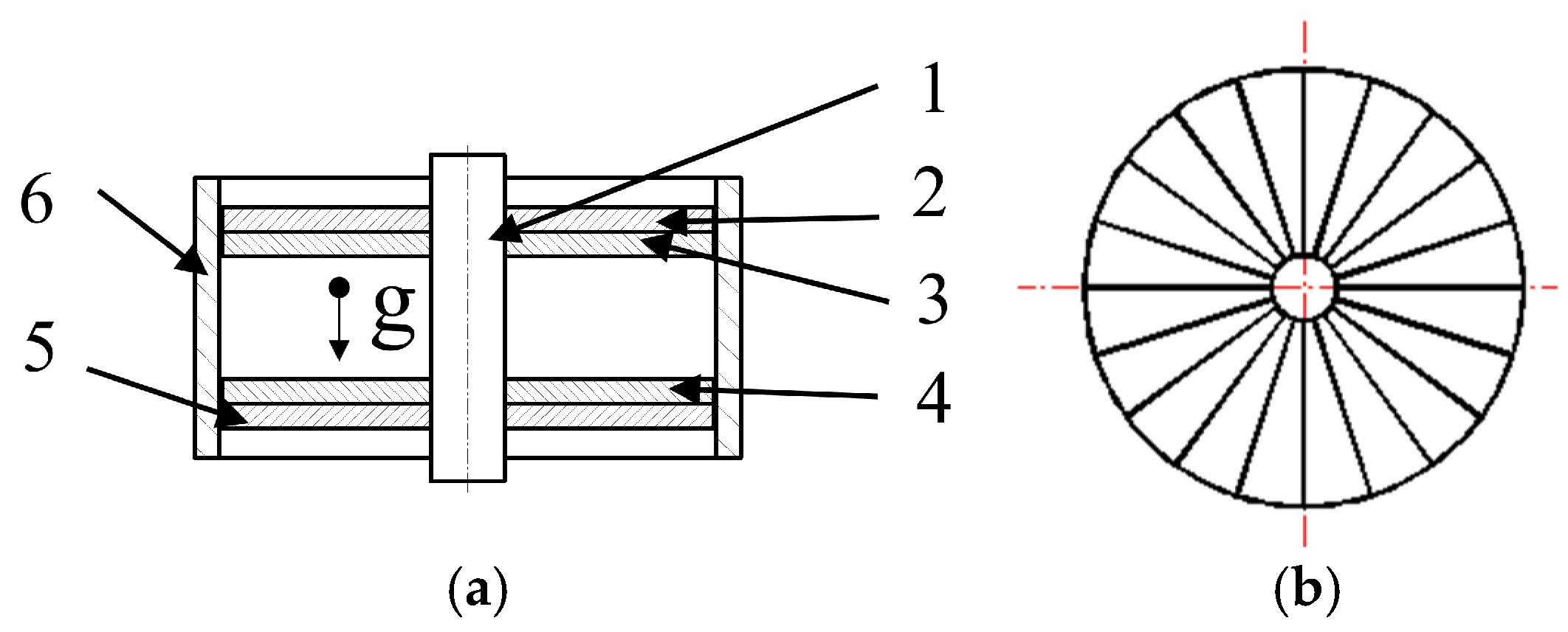
As illustrated in Figure 1a, the PMECD is composed of a central axis, an upper permanent magnet, an upper magnetic yoke, a lower permanent magnet, a lower magnetic yoke, and a copper sleeve. A key structural feature of the damper lies in its axisymmetric design: the upper and lower permanent magnets are each composed of 20 fan-shaped magnet segments, which are symmetrically arranged along the central axis to form a complete axisymmetric structure, with the magnetization direction along the axial direction, as shown in Figure 1b. The upper and lower magnetic yokes are designed to reduce magnetic field leakage. The working principle of the damper is elaborated as follows: the magnetization direction of the upper permanent magnet is opposite to that of the lower permanent magnet. The lower permanent magnet and the lower magnetic yoke are rigidly fixed to the central axis, while the upper permanent magnet and the upper magnetic yoke are integrated into a single component that can move freely along the axial direction of the central axis. When the upper permanent magnet moves downward, eddy currents are induced in the copper sleeve in accordance with Lenz’s law; these eddy currents generate an opposing magnetic field to resist the movement of the upper permanent magnet, thereby producing an eddy current damping force, F e d . Meanwhile, due to the axisymmetric arrangement of the upper and lower permanent magnets, the like magnetic poles of the two permanent magnets are symmetrically aligned, resulting in a repulsive force, F r e , of the same name on the magnets, called the spring force of the permanent magnet. This integrated structure based on the spring force, F r e (N), of the permanent magnet, which bears vertical loads, and the eddy current damping force, F e d (N), forms a stable mass spring damping system. Therefore, the dynamic equation of the PMECD is shown in Equation (1).
F re + sign ( v ) F ed = m t ( g ± v ˙ )
where m t (kg) is the equivalent mass loaded on the upper permanent magnet, v (m/s) is the relative moving speed of the permanent magnet, sign ( v ) > 0 when the upper permanent magnet approaches the lower permanent magnet, sign ( v ) < 0 when it recedes, and sign ( v ) = 0 for v = 0 , g (m/s2) denotes gravitational acceleration. The plus/minus sign on the right side of the equal sign, when the acceleration v ˙ is in the same direction as g, it is plus, and when it is in the opposite direction, it is minus.
Therefore, for the PMECD, the eddy current damping force, F ed , and the repulsive force, F r e , between permanent magnets serve as critical performance indicators in the design of permanent magnet damping springs, and it is imperative to systematically analyze the parameters that influence these performance indicators. To accurately characterize the relationship between design parameters and damping performance, a mathematical model integrating symmetry-related factors will first be established. Subsequently, the validity and accuracy of this mathematical model will be verified through combined simulation and experimental tests, ensuring that the model can reliably reflect the effect of the key parameters on the overall performance of the permanent magnet damping spring.

3. Mathematical Models

3.1. Mathematical Model of Eddy Current Damping Force F e d

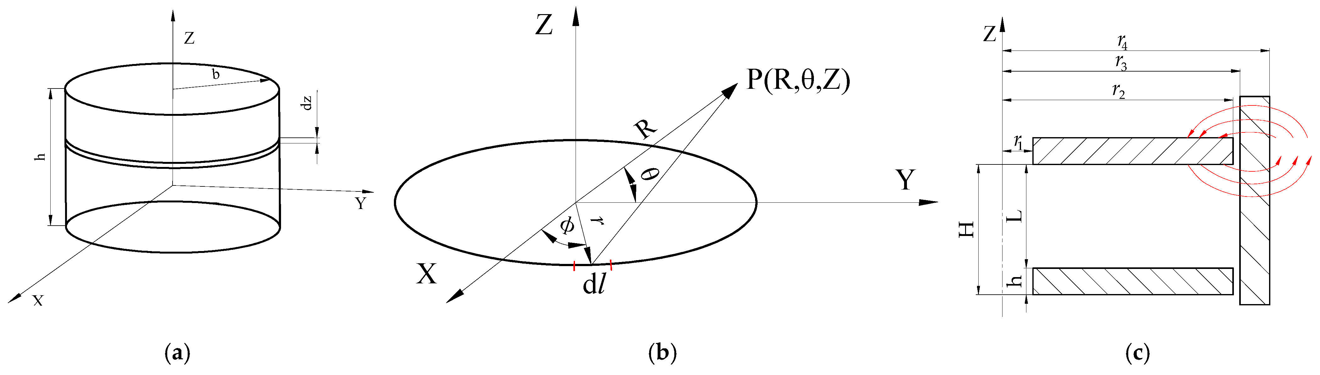
The cylindrical permanent magnet, shown in Figure 2a, is uniformly magnetized along the positive Z-axis by default, and a coordinate system is established at half of its height. According to the principle of differentiation, take an infinitesimally small cylinder with a thickness of d z and take its minimum arc length as d l , as shown in Figure 2b. Since the magnetic field is axisymmetric, a cylindrical coordinate system is used for calculation [28,29]. Taking a point P in the YOZ plane, the distance from the differential element to the P point can be defined as
R 1 = R r
d l = b sin ϕ d ϕ a x + b cos ϕ d ϕ a y
where R = y a y + z a z , r = b cos ϕ a x + b sin ϕ a y , and b (mm) is the radius of the cylindrical permanent magnet.
By applying the Biot–Savard law, the magnetic flux density of the ring loop illustrated in Figure 2b can be derived and expressed as follows [30]:
d B = μ 0 M 0 4 π d l × R ^ 1 R 1 2
where μ 0 (H/m), M 0   ( A / m ) , d l , and R ^ 1 are the permeability and the magnetization per unit length; the vector of the infinitesimal strip; and the unit vector from the source point to the field point, P, respectively.
In the cylindrical coordinate system r , θ , z , the circumferential component B θ   =   0 , so the magnetic flux density at any point can be written as
B = B r r + B z z
where B r and B z   ( t e s l a ) are the magnetic flux density in the directions of r and z, respectively.
According to Equations (2)–(5), the radial magnetic density and axial magnetic density are respectively:
B r ( r , z , z 1 ) = μ 0 M 0 b 4 π h 2 h 2 ( z z 1 ) I 1 ( b , r , z z 1 ) d z 1
B z ( r , z , z 1 ) = μ 0 M 0 b 4 π h 2 h 2 I 2 ( b , r , z z 1 ) d z 1
I 1 ( b , r , z z 1 ) = 0 2 π sin ϕ [ b 2 + r 2 + ( z z 1 ) 2 2 b r sin ϕ ] 3 2 d ϕ
I 2 ( b , r , z z 1 ) = 0 2 π b r sin ϕ [ b 2 + r 2 + ( z z 1 ) 2 2 b r sin ϕ ] 3 2 d ϕ
where z 1 is the distance in the Z direction from the center of the magnetized infinitesimal strip and I 1 ( b , r , z z 1 ) and I 2 ( b , r , z z 1 ) are intermediate variables.
As shown in Figure 2c, the PMECD model has been simplified, mainly including the upper permanent magnet, lower permanent magnet and copper sleeve. The permanent magnet is magnetized axially. According to the distribution of magnetic induction lines, the magnetic induction density in the XY plane at any height, Z, can be regarded as the magnetic induction density generated by the difference between the solid cylindrical permanent magnet with radius r 2   ( m m ) and radius r 1   ( m m ) . Therefore, the magnetic induction intensity, B r ( r , z ) , can be expressed as:
B r ( r , z ) = 2 [ B r 2 ( r , z ) B r 1 ( r , z ) ]
where B r ( r , z ) is the total radial magnetic density of the ring magnet at radius r on the XY plane at height z , B r 2 ( r , z ) is the radial magnetic density of the solid permanent magnet with radius r 2 on the XY plane of height z , B r 1 ( r , z ) is the radial magnetic density of the solid permanent magnet with radius r 1 on the XY plane of height z , and r 1 ( m m ) and r 2 ( m m ) are the inner radius and the outer radius of the permanent magnet. Within the narrow, active interaction zone between the magnet and the copper sleeve, the axial variation of B r ( r , z ) is negligible compared to its radial variation. For the purpose of approximate analytical evaluation of the Lorentz force, the radial magnetic flux density, B r ( r , z ) , is treated as constant over the effective interaction region of the copper sleeve. This engineering approximation simplifies the integral while maintaining sufficient accuracy for the system-level performance analysis, and its validity is confirmed by both numerical simulation and experimental validation.
The PMECD is externally shrouded in the copper sleeve, and when the air gap distance between the permanent magnet and the copper sleeve is very small, the magnetic leakage is almost zero. When the relative motion speed of the permanent magnet and the conductor is v   ( m / s ) , the current density, J ( A / m 2 ), on the conductor due to eddy currents can be expressed as
J = σ ( v × B )
where σ ( S / m ) is the conductivity of the copper sleeve.
The magnetization direction of the permanent magnet is parallel to the direction of motion, and according to the definition of the Lorentz force, the damping force in the Z direction can be obtained as F e d ( N ) :
F ed = V J × B d V
where d V = r d r d θ d z in the cylindrical coordinate system, representing the microvolume unit of the copper sleeve.
Since B r ( r , z ) has nothing to do with the Z coordinate or with the copper sleeve area, 0 2 π d θ = 2 π , and the integration of the Z-axis is simplified to multiply by ( H h ) , where h and H (mm) are the thickness of the permanent magnet and the polar distance between the upper and lower permanent magnets, respectively.
Thus, Equation (12) can be simplified as follows:
F e d = 2 π σ v ( H h ) r 3 r 4 r B r 2 ( r , z , z 1 ) d r
where r 3 and r 4 (mm) are the inner radius and the outer radius of the copper sleeve and the negative sign indicates that the direction of the damping force is opposite to the direction of the velocity.
Then, the damping coefficient, c , can be expressed as
c = 2 π σ v ( H h ) r 3 r 4 r B r 2 ( r , z ) d r
The copper sleeve generates eddy currents, which are affected by the skin effect, causing the current density inside the conductor to decrease exponentially with the depth d s from the surface of the conductor [31]. The skin effect can be expressed as
J = J s e d s Δ p
where J s ( A / m 2 ) and p (mm) are the surface current density and penetration depth, respectively.
The penetration depth is the depth at which the current density decreases to 1 e of the surface current from the conductor surface inward. p can be expressed as
Δ p = 1 π σ μ a f
where f (Hz) is the eddy current frequency and μ a (H/m) is the absolute magnetic permeability of the conductor. By correcting Equations (13) and (14), we can obtain
F e d = 2 π σ v ( H h ) r 3 r 4 r B r 2 ( r , z , z 1 ) e r r 3 Δ p d r
c = 2 π σ v ( H h ) r 3 r 4 r B r 2 ( r , z ) e r r 3 Δ p d r

3.2. Mathematical Model of Magnetic Repulsion F r e

For the permanent magnet model shown in Figure 2c, the spatial magnetic flux density, B g ( Gs ) , can be derived and expressed as follows [32]:
B g = 0.96 B r × [ L r 1 2 + L 2 L r 2 2 + L 2 ]
where L (mm) is the distance between two permanent magnets.
Therefore, the repulsion force, F r e , between permanent magnets can be expressed as follows [33,34]:
F re = 1.5 1 + α L ( B g 4965 ) 2 A
where A ( mm 2 ) is the relative working area between the upper permanent magnet and the lower permanent magnet; α is the correction factor, usually taken as 3–5 (when the clearance is large, take the large value, and when the clearance is small, take the small value); and 1.5 is a pure empirical coefficient for compensating for the edge effect of the magnet and the shape of the magnet. The average magnetic induction intensity B g at the working point of neodymium iron boron materials under different grades is approximately 4965 Gs.
Based on the above analysis, it can be concluded that the primary factors influencing the eddy current damping force and repulsion force include the thickness of the magnet, the thickness of the copper sleeve, the air gap size, and the relative motion speed of the two magnets inside the sleeve. Therefore, a targeted analysis of these parameters is necessary.

4. Simulation Results and Discussion

To analyze the influences of magnet thickness, copper sleeve thickness, air gap size, and relative motion speed of two permanent magnets inside the sleeve on magnetic force, a simulation model of the PMECD was established using Ansys Electronics 2024 R2. The boundary conditions were set as follows: Integrated Zero Tangential H Field, grid convergence: length-based refinement, the number of grids is 56,572, solver type: transient, the nonlinear residual of the solver is 0.001, a total time of 15 s, and a step size of 1 s. The material and dimensional parameters are presented in Table 1 and Table 2, respectively. All materials and components are provided by Wuhu Magnetic Wheel Transmission Technology Co., Ltd., Wuhu City, China.
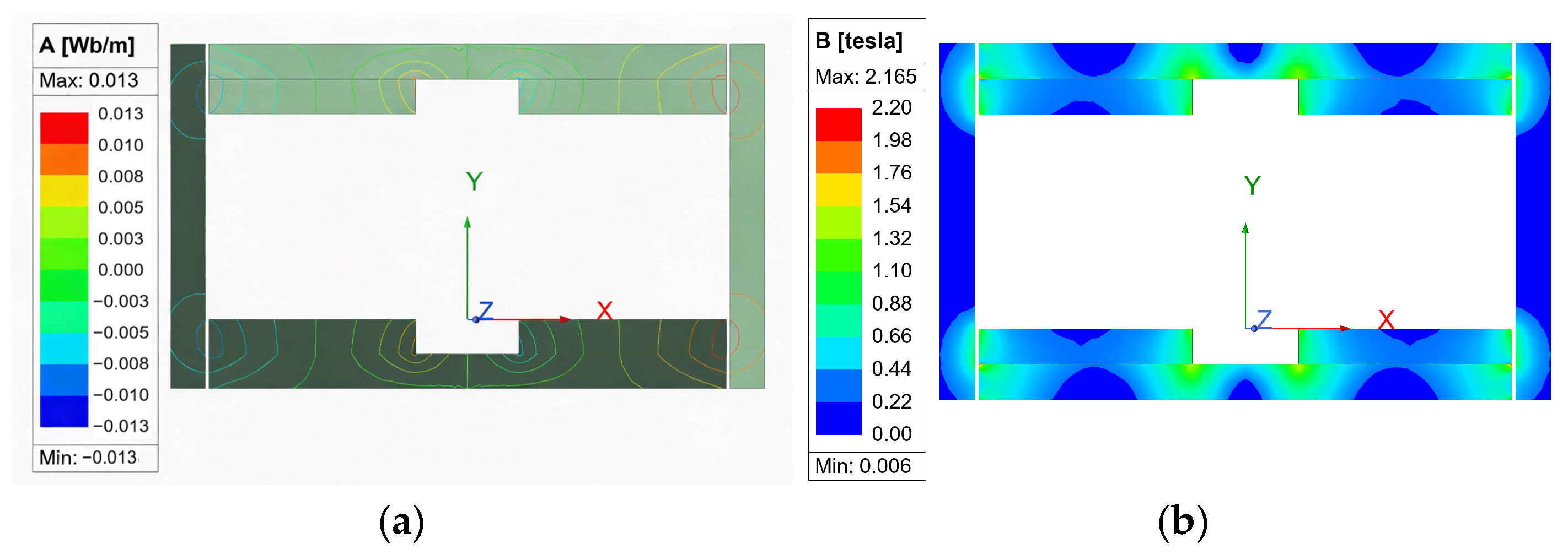
To investigate the magnetic field distribution of the PMECD, a two-dimensional mathematical model was established in Maxwell for simulation. The magnetic field distribution contour plot and flux lines plot are shown in Figure 3. The results reveal that the magnetic field of the PMECD exhibits axial spatial symmetry. Additionally, the magnetic field is confined by the iron yoke and copper sleeve, which effectively restrains magnetic field penetration through the yoke and reduces magnetic leakage to the external environment. This further verifies the rationality of the magnetic field configuration adopted in this study.
To ensure the uniformity of the repulsive force between the two permanent magnets, based on the symmetry of the PMECD structure, the initial simulation parameters were set as follows: the thickness of the permanent magnet, the thickness of the copper sleeve, the air gap size, and the relative movement speed of the two permanent magnets inside the sleeve were set to 10 mm, 10 mm, 1 mm, and 5 mm/s, respectively. Additionally, the distance, L, between the upper and lower permanent magnets was set to 60 mm.
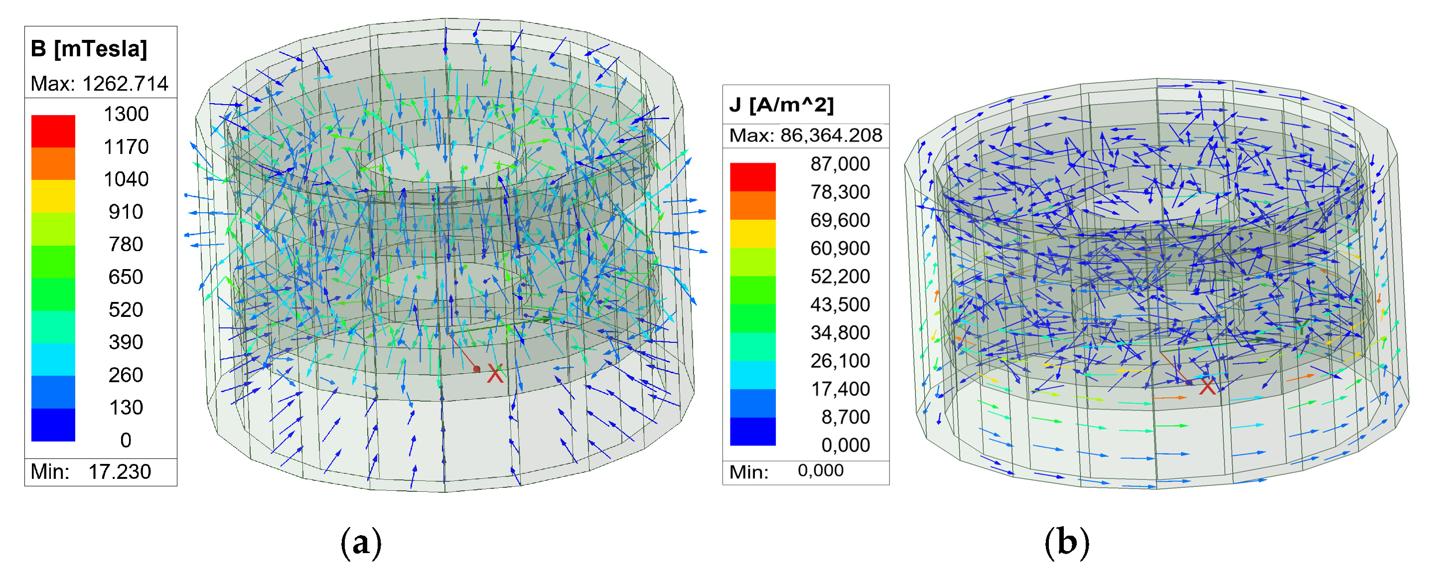
Transient simulations were performed using a 3D simulation model, and the results at 3 s are shown in Figure 4. The results demonstrate that the maximum magnetic flux density is 1262.714 mTesla , and the magnetic field lines are mainly distributed on the upper magnet, lower magnet, and copper ring. Eddy currents are induced on the copper sleeve, and the maximum current density formed near the moving magnet is 86,364.208 A / m 2 , which further verifies the rationality of the designed structure.

4.1. Influence of Permanent Magnet Thickness

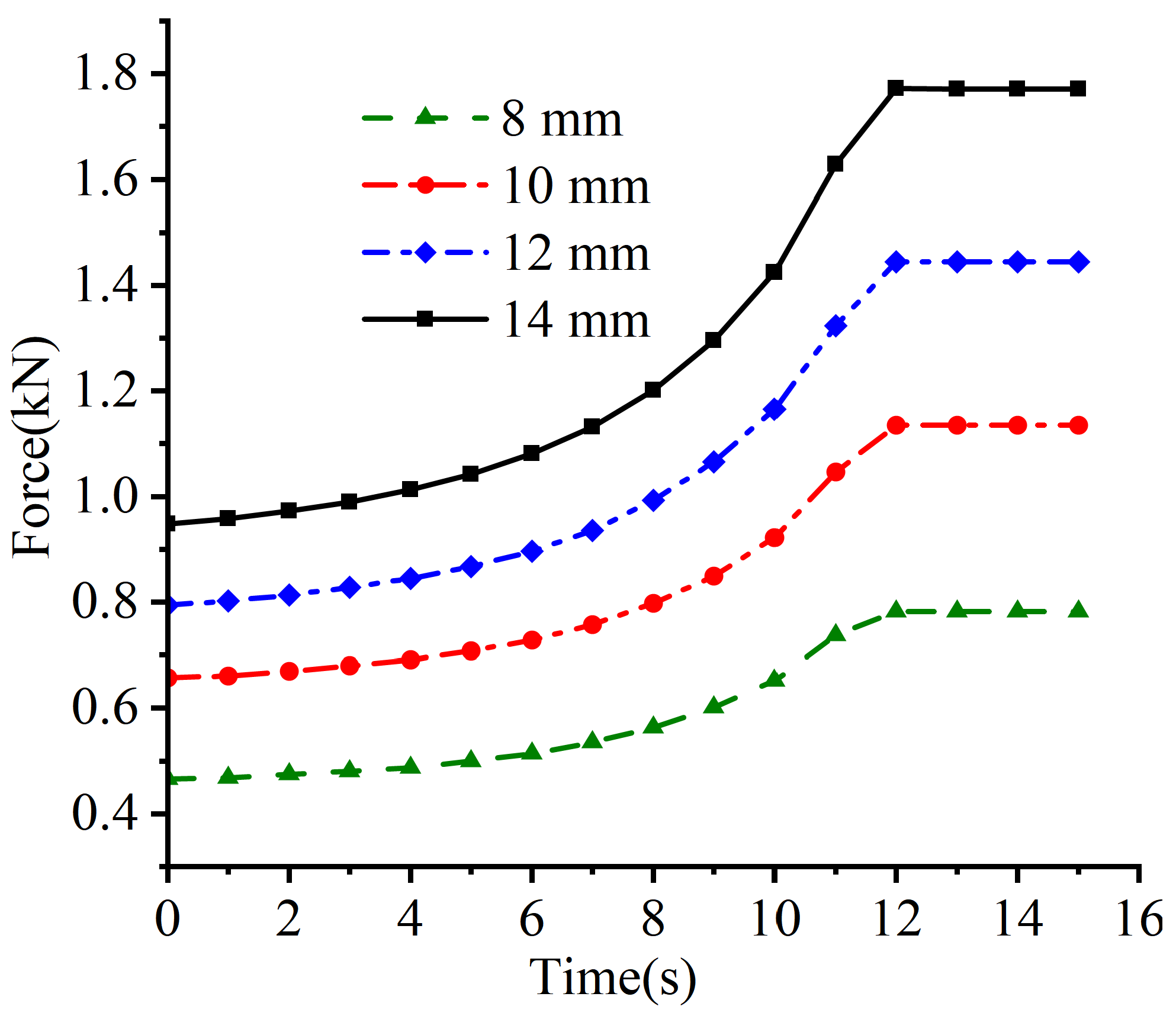
Simulation tests were conducted with the permanent magnet thickness set to 8 mm, 10 mm, 12 mm, and 14 mm, while the other key parameters remained unchanged from the initial simulation settings.
As shown in Figure 5, the results demonstrate that force and displacement exhibit nonlinear characteristics. At the initial displacement stage, the force grows relatively slowly, whereas it increases rapidly as the displacement approaches the final value. Furthermore, the maximum repulsive force generated between the upper and lower permanent magnets increases with the increase in the permanent magnet thickness. This phenomenon can be attributed to the fact that an increase in permanent magnet thickness further enhances the symmetrical distribution of the magnetic field around the central axis, leading to a more uniform and intense overlap of the magnetic fields between the upper and lower permanent magnets, thereby increasing the repulsive force.

4.2. Influence of Copper Sleeve Thickness

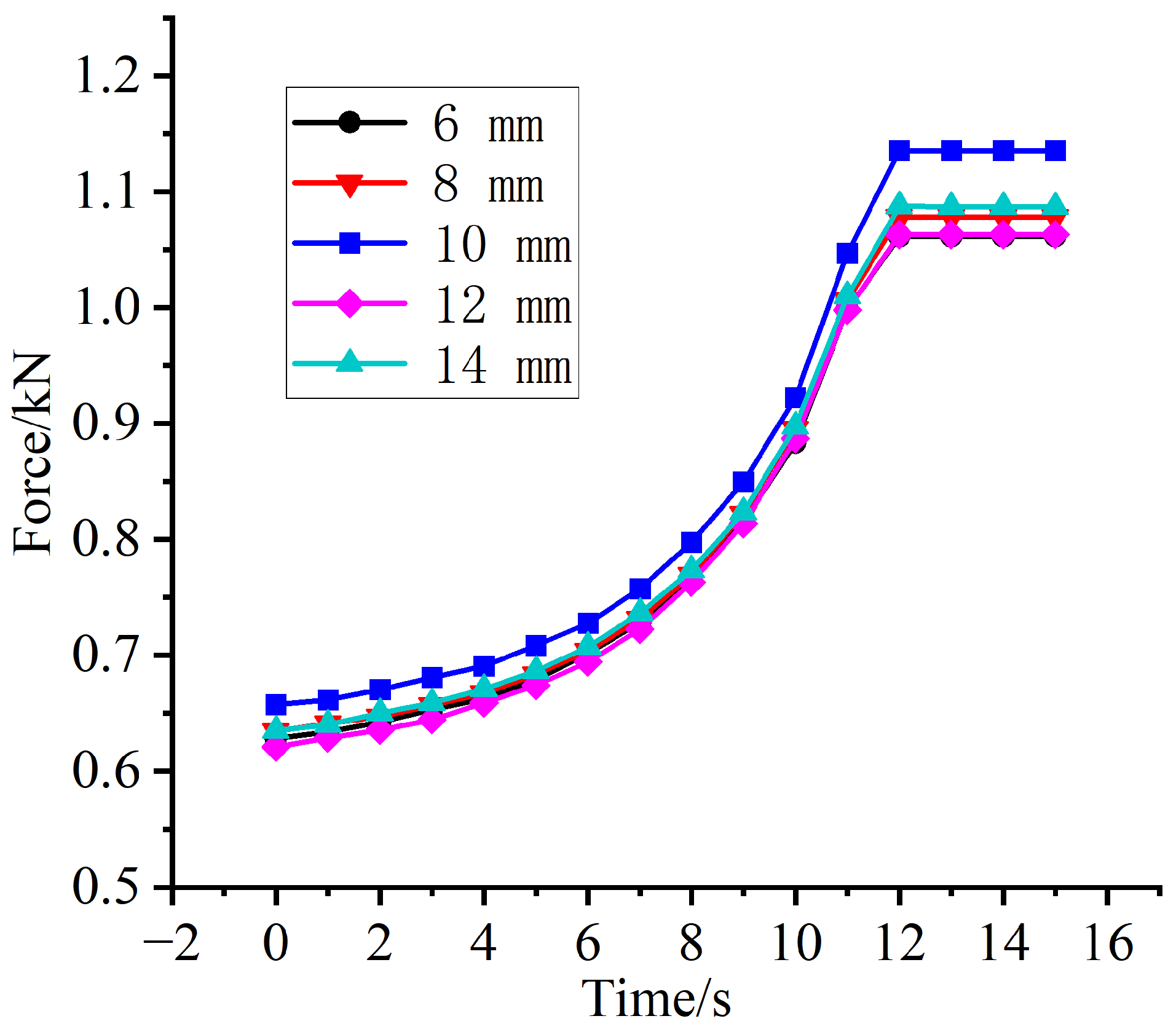
Simulations were conducted with copper sleeve thicknesses of 6 mm, 8 mm, 10 mm, 12 mm, and 14 mm, while the other key parameters remained unchanged from the initial simulation settings.
As shown in Figure 6, the simulation results indicate that as the thickness of the copper sleeve increases from 6 mm to 10 mm, the maximum repulsive force generated by the permanent magnet gradually increases. But when the thickness of the copper sleeve increases from 10 mm to 14 mm, due to the skin effect, the magnetic force between the two magnetic fields will be weakened, resulting in a decrease in the generated magnetic force. Therefore, the maximum magnetic force is generated when the thickness of the copper sleeve is 10 mm.

4.3. The Influence of Air Gap

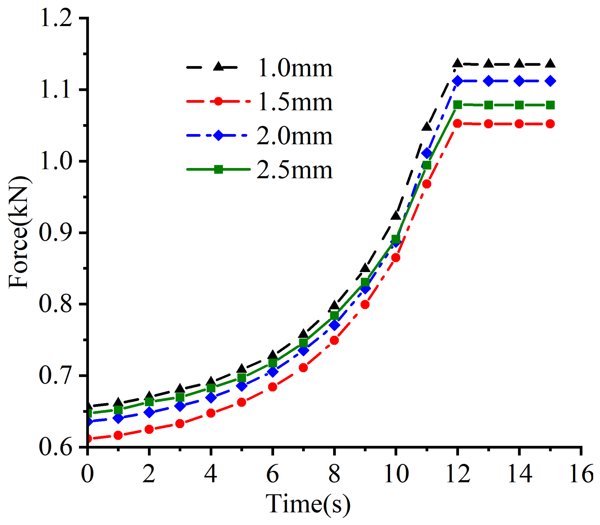
Simulation tests were performed with the gap between the upper permanent magnet and the copper sleeve set to 1.0 mm, 1.5 mm, 2.0 mm, and 2.5 mm, while the other key parameters remained unchanged from the initial simulation settings.
As shown in Figure 7, the simulation results demonstrate that as the gap between the upper permanent magnet and the copper sleeve increases from 1.0 mm to 2.5 mm, the repulsive force generated by the upper permanent magnet tends to decrease. This phenomenon is mainly due to the rapid decrease in magnetic flux density on the copper sleeve as the air gap increases, which leads to a significant decrease in the effective magnetic flux passing through the copper sleeve and a weakening of the induced eddy current intensity, thereby reducing the eddy current damping force. However, the repulsive force reaches its minimum when the air gap is 1.5 mm. This is because the magnetic field induced by the eddy currents cancels out part of the magnetic field coupled between the upper and lower permanent magnets, resulting in an extremely low magnetic flux at this air gap and thus the minimum repulsive force between the upper and lower permanent magnets.

4.4. The Influence of Relative Motion Speed of Permanent Magnets

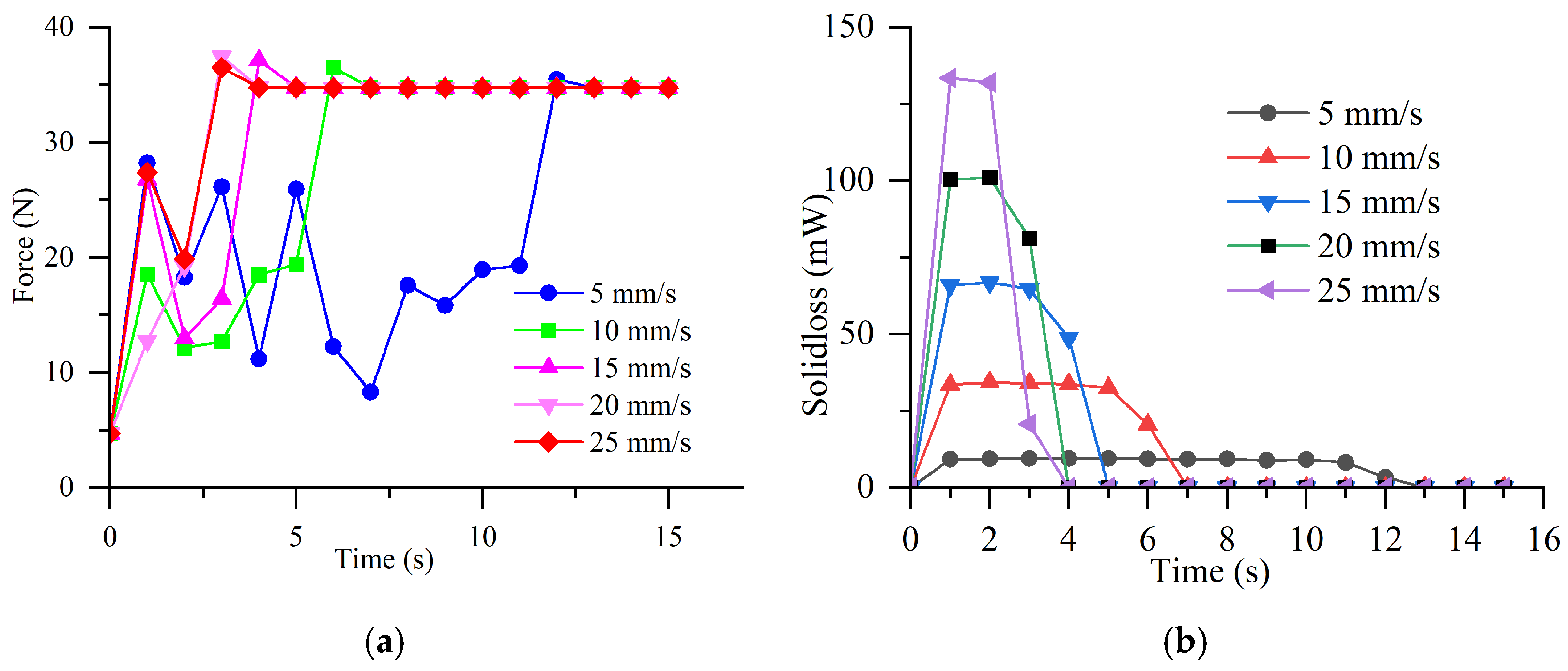
Simulation tests were conducted with the motion speed of the upper permanent magnet set at 5 mm/s, 10 mm/s, 15 mm/s, 20 mm/s, and 25 mm/s, while the other key parameters remained unchanged from the initial simulation settings.
From the previous analysis, it can be concluded that speed mainly affects the eddy current damping force. Thus, only the variations in the eddy current damping force are analyzed herein. As illustrated in Figure 8a, the simulation results demonstrate that as the speed of the upper permanent magnet increases from 5 mm/s to 25 mm/s, the eddy current damping (ECD) force increases sequentially, with a maximum value approaching 35 N. Meanwhile, as shown in Figure 8b, the solid loss induced by the eddy current damping force also increases: the loss generated at a speed of 5 mm/s is approximately 5 mW, whereas the maximum loss reaches 133 mW when the speed is 25 mm/s, and this energy dissipates to the surrounding environment in the form of thermal energy. This phenomenon is mainly attributed to the fact that an increase in speed leads to an enhancement in the rate of change of the magnetic flux passing through the copper sleeve. In accordance with Faraday’s law of electromagnetic induction, a higher rate of magnetic flux change induces a larger electromotive force (EMF), which in turn generates a stronger eddy current inside the copper sleeve. According to Lenz’s law, eddy currents induce a reverse magnetic field; consequently, the greater the eddy current damping force acting on the copper sleeve, the higher the energy loss converted into thermal energy.

5. Experimental Results and Discussion

Based on the aforementioned simulation analysis and optimization results, a prototype of a permanent magnet damper was designed and manufactured with an air gap of 1 mm, a permanent magnet thickness of 10 mm, and a copper sleeve thickness of 10 mm. The material selection for each component of the permanent magnet damper complied with the specifications presented in Table 1, which ensure the maintenance of the PMECD’s axisymmetric structural characteristics and the stability of its magnetic field distribution.
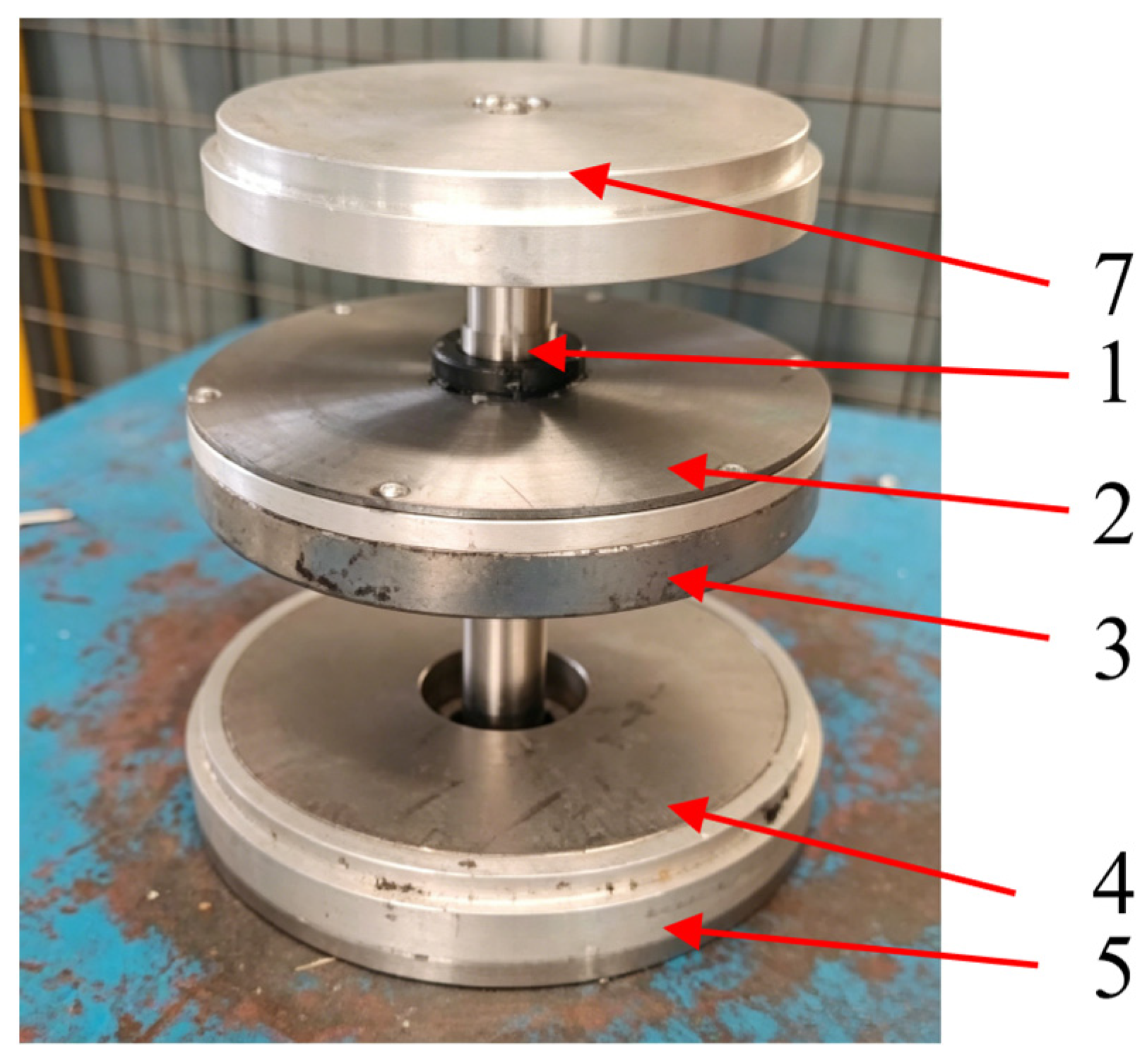
To observe the internal structure, the physical prototype of the PMECD without a copper sleeve is shown in Figure 9. It mainly consists of a central axis, an upper magnetic yoke, an upper permanent magnet, a lower permanent magnet, a lower magnetic yoke, and a load disk connected to the upper magnetic yoke.

5.1. Static Test

To test the relationship between the elastic force generated by the permanent magnet spring and the stroke distance, the weight reduction method was adopted for the experiment. A known weight load was applied to the load disk, as illustrated in Figure 9, and the added weight and the displacement between the upper and lower permanent magnets were recorded.
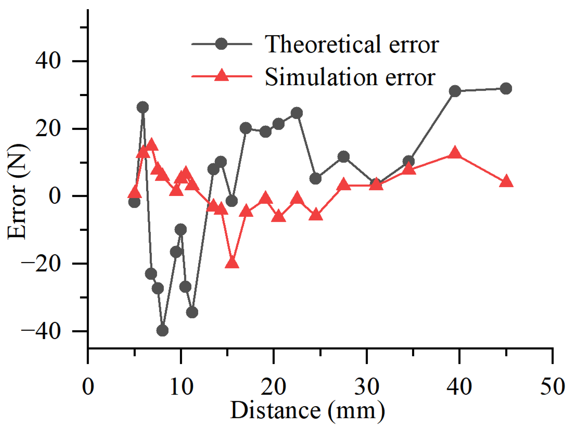
As illustrated in Figure 10, the recorded experimental data were compared with the theoretical calculation results and simulation results. The theoretical error is defined as the difference between the theoretical values and experimental values, while the simulation error is defined as the difference between the simulation results and experimental results. The results demonstrate that, compared with the experimental results, when the distance between the upper and lower permanent magnets is 5 mm, the maximum absolute values of the theoretical calculation error and simulation error are 40 N and 19 N, respectively [35]. At this displacement, the maximum load weight is approximately 880 N, resulting in relative errors of 4.5% and 2.2%, respectively. Both relative errors are less than 5%, which verifies the correctness of the proposed calculation method and established simulation model.

5.2. Dynamic Test

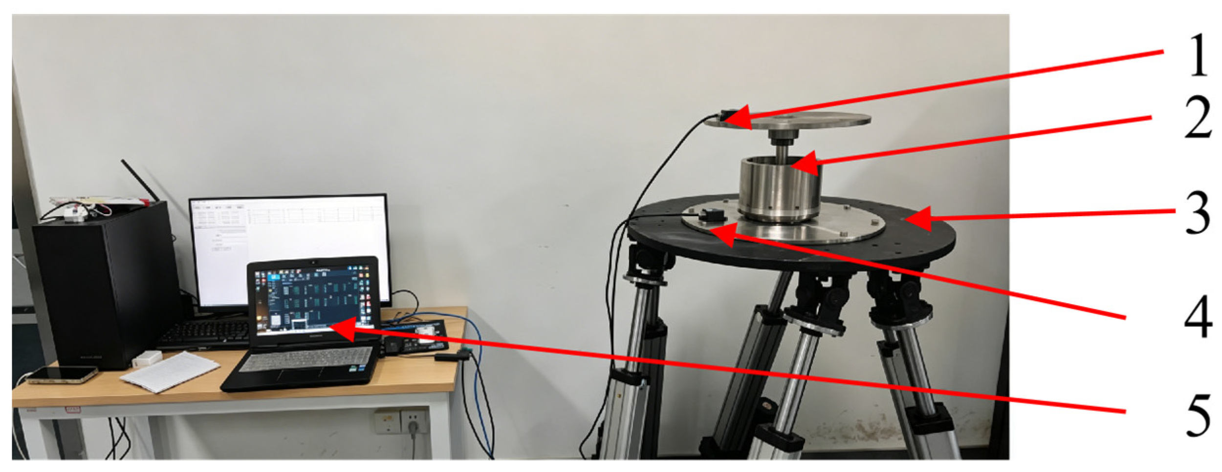
To measure the dynamic characteristics of the eddy current damper, an experimental setup was constructed as illustrated in Figure 11. The PMECD was fixed on a six-degree-of-freedom vibration platform. An acceleration sensor, A, was mounted on the tray connected to the upper permanent magnet, and an acceleration sensor, B, was mounted on the lower permanent magnet fixed to the six-degree-of-freedom workbench. The data measured by the sensor were displayed on the human–computer interaction interface via a 485 signal.
To characterize the damping characteristics of the PMECD under dynamic conditions, the method of calculating the equivalent damping ratio using acceleration transfer efficiency was adopted [36,37,38,39]. At a constant frequency, f , the acceleration transfer efficiency, T a ( f ) , at this frequency was calculated using the acceleration values measured by Accelerometer A and Accelerometer B (denoted as a up ( f ) and a down ( f ) , respectively).
T a ( f ) = a up ( f ) a down ( f ) × 100 %
Subsequently, based on the acceleration transfer efficiency values obtained at different frequencies, the maximum value, T a max ( f ) , was selected to calculate the equivalent damping ratio, ξ .
ξ = 1 2 T a max 2 ( f ) 1
The sinusoidal excitation frequencies output by the six-degree-of-freedom vibration platform were set to: 0.5 Hz, 0.6 Hz, 0.8 Hz, 1.0 Hz, 1.3 Hz, 1.6 Hz, 2.0 Hz, 2.5 Hz, 3.2 Hz, 4.0 Hz, 5.0 Hz, 6.3 Hz, 8.0 Hz, and 10.0 Hz.
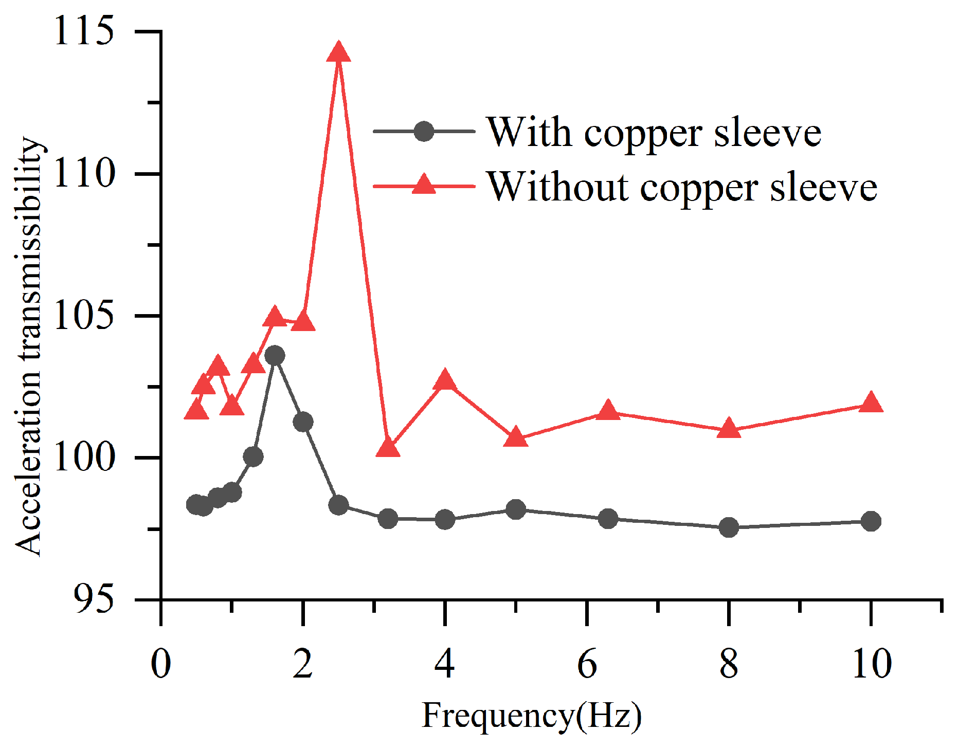
Based on the above-set vibration frequencies, experiments were conducted on the PMECD with and without a copper sleeve. The curves of acceleration transfer efficiency as a function of frequency obtained from the experiments are illustrated in Figure 12. The results demonstrate that the copper sleeve significantly reduces the acceleration transfer efficiency, which enables it to resist shocks and dissipate energy. For the PMECD with and without a copper sleeve, the equivalent damping ratios of the two configurations were calculated as 1.8454 and 0.9060, respectively. By combining these results with Equation (22), it was indicated that the damping ratio of the PMECD with a copper sleeve increased by 103.7% compared with that without a copper sleeve.

6. Conclusions

This study proposes a PMECD with an axisymmetric structure for application in automotive vibration reduction systems. Different from conventional active dampers requiring an external energy supply and traditional hydraulic dampers with oil leakage risks, the proposed PMECD is a fully passive damping device that relies on magnetic repulsion and eddy current effects. Through mathematical simulation and experimental analysis, the following conclusions are drawn:
Mathematical models for the repulsive force and eddy current damping force of permanent magnets have been established.
Simulation results demonstrate that the magnetic induction intensity is mainly concentrated on the permanent magnets and the adjacent copper sleeve, where the eddy current magnitude generated on the copper sleeve reaches its maximum. This confinement ensures that the magnetic field is restricted within a closed space and mitigates magnetic leakage. The thicker the permanent magnet, the greater the magnetic force it generates, and there exists a nonlinear relationship between the magnetic force and displacement. In contrast, the magnetic force generated increases with the thickness of the copper sleeve, exhibiting a trend of first increasing and then decreasing. With the increase in the air gap, its impact on the magnetic force presents a variation trend of first decreasing, then increasing, and finally decreasing again. Although the increase in speed leads to little change in the magnetic force, the eddy current damping force gradually increases, which in turn results in an increase in solid losses.
Comparative experimental tests further validate that the equipped copper sleeve can significantly improve the vibration damping capacity of the damper, verifying the effectiveness of the proposed structural design.
However, when the vibration frequency of the PMECD is high, a large amount of heat is easily generated, and the performance of permanent magnet materials is easily affected by temperature, thereby limiting the performance of the PMECD. Therefore, in order to further study the vibration reduction performance of the PMECD, subsequent research will focus on three specific aspects: vibration testing under random actual road excitation to adapt to real vehicle operating conditions; assessment of the irreversible demagnetization risk of permanent magnets under alternating dynamic loads; and optimization of the parameters of the PMECD based on experimental results.

Author Contributions

Conceptualization and supervision, H.W. and M.X.; Investigation, L.L.; Data curation and software, H.W. and Z.Z.; Writing—original draft preparation, H.W. and Z.Z.; Methodology, H.W.; Writing—review and editing, M.X. and X.W.; Project administration, H.W.; Funding acquisition, M.X. All authors have read and agreed to the published version of the manuscript.

Funding

This research was funded by the 2024 Anhui Province Postdoctoral Research Project (2024C976), the Key Project of Excellent Young Teacher Cultivation in 2024 (YQZD2024018), the Industrial Collaborative Innovation Special Fund Project of Anhui Polytechnic University & Jiujiang District (2022cyxtb8), the Anhui Intelligent Mine Technology and Equipment Engineering Research Center (AIMTEEL202201), the Open Fund Project of Anhui Province Joint Construction Discipline Key Laboratory for Quality and Reliability of Intelligent Equipment (IEQRKL2409 and IEQRKL2404), the Anhui Province Key Laboratory of Advanced Numerical Control & Servo Technology (No. XJSK202506), the Start-up Fund for Scientific Research (No. 2021YQQ028), and the Horizontal project (No. HX-2025-03-035).

Data Availability Statement

The datasets generated and supporting the findings of this article are obtainable from the corresponding authors upon reasonable request.

Conflicts of Interest

Xiangdong Wang was employed by Wuhu Magnetic Wheel Transmission Technology Co., Ltd. The remaining authors declare that the research was conducted in the absence of any commercial or financial relationships that could be construed as a potential conflict of interest.

References

  1. Cheng, Z.; Ma, R.; Wang, Z.; Du, X.; Bi, K. Effectiveness of a novel magnetic negative stiffness eddy-current damper for multi-mode vibration control of stay cables: Experimental and numerical investigations. Eng. Struct. 2026, 346, 121582. [Google Scholar] [CrossRef]
  2. Brun, M.; Cortes, F.; Elejabarrieta, M.J. Numerical analysis of energy dissipation due to eddy currents in a vibrating beam. J. Sound Vib. 2025, 595, 118787. [Google Scholar] [CrossRef]
  3. Simonelli, C.; Sani, L.; Gori, N.; Fernández, M.; Rizzo, R. Experimental Validation of a Permanent Magnets Magnetorheological Device under a Standardized Worldwide Harmonized Light-Duty Test Cycle. Actuators 2023, 12, 375. [Google Scholar] [CrossRef]
  4. Zhao, J.; Guo, H.; Wang, L.; Han, M. Finite-element analysis combined with an ensemble Gaussian process regression to predict the damper eddy current losses in a large turbo-generator. IET Sci. Meas. Technol. 2020, 14, 446–453. [Google Scholar] [CrossRef]
  5. Abdo, T.M.; Huzayyin, A.A.; Abdallah, A.A.; Adly, A.A. Characteristics and Analysis of an Eddy Current Shock Absorber Damper Using Finite Element Analysis. Actuators 2019, 8, 77. [Google Scholar] [CrossRef]
  6. Guo, Z.; Zhou, D.; Chen, Q.; Yu, P.; Li, J. Design and Analysis of a Plate Type Electrodynamic Suspension Structure for Ground High Speed Systems. Symmetry 2019, 11, 1117. [Google Scholar] [CrossRef]
  7. Chen, X.; Li, C.; Han, Y.; Yuan, B.; Li, K. Semiactive control for multi-mode vibration of stay cables based on electromagnetic eddy current inertia mass damper. Structures 2025, 81, 110309. [Google Scholar] [CrossRef]
  8. Yang, Z.; Liu, J.; Yang, S.; Zhang, C. Study on Electric Power Fittings Identification Method for Snake Inspection Robot Based on Non-Contact Inductive Coils. Sensors 2025, 25, 3562. [Google Scholar] [CrossRef] [PubMed]
  9. He, W.; Zhou, Y.; Zeng, W.; Li, D.; Xu, H.; Zhang, Q. Shaking table test and performance evaluation of spring eddy-current tuned mass damper. Structures 2025, 76, 109053. [Google Scholar] [CrossRef]
  10. He, Y.; Liang, H.; Lu, Y.; Xie, W.; Yan, Y.; Zhang, Z.; Liu, J.; Yang, J. Design and validation of a semi-active control system for a novel dual excitation eddy current damper. Structures 2025, 74, 108537. [Google Scholar] [CrossRef]
  11. He, Y.; Xie, W.; Lu, Y.; Liang, H.; Yan, Y.; Zhang, Z. Theoretical and experimental performance analysis of a novel rotating hybrid excitation eddy current damper. Eng. Struct. 2025, 333, 120161. [Google Scholar] [CrossRef]
  12. Liu, Z.; Wang, C.; Zhang, D. Study on Vibration Control of Wind Turbine with an Optimised Eddy Current Tuned Rolling Cylinder Damper. Struct. Control Health Monit. 2025, 2025, 67260231. [Google Scholar] [CrossRef]
  13. Lu, L.; Wang, Y.; Di, G. A Study on the Performance of a New Type of Eddy Current Damper with Inserted Magnetic Iron Rods. J. Vib. Eng. Technol. 2025, 13, 3786. [Google Scholar] [CrossRef]
  14. Song, J.; Li, H.; Zhang, H.; Fu, X. Experimental investigation and analysis of a novel multidimensional eddy current tuned mass damper for structural vibration control. J. Build. Eng. 2025, 113, 114114. [Google Scholar] [CrossRef]
  15. Umekawa, Y.; Heya, A.; Nakamura, S.; Inoue, T. Dynamic Analysis and Experimental Verification of a Multi-Degree-of-Freedom Eddy Current Damper in a Cryogenic Environment. IEEE Access 2025, 13, 104201–104219. [Google Scholar] [CrossRef]
  16. Wang, L.; Zhou, Y. Bi-directional adaptive eddy current pendulum tuned mass damper for structural nonlinear seismic response control. J. Build. Eng. 2025, 99, 111455. [Google Scholar] [CrossRef]
  17. Wu, S.; Zhou, X.; Xu, H.; Mu, P. Structural Design and Vibration Suppression Characteristics Analysis of Semi-Active Eddy Current Damping Seat. Appl. Sci. 2025, 15, 1811. [Google Scholar] [CrossRef]
  18. Liu, H.; Fu, X.; Li, H.; Liu, F. Development and Application of a Dynamic Theoretical Model for the Eddy Current Dampers Based on Mechanical Experiment. Struct. Control Health Monit. 2025, 2025, 10639911. [Google Scholar] [CrossRef]
  19. Jimenez, E.D.; Rizzo, R.; Garci, M.J.G.; Abad, E.C. Review of Passive Electromagnetic Devices for Vibration Damping and Isolation. Shock Vib. 2019, 2019, 1250707. [Google Scholar] [CrossRef]
  20. Sodano, H.A.; Bae, J.; Inman, D.J. Concept and model of eddy current damper for vibration suppression of a beam. J. Sound Vib. 2005, 288, 1177–1196. [Google Scholar] [CrossRef]
  21. Ebrahimi, B.; Khamesee, M.B.; Golnaraghi, F. Permanent magnet configuration in design of an eddy current damper. Microsyst. Technol. 2009, 16, 19–24. [Google Scholar] [CrossRef]
  22. Ebrahimi, B.; Bolandhemmat, H.; Khamesee, M.B.; Golnaraghi, F. A hybrid electromagnetic shock absorber for active vehicle suspension systems. Veh. Syst. Dyn. 2011, 49, 311–332. [Google Scholar] [CrossRef]
  23. Bae, J.; Hwang, J.; Park, J. Modeling and experiments on eddy current damping caused by a permanent magnet in a conductive tube. J. Mech. Sci. Technol. 2009, 23, 3024–3035. [Google Scholar] [CrossRef]
  24. Jimenez, E.D.; Alen-Cordero, C.; Alcover-Sánchez, R. Modelling and Test of an Integrated Magnetic Spring-Eddy Current Damper for Space Applications. Actuators 2021, 10, 8. [Google Scholar] [CrossRef]
  25. Gori, N.; Simonelli, C.; Musolino, A. Design and Optimization of a Permanent Magnet-Based Spring–Damper System. Actuators 2023, 12, 291. [Google Scholar] [CrossRef]
  26. Fu, S.; Chi, M.; Shu, A. Dynamic Study on a Passive Damping Scheme for Permanent Magnet Electrodynamic Suspension Vehicle Utilizing Onboard Magnets End Effects. Actuators 2025, 14, 344. [Google Scholar] [CrossRef]
  27. Yang, Y.; Xu, Z.; Xu, J. Experimental Investigations on Mechanical Properties and Cantilever Structure Vibration Mitigation Performance of a Rotationally Tunable Permanent Magnet MR Damper. Int. J. Struct. Stab. Dyn. 2026, 2750365. [Google Scholar] [CrossRef]
  28. Chen, T.; Li, D.; Ma, W.; Yang, Y. Design of a composite viscous damper and application on cylindrical thin-walled part milling. Proc. Inst. Mech. Eng. Part B 2023, 237, 134–143. [Google Scholar] [CrossRef]
  29. Bong-Do, P.; Jong-Hyuk, K.; Jae-Sung, B. A Study on Vibration Attenuation of Structure Applied on Eddy Current Damper. Int. J. Aeronaut. Space Sci. 2022, 23, 906–915. [Google Scholar] [CrossRef]
  30. Ge, J.; Xie, X.; Sun, Q.; Yang, G. Design and dynamic characteristics of a double-layer permanent-magnet buffer under intensive impact load. J. Sound Vib. 2021, 506, 116158. [Google Scholar] [CrossRef]
  31. Ye, L.Z.; Liu, Y.M.; Cao, M.G.; Li, D.S. Braking Characteristics and Experiment of a Permanent Magnet Eddy-current retarder. J. Beijing Univ. Technol. 2018, 44, 837–842. [Google Scholar] [CrossRef]
  32. Liu, Y.Q. Research on Composite Buffering Characteristics of Permanent Magnet-Structure Hydraulic Cylinder Based on Halbach Array. Master’s Thesis, Kunming University of Science and Technology, Kunming, China, 2019. [Google Scholar] [CrossRef]
  33. Zhao, F.T.; Wang, S.W. Calculation of force acting between permanent magnets(PM). J. Jilin Inst. Technol. 1991, 12, 9–13. [Google Scholar] [CrossRef]
  34. Lai, X.G.; Zhao, F.T. Calculation of Magnetic Circuit with Force Feedback Characteristics. J. Jilin Inst. Technol. 1991, 12, 17–21. [Google Scholar] [CrossRef]
  35. Zhang, Z.T. Research on the Design and Application of New Magnetic Springs. Master’s Thesis, Anhui Polytechnic University, Wuhu, China, 2024. [Google Scholar] [CrossRef]
  36. Li, S.; Yang, T.; Qin, X.; Li, H.; Liu, J.; Zhao, Q. Vibration control of boring bar in variable-parameter turning process with stiffness and damping adaptive TMD. Int. J. Adv. Manuf. Technol. 2025, 139, 5953–5967. [Google Scholar] [CrossRef]
  37. Xu, M.; Tian, X.T.; Chen, S.; Wang, X.; Wang, H. Design and performance optimization of a halbach-array-based permanent magnet shock absorber. Eng. Res. Express 2025, 7, 35587. [Google Scholar] [CrossRef]
  38. Shobhana, B.B.; Panchal, V.R.; Matsagar, V.A. Research Developments of Eddy Current Dampers for Seismic Vibration Control of Structures. J. Vib. Eng. Technol. 2024, 12, 5953–5971. [Google Scholar] [CrossRef]
  39. JB/T 13513-2018; Bench Test Methods of Cylindrical Shock Absorber for Low-Speed Vehicles. MIIT: Beijing, China, 2018.
Figure 1. (a) Composition and working principle diagram of PMECD; (b) layout of permanent magnetic material on the upper permanent magnet. 1—central axis; 2—upper magnetic yoke; 3—upper permanent magnet; 4—lower permanent magnet; 5—lower magnetic yoke; 6—copper sleeve.
Symmetry 18 01159 g001
Figure 2. (a) Cylindrical model; (b) circular magnetic circuit; (c) PMECD model, the arrows indicate the direction of magnetic field lines entering and exiting the copper sleeve.
Symmetry 18 01159 g002
Figure 3. Field analysis results. (a) Flux lines contour; (b) magnetic flux density contour.
Symmetry 18 01159 g003
Figure 4. Field analysis results. (a) Magnetic flux density vector contour, the arrow indicates the direction of vector B; (b) current density vector contour, the arrow indicates the direction of the instantaneous vortex flow.
Symmetry 18 01159 g004
Figure 5. The influence of permanent magnet thickness.
Symmetry 18 01159 g005
Figure 6. The influence of copper sleeve thickness.
Symmetry 18 01159 g006
Figure 7. The influence of the air gap.
Symmetry 18 01159 g007
Figure 8. The influence of speed on eddy current damping force. (a) Eddy current damping force on a copper sleeve; (b) solid loss.
Symmetry 18 01159 g008
Figure 9. Magnetic levitation spring experimental. 1—central axis; 2—upper magnetic yoke; 3—upper permanent magnet; 4—lower permanent magnet; 5—lower magnetic yoke; 7—load disk.
Symmetry 18 01159 g009
Figure 10. Relationship between force error and displacement.
Symmetry 18 01159 g010
Figure 11. Experiment on a six-degree-of-freedom vibration platform. 1. accelerometer A (model: HWT-901B, RS485, Shenzhen Weite Intelligent Technology Co., Ltd, Shenzhen City, China); 2. PMECD; 3. six-degree-of-freedom vibration platform (Wuxi Yankong Intelligent Technology, Wuxi City, China); 4. accelerometer B (model: HWT-901B, RS485, Shenzhen Weite Intelligent Technology Co., Ltd, Shenzhen City, China); 5. human–computer interaction interface.
Symmetry 18 01159 g011
Figure 12. Acceleration transfer rate test curve.
Symmetry 18 01159 g012
Table 1. Material parameters.
NameMaterialDensity (g/cm3)Remark
Central axisStainless steel AISI 3047.93 μ r ≈ 1.00
Magnetic yokeQ235-A7.85σ = 2,000,000 (S/m)
Copper sleeveCopper8.8σ = 58,000,000 (S/m)
Permanent magnetsNdFeB527.55Br ≈ 1.45 (tesla)
Table 2. Dimensional parameters.
NameSize/mmNameSize/mm
r 1 30h10
r 2 75H70
r 3 76L60
r 4 86
Disclaimer/Publisher’s Note: The statements, opinions and data contained in all publications are solely those of the individual author(s) and contributor(s) and not of MDPI and/or the editor(s). MDPI and/or the editor(s) disclaim responsibility for any injury to people or property resulting from any ideas, methods, instructions or products referred to in the content.