Article

Broadband Near-Perfect Absorption at Low Frequencies by Coupling Coiled-up Structures
1
Department of Vehicle Engineering, School of Automotive and Traffic Engineering, Jiangsu University, Zhenjiang 212013, China
2
College of Automobile and Traffic Engineering, Nanjing Forestry University, Nanjing 210037, China
3
School of Mechanical Engineering, Southeast University, Nanjing 211189, China
*
Author to whom correspondence should be addressed.
Symmetry 2026, 18(6), 927; https://doi.org/10.3390/sym18060927 (registering DOI)
Submission received: 6 May 2026 / Revised: 22 May 2026 / Accepted: 27 May 2026 / Published: 29 May 2026

Abstract

Broadband sound absorption in the low-frequency range remains a significant challenge in acoustics. Traditional sound-absorbing structures are constrained by bulky volumes, while acoustic metamaterials often involve complicated structural designs. In this work, we propose an acoustic metasurface by coupling multiple coiled-up structures, in order to achieve broadband near-perfect absorption in the low-frequency range. Capitalizing on complex frequency plane analysis, each coiled-up unit is tuned to critical damping, enabling perfect sound absorption. Through an interleaved arrangement of four coiled-up units with distinct parameters, the proposed metasurface achieves near-perfect absorption α > 0.9 within 261~372 Hz. The total thickness of the structure is 50 mm, corresponding to 1/26 of the wavelength at the lowest absorption frequency. Theoretical and simulated results confirm that sound waves at respective resonant frequencies can be captured and dissipated by the corresponding coiled-up units. Impedance tube experiments validate the accuracy of the adopted methodology, and demonstrate the potential of this metasurface for practical acoustic applications.

1. Introduction

Due to the widespread presence of low-frequency broadband noise in transportation, industry, and building environments, achieving its effective absorption remains a critical challenge in acoustics [1,2,3,4]. Traditional absorbers, such as Helmholtz resonators, generate absorption peaks through the interaction between the back cavities and neck tubes, yet suffer from narrow bandwidth. Another classical approach is porous materials, which enhance acoustic energy dissipation by leveraging microscale pores to increase the air friction. However, both structures rely on bulky volumes to achieve low-frequency absorption, which limits the practical applicability.
A promising solution lies in the acoustic metamaterials or metasurfaces [5,6,7]. Due to the artificially tunable absorption band, these absorbers can achieve subwavelength scale performance, rapidly becoming a research hotspot [8]. Numerous designs have been developed, including periodically arranged Helmholtz resonators for duct silencing [9,10,11,12], membrane metamaterials for ultra-low frequency absorption [13,14,15], and labyrinthine metasurfaces [16,17,18]. While these structures enable low-frequency absorption with compact profiles, it is still difficult to overcome the limitations of narrow bandwidth. From this perspective, the rainbow trapping effect is an exceptional design methodology [19,20]. Inspired by optical dispersion phenomena, this strategy is to capture sound waves with different frequencies at distinct spatial positions and then absorb. Thus, this kind of structure possesses excellent broadband performance, exemplified by gradient resonators [21,22,23,24] and acoustic black hole structures [25,26]. However, such designs often fail to achieve low-frequency absorption within constrained volumes. Recent efforts have focused on hybridizing these concepts to realize combined low-frequency broadband absorption [27,28,29], which shows preliminary promise and application potential.
Another effective strategy is the coiled-up structure [30]. Similar to labyrinthine metasurfaces, this approach folds the acoustic channel to effectively extend the propagation path of the sound wave [31,32]. This design transfers the vertical dimensions to lateral space, resulting in drastically reducing the structure thickness. Coiled-up structures have proven capable of subwavelength low-frequency absorption [33]. Although the friction between the air and channel wall is inherently weak, integrating porous materials or elongating the neck tubes can enhance dissipation while preserving low-frequency performance [34,35,36,37]. However, current designs often rely on multi-objective optimization for parameter matching, lacking the precise control over damping characteristics and absorption efficiency, which hinders optimal performance.
To address this, our work employs complex frequency plane analysis to design an acoustic metasurface based on coiled-up channels. This method enables assessment of system damping properties readily, allowing precise tuning for perfect absorption [38,39]. By modifying parameters of narrow apertures at the entrance, the coiled-up unit achieves perfect absorption α > 0.999 at the resonance frequency. Subsequently, multiple coiled-up units with varied parameters are integrated into an acoustic metasurface through the coplanar design. For brevity, we refer to it as MCM. This metasurface couples distinct perfect absorption peaks into a continuous absorption band at low frequency. Specifically, the proposed MCM exhibits near-perfect absorption α > 0.9 from 261 to 372 Hz, with the lowest frequency corresponding to a wavelength 26 times its structural thickness. This subwavelength high-efficiency absorption demonstrates significant potential for practical applications of MCM.
In summary, one of the purposes of this work is to exploit the capability of complex frequency plane analysis to precisely control damping, thereby achieving near-perfect sound absorption in the low-frequency range. The advantage of the proposed MCM lies in its ability to independently control the resonance frequency and dissipation, allowing multiple near-perfect absorption peaks to be interleaved and smoothly connected, resulting in a broadband near-perfect absorption in the low-frequency range. This precise tuning of damping is not achievable with conventional approaches. For example, traditional labyrinthine or Helmholtz resonators rely on multi-objective optimization to achieve impedance matching. Furthermore, broadband absorbers with rainbow trapping effect depend on large dimensions and generally cannot finely adjust the system damping. Therefore, the proposed metasurface uniquely combines damping control, a parallel-coupled compact layout, and low-frequency broadband performance.

2. Modeling

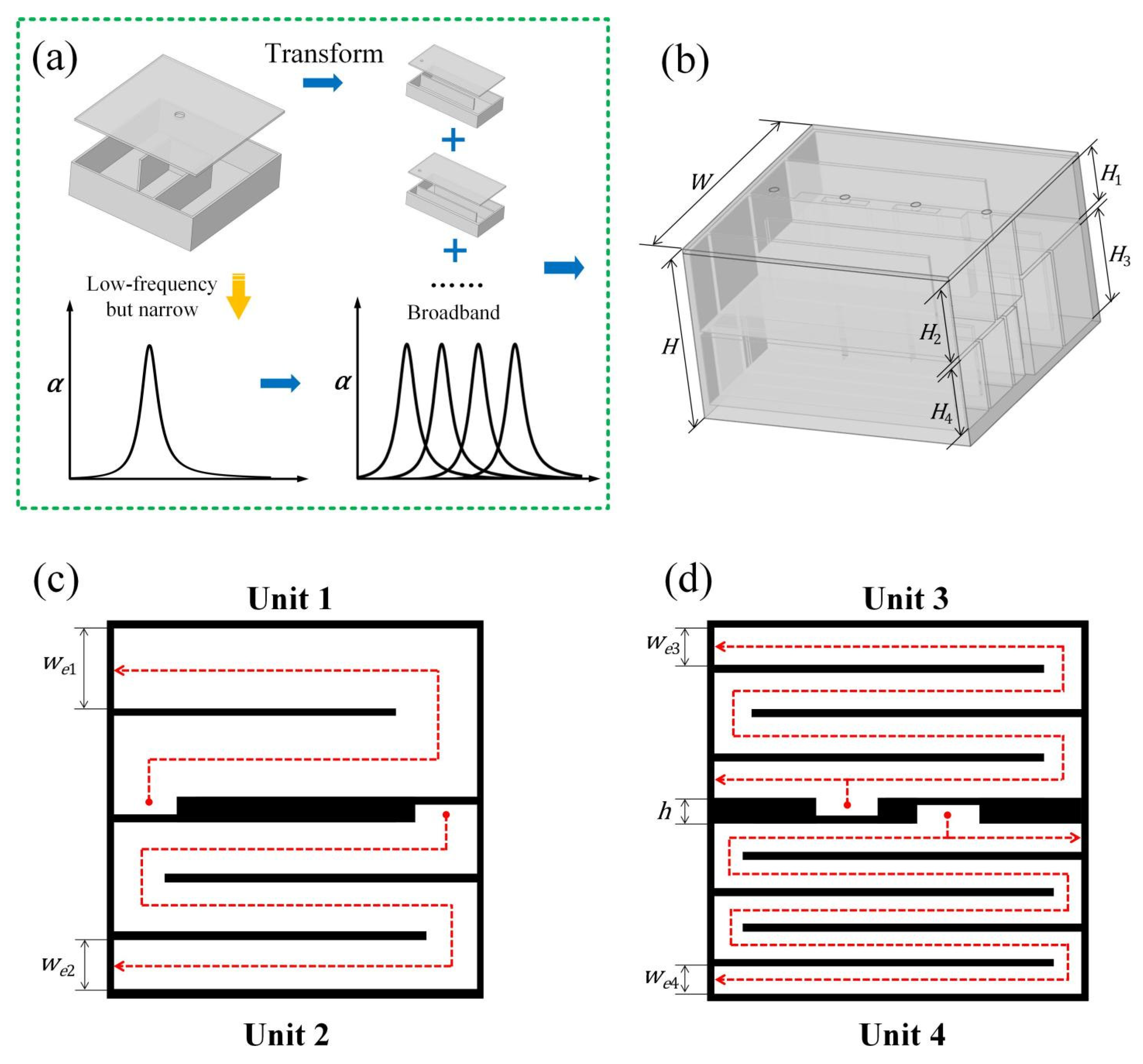
The design concept of the MCM is shown in Figure 1, and the key parameters are listed in Table 1. The top surface of the MCM is a square with side length W × W and a total thickness H . The structure comprises four coiled-up units, each with distinct thicknesses and varying numbers of baffles. Units 1 and 2 are positioned on the first layer, while Units 3 and 4 are arranged on the second layer, as shown in Figure 1c,d. Each coiled-up unit contains a number of baffles corresponding to its unit number N . Units with different thicknesses are staggered to minimize the overall structural footprint. The top surface is sealed with a perforated panel featuring four small apertures, each connected to a distinct coiled-up channel. The middle region with a height h was reserved between two units in the same layer to facilitate the sound waves to enter the coiled-up channels. All the panels in the structure are set with a thickness t = 1   m m . Acoustically, this configuration places the four coiled units in parallel. These apertures serve as the primary sources of acoustic resistance and energy dissipation, with their thermoviscous effects characterized by a complex wavenumber:
k a = k γ γ 1 Ψ t h Ψ v
where k = ω / c 0 is the wavenumber and ω = 2 π f is the angular frequency;   γ is the specific heat ratio; Ψ t h and Ψ v are the thermal and viscous field functions, which can be obtained by
Ψ t h = J 2 k t h d i 2 J 0 k t h d i 2 ,     k t h 2 = j ω ρ 0 C p κ
Ψ v = J 2 k v d i 2 J 0 k v d i 2 ,             k v 2 = j ω ρ 0 η
where j = 1 is the imaginary unit, d i is the diameter of perforated aperture for each unit, J is the Bessel function, ρ 0 is the density of the air, C p is the specific heat capacity, κ is the thermal conductivity and η is the dynamic viscosity.
Thus, the acoustic impedance of the perforated hole for unit i can be expressed as follows:
Z a , i = S 0 S a , i 2 j z 0 sin k a t 2 γ γ 1 Ψ t h Ψ v + 2 ω ρ 0 η
where S 0 = W 2 is the surface area of the metasurface, S a , i = π d i 2 / 4 is the cross-sectional area of the perforated aperture, z 0 = ρ 0 c 0 is the characteristic impedance of the air and c 0 is the sound speed.
The coiled-up channel behind the small aperture primarily provides acoustic reactance to the system, analogous to a mechanical spring. The acoustic impedance of the channel can be expressed as
Z c , i = j z c S 0 S c , i cot k c l i
where S c , i = w e , i H i is the cross-sectional area of the coiled-up channel; the w e , i and l i are its width and equivalent length respectively, which can be obtained by the following geometric relation:
w e , i = W 2 N + 1 t h 2 N
l i = N + 1 W + N + 2 t + h 2
The z c and k c in Equation (5) are the complex characteristic impedance and wavenumber of the coiled-up channel, which take the thermoviscous losses into account and can be expressed as
z c = ρ c K c ,     k c = ω ρ c K c
where ρ c and K c are the effective density and volume module, which can be obtained by
ρ c = ρ 0 1 tanh β j β j 1
K c = γ P 0 1 + γ 1 tanh β j P r β j P r 1
where β = w e , i / 2 ω ρ 0 / η ; P r = η C p / κ is the Prantle number.
Thus, the acoustic impedance of the i-th unit can be expressed as
Z i = Z a , i + Z c , i
The surface impedance of the MCM is given by the parallel formula:
Z = i = 1 4 1 Z i 1
Then, the sound reflection and absorption coefficient of the MCM can be obtained by
R = Z z 0 Z + z 0
α = 1 R 2

3. Validation by FEM and Experiment

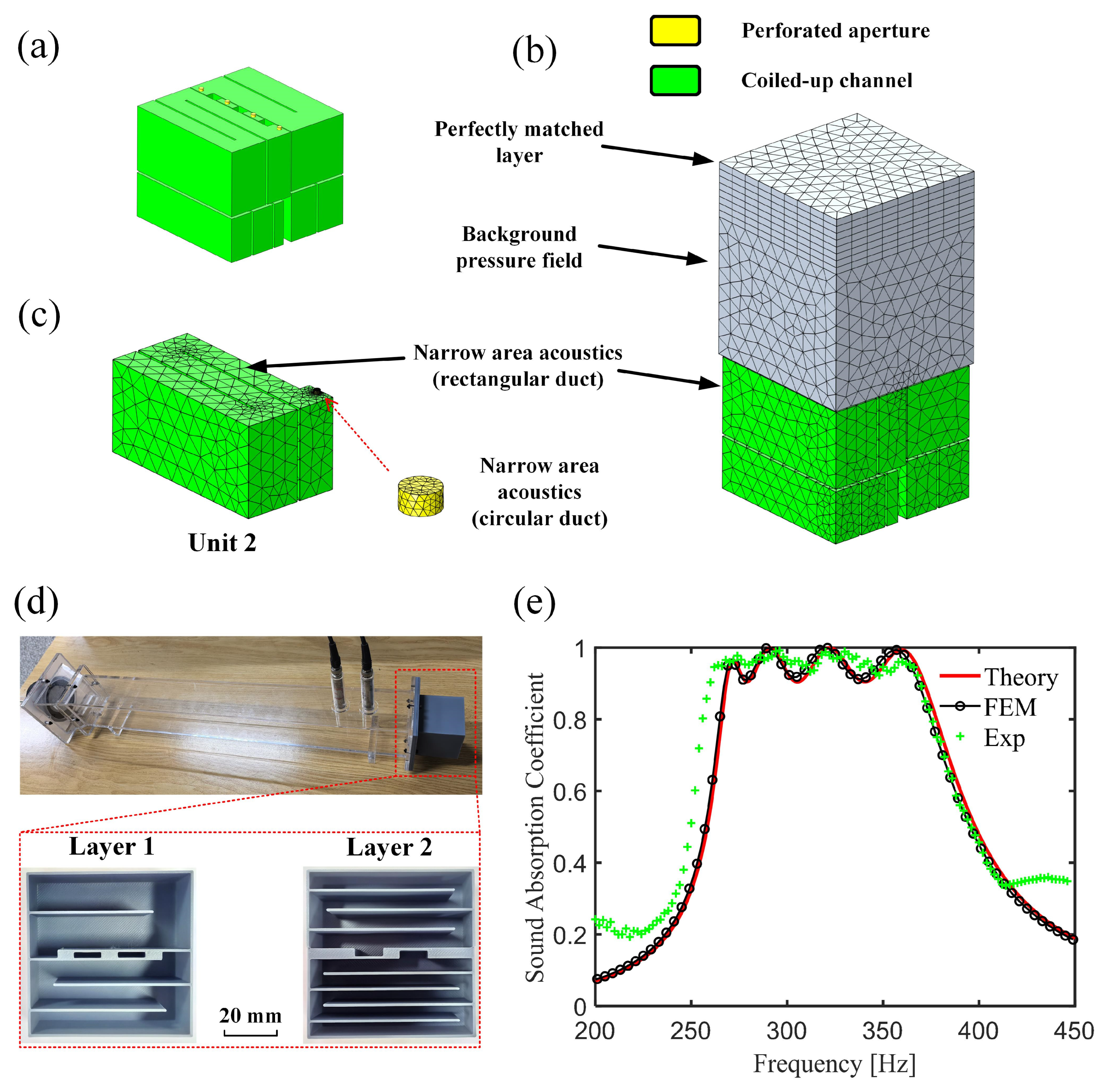
To validate the theoretical model and analyze the acoustic performance of the MCM, a finite element model is established using the Pressure Acoustics module of the commercial software COMSOL 6.2. The proposed structure possesses the parameters as follows: W = 60   m m , H 1 = 26   m m , d 1 = 1.9   m m , H 2 = 28   m m , d 2 = 2.2   m m ,   H 3 = 21   m m , d 3 = 2   m m ,   H 4 = 19   m m , and d 4 = 2.4   m m . Thus, the total thickness of the MCM is 50 mm. The finite element model is shown in Figure 2. Specifically, Figure 2a illustrates the fluid domain of the MCM, filled with air, where the perforated apertures and coiled-up channels are highlighted in yellow and green, respectively. The schematic of the finite element model is shown in Figure 2b. The top boundary of the model is set as a perfectly matched layer (PML) with a thickness of 20 mm to ensure complete absorption of reflected sound waves. Downstream of the PML is a background pressure field of 50 mm thickness, which provides a plane wave excitation with an amplitude of 1 Pa to the MCM. The MCM structure is positioned at the bottom, with its apertures and coiled-up channels simulated using the narrow area acoustics to account for thermal and viscous losses. Note the distinct cross-sectional profiles of these two regions, as indicated in Figure 2c. Since the excitation sound pressure is 1 Pa, the reflection coefficient of the MCM is obtained by averaging the scattered sound pressure in the background pressure field. The computational domain is discretized with tetrahedral elements, and the maximum element size is constrained to be less than 1/6 of the wavelength of the highest analysis frequency, while the mesh in the aperture regions is locally refined with a maximum size of 0.2 mm.
Furthermore, an impedance tube experiment is conducted to validate the adopted methodology. The impedance tube is a square waveguide with an inner side length of 60 mm. A loudspeaker positioned at the upstream end generates random white noise as excitation. The test sample is set at the downstream end, which is processed by 3D printing using resin material, as shown in Figure 2d. Two microphones are installed 60 mm and 100 mm at the front of the sample to capture sound pressure signals, and the absorption coefficient is calculated using the transfer function method. All the coiled-up units are bonded together using glue, and a perforated plate is tightly bolted to the open ends of the assembly to minimize any potential gaps within the sample. The acoustic signals are acquired by an NI cDAQ-9172 data acquisition system, and the final results are averaged over five measurements to reduce experimental uncertainties. The comparative results are presented in Figure 2e. Excellent agreement can be observed among theoretical, simulation, and experimental results. Minor deviations above 400 Hz are attributed to manufacturing tolerances. More importantly, the experimental data confirm that the proposed metasurface possesses exceptional broadband absorption performance at low frequency. Specifically, the MCM exhibits near-perfect absorption α > 0.9 across 261~372 Hz with a mere 50 mm thickness, corresponding to 1/26 of the wavelength at the lowest frequency. These results demonstrate that the proposed metasurface serves as an effective subwavelength sound absorber. Additionally, the theoretical and finite element models prove reliable for analyzing the MCM’s acoustic characteristics.

4. Results and Absorption Mechanism

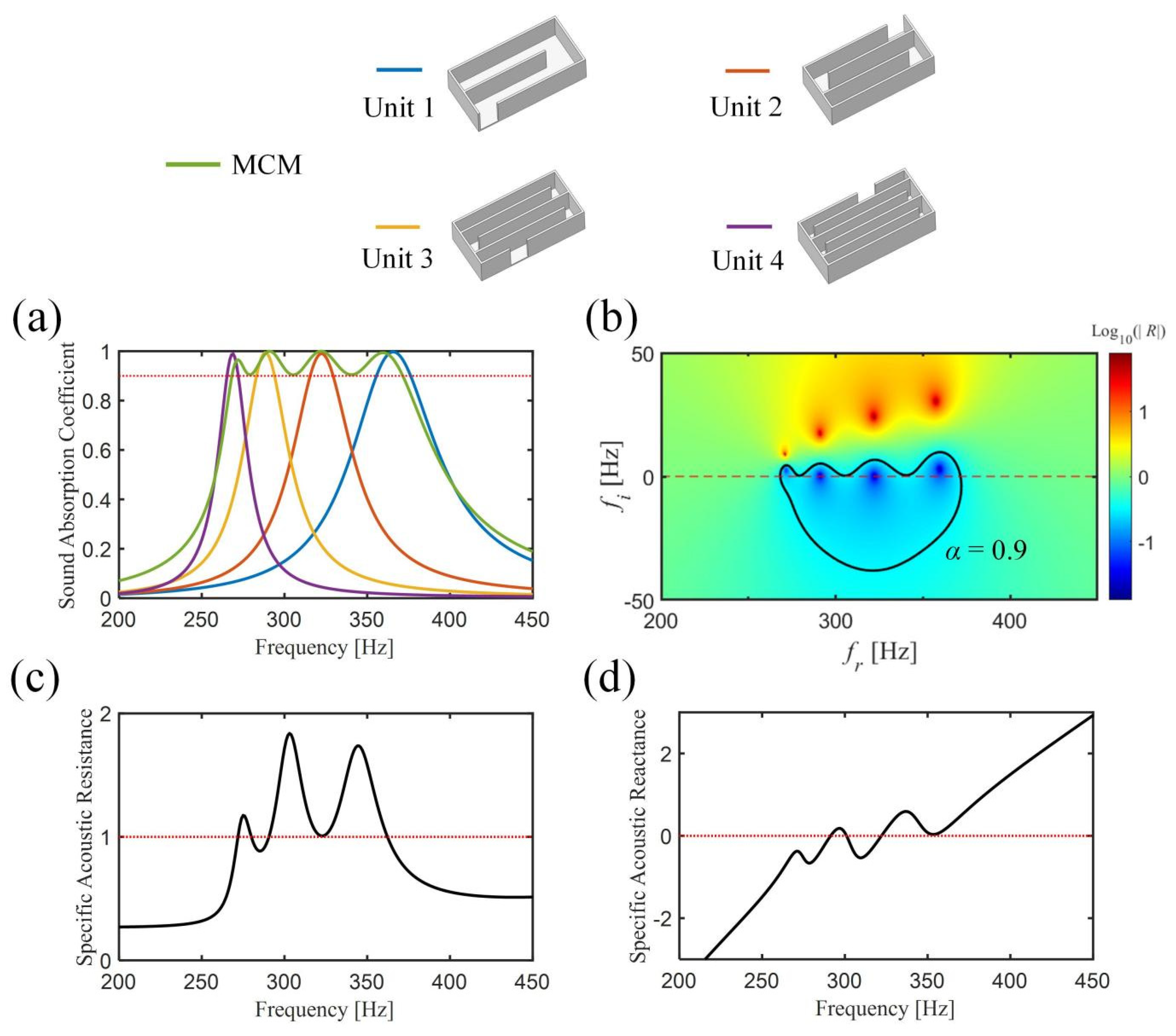
To investigate the absorption mechanism of the MCM at a fundamental level, Figure 3 reveals that its broadband performance is achieved by coupling four distinct coiled-up units. In order to investigate the acoustic characteristic, we employ the complex frequency plane analysis, where the frequency is defined as a complex variable f = f r + j f i . The principle underlying this method is that a complex frequency introduces an imaginary component to the wavenumber, which physically corresponds to energy dissipation. Thus, complex frequency plane analysis is commonly used to study the energy balance and damping behavior in acoustic systems. By defining the logarithm of the reflection coefficient as a two-dimensional function of the real and imaginary frequency components, we can generate the plot shown in Figure 3b. It can be seen that the multiple red and blue dots are clearly observed on the complex frequency plane, representing the zeros and poles of the reflection coefficient, respectively. Zeros and poles typically appear in pairs, with the real frequency component indicating the resonance frequency and the imaginary component reflecting the damping behavior. For an undamped system, zero-pole pairs would be symmetrically distributed about the real axis, meaning a pair of conjugate complex number mathematically. As the system damping increases, the zeros will shift toward the positive imaginary direction. When the zeros precisely fall on the real axis, the system will exhibit critical damping, resulting in the perfect absorption on the coefficient curve, as shown in Figure 3a. This principle is also central to the MCM design. By tuning the damping characteristic of the four coiled-up units to achieve critical coupling, with adjusting the coiled-up count and thickness to modulate resonance frequencies, the four perfect absorption peaks merge into a continuous broadband absorption band in the low-frequency range, as illustrated in Figure 3a. The detailed design process is provided in the Supplementary Materials.
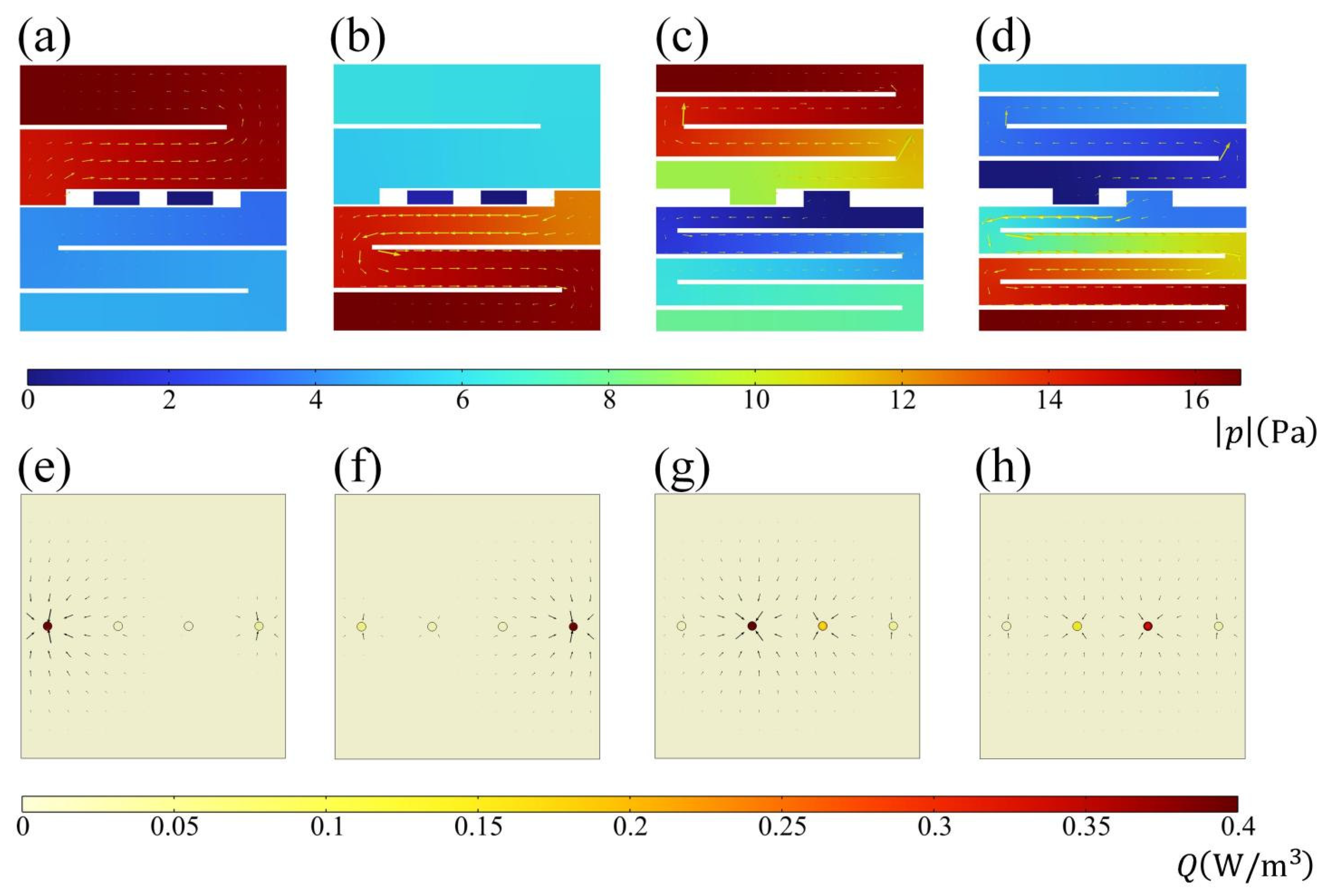
Similar conclusions can be drawn from the acoustic impedance plots (Figure 3c,d). As depicted in Equation (13), when the specific acoustic resistance reaches 1 and the specific acoustic reactance reaches 0, the system achieves perfect impedance matching. The MCM exhibits a specific acoustic resistance consistently close to 1 between 261~372 Hz, while the reactance repeatedly crosses the zero axis. This ensures sustained impedance matching across this frequency range, enabling high absorption performance. Furthermore, simulation results are also employed to validate the resonant phenomena within the MCM. Figure 4 displays the distribution of the sound pressure and energy dissipation at the four peak frequencies: 272 Hz, 291 Hz, 322 Hz, and 360 Hz. It is evident that sound waves are effectively concentrated within their respective coiled-up channels at each frequency. The arrows in the figure indicate the direction of acoustic streaming, revealing that sound waves will be guided into specific coiled-up channels depending on the frequency and subsequently dissipated through the narrow apertures at the entrances. These results confirm the presence of strong resonant behavior in the MCM. While consistent with the absorption principle of Helmholtz resonators, the coiled-up channel design outperforms conventional resonators by enabling lower-frequency absorption within an equivalent volume.

5. Conclusions

In this paper, an acoustic metasurface has been proposed for broadband absorption at low frequency, which is realized by coupling four coiled-up units with different resonance modes. Each unit has been tuned to reach critical damping behavior, achieving the perfect absorption at the resonance frequency. By arranging the four units in a staggered configuration, the distinct absorption peaks are smoothly connected across the frequency spectrum, enabling the MCM to achieve broadband high-efficiency absorption in the low-frequency range. Theoretical, simulated, and experimental results collectively demonstrate that the proposed structure attains near-perfect absorption α > 0.9 in a range of 261~372 Hz, with a bandwidth of 112 Hz. Remarkably, the total thickness of the MCM is only 50 mm, corresponding to 1/26 of the wavelength at the lowest frequency, highlighting its exceptional subwavelength performance. Furthermore, the application of complex frequency plane analysis for designing broadband absorbers constitutes a significant contribution of this work. These findings are expected to advance the design and application of acoustic metasurfaces, enabling high-efficiency, low-frequency and broadband absorption at deep subwavelength scales.
It is worth noting that the present work focuses on normal incidence, which is the standard condition for both theoretical modeling and impedance tube experiments. Due to the subwavelength thickness of the MCM, the absorption performance is expected to be weakly dependent on the incident angle up to moderate oblique angles. A systematic investigation of oblique-incidence behavior, including large angles, is planned for future research.

Supplementary Materials

The following supporting information can be downloaded at: https://www.mdpi.com/article/10.3390/sym18060927/s1. See the Supplementary Materials for detailed information on the design process of the individual coiled-up unit, and the treatment method of the entrance impedance for Unit 3 and 4.

Author Contributions

Conceptualization, Y.W. and Y.C.; Methodology, Y.W. and Y.C.; Software, Y.W. and Y.C.; Validation, Y.W.; Formal analysis, Y.W. and Y.C.; Investigation, Y.C.; Data curation, Y.C.; Writing—original draft, Y.W.; Writing—review and editing, Y.C.; Visualization, Y.W. and Y.C.; Supervision, Y.C.; Project administration, Y.C. All authors have read and agreed to the published version of the manuscript.

Funding

This work is supported by the National Natural Science Foundation of China (Grant Nos. 52275092 and 52405275) and the Natural Science Foundation of the Higher Education Institutions of Jiangsu Province, China (Grant No. 24KJB460017).

Data Availability Statement

The data that supports the findings of this study are available from the corresponding author upon reasonable request.

Conflicts of Interest

The authors declare no conflicts of interest.

References

  1. Zhao, Y.; Guo, Z.; Ye, J.; Deng, J.; Lu, X.; Zeng, K.; Wang, Z.; Li, Z. 3D Printed multilayer overlapping resonators for low-frequency broadband sound absorption: Mechanism analysis and corresponding modified theoretical method. Virtual Phys. Prototyp. 2025, 20, e2455540. [Google Scholar] [CrossRef]
  2. Guo, Z.; Du, L.; Yang, Z.; Zeng, K.; Lei, Z.; Wang, Z.; Li, Z.; Fan, Z. Switchable Bidirectional Sound Absorption Via Exceptional Point Modulation in Acoustic Metastructures with Interleaved Resonator Coupling. Adv. Sci. 2025, 12, e08951. [Google Scholar] [CrossRef] [PubMed]
  3. Ma, F.; Zhang, H.; Wang, X.; Liu, C.; Wu, J.H. Ultrathin space-shift phase-coherent cancellation metasurface for broadband sound absorption. Small Methods 2023, 7, 2300569. [Google Scholar] [CrossRef] [PubMed]
  4. Wang, B.; Zhou, W.; Zhao, Q.; Wang, H.; Zhang, Y.; Zhang, D.; Shu, F.; Yang, G.; Wu, L. Ge2Sb2Te5-Based Multifunctional Reconfigurable Terahertz Metamaterials with Joint Polarization Control. Laser Photon. Rev. 2026, 20, e02941. [Google Scholar] [CrossRef]
  5. Hao, S.; Sheng, H.; Liu, X.; Li, H.; Li, S.; Ding, Q. Low-frequency and broadband vibration absorption of a metamaterial plate with acoustic black hole resonators. Thin-Walled Struct. 2024, 202, 112073. [Google Scholar] [CrossRef]
  6. Zhou, Z.; Huang, S.; Li, D.; Zhu, J.; Li, Y. Broadband impedance modulation via non-local acoustic metamaterials. Natl. Sci. Rev. 2022, 9, nwab171. [Google Scholar] [CrossRef]
  7. Gao, Z.; Ma, Q.; Yang, J.; Shen, C.; Meng, H. Origami-based acoustic metamaterial for low-frequency adjustable sound absorption. J. Sound Vib. 2025, 618, 119334. [Google Scholar] [CrossRef]
  8. Gao, N.; Zhang, Z.; Deng, J.; Guo, X.; Cheng, B.; Hou, H. Acoustic metamaterials for noise reduction: A review. Adv. Mater. Technol. 2022, 7, 2100698. [Google Scholar] [CrossRef]
  9. Dandsena, J.; Jena, D.P. Acoustic attenuation and effective properties of single and periodic Helmholtz resonators having porous core. Appl. Acoust. 2023, 211, 109490. [Google Scholar] [CrossRef]
  10. Cai, X.; Guo, Q.; Hu, G.; Yang, J. Ultrathin low-frequency sound absorbing panels based on coplanar spiral tubes or coplanar Helmholtz resonators. Appl. Phys. Lett. 2014, 105, 121901. [Google Scholar] [CrossRef]
  11. Kim, D.; Ih, J. Wideband reduction of in-duct noise using acoustic metamaterial with serially connected resonators made with MPP and cavities. Appl. Phys. Lett. 2020, 116, 251904. [Google Scholar] [CrossRef]
  12. Liu, G.; Peng, Y.; Liu, M.; Zou, X.; Cheng, J. Broadband acoustic energy harvesting metasurface with coupled Helmholtz resonators. Appl. Phys. Lett. 2018, 113, 153503. [Google Scholar] [CrossRef]
  13. Wang, X.; Luo, X.; Zhao, H.; Huang, Z. Acoustic perfect absorption and broadband insulation achieved by double-zero metamaterials. Appl. Phys. Lett. 2018, 112, 021901. [Google Scholar] [CrossRef]
  14. Pan, H.; Zhou, K. Deformation-driven membrane-type acoustic metamaterials for tunable sound absorption: A combined experimental and numerical study. Mech. Syst. Signal Process. 2025, 237, 113002. [Google Scholar] [CrossRef]
  15. Wang, M.; Yi, K.; Kovacic, I.; Zhou, X.; Zhu, R. Ultralow-frequency absorption mechanism of a hybrid membrane resonator with acoustic soft boundary condition. J. Sound Vib. 2025, 596, 118686. [Google Scholar] [CrossRef]
  16. Huang, S.; Fang, X.; Wang, X.; Assouar, B.; Cheng, Q.; Li, Y. Acoustic perfect absorbers via spiral metasurfaces with embedded apertures. Appl. Phys. Lett. 2018, 113, 233501. [Google Scholar] [CrossRef]
  17. Li, Y.; Assouar, B.M. Acoustic metasurface-based perfect absorber with deep subwavelength thickness. Appl. Phys. Lett. 2016, 108, 063502. [Google Scholar] [CrossRef]
  18. Zhang, J.; Zeng, Q.; Hou, H.; Xiao, Y.; Cheng, B.; Xia, Z. Study of the noise reduction performance of acoustic enclosures with ultra-thin bending labyrinth metasurfaces. Appl. Acoust. 2025, 231, 110447. [Google Scholar] [CrossRef]
  19. Wu, H.; Yin, Y.; Sheng, Z.; Li, Y.; Qi, D.; Peng, R. Multiband omnidirectional ventilated acoustic barriers based on localized acoustic rainbow trapping. Phys. Rev. Appl. 2021, 15, 054033. [Google Scholar] [CrossRef]
  20. Wang, G.; Wei, Y.; Chen, Z.; Lim, C.W. Controllable subwavelength topological rainbow trapping in water-filling acoustic metamaterials. Appl. Acoust. 2023, 207, 109366. [Google Scholar] [CrossRef]
  21. Gao, Y.; Li, Z.; Liang, B.; Yang, J.; Cheng, J. Improving sound absorption via coupling modulation of resonance energy leakage and loss in ventilated metamaterials. Appl. Phys. Lett. 2022, 120, 261701. [Google Scholar] [CrossRef]
  22. Bravo, T.; Maury, C. Converging rainbow trapping silencers for broadband sound dissipation in a low-speed ducted flow. J. Sound Vib. 2024, 589, 118524. [Google Scholar] [CrossRef]
  23. Wang, Z.; Lu, X.; Guo, Z.; Li, Z.; Lei, Z.; Zeng, K.; Zhao, Y. Gradient Fabry-Pérot acoustic metamaterials enable Rainbow-Trapping enhanced broadband sound insulation. Int. J. Mech. Sci. 2025, 289, 110056. [Google Scholar] [CrossRef]
  24. Jiménez, N.; Romero-García, V.; Pagneux, V.; Groby, J. Rainbow-trapping absorbers: Broadband, perfect and asymmetric sound absorption by subwavelength panels for transmission problems. Sci. Rep. 2017, 7, 13595. [Google Scholar] [CrossRef]
  25. Mi, Y.; Zhai, W.; Cheng, L.; Xi, C.; Yu, X. Wave trapping by acoustic black hole: Simultaneous reduction of sound reflection and transmission. Appl. Phys. Lett. 2021, 118, 114101. [Google Scholar] [CrossRef]
  26. Bednarik, M.; Cervenka, M. A sonic black hole of a rectangular cross-section. Appl. Math. Model. 2024, 125, 529–543. [Google Scholar] [CrossRef]
  27. Chen, Y.; Yu, K.; Fu, Q.; Du, X.; Zhang, J.; Lu, X. Broadband and low-frequency sound absorber by a rectangular sonic black hole combined with labyrinth metasurface. Mech. Syst. Signal Process. 2025, 239, 113301. [Google Scholar] [CrossRef]
  28. Deng, J.; Guasch, O. Sound waves in continuum models of periodic sonic black holes. Mech. Syst. Signal Process. 2023, 205, 110853. [Google Scholar] [CrossRef]
  29. Mi, Y.; Cheng, L.; Zhai, W.; Yu, X. Broadband low-frequency sound attenuation in duct with embedded periodic sonic black holes. J. Sound Vib. 2022, 536, 117138. [Google Scholar] [CrossRef]
  30. Yang, J.; Lee, J.S.; Kim, Y.Y. Metaporous layer to overcome the thickness constraint for broadband sound absorption. J. Appl. Phys. 2015, 117, 174903. [Google Scholar] [CrossRef]
  31. Zhang, C.; Hu, X. Three-dimensional single-port labyrinthine acoustic metamaterial: Perfect absorption with large bandwidth and tunability. Phys. Rev. Appl. 2016, 6, 064025. [Google Scholar] [CrossRef]
  32. Yan, J.; Li, Y.; Peng, Y.; Yao, S. Acoustic metasurface embedded with thin-walled plate based on phase modulation for multi-angle broadband sound absorption. Thin-Walled Struct. 2024, 199, 111839. [Google Scholar] [CrossRef]
  33. Liang, Z.; Liu, C.; Liu, Y.; Ma, Y.; Ma, F. Demand-driven inverse design and optimization for ultra-thin broadband sound-absorbing metamaterials based on metaheuristic-enhanced autoencoder network. Compos. Part B Eng. 2025, 304, 112643. [Google Scholar] [CrossRef]
  34. Zhang, W.; Xin, F. Coiled-up structure with porous material lining for enhanced sound absorption. Int. J. Mech. Sci. 2023, 256, 108480. [Google Scholar] [CrossRef]
  35. Lu, T.; Yang, L.; Huang, C.; Zhang, G.; Tang, R.; Gu, J. Design of low-frequency acoustic metamaterials based on spiral space and porous lining. Thin-Walled Struct. 2025, 216, 113678. [Google Scholar] [CrossRef]
  36. Wang, J.; Bennett, G.J. Deep sub-wavelength broadband metasurface with micro-perforated panels and extended-neck Helmholtz resonators. Appl. Phys. Lett. 2025, 126, 141703. [Google Scholar] [CrossRef]
  37. Abrahams, M.P.; Oudich, M.; Revalor, Y.; Vukadinovic, N.; Assouar, B. Hybrid ultrathin metasurface for broadband sound absorption. Appl. Phys. Lett. 2024, 124, 151702. [Google Scholar] [CrossRef]
  38. Romero-García, V.; Theocharis, G.; Richoux, O.; Pagneux, V. Use of complex frequency plane to design broadband and sub-wavelength absorbers. J. Acoust. Soc. Am. 2016, 139, 3395–3403. [Google Scholar] [CrossRef]
  39. Huang, S.; Zhou, Z.; Li, D.; Liu, T.; Wang, X.; Zhu, J.; Li, Y. Compact broadband acoustic sink with coherently coupled weak resonances. Sci. Bull. 2020, 65, 373–379. [Google Scholar] [CrossRef]
Figure 1. Schematic diagram of the MCM: (a) The concept of the design for broadband absorption based on the coiled-up structure; (b) 3D model of the MCM; (c) the schematic of Units 1 and 2; (d) the schematic of Units 3 and 4. The red dotted lines in the figure represent the propagation path of the sound waves inside the coiled-up channels.
Symmetry 18 00927 g001
Figure 2. Validation: (a) The air domain in the MCM; (b) schematic diagram of the finite element model of the MCM; (c) detailed mesh of Unit 2; (d) impedance tube experiment and the test sample; (e) absorption coefficients obtained by the theory, simulations and experiments.
Symmetry 18 00927 g002
Figure 3. Acoustic performance of the MCM: (a) Sound absorption coefficients of the MCM and each unit; (b) Log 10 R on the complex frequency plane; (c) specific acoustic resistance of the MCM; (d) specific acoustic reactance. The blue points on the complex frequency plane represent the zeros, which characterize the damping behavior of the MCM. The zeros falling on the real axis indicate the system reaching the critical damping, which exhibits the perfect absorption in the absorption coefficient.
Symmetry 18 00927 g003
Figure 4. Acoustic resonance of the MCM: Distribution of the acoustic pressure and dissipation in (a,e) Unit 1, (b,f) Unit 2, (c,g) Unit 3 and (d,h) Unit 4. The resonance frequencies are 360, 322, 291 and 272 Hz, left to right, respectively.
Symmetry 18 00927 g004
Table 1. Key parameters of the MCM.
SymbolDescription
W Side length of metasurface
H Total thickness
N Number of baffles
t Panel thickness
h Middle gap height
H i Unit thicknesses
d i Aperture diameters
w e , i Channel width
l i Equivalent channel length
k a Complex wavenumber in aperture
k c Complex wavenumber in channel
Disclaimer/Publisher’s Note: The statements, opinions and data contained in all publications are solely those of the individual author(s) and contributor(s) and not of MDPI and/or the editor(s). MDPI and/or the editor(s) disclaim responsibility for any injury to people or property resulting from any ideas, methods, instructions or products referred to in the content.