Article

Dynamic Modeling and Characteristics of a Two-Dimensional Nonlinear Friction-Induced Slider Moving on an Oscillating Belt Based on Stick-Slip Motion

1
College of Mechanical & Electrical Engineering, Shaanxi University of Science & Technology, Xi’an 710021, China
2
School of Mechanics and Safety Engineering, Zhengzhou University, Zhengzhou 450001, China
3
Institute of Vibration Engineering, Northwestern Polytechnical University, Xi’an 710072, China
*
Author to whom correspondence should be addressed.
Symmetry 2026, 18(7), 1126; https://doi.org/10.3390/sym18071126
Submission received: 19 May 2026 / Revised: 26 June 2026 / Accepted: 29 June 2026 / Published: 1 July 2026

Abstract

The belt velocity is not strictly constant but exhibits periodic oscillations in certain industrial applications. A lumped mass model of a two-dimensional nonlinear friction-induced slider moving on an oscillating belt is established in this paper. Tangential stick-slip motion and normal separation–re-contact behavior are both considered under a symmetrically and uniformly distributed interface force. The analytical expression of the static friction force is deduced in terms of dynamic equations and stick-slip-separate state transition boundaries of the slider. The sliding friction force is modelled by a dynamic model that accounts for relative velocity. The Runge–Kutta algorithm combining the bisection method to capture the transition point between stick and slip motions is adopted to compute the vibration responses of the slider. The numerical results indicate that the belt’s oscillatory angular vibration frequency, the vertical preload, and the nonlinear stiffness have great effects on the dynamic characteristics of the slider, and the slider can experience p -periodic ( p = 1 , 2 , 3 , 4 ,   ect . ) and chaotic vibration due to the non-smooth behavior at the contact interface.

1. Introduction

Dry friction plays a dual role in mechanical systems [1]. On one hand, it serves as the fundamental mechanism enabling power transmission in critical components such as automotive disc brakes, clutches, and actuators. On the other hand, dry friction acts as a primary source of nonlinear vibrations and dynamic instabilities. Although phenomena such as stick-slip motions and friction-induced self-excited vibrations have been extensively studied, the inherent complexity of their underlying mechanisms and the persistent challenge of vibration suppression in industrial environments remain incompletely resolved.
Dry-friction-induced vibrations are widespread in engineering [2,3]; thus, they are of great interest for researchers. Dynamic models play a crucial role in the study of friction-induced vibration; they can help to reveal the physical mechanism. Two discrete and two continuous models of the stick-slip systems with rich bifurcational and chaotic behavior were investigated by Popp and Stelter [4]. Effects of damping on mode-coupling instability in friction-induced oscillations were studied using a two-degree-of-freedom minimal model [5]. As there lacks a minimal model to describe the basic behavior of the disk brake squeal, which can easily be associated with an automotive disk brake, a new minimal model of a disk brake, which takes into account the vibration of the disk, was introduced [6]. Elmaian et al. [7] proposed a slip-stick phenomenological model to improve understanding of friction-induced noises in automobiles. They considered three physical mechanisms that can produce these noises: slip-stick, sprag-slip, and mode-coupling instabilities. Li et al. [8] unveiled the nonlinear amplification effect caused by dynamic interfacial separation using a separation-recontact model. Wang et al. [9] described a new approach to study the nonlinear dynamical behaviors of a belt-driven two-coupled friction oscillator. A 4-dof nonlinear self-excited friction oscillator was established for brake squeal analysis [10]. The stochastic planar stick-slip motions were investigated using a slider-on-belt model where the coefficient of friction of the contact interface is modelled as a random field [11]. Wang et al. [12] established a longitudinal-vertical coupled dynamics model of a vehicle-track system with a disc brake system, incorporating disc-pad nonlinear friction using the Stribeck model, with parameters derived from block-on-disc tribological tests.
Stick-slip vibration is one of the significant mechanisms proposed to explain the occurrence of friction-induced self-excited vibration. Stick-slip vibration includes two motion regimes; the stick motion may appear when the relative velocity is zero between the contact surfaces, and the slip motion appears when there is relative motion between them [13,14]. Stick-slip motion is characterized by the alternating occurrence of stick and slip phases and has attracted significant interest from both academic and industrial researchers [15,16,17,18,19,20]. The slip-stick motion occurs when the static friction coefficient is greater than the kinetic coefficient of friction or the coefficient of friction decreases with relative velocity [4,7,21,22]. The discontinuity of the dry-friction-induced system, which is caused by transformation between stick and slip motions, makes this problem difficult to solve theoretically and practically. The friction-induced slip-stick phenomenon was focused on in [23,24,25,26,27]. Won et al. [28] developed a novel stick-slip criteria for a velocity-dependent friction model. Chen and Zhou [29] performed a time–frequency analysis to analyze time–frequency characteristics of friction-induced vibration. Brunetti et al. [30] proposed a Modal Absorption Index (MAI) for unstable mode selection in squeal prediction by complex eigenvalue analysis. The effect of dynamic normal force on the slip-stick vibration characteristics was studied [31]. The parameters of the Stribeck model were identified to construct a dynamic relationship between working conditions and the coefficient of friction to accurately reveal the stick-slip characteristics of a Disc–Block Friction System [32]. Using commercial brake pads in three different sizes, the size effects of brake pads on stick-slip phenomena were investigated [33]. The phenomenon of brake squeal noise generated by automotive disc brake systems was delved into through numerical analysis [34]. The stability, slip-stick bifurcation characteristics, and key factors affecting the slip-stick vibration of the disc brake system were analyzed through models simulation [35]. Convergence analysis of the numerical algorithm of the dry friction constrained system considering stick-slip motion was performed [36].
While the aforementioned studies provide deep insights into friction-induced vibrations under constant sliding speeds, in many practical engineering applications, the belt velocity is rarely perfectly constant; thus, the influence of variable velocities on dry-friction-induced vibration problems is examined. Acceleration of the disc motion on the frictional instability was investigated [37]. This phenomenon precisely indicates that the spinning speed of the disc has a significant impact on the friction-induced dynamics of the system. The friction-induced vibration of a mass–slider with in-plane and transverse springs and dampers in sliding contact with a spinning elastic disc in three different situations of spinning speed, i.e., constant deceleration, constant acceleration and constant speed, was explored by Liu and Ouyang [38].Distinct dynamic behaviors were observed under these three rotational-speed conditions. This phenomenon precisely indicates that the spinning speed of the disc has a significant impact on the friction-induced dynamics of the system.
In the existing literature, the dry-friction-induced vibration problems are usually studied by employing a constant velocity, e.g., constant belt velocity in the slider-belt model, the constant spinning speed of the disc, or linear acceleration or deceleration. However, the belt velocity may not be constant or linear variation, and often the belt translation is always in a periodically oscillating state in industry [39]. In certain industrial applications, the belt velocity is not strictly constant but exhibits periodic oscillations due to factors such as eccentric pulleys, torsional vibrations in the drivetrain, or specific servo-driven indexing tasks. And the research on the dry-friction-induced dynamics under oscillating belt translation is still quite limited. In order to examine the influence of oscillating belt translation on the dynamics of the frictional system in a more realistic model, the nonlinear friction-induced slider moving on the belt at oscillating speeds is explored in this paper.

2. The Mechanical Model

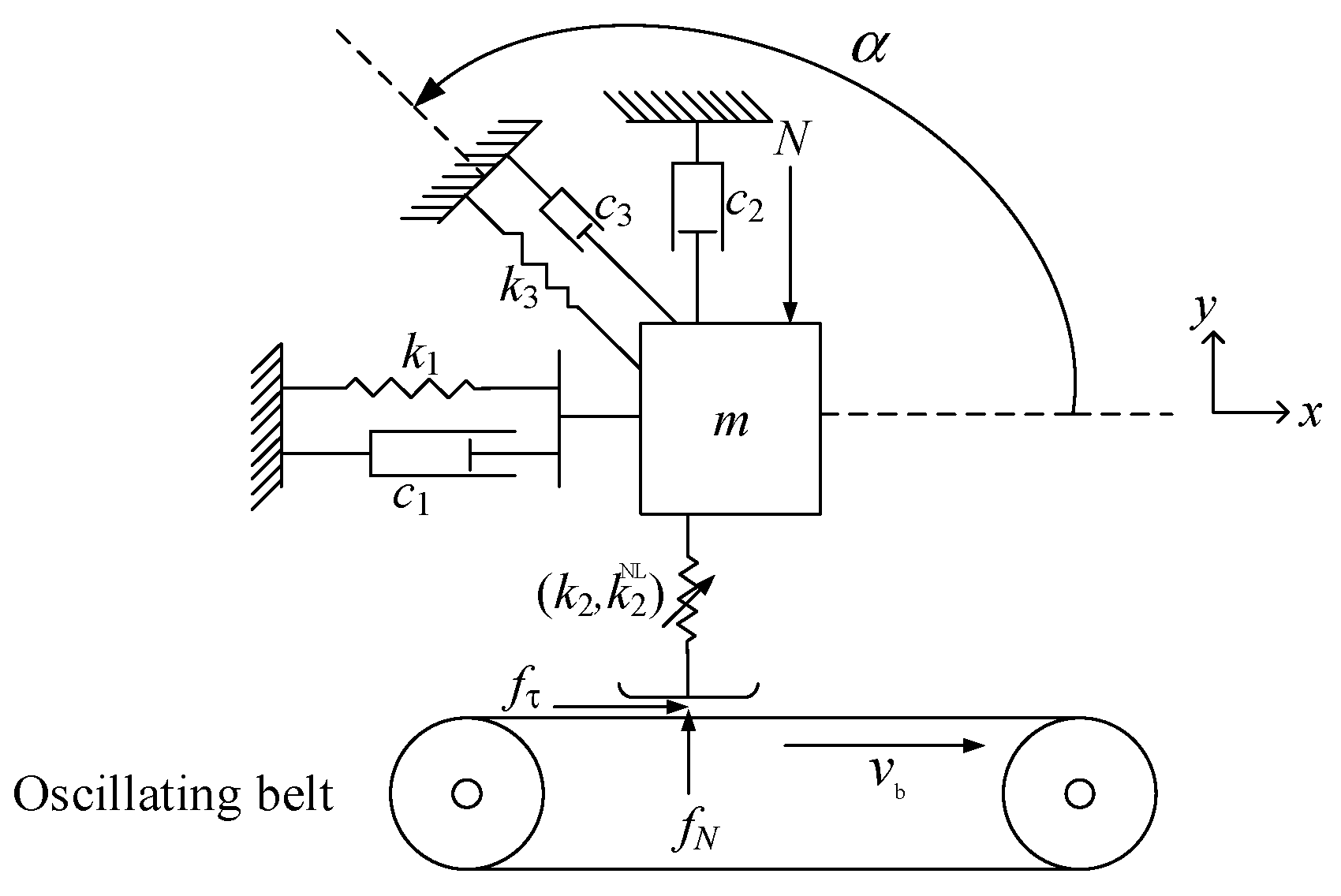
To capture and reveal the properties of the slider that is moving on an oscillating belt, a two-dimensional nonlinear friction-induced slider (2D-NLFIS) model is developed in terms of a minimal model frequently utilized to describe basic behaviors of systems like disc brakes, proposed by Hoffmann et al. [40], as shown in Figure 1. The belt surface traveling with a time varying speed v b , v b is defined here based on the work by Luo and Gegg [39], which can be written as
v b = v v sin ( ω t + φ ) + v 0
where ω is the oscillatory angular frequency of the belt, f e = ω / ( 2 π ) denotes the oscillatory frequency of the belt, and v v and v 0 are oscillatory amplitude and constant of the traveling belt surface, respectively. The slider of mass m is compressed by a vertical compression force N to bring the slider against the rigid belt moving at an oscillating speed; a linear spring k 2 and a nonlinear cubic spring k 2 NL are used to model the normal contact stiffness between the slider and the oscillating belt. The cubic nonlinear spring is selected because it is a widely accepted, minimalist mathematical representation used to capture the stiffness hardening effect commonly observed at dry friction contact interfaces. In addition, the slider is constrained by two springs k 1 , k 3 and three dampers c 1 , c 2 , c 3 . In this 2D-NLFIS model, the structural springs k 1 and k 3 constrain the slider’s macro-vibrations and represent the surrounding elastic fixtures; thus, the structural springs are represented by linear springs. The inclined spring k 3 and damper c 3 construct off-diagonal cross-coupling terms in the stiffness and damper matrices, which are physically essential to simulate mode-coupling instability—a primary cause of friction-induced vibrations. f N and f τ are the normal contact force and friction force acting on the slider, respectively. The normal contact force and friction force are both distributed symmetrically and uniformly over the whole contact surface; thus, friction can be modeled by the macro-slip model. The coordinate system x - y used in this paper is defined with its origin at the position before the vertical preload N is applied and before the springs deform.

3. Criterion for Stick-Slip-Separate Transition and the Dynamic Equations

From a practical point of view, vertical separate motion and horizontal stick-slip motion may happen between the contact surfaces. Accordingly, the equations of motion of the slider could be written as
m 0 0 m x ¨ y ¨ + c 11 c 12 c 21 c 22 x ˙ y ˙ + k 11 k 12 k 21 k 22 x y = f τ f N N
where the coefficients of the stiffness matrix and the damping matrix can be described as
k 11 = k 1 + k 3 cos 2 α k 12 = k 3 cos α sin α k 21 = k 3 sin α cos α k 22 = k 3 sin 2 α
c 11 = c 1 + c 3 cos 2 α c 12 = c 3 cos α sin α c 21 = c 3 sin α cos α c 22 = c 2 + c 3 sin 2 α
As shown in Figure 1, the normal motion of the slider will lead to the variation of the normal contact force and two stages of separate and contact states between the belt and the slider. The normal contact force f N is expressed as
f N = k 2 y k 2 NL y 3             y < 0               contact   state 0                                                         y 0               separate   state
When y > 0 , the belt and the slider are in the separate state, f N = 0 , f τ = 0 . When y 0 , the belt and the slider are in the contact state, f N = k 2 y k 2 NL y 3 . The current continuous contact model is applicable to the study of stick-slip vibration caused by friction because it belongs to the category of microscopic contact. However, this continuous contact model will fail under macroscopic large separation. The contact interface may undergo stick or slip motion due to the relative tangential motion between the belt and the slider, which is determined by the relative tangential displacement, velocity and acceleration between the belt and the slider. The relative tangential displacement between the belt and the slider can be described as
x r = x b x
Based on Equation (1), the tangential displacement of the belt can be written as
x b = v v ω cos ( ω t + φ ) + v 0 t + c 0
where c 0 is the integration constant that can be determined by the initial condition. And corresponding relative tangential velocity and acceleration between the slider and the oscillating belt could be separately written as
v r = x ˙ r = x ˙ b x ˙ = v b x ˙ = v v sin ( ω t + φ ) + v 0 x ˙
a r = x ¨ r = x ¨ b x ¨ = v ˙ b x ¨ = v v ω cos ( ω t + φ ) x ¨
An exponential dynamic friction model [28], which can consider the effect of the relative velocity, is adopted in this study, and its coefficient function is described as
μ ( v r ) = μ k + ( μ s μ k ) e λ v r
where μ k and μ s are the minimum dynamic friction coefficient and the maximum static friction coefficient, respectively, λ is the design parameter to control the decline rate of the curve, and v r is the relative tangential velocity between the contact surfaces.
According to the Coulomb friction model, the friction force f τ can be expressed as
f τ = μ ( v r ) f N                                                         v r > 0                 slip   1   state μ ( v r ) f N                                                   v r < 0                 slip   2   state   μ s f N f τ μ s f N                 v r = 0                 stick   state
As shown in Equation (11), the analytical expression of the sliding friction force is determined, but the static friction force in the stick state is between the negative maximum static friction and the maximum static friction, and its exact value needs to be defined. Next, the stick-slip state transition boundaries will be constructed and the analytical expression of the friction force in the stick state will be deduced for calculating its exact value.
(1) If v r 0 , the belt and the slider are in the slip state. In terms of Equation (11), we can obtain
f τ = μ ( v r ) f N sgn ( v r )
(2) If v r = 0 , the relative tangential displacement between the belt and the slider will remain unchanging, and, obviously, a r is also equal to zero. By denoting c r as the tangential displacement difference between the belt and the slider at the end of the previous slip phase, we can get
x r = v v ω cos ( ω t + φ ) + v 0 t + c 0 x = c r
Due to v r = 0 , x r = c r , a r = 0 , based on Equation (2), the static friction force f τ can be formulated as
f τ = m v v ω cos ( ω t + φ ) + c 11 [ v v sin ( ω t + φ ) + v 0 ] + c 12 y ˙ + k 11 [ v v ω cos ( ω t + φ ) + v 0 t + c 0 c r ] + k 12 y
If f τ μ s f N ( f τ is obtained by Equation (14)), the slider will stick relative to the belt. If f τ > μ s f N ( f τ is obtained by Equation (14)), the friction force will reverse its direction and the slider will still slip relative to the belt.

4. Numerical Investigation

As the state of the slider-belt system switches between separate and contact phases, and between stick and slip phases, this brings out difficulties in the numerical calculations. The Runge–Kutta method is used to solve the non-smooth dynamic equations in this paper. The states between the belt and the slider, including stick-slip-separate phases, are monitored at each time step. In order to improve the calculation accuracy, the dichotomous method is used to accurately capture the stick-slip-separate state transition point of the sider-belt system. The values for the coefficient of friction are determined with reference to the work in Reference [28], which is commonly used for contact between solid surfaces in dry conditions. And the main system parameter values used in the numerical examples are provided with reference to the work in Reference [41]. The values for the coefficient of friction and the main system are all listed in Table 1, and the values of other parameters are given in each sub-section.

4.1. The Sensitivity of the Solutions to the Choice of Time Step

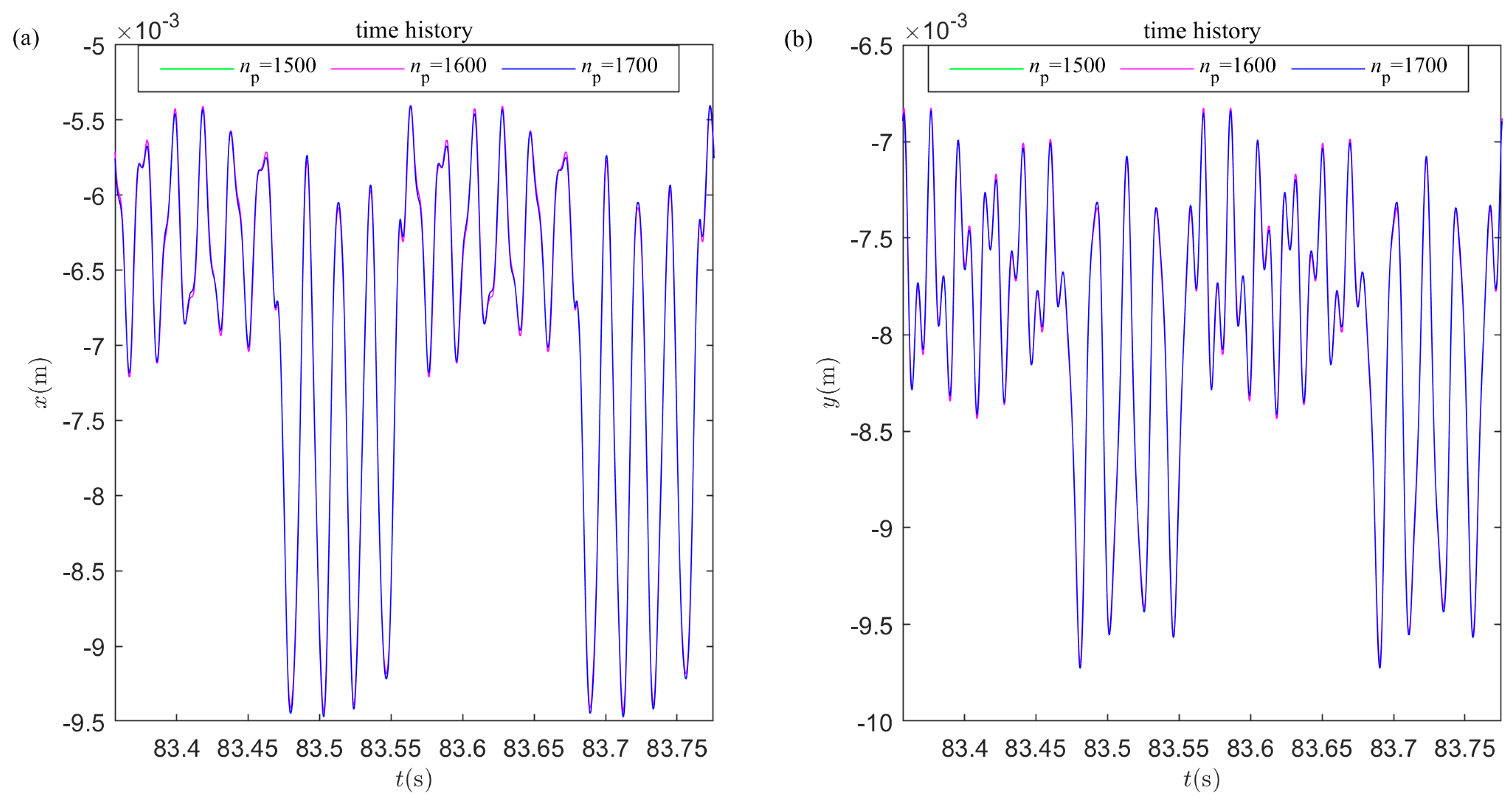
Denote n p as the number of iteration steps of one oscillation period of the belt; the time step d t of the numerical algorithm can be written as  d t = 2 π ω n p . ω = 30   rad / s , k 2 NL = 5000   N / m 3 , N = 160   N are selected in this study. The transient responses of the slider under different numbers of iteration steps are displayed in Figure 2.
As illustrated in Figure 2, the displacement curves for three different iterative steps almost perfectly overlap. No visible deviations or phase shifts are observed. This highly consistent behavior visually demonstrates that the numerical solution has already reached an extremely stable state when the number of iteration steps is 1500. Considering both the stability and computational efficiency of the numerical algorithm, the time step for the numerical simulation is defined as d t = 2 π / ω / 1500 ; in other words, one thousand five hundred data points are sampled for each period of the belt oscillation.

4.2. The Effect of the Oscillatory Angular Frequency ω of the Belt on Vibration Responses

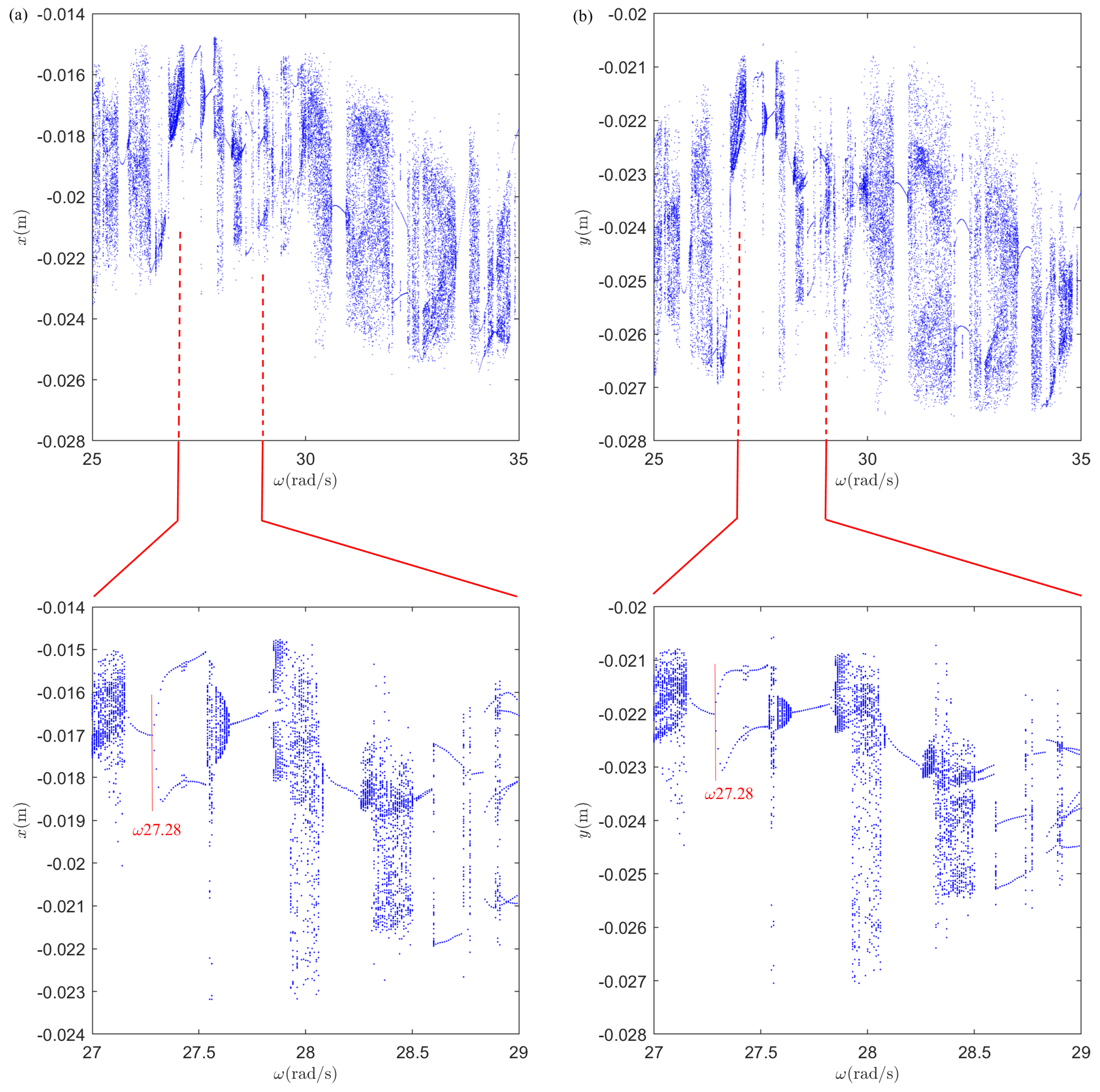
The influence of the oscillatory angular frequency ω of the belt on the vibration response of the slider is studied in this sub-section, and N = 500   N , k 2 NL = 5000   N / m 3 are taken in this study. The bifurcation diagrams and their locally enlarged view of the vibration displacements of the slider in the x and y directions versus the oscillatory angular frequency ω of the belt are displayed in Figure 3. As can be seen from Figure 3, the chaotic motion occurs in certain oscillatory angular frequency bands, which are separated by bands with p -periodic motions ( p = 1 , 2 , 3 , 6 ,   ect . ). From the locally enlarged view of the bifurcation diagrams, it can be seen that within a very narrow range of oscillatory angular frequency variation, the dynamic characteristics of the slider undergo significant changes. This strongly indicates that the dynamic characteristics of the slider are highly sensitive to the variation of oscillatory angular frequency. With the increase of ω , the period-doubling bifurcation occurs when ω > 27.28   rad / s .
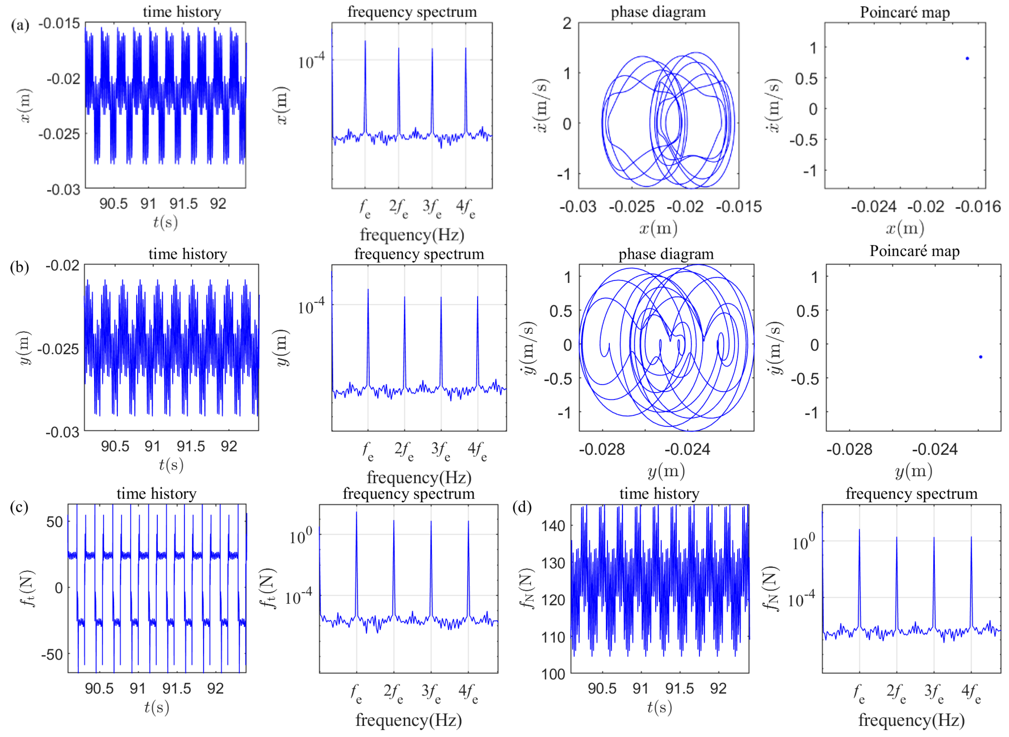
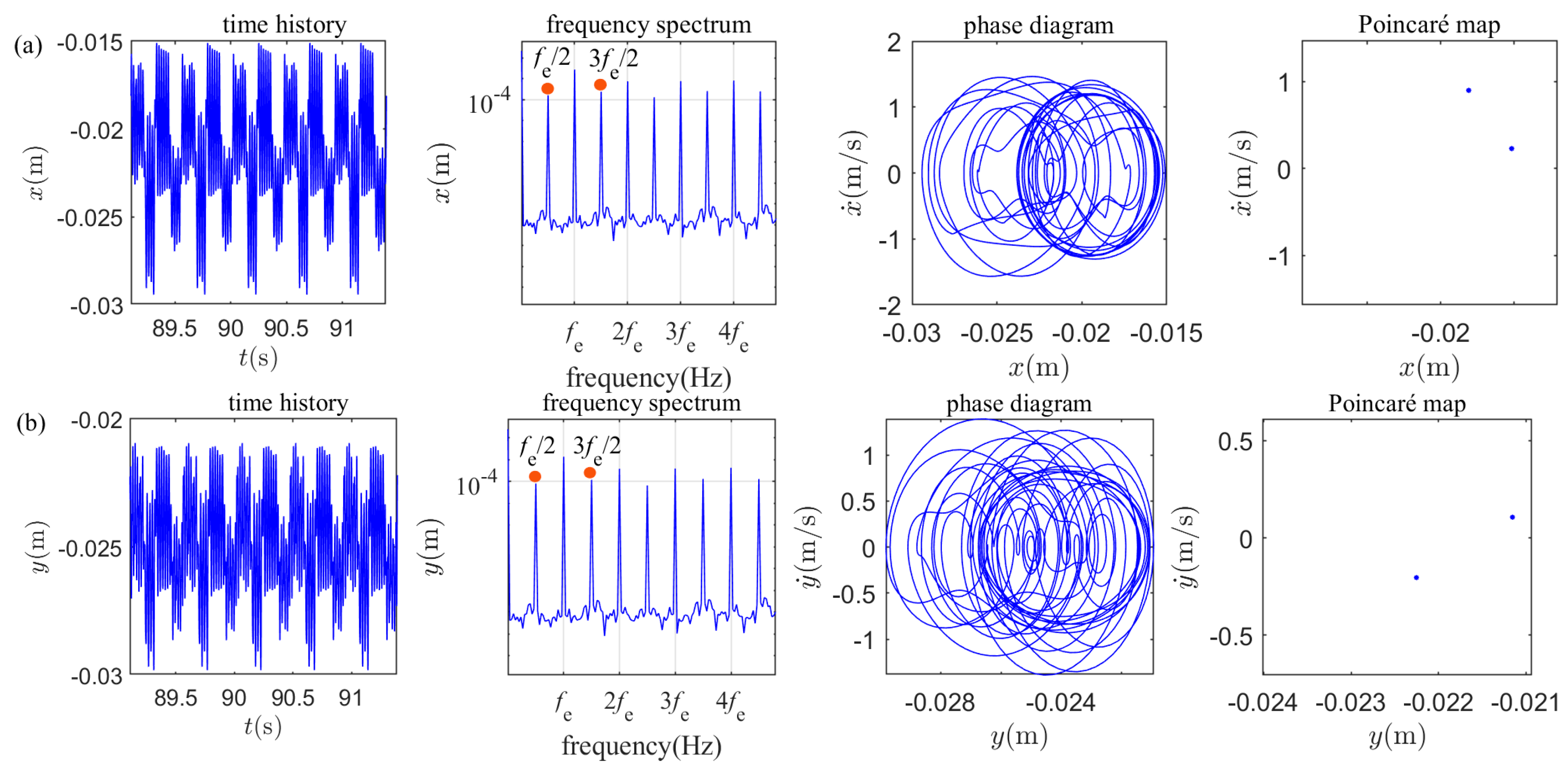
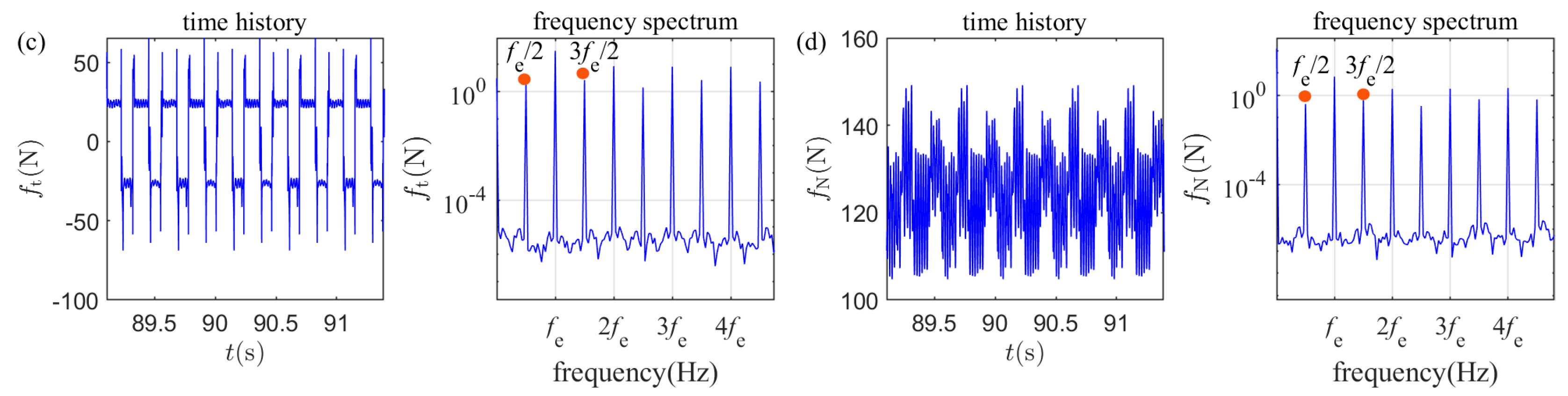
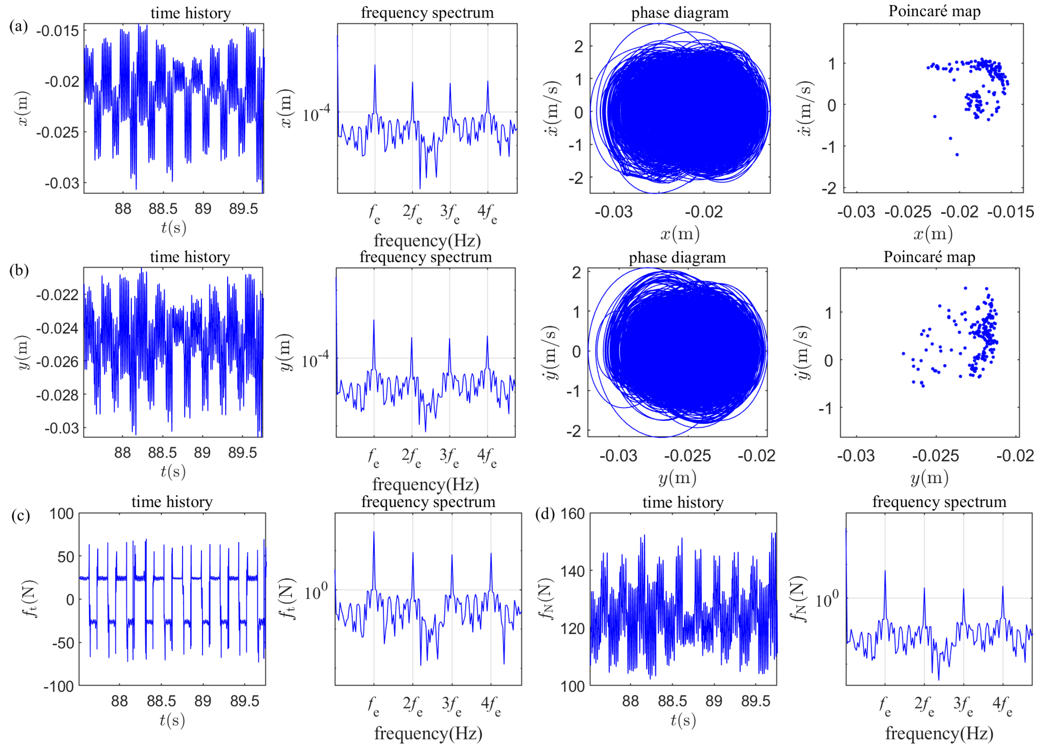
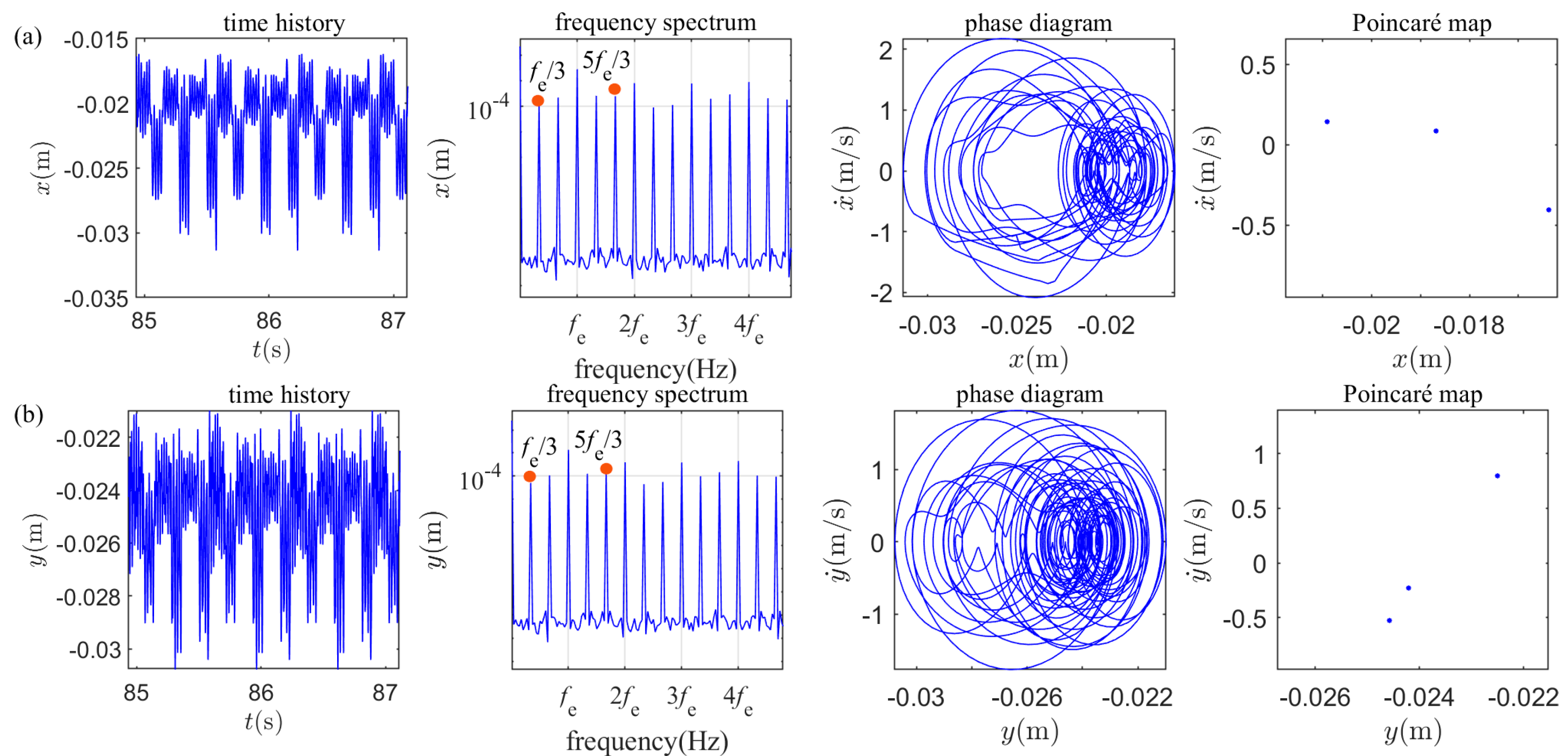
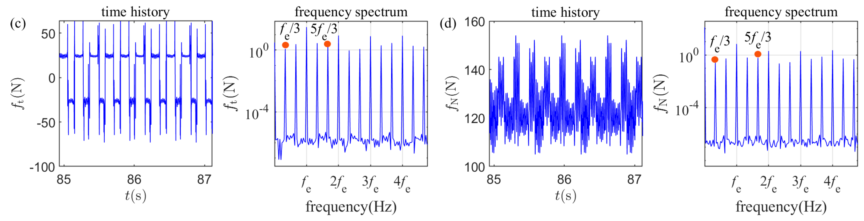
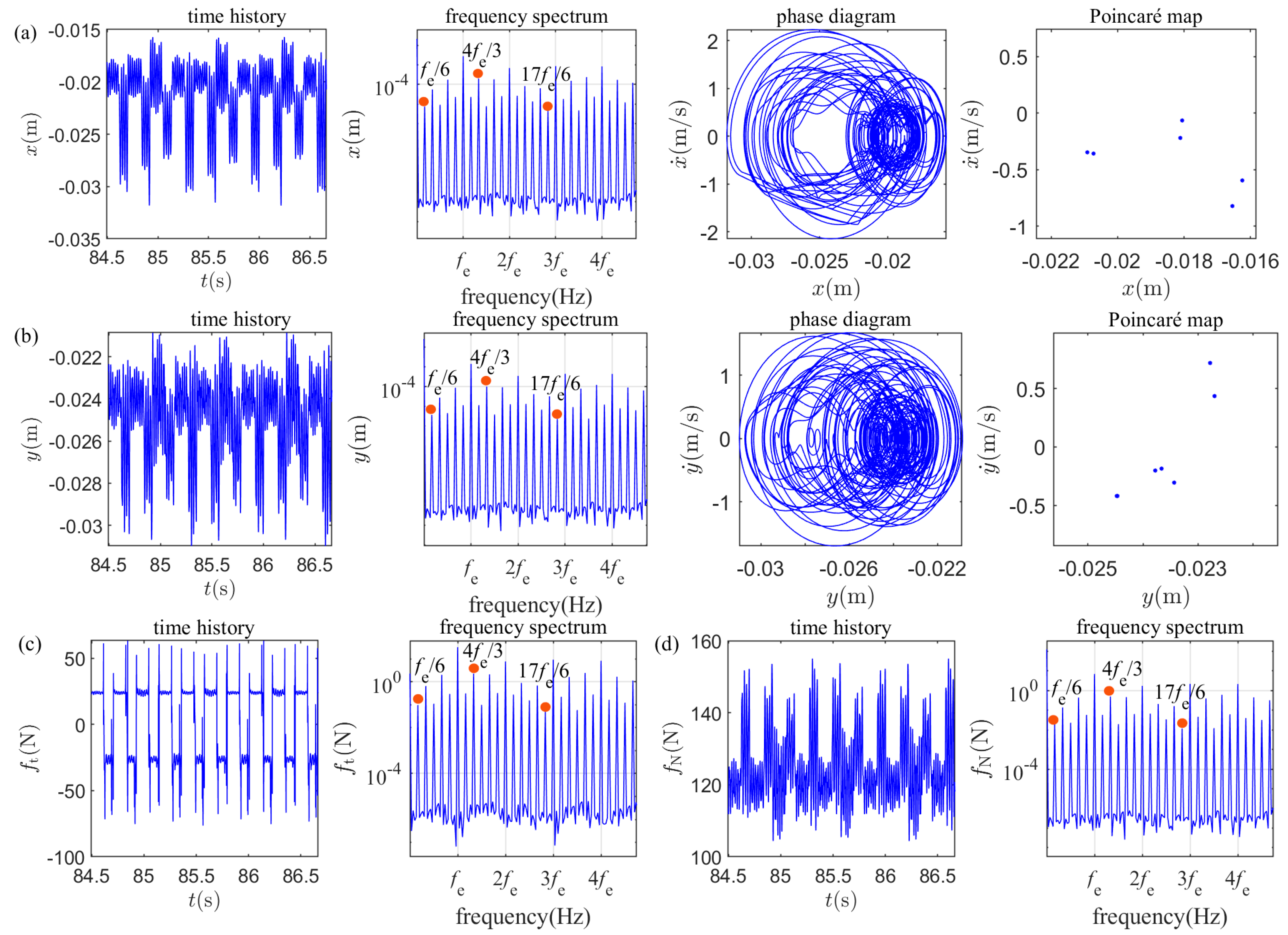
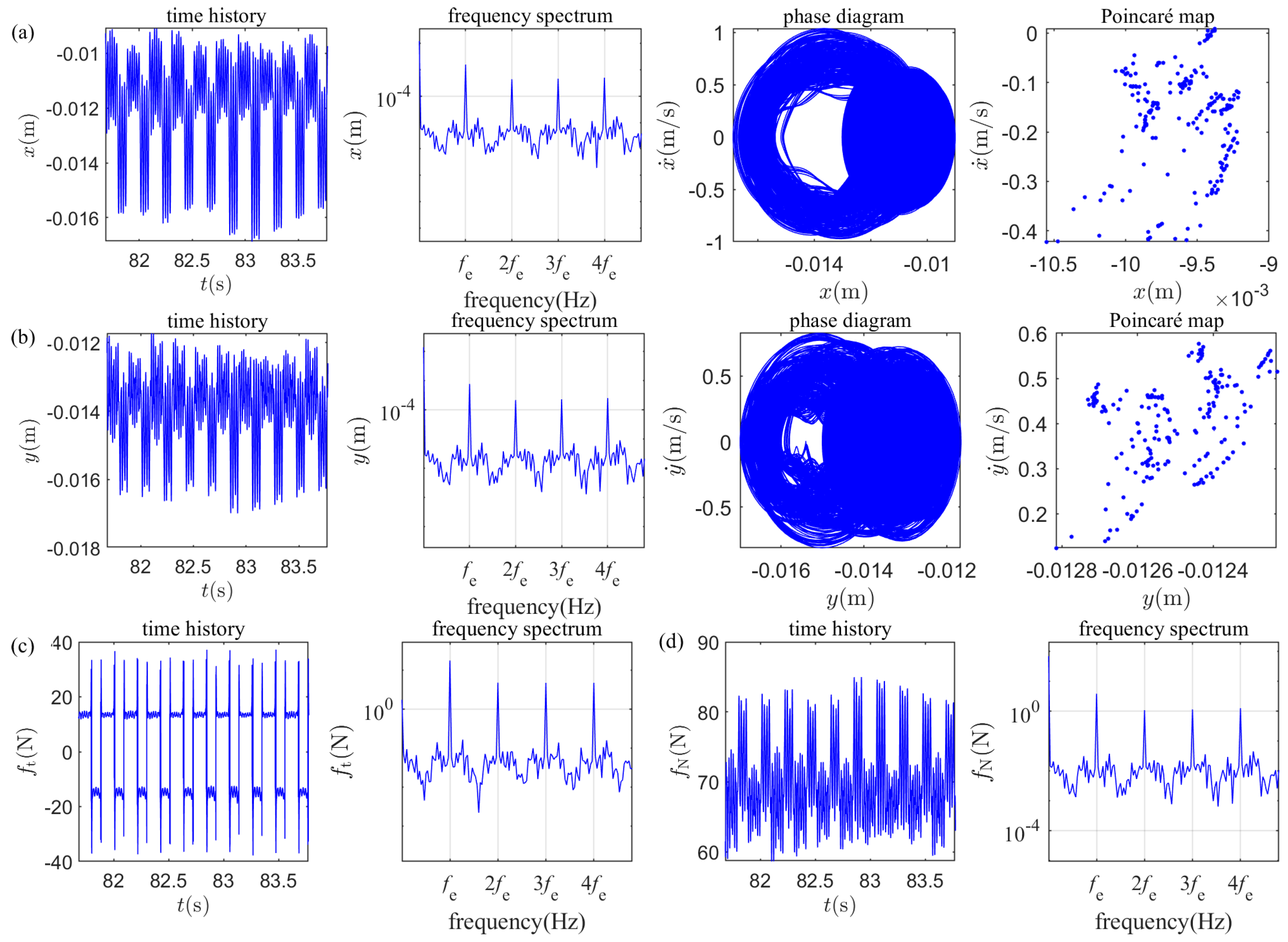
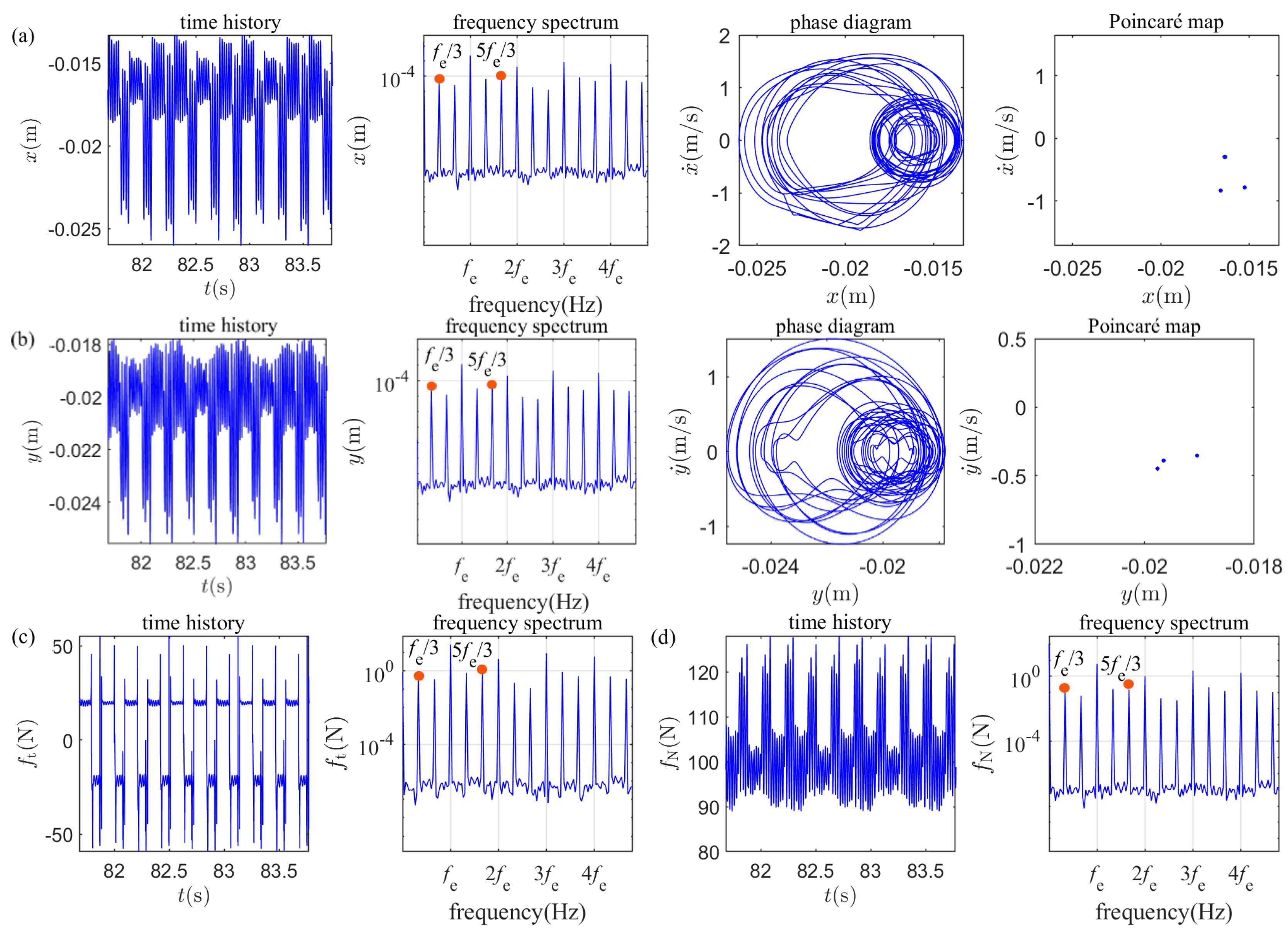
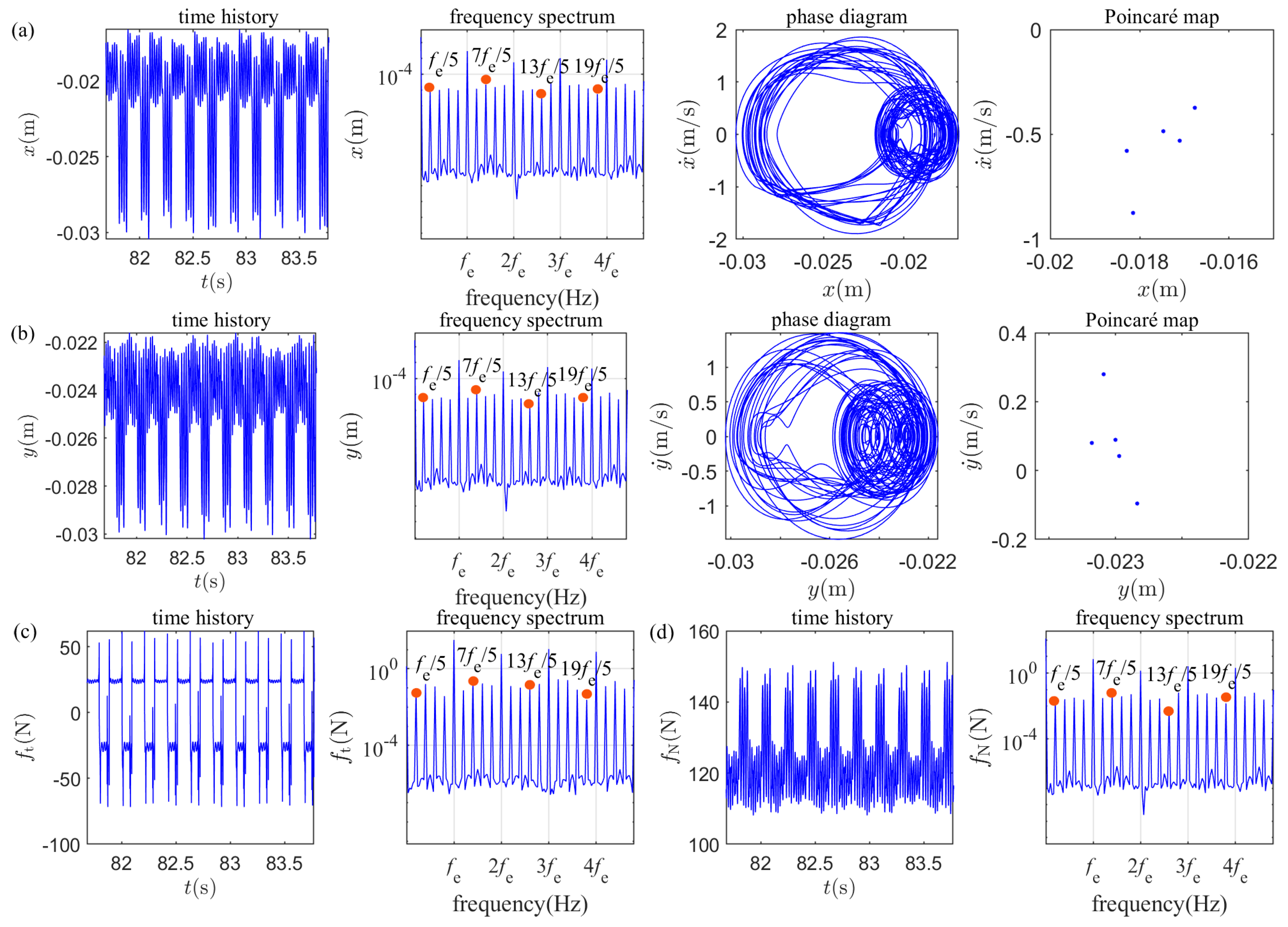
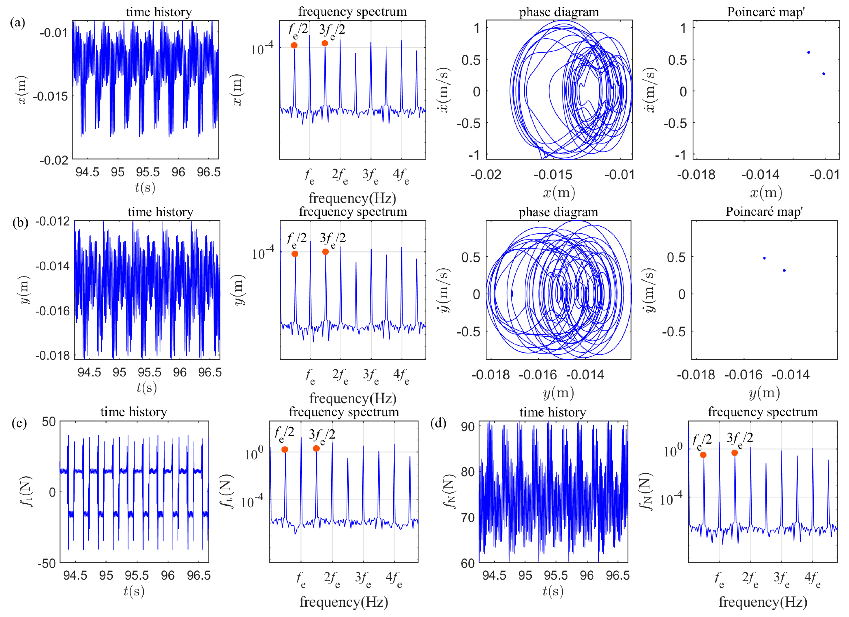
Vibration responses of the slider at ω = 27.2   rad / s ,   27.5   rad / s ,   28   rad / s ,   28.85   rad / s ,     29   rad / s are provided in Figure 4, Figure 5, Figure 6, Figure 7 and Figure 8, respectively. When ω = 27.2   rad / s , the dominated motion of the slider is the period-one ( p 1 ) motion, the time response is regular, there is only one isolated point on the Poincaré map, the fundamental frequency and super-harmonic frequencies ( 2 f e , 3 f e , ect . ) of the oscillatory frequency of the oscillating belt can be observed from the frequency spectrums in Figure 4, and the vibration responses of the slider are still periodic (whose period is equal to the period of the oscillating belt). Higher-order harmonics are primarily caused by the strong non-smooth nonlinearities inherent in the system. Specifically, the discontinuous nature of the alternating stick-slip transitions in the tangential direction, combined with the separation-recontact impacts in the normal direction. The period-two ( p 2 ) motion appears at ω = 27.5   rad / s ; in addition to the fundamental frequency and some super-harmonic frequencies, some fractional frequencies ( f e / 2 , 3 f e / 2 , ect . ) can be found. The reason for p 2 motion is that the periods of the friction force and the normal contact force are both two times of the period of the oscillating belt. Compared with the p 1 motion in which only one isolated point appears on the Poincaré map (see Figure 4), two isolated points appear on the Poincaré map (see Figure 5). Figure 6 displays the chaotic motion of the slider; the correlation dimension of the displacement response data is 2.80 in terms of the Grassberger–Procaccia algorithm [42]. From the phase diagram, it can be seen that the trajectory is not closed; instead, it spreads densely within a certain limited area, forming a complex cluster-like region. From the frequency spectrum, continuous spectrums appear. The time response is irregular, and there are scattered Poincaré points. The period-three ( p 3 ) motion and period-six ( p 6 ) motion that appear at ω = 28.85   rad / s ,   29   rad / s   are illustrated in Figure 7 and Figure 8, respectively; three isolated points and six isolated points appear on the Poincaré map, respectively. In addition to the fundamental frequency and some multiple frequencies, some fractional frequencies can also be observed. The reasons for the appearance of the p 3 motion and p 6 motion are similar to the p 2 motion.

4.3. The Effect of the Vertical Preload N on Vibration Responses

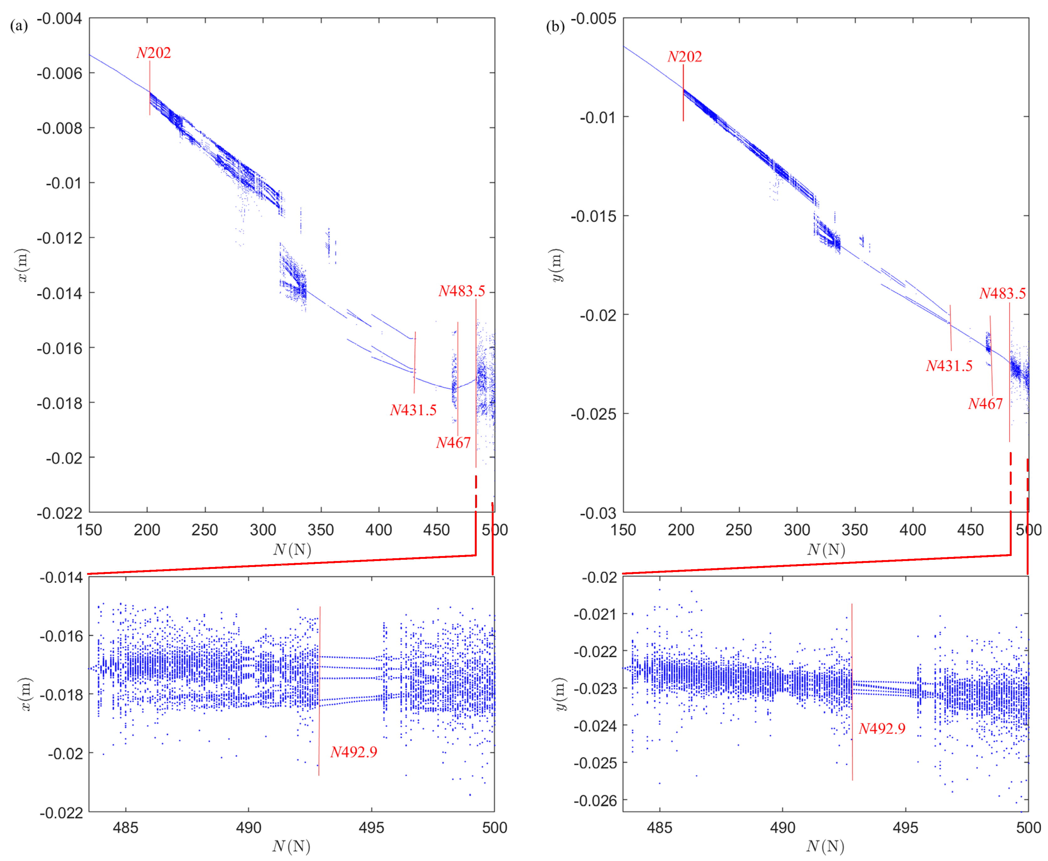
In this sub-section, the influence of the vertical preload N on the vibration response of the slider is explored, and ω = 30   rad / s , k 2 NL = 5000   N / m 3 are selected in this study. The bifurcation diagrams of the vibration displacements of the slider in the x and y directions versus the vertical preload N are shown in Figure 9. With the increase of the vertical preload, the slider alternately gives rise to periodic motion and chaotic motion. It can be seen that within a very brand range (for instance, 150 202 , 467 483.5 , ect . ) of the vertical preload variation, the motion of the slider is always period-one motion. This demonstrates that the influence of the vertical preload on the dynamic characteristics of the slider is not as sensitive as the oscillatory angular frequency. Around N = 202   N , a single point suddenly transforms into a point cloud. A significant displacement jump occurred at N = 431.5   N ; the motion of the slider suddenly changed from period-three to period-one. When N increases to 492.9 N, the point cloud suddenly converges into five discrete lines; the slider then enters the p 5 motion window.
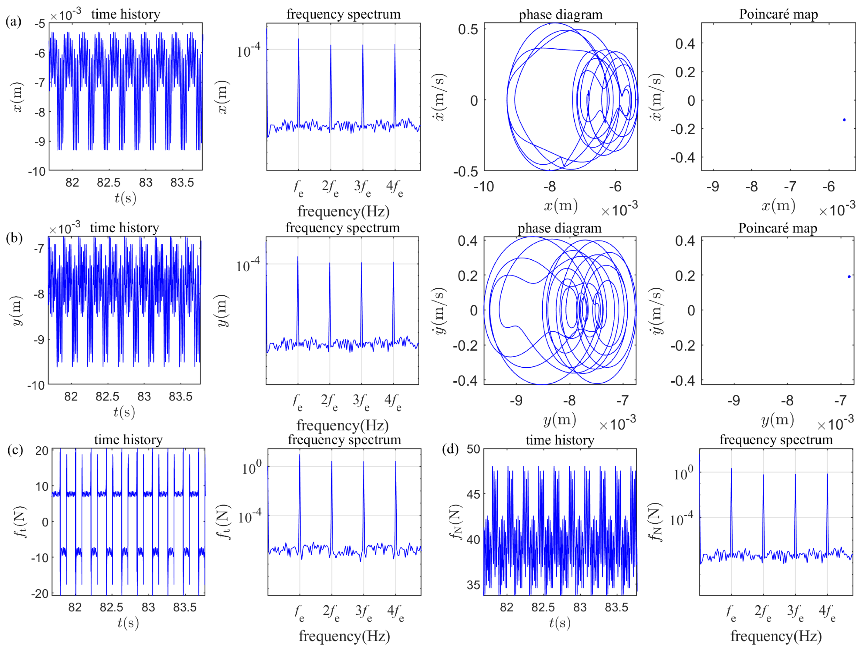
Vibration responses of the slider at four typical vertical preloads ( N = 160   N ,   280   N ,   410   N ,   494   N ) are given in Figure 10, Figure 11, Figure 12 and Figure 13, respectively. Figure 10 shows the period-one ( p 1 ) motion that appears at N = 160   N , whose time-domain waveform exhibits a highly regular, continuously repeating oscillatory pattern. The phase diagram is a closed curve with only one isolated point on the Poincaré map. Due to the presence of some higher-order harmonics ( 2 f e , 3 f e , ect . ), the phase trajectory here is not a simple ellipse but a complex closed shape with multiple intersections and folds. Figure 11 illustrates the chaotic motion of the slider that occurs at N = 280   N ; the correlation dimension of the displacement response data is 2.65 in terms of the Grassberger–Procaccia algorithm [42]. The points on the Poincaré map form a two-dimensional pattern, and the motions between the slider and the belt become more complex with the appearance of the continuous spectrums. The trajectory looks like an extremely dense tangle; although it is generally confined within a roughly circular area, the internal trajectory lines are endlessly intertwined with each other. Figure 7 and Figure 8 display the period-three ( p 3 ) motion and period-five ( p 5 ) motion, which appear at N = 410   N and N = 497   N , respectively. Three isolated points and six isolated points appear on the Poincaré map, respectively; in addition to the fundamental frequency and some multiple frequencies, some fractional frequencies can also be observed. According to the well-known Li-Yorke theorem, p 3  implies chaos. The reason for p 3 motion is that the periods of the friction force and the normal contact force are both three times the period of the oscillating belt.

4.4. The Effect of the Nonlinear Stiffness k 2 NL on Vibration Responses

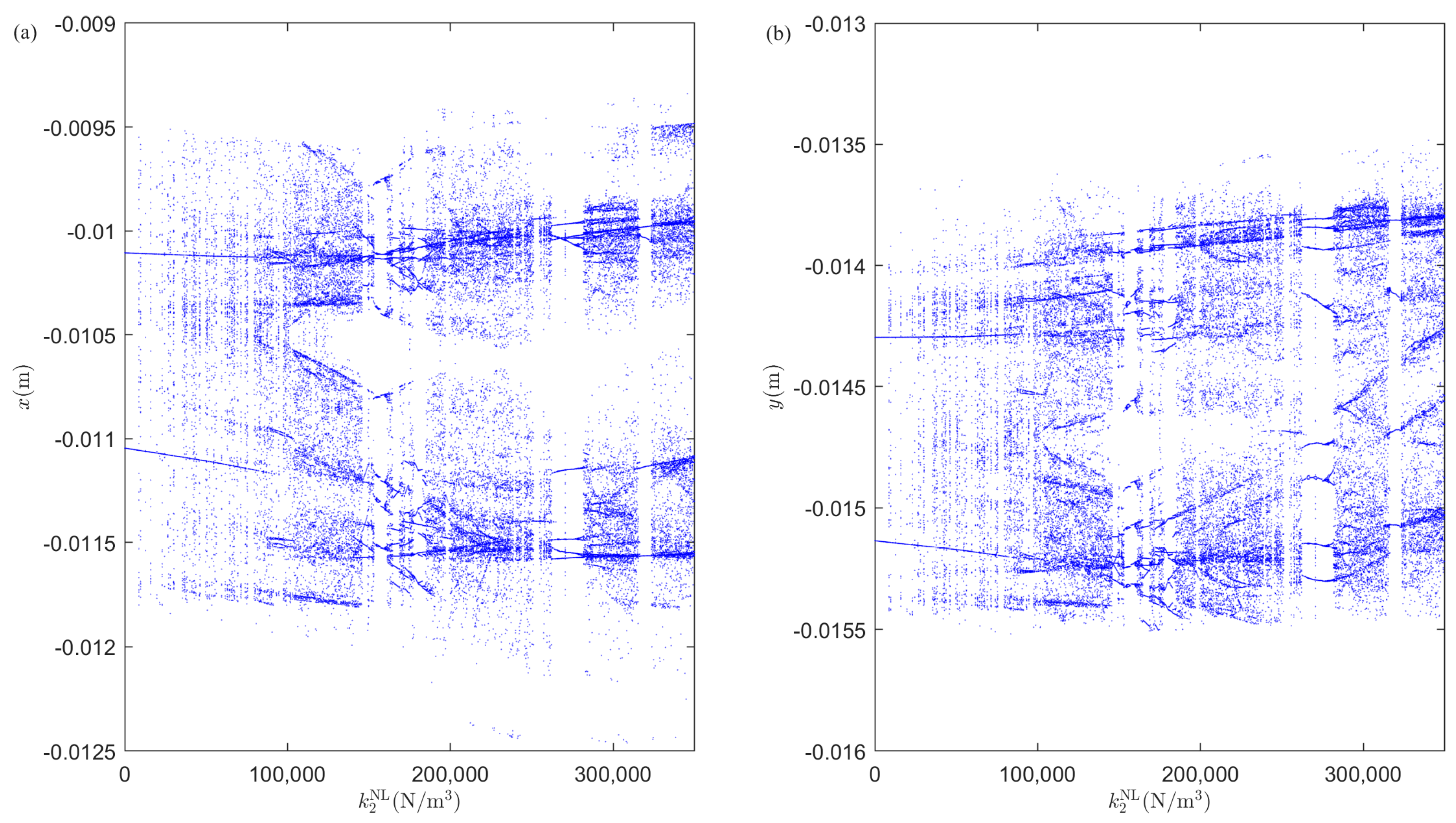
In this sub-section, the influence of the nonlinear stiffness k 2 NL on the vibration response of the slider is examined, and N = 500   N , ω = 26   rad / s are chosen in this study. The bifurcation diagrams of the vibration displacements of the slider in the x and y directions versus the nonlinear stiffness k 2 NL are exhibited in Figure 14. With variation of the nonlinear stiffness, period-two ( p 2 ) motion, period-four ( p 4 ) motion, period-eight ( p 8 ) motion and chaotic motion of the slider can be found. Throughout the entire range of k 2 NL from 0 N/m3 to 350,000 N/m3, the slider does not have a single stable state that can remain unchanged for a long period. The state transitions are extremely frequent. This shows that the nonlinear stiffness has a great influence on the dynamic characteristics of the slider.
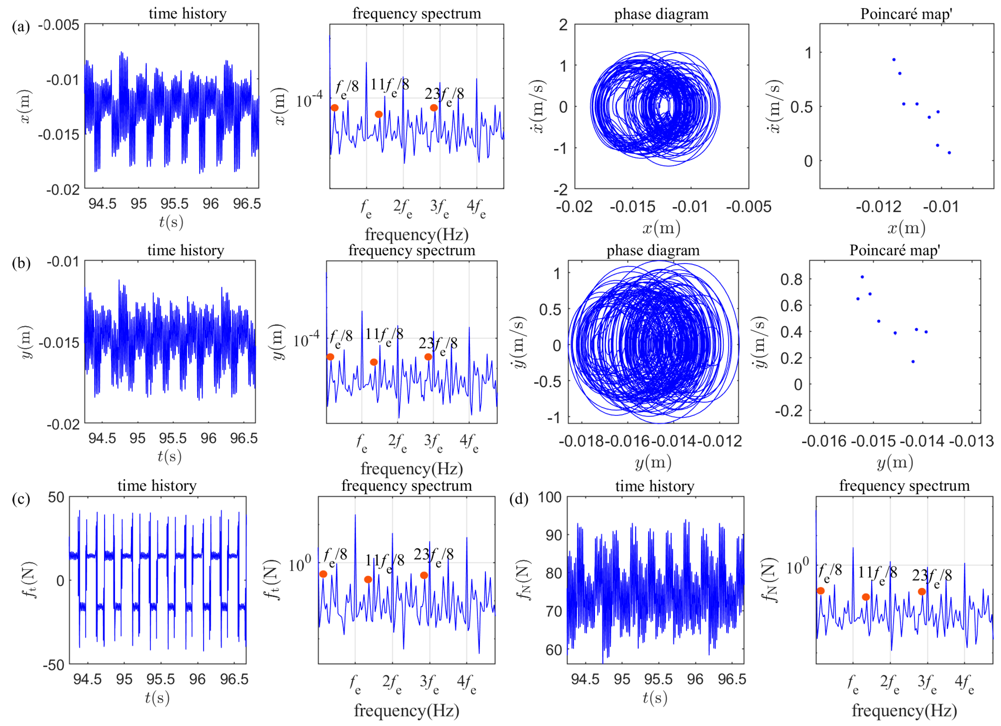
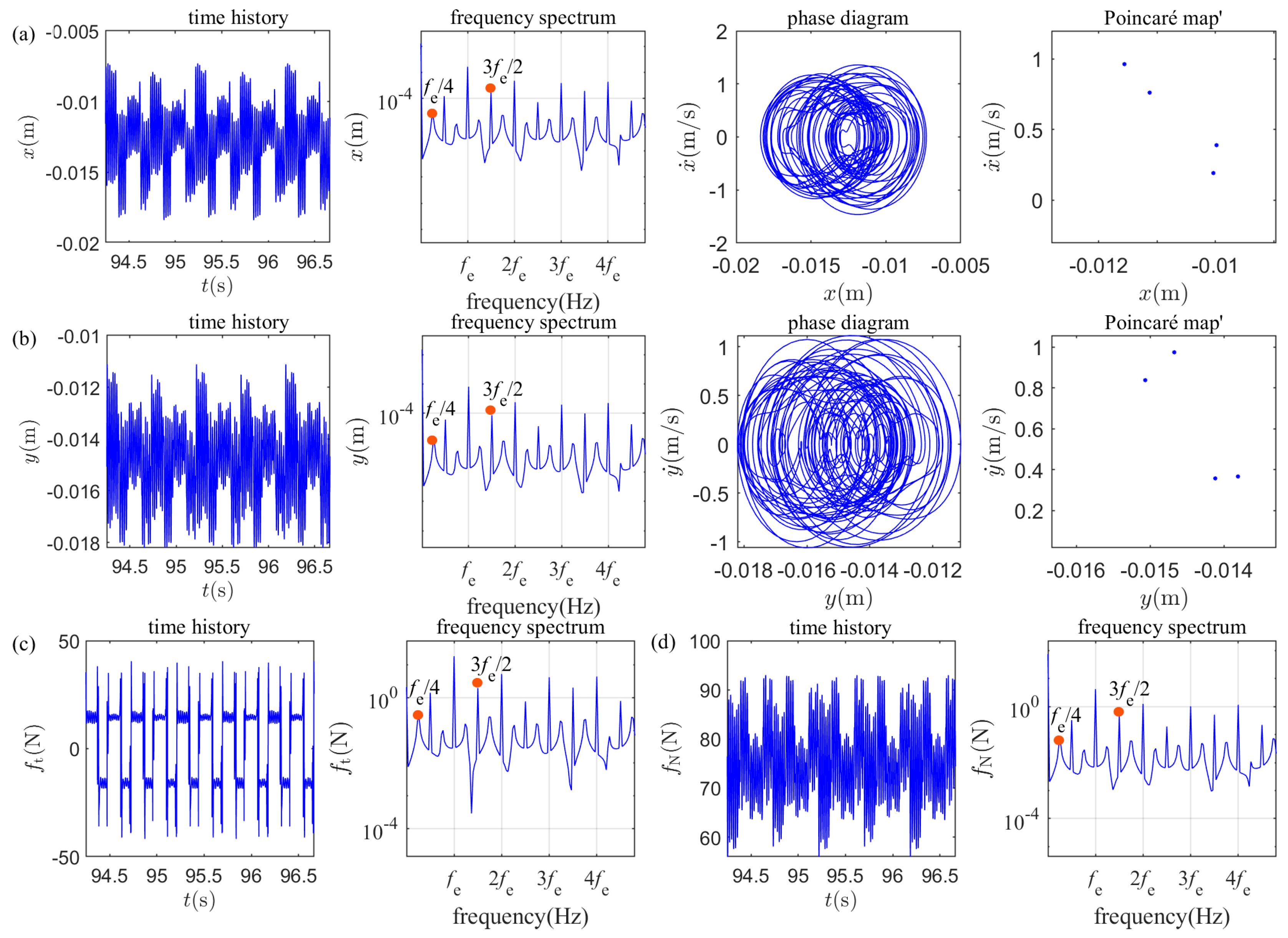
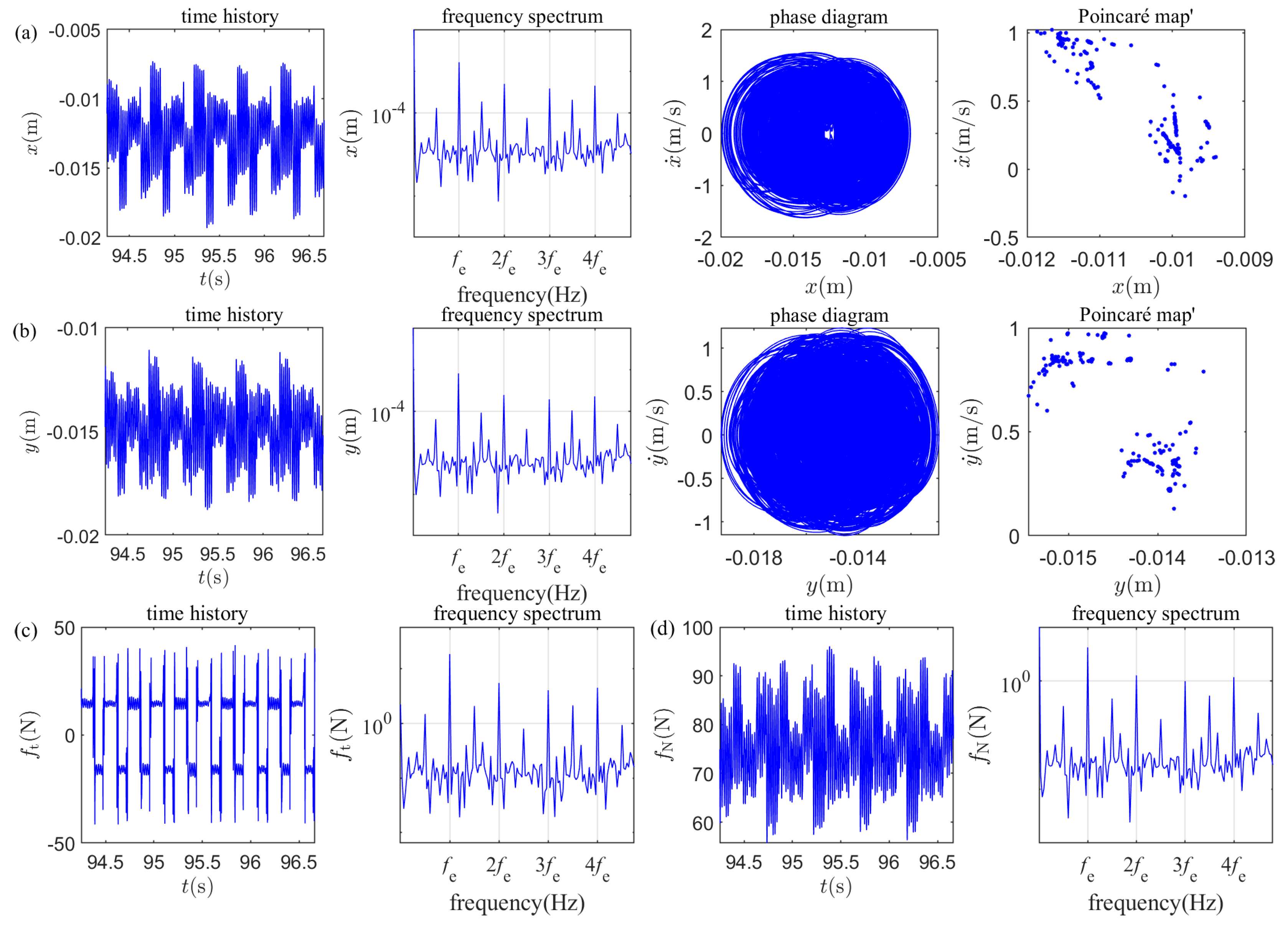
Vibration responses of the slider at different stiffness ratios are provided in Figure 15, Figure 16, Figure 17 and Figure 18. The period-two ( p 2 ) motion that appears at k 2 NL = 0   N / m 3 is exposed at Figure 15 with the appearance of some fractional frequencies ( f e / 2 , 3 f e / 2 , etc.) on the frequency spectrums, whose phase diagram is a closed curve with only two isolated points on the Poincarémap. The period-eight ( p 8 ) motion and period-four ( p 4 ) motion that appear at k 2 NL = 158,000   N / m 3 and k 2 NL = 320,000   N / m 3 are illustrated in Figure 16 and Figure 17, respectively. Eight isolated points and four isolated points appear on the Poincaré map, respectively, in Figure 16 and Figure 17; the fundamental frequency, as well as some multiple and fractional frequencies of the oscillatory frequency of the oscillating belt, all exist. Figure 18 shows the chaotic motion of the slider that occurs at k 2 NL = 340,000   N / m 3 with the appearance of the continuous spectrums; the correlation dimension of the displacement response data is 2.26 in terms of the Grassberger–Procaccia algorithm [42].

5. Conclusions

In this paper, nonlinear vibration characteristics of the slider moving on an oscillating belt are investigated. The main conclusions are as follows:
(1) Within a very narrow range of oscillatory angular frequency variation, the dynamic characteristics of the slider undergo significant changes, indicating that the dynamic characteristics of the slider are highly sensitive to the variation of oscillatory angular frequency. When designing a slider-on-belt system, the oscillation frequency of the belt should be strictly controlled to prevent the system frequency from falling into an extremely narrow sensitive band that could trigger period-doubling bifurcation.
(2) Given that the slider can maintain a stable p 1 motion within a relatively wide range of the preload, engineers can make the slider safely operate within these stable “windows” by actively adjusting or calibrating the vertical preload.
(3) The nonlinear stiffness k 2 NL has a great influence on the dynamic characteristics of the slider. It is necessary to carefully select the contact materials and buffering structures to minimize nonlinear stiffness hardening and avoid structural parameters from entering a dangerous range that compromises long-term stability.
(4) While the current study provides theoretical insights into the non-smooth dynamics of the slider, the lack of experimental validation for the current work remains a limitation. Future work will focus on an experimental study.

Author Contributions

Conceptualization, B.H. and Y.Y.; methodology, B.H., S.H. and C.F.; software, B.H., S.P. and Z.Z.; formal analysis, B.H., S.P. and Z.Z.; data curation, Y.Y. and C.F.; writing—original draft, B.H.; writing—review and editing, B.H. and S.H.; supervision, S.H.; and funding acquisition, B.H. and Y.Y. All authors have read and agreed to the published version of the manuscript.

Funding

This research was funded by the National Natural Science Foundation of China, grant number 12102239, and the Natural Science Basic Research Program of Shaanxi, grant number 2025JC-JCQN-067.

Data Availability Statement

The original contributions presented in this study are included in the article. Further inquiries can be directed to the corresponding author.

Conflicts of Interest

The authors declare no conflicts of interest.

Abbreviations

The following abbreviations are used in this manuscript:
2D-NLFISTwo-dimensional nonlinear friction-induced slider

References

  1. Berger, E. Friction modeling for dynamic system simulation. Appl. Mech. Rev. 2002, 55, 535–577. [Google Scholar] [CrossRef]
  2. Ouyang, H.; Nack, W.; Yuan, Y.; Chen, F. Numerical analysis of automotive disc brake squeal: A review. Int. J. Veh. Noise Vib. 2005, 1, 207–231. [Google Scholar] [CrossRef]
  3. Ghazaly, N.M.; El-Sharkawy, M.; Ahmed, I. A review of automotive brake squeal mechanisms. J. Mech. Des. Vib. 2014, 1, 5–9. [Google Scholar]
  4. Popp, K.; Stelter, P. Stick-slip vibrations and chaos. Philos. Trans. R. Soc. Lond. Ser. A 1990, 332, 89–105. [Google Scholar] [CrossRef]
  5. Hoffmann, N.G.L. Effects of damping on mode-coupling instability in friction induced oscillations. Z. Angew. Math. Mech. 2003, 83, 524–534. [Google Scholar]
  6. Wagner, U.V.; Hochlenert, D.; Hagedorn, P. Minimal models for disk brake squeal. J. Sound. Vib. 2007, 302, 527–539, Erratum in J. Sound Vib. 2023, 559, 117776. [Google Scholar] [CrossRef]
  7. Elmaian, A.; Gautier, F.; Pezerat, C.; Duffal, J.M. How can automotive friction-induced noises be related to physical mechanisms? Appl. Acoust. 2014, 76, 391–401. [Google Scholar] [CrossRef]
  8. Li, Z.; Ouyang, H.; Guan, Z. Nonlinear friction-induced vibration of a slider–belt system. J. Vib. Acoust. 2016, 138, 041006. [Google Scholar]
  9. Wang, X.; Long, X.; Yue, X.; Dai, H.; Atluri, S.N. Bifurcation analysis of stick-slip vibration in a 2-DOF nonlinear dynamical system with dry friction. Commun. Nonlinear Sci. Numer. Simul. 2022, 111, 106475. [Google Scholar]
  10. Zhang, Z.; Oberst, S.; Lai, J.C.S. On the potential of uncertainty analysis for prediction of brake squeal propensity. J. Sound. Vib. 2016, 377, 123–132. [Google Scholar] [CrossRef]
  11. Hu, H.; Batou, A.; Ouyang, H. Friction-induced vibration of a stick–slip oscillator with random field friction modelling. Mech. Syst. Signal Process. 2023, 183, 109572. [Google Scholar]
  12. Wang, Z.; Mo, J.; Zhao, C.; Wang, Q.; Wang, K. Dynamic modeling and brake stick-slip vibration analysis of a vehicle-track system with disc-pad nonlinear frictions. Tribol. Int. 2025, 202, 110317. [Google Scholar]
  13. Capozza, R.; Rubinstein, S.M.; Barel, I.; Urbakh, M.; Fineberg, J. Stabilizing stick-slip friction. Phys. Rev. Lett. 2011, 107, 024301. [Google Scholar] [CrossRef] [PubMed]
  14. He, B.; Ren, X.; Ouyang, H.; Mei, Y.; Yang, Y.; He, S. Dynamic modeling and characteristics of integrally shrouded group blades with two-dimensional rub-impact considering the stick-slip motion. Appl. Math. Model. 2025, 148, 116229. [Google Scholar]
  15. Chatelet, E.; Michon, G.; Manin, L.; Jacquet-Richardet, G. Stick/slip phenomena in dynamics: Choice of contact model. Numer. Predict. Exp. Mech. Mach. Theory 2008, 43, 1211–1224. [Google Scholar] [CrossRef]
  16. Pascal, M. Sticking and nonsticking orbits for a two-degree-of-freedom oscillator excited by dry friction and harmonic loading. Nonlinear Dyn. 2014, 77, 267–276. [Google Scholar]
  17. Gweon, J.H.; Joo, B.S.; Jang, H. The effect of short glass fiber dispersion on the friction and vibration of brake friction materials. Wear 2016, 362, 61–67. [Google Scholar] [CrossRef]
  18. Lima, R.; Sampaio, R. Parametric analysis of the statistical model of the stick-slip process. J. Sound. Vib. 2017, 397, 141–151. [Google Scholar] [CrossRef]
  19. Wang, X.; Huang, B.; Wang, R.; Mo, J.; Ouyang, H. Friction-induced stick-slip vibration and its experimental validation. Mech. Syst. Signal Process. 2020, 142, 106705. [Google Scholar]
  20. Kang, J.; Krousgrill, C.M.; Sadeghi, F. Oscillation pattern of stick–slip vibrations. Int. J. Non Linear Mech. 2009, 44, 820–828. [Google Scholar] [CrossRef]
  21. Lima, R.; Sampaio, R. Construction of a statistical model for the dynamics of a base-driven stick-slip oscillator. Mech. Syst. Signal Process. 2017, 91, 157–166. [Google Scholar]
  22. Du, Z.; Fang, H.; Zhan, X.; Xu, J. Experiments on vibration-driven stick-slip locomotion: A sliding bifurcation perspective. Mech. Syst. Signal Process. 2018, 105, 261–275. [Google Scholar]
  23. Leine, R.I.; Van Campen, D.H.; de Kraker, A.; van den Steen, L. Stick-slip vibrations induced by alternate friction models. Nonlinear Dyn. 1998, 16, 41–54. [Google Scholar] [CrossRef]
  24. Feeny, B.; Guran, A.; Hinrichs, N.; Popp, K. A historical review on dry friction and stick-slip phenomena. Appl. Mech. Rev. 1998, 51, 321–341. [Google Scholar] [CrossRef]
  25. Luo, A.C.J.; Gegg, B.C. Stick and non-stick periodic motions in periodically forced oscillators with dry friction. J. Sound. Vib. 2006, 291, 132–168. [Google Scholar]
  26. Yoon, S.W.; Shin, M.W.; Lee, W.G.; Jang, H. Effect of surface contact conditions on the stick–slip behavior of brake friction material. Wear 2012, 294–295, 305–312. [Google Scholar] [CrossRef]
  27. Balaram, B.; Santhosh, B.; Awrejcewicz, J. Frequency entrainment and suppression of stick–slip vibrations in a 3 DoF discontinuous disc brake model. J. Sound. Vib. 2022, 538, 117224. [Google Scholar]
  28. Won, H.I.; Chung, J. Stick–slip vibration of an oscillator with damping. Nonlinear Dyn. 2016, 86, 257–267. [Google Scholar] [CrossRef]
  29. Chen, G.X.; Zhou, Z.R. Time–frequency analysis of friction-induced vibration under reciprocating sliding conditions. Wear 2007, 262, 1–10. [Google Scholar]
  30. Brunetti, J.; Massi, F.; D’Ambrogio, W.; Berthier, Y. A new instability index for unstable mode selection in squeal prediction by complex eigenvalue analysis. J. Sound. Vib. 2016, 377, 106–122. [Google Scholar] [CrossRef]
  31. Zhu, Y.G.; Wang, R.L.; Xiang, Z.Y.; Mo, J.L.; Ouyang, H. The effect of dynamic normal force on the stick–slip vibration characteristics. Nonlinear Dyn. 2022, 110, 69–93. [Google Scholar] [CrossRef]
  32. Wang, Q.; Zhang, Q.X.; Wang, Z.W.; Mo, J.L.; Jin, W.W.; Zhu, S. Identification of Stribeck model parameters to accurately reveal stick–slip characteristics of a disc–block friction system. Tribol. Trans. 2023, 66, 1026–1042. [Google Scholar]
  33. Choi, J.; Seo, H.; Sohn, S.S.; Jang, H. Size effects of brake pads on stick–slip phenomena. Tribol. Int. 2023, 189, 108944. [Google Scholar]
  34. Bouazizi, M.; Soula, M.; Lazghab, T. Numerical analysis of brake squeal noise—Application to the disk brake systems. Noise Vib. Worldw. 2024, 55, 117–122. [Google Scholar]
  35. Zhou, H.; Wang, Z.; Wang, Q.; Mo, J.; Zhao, C.; Wang, K. Dynamic models and analysis of key factors influencing stick–slip vibration in disc brake system. Railw. Eng. Sci. 2025, 34, 242–256. [Google Scholar] [CrossRef]
  36. He, B.; Pan, S.; Zhang, Z.; Mei, Y.; Zhang, W. Numerical Simulation of the Dry Friction Constrained System Based on Coulomb Stick-Slip Motion. Symmetry 2026, 18, 20738994. [Google Scholar]
  37. Sui, X.; Ding, Q. Numerical Analysis of Dry Friction-Induced Vibration of Moving Slider-Elastic Annular Beam System. Trans. Nanjing Univ. Aeronaut. Astronaut. 2018, 35, 84–93. [Google Scholar]
  38. Liu, N.; Ouyang, H. Friction-induced vibration of a slider on an elastic disc spinning at variable speeds. Nonlinear Dyn. 2019, 98, 39–60. [Google Scholar] [CrossRef]
  39. Luo, A.C.J.; Gegg, B.C. Periodic motions in a periodically forced oscillator moving on an oscillating belt with dry friction. J. Comput. Nonlinear Dyn. 2006, 1, 212–220. [Google Scholar] [CrossRef]
  40. Hoffmann, N.; Fischer, M.; Allgaier, R.; Gaul, L. A minimal model for studying properties of the mode-coupling type instability in friction induced oscillations. Mech. Res. Commun. 2002, 29, 197–205. [Google Scholar] [CrossRef]
  41. Li, Z.; Ouyang, H.; Guan, Z. Friction-induced vibration of an elastic disc and a moving slider with separation and reattachment. Nonlinear Dyn. 2016, 87, 1045–1067. [Google Scholar] [CrossRef]
  42. Grassberger, P.; Procaccia, I. Measuring the strangeness of strange attractors. Phys. D Nonlinear Phenom. 1983, 9, 189–208. [Google Scholar] [CrossRef]
Figure 1. A 2D-NLFIS model moving on an oscillating belt.
Symmetry 18 01126 g001
Figure 2. The transient responses of the slider under different numbers of iteration steps: (a) x direction; (b) y direction.
Symmetry 18 01126 g002
Figure 3. Bifurcation diagrams and their locally enlarged view of the vibration displacements of the slider versus the oscillatory angular frequency ω of the belt: (a) x direction; (b) y direction.
Symmetry 18 01126 g003
Figure 4. Vibration responses of the slider ( ω = 27.2   rad / s ): (a) displacement in the x direction, (b) displacement in the y direction, (c) friction force, and (d) normal contact force.
Symmetry 18 01126 g004
Figure 5. Vibration responses of the slider ( ω = 27.5   rad / s ): (a) displacement in the x direction, (b) displacement in the y direction, (c) friction force, and (d) normal contact force.
Symmetry 18 01126 g005aSymmetry 18 01126 g005b
Figure 6. Vibration responses of the slider ( ω = 28   rad / s ): (a) displacement in the x direction, (b) displacement in the y direction, (c) friction force, and (d) normal contact force.
Symmetry 18 01126 g006
Figure 7. Vibration responses of the slider ( ω = 28.85   rad / s ): (a) displacement in the x direction, (b) displacement in the y direction, (c) friction force, and (d) normal contact force.
Symmetry 18 01126 g007aSymmetry 18 01126 g007b
Figure 8. Vibration responses of the slider ( ω = 29   rad / s ): (a) displacement in the x direction, (b) displacement in the y direction, (c) friction force, and (d) normal contact force.
Symmetry 18 01126 g008
Figure 9. Bifurcation diagrams and its locally enlarged view of the vibration displacements of the slider versus the vertical preload N : (a) x direction; (b) y direction.
Symmetry 18 01126 g009
Figure 10. Vibration responses of the slider ( N = 160   N ): (a) displacement in the x direction, (b) displacement in the y direction, (c) friction force, and (d) normal contact force.
Symmetry 18 01126 g010
Figure 11. Vibration responses of the slider ( N = 280   N ): (a) displacement in the x direction, (b) displacement in the y direction, (c) friction force, and (d) normal contact force.
Symmetry 18 01126 g011
Figure 12. Vibration responses of the slider ( N = 410   N ): (a) displacement in the x direction, (b) displacement in the y direction, (c) friction force, and (d) normal contact force.
Symmetry 18 01126 g012
Figure 13. Vibration responses of the slider ( N = 494   N ): (a) displacement in the x direction, (b) displacement in the y direction, (c) friction force, and (d) normal contact force.
Symmetry 18 01126 g013
Figure 14. Bifurcation diagrams of the vibration displacements of the slider versus the nonlinear stiffness η : (a) x direction; (b) y direction.
Symmetry 18 01126 g014
Figure 15. Vibration responses of the slider ( k 2 NL = 0   N / m 3 ): (a) displacement in the x direction, (b) displacement in the y direction, (c) friction force, and (d) normal contact force.
Symmetry 18 01126 g015
Figure 16. Vibration responses of the slider ( k 2 NL = 158,000   N / m 3 ): (a) displacement in the x direction, (b) displacement in the y direction, (c) friction force, and (d) normal contact force.
Symmetry 18 01126 g016
Figure 17. Vibration responses of the slider ( k 2 NL = 320,000   N / m 3 ): (a) displacement in the x direction, (b) displacement in the y direction, (c) friction force, and (d) normal contact force.
Symmetry 18 01126 g017
Figure 18. Vibration responses of the slider ( k 2 NL = 340,000   N / m 3 ): (a) displacement in the x direction, (b) displacement in the y direction, (c) friction force, and (d) normal contact force.
Symmetry 18 01126 g018
Table 1. Values of the main system parameters [28,41].
ArgumentValueArgumentValue
m 0.1 kg c 1 0.5   N s / m
c 2 0.5   N s / m c 3 0.5   N s / m
k 1 1 × 10 4   N / m k 2 0.5 × 10 4   N / m
k 3 4 × 10 4   N / m v 0 1   m / s
v v 4   m / s φ 0
α 2 π / 3 μ s 0.5
μ k 0.2 λ 3 s/m
Disclaimer/Publisher’s Note: The statements, opinions and data contained in all publications are solely those of the individual author(s) and contributor(s) and not of MDPI and/or the editor(s). MDPI and/or the editor(s) disclaim responsibility for any injury to people or property resulting from any ideas, methods, instructions or products referred to in the content.