1. Introduction
Global warming is one of the most critical and immediate challenges facing humanity. At the Conference of the Parties (COP-21) held in Paris, 196 countries signed the Paris Agreement, committing to limit global temperature increases between 1.5 °C and 2 °C above pre-industrial levels. Current studies estimate that global temperatures will exceed 2 °C [
1,
2]. This poses a significant risk to both natural ecosystems, including more frequent extreme weather events, increasing sea levels, and negative implications for food and water security. A recent study examined [
3] the influence of global warming on the frequency of La-Nina events. Their findings suggested that unless greenhouse gas emissions are reduced, the frequency of La Niña events is likely to increase over time. Similar studies performed by [
4,
5,
6,
7,
8,
9,
10,
11,
12] have demonstrated the harmful effects of global warming on both ecosystems and human populations. Hence, there is an urgent need to reduce greenhouse gas emissions.
The world’s population is expected to grow significantly during the next several decades. According to a United Nations report, the world’s population is expected to rise by 2.1 billion from 2024 to 9.7 billion by 2050 and 10.3 billion by 2084 [
13]. The majority of this increase is likely to occur in low-income countries, while wealthy countries are anticipated to see a decline in population growth. Additionally, industrialisation and economic expansion in many regions are expected to increase the energy demand. Current estimates indicate that global energy consumption is expected to increase by approximately 40% by 2050 compared to 2022. This escalation is a result of heightened demand originating from Asia and Africa [
14].
Renewable energy systems can play a crucial role in meeting the growing energy demands. Studies indicate that renewable energy sources contribute to mitigating temperature and carbon emissions [
15]. Additionally, the integration of renewable energy contributes to energy security, reducing dependency on fossil fuels. Renewable energies, such as solar and hydropower, are influencing global energy demand due to advancements in adaptability, cost reductions, and improved efficiency. Solar and wind have demonstrated technical advancements, competing with mainstream non-renewable energy sources. Additionally, wind, solar and hydropower are playing a substantial role in reducing carbon discharge [
16].
Solar energy is readily available to harness and accounts for nearly 31% of the world’s renewable energy capacity, making it the second most installed renewable energy technology after hydropower. Due to the increasing number of solar installations around the world, it is estimated that solar energy will become the second most significant source of electricity generation after wind energy, accounting for 25% of the total electricity requirement by 2050 [
17]. The dominance of solar energy is attributed to its noiseless, non-hazardous energy generation. However, incorporating solar energy presents its challenges. Installing Photovoltaic (PV) panels requires increased land use, which is not abundantly available [
18]. Furthermore, ground-mounted solar installations must compete with increasing urbanisation and industrialisation. In the EU alone, the need for ground-mounted PV will incorporate 1–1.4% of the land in comparison to the urban land available [
19]. To ensure optimal efficiency and performance of Photovoltaic (PV) cells, temperature constraints, environmental circumstances, and geographical limitations must be considered [
20], further limiting potential installation locations.
To address these imminent issues, floating photovoltaics (FPVs) have emerged as a viable alternative to ground-mounted photovoltaics. FPVs involve the deployment of solar panels, supported by floating structures, on water bodies such as lakes, reservoirs, and near- and offshore locations. This innovative approach solves the issue of land scarcity and leverages the cooling properties of the aquatic environment [
21]. An FPV could demonstrate an increased efficiency of 10% while decreasing temperature by 25%, due to cooling when installed in water [
22]. Cooling due to the water surface can contribute to increased energy generation in comparison to land-mounted PVs [
21].
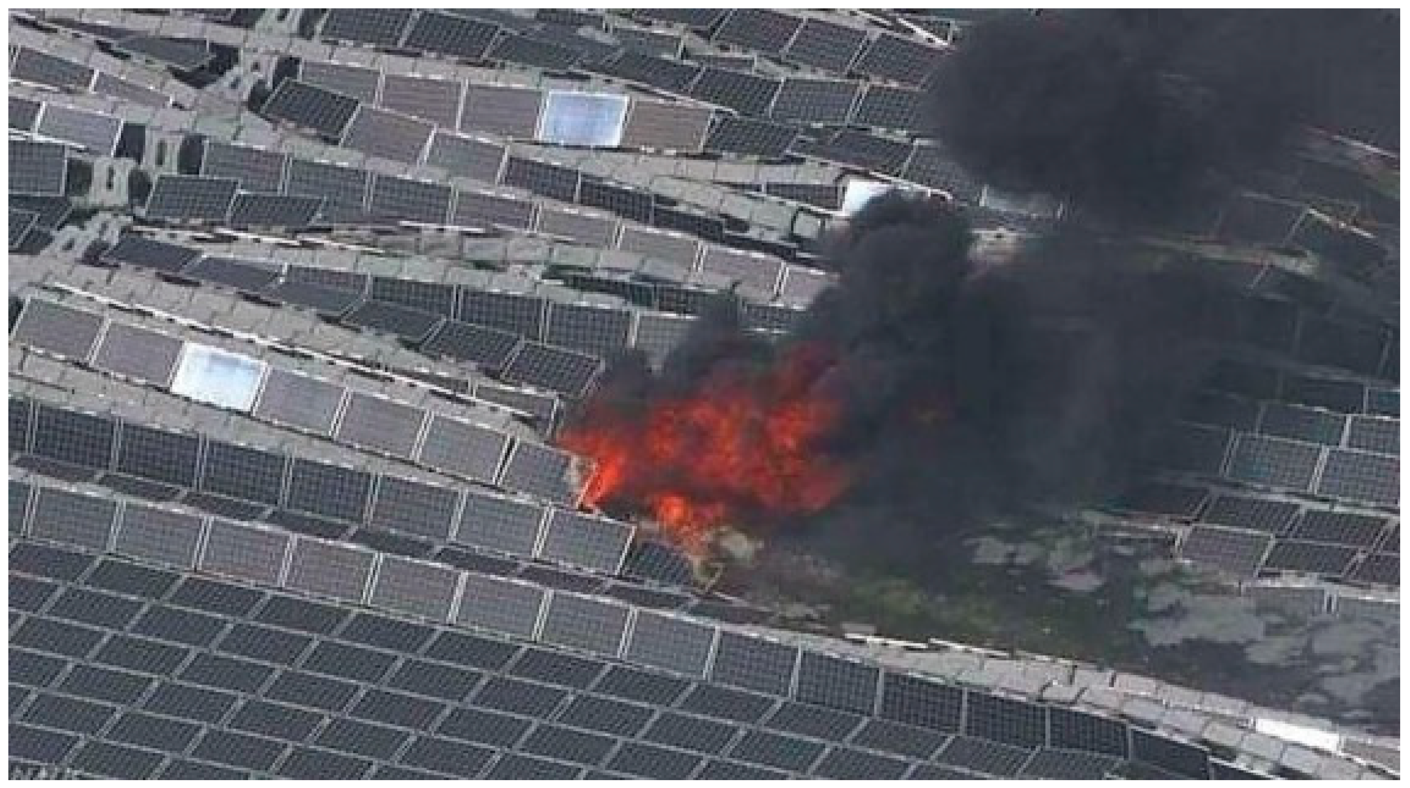
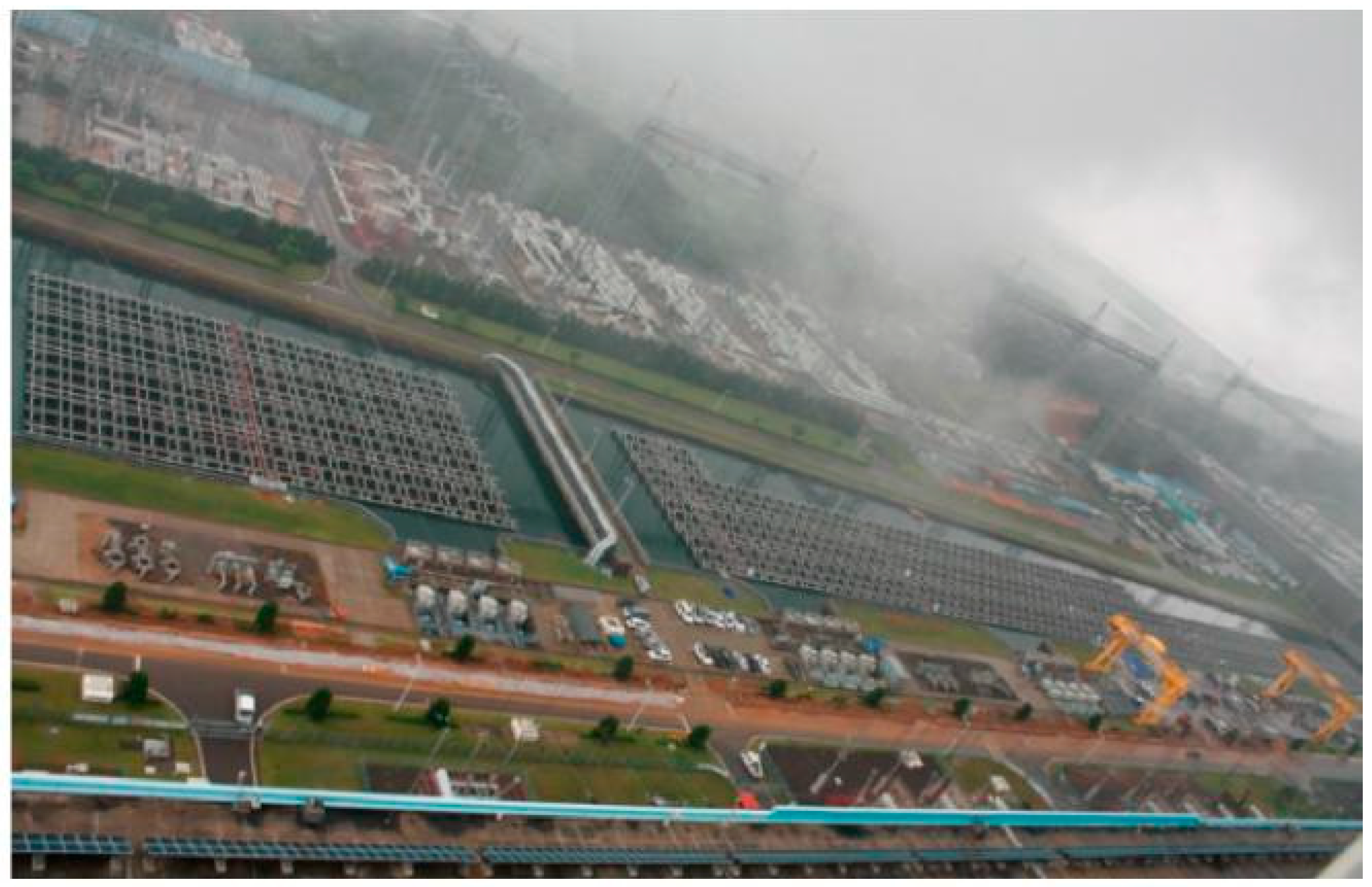
Despite their advantages, FPVs can be subject to harsh environmental conditions when deployed. FPVs can be exposed to wave and wind-induced forces, which can significantly impact the hydrodynamics and structural integrity of these systems, in turn affecting their performance. This is evidenced by the accident that occurred at a FPV farm in Japan [
23], as shown in
Figure 1. Hence, it is imperative to design FPVs that can withstand these harsh environmental conditions. Experiments can be performed to understand the behaviour of FPVs before deployment. However, conducting such experiments would require an extensive setup, including a wave tank, motion-tracking cameras, and mooring systems, which could be time-consuming and costly. Additionally, experiments are limited by the size of the facilities. Hence, computational studies are gaining increasing popularity in analysing the performance of FPVs.
The following literature review focuses on advancements in computational techniques for analysing the performance of photovoltaic (PV) systems. Specifically, the review analyses the effectiveness of Computational Fluid Dynamics (CFD) solvers and potential flow solvers in predicting the performance of FPVs subject to wave and wind loads. Various modelling techniques adopted within the framework are discussed and assessed. Subsequently, the review discusses the advantages and disadvantages of each methodology, as well as the research gaps that need to be addressed. The paper is divided into the following sections:
Section 2 deals with the classification of FPVs.
Section 3 and
Section 4 review existing literature on FPV studies employing CFD and potential flow solvers.
Section 5 introduces the combination of these two solvers. Finally,
Section 6 summarises the review and provides concluding remarks.
2. Symmetrical Design of FPV
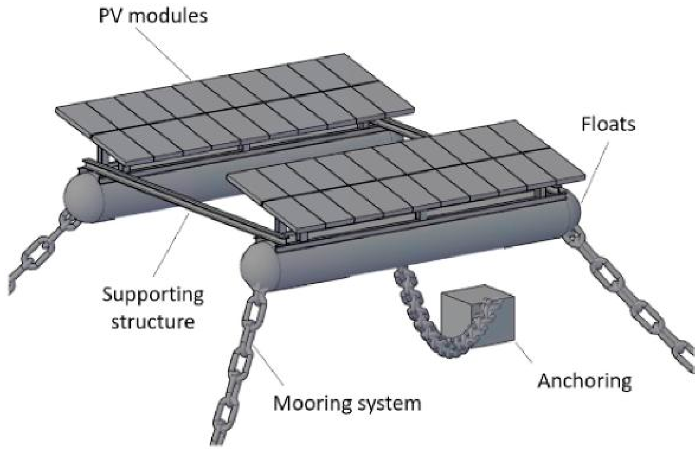
Figure 2 illustrates the typical parts of an FPV unit. The design of an FPV unit is characterised by five components: (a) the Pontoon, (b) the mooring system, (c) the PV panel, (d) the supporting structure, and (e) the anchoring. They are usually symmetrical, consisting of individual modules.
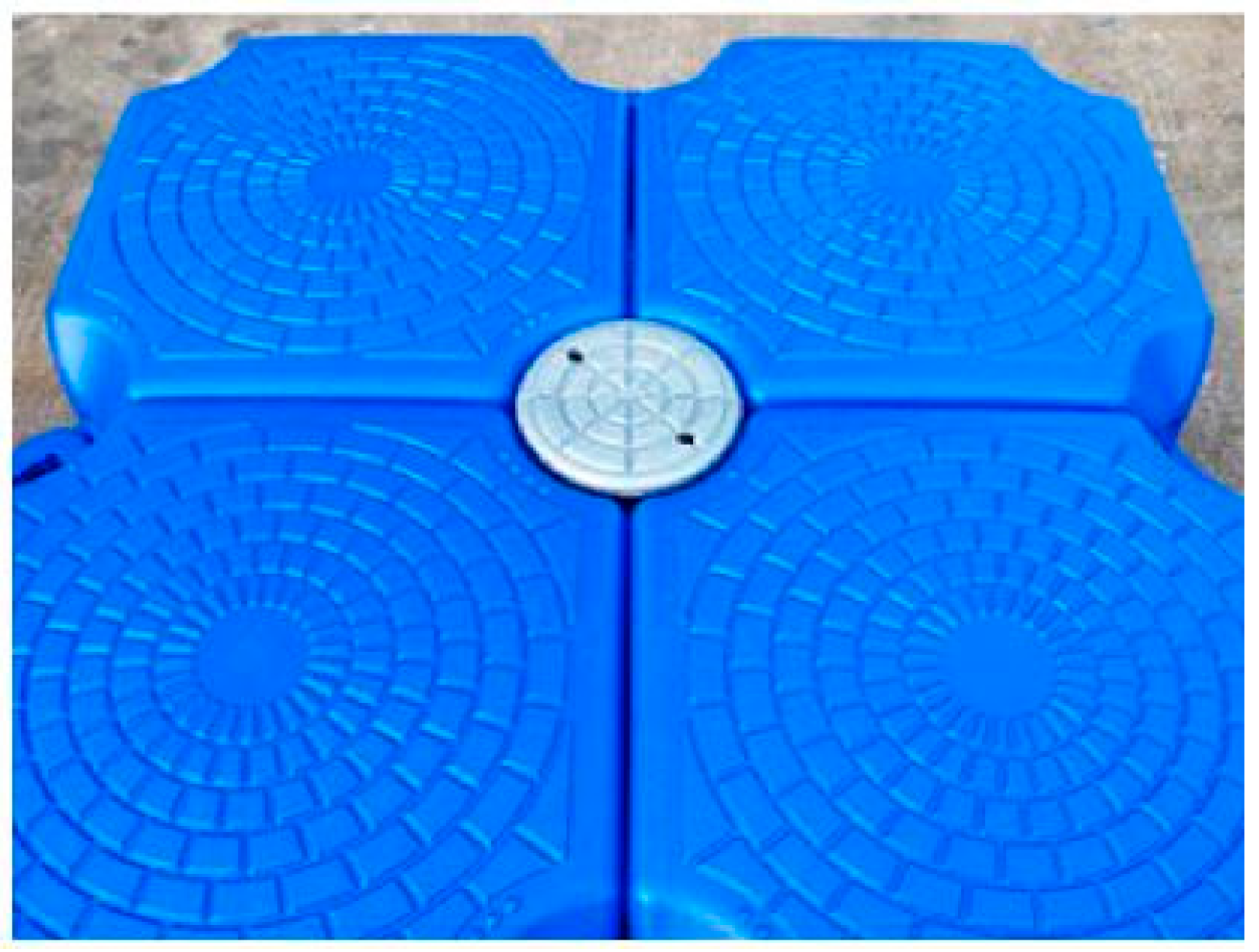
The pontoon plays a vital role in the overall system. It serves as both a mounting surface for a PV panel and a source of buoyancy required to keep the PV afloat. Pontoons typically withstand the majority of environmental loads and provide the primary attachment point for mooring lines. Consequently, pontoons must exhibit excellent resistance to UV irradiation, biofouling and corrosion. The most popular material used is HDPE due to its durability, mechanical strength and UV resistance [
25]. Alternatively, Glass-fibre-reinforced plastic (GRP) can also be employed [
26]. An example of such a pontoon is in
Figure 3.
Mooring is a crucial component of an FPV installation. The purpose of a mooring system is to prevent overturning, inter-unit collision, and unintentional drift [
27]. A mooring system can be characterised into four types: catenary, compliant, taut, and rigid mooring. The mooring lines are subsequently anchored to the ground with the help of dead weights or helical anchors [
25]. The material used here is Nylon ropes, chains or polyester ropes.
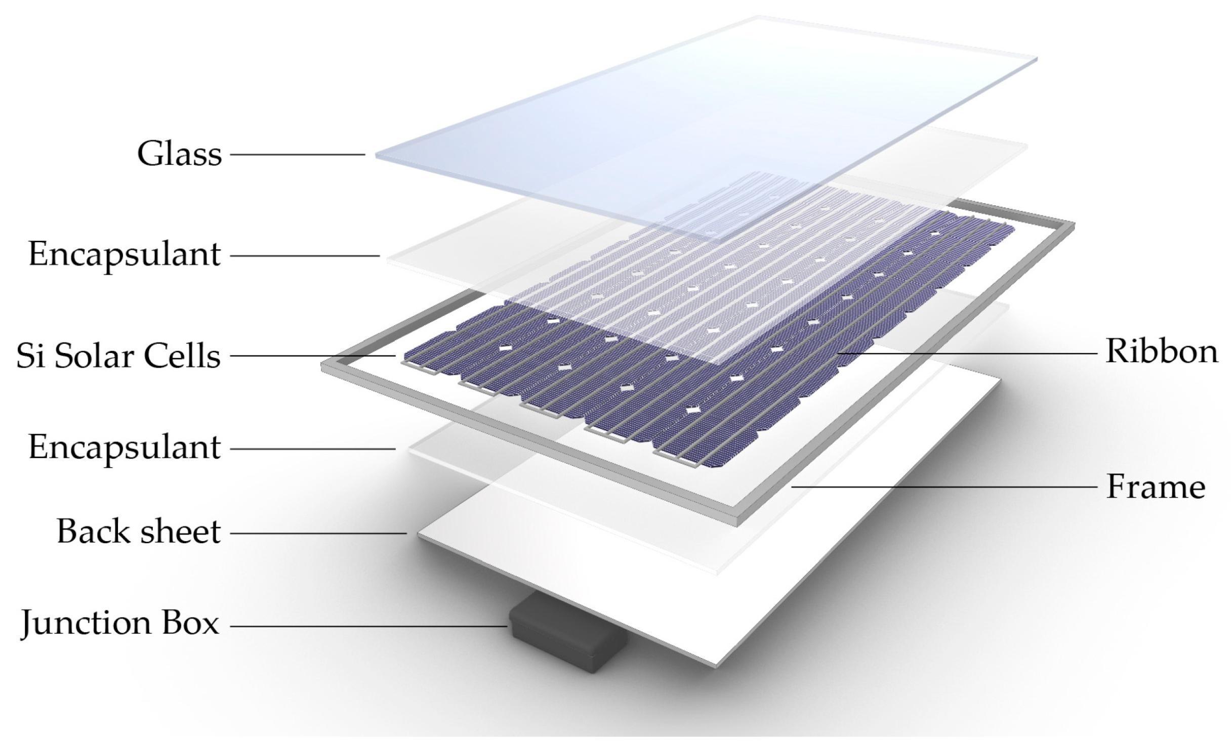
Figure 4 depicts the construction of a PV panel. A PV panel is the principal energy-generating component of an FPV. It consists of a protective glass that acts as a primary protective layer. This glass must be transparent to allow sunlight penetration and protect the PV. A low-iron glass of thickness 3 mm is used [
28]. An encapsulant is employed to combine the PV cells and the protective glass into a single unit, providing additional protection. Within the encapsulant, PV cells are interconnected in series and/or parallel to meet voltage and current requirements. Popular cell types include Perovskite Solar Cells, Dye-Sensitised Solar Cells (DSSCs) and Quantum Dot-Sensitised Solar Cells (QDSSCs). A backsheet is used to provide electrical safety through insulation [
29]. A metallic structure is often employed to support the PV panel. Fibre-reinforced polymer is selected over steel to construct the supporting structure owing to its corrosion resistance against seawater.
In addition to FPV arrays, an FPV farm layout typically consists of power cables, which can be underwater or above water and an inverter. These components transmit the electrical energy generated to offshore distribution networks.
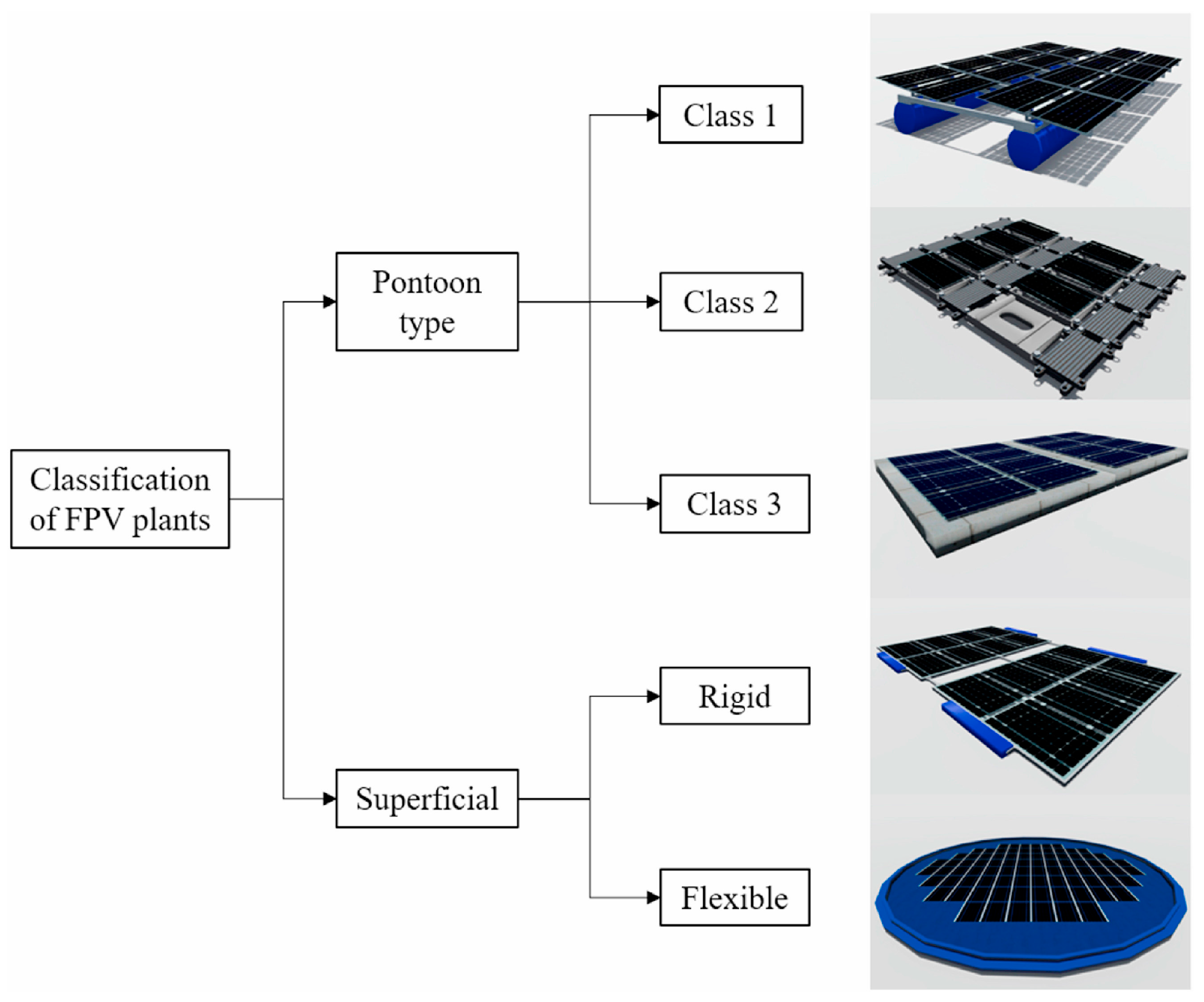
Figure 5 demonstrates the systemic classification of FPV. They are broadly classified into two types: Pontoon and Superficial [
25]. Pontoon-type floating photovoltaic systems (FPVs) provide a stable platform to support photovoltaic (PV) panels. A pontoon-type floating solar system raises the location of solar panels above the water’s surface. The motion response of an FPV is heavily characterised by the type of pontoon and the connection mechanisms that exist between the pontoons. Additionally, the pontoon is subjected to harsh environmental loads. Hence, the design of the pontoon and the type of connection need to be considered. Consequently, the pontoon-type FPV is further classified into three categories: Class 1, Class 2, and Class 3.
Figure 6 represents a class 1 FPV farm. A class 1 type FPV represents one of the earliest iterations of FPVs. Here, the PV panel is supported on cylindrical rafts. This type of FPV construction has its limitations. Due to the nature of the pontoon design, the FPV can be subjected to excessive flexural moment. Furthermore, they can withstand wave heights of up to 2 m [
30], making them unsuitable for deployment in offshore locations. Such a system cannot be deployed in offshore locations where conditions can be severe.
In a Class 2 type FPV, each PV panel has a dedicated pontoon used to provide buoyancy. An array of such FPVs is connected using hinge pins and numerous other connection mechanisms. Compared to a Class 1 category, a Class 2 FPV raises the panel’s height significantly above the water’s surface. To deploy this class of FPVs in nearshore and offshore conditions, the pontoon needs to be designed to withstand elevated wave heights. One of the first class 2 FPV systems was the Hydrelio [
32], developed by the French company Ciel et Terre in 2011. Another example of such a system is provided in [
33].
A Class 3 FPV consists of PV panels supported by a large, rigid platform. If designed properly, this kind of system can provide enhanced stability compared to other FPV types. The presence of a large platform facilitates easier maintenance. However, special attention needs to be paid to the durability of such a system because it will be subjected to severe wind and wave loading. Furthermore, such a construction is expensive to build, making economic viability uncertain.
The second broad classification is the superficial type of FPV. Here, the FPV remains submerged under a thin film of water. This setup helps protect the FPV from wind loads and can provide additional cooling and self-cleaning properties. However, the incident solar energy is reduced due to the presence of water. Within this classification, two types have been identified—rigid and flexible FPVs. Examples of superficial FPVs can be found in [
34].
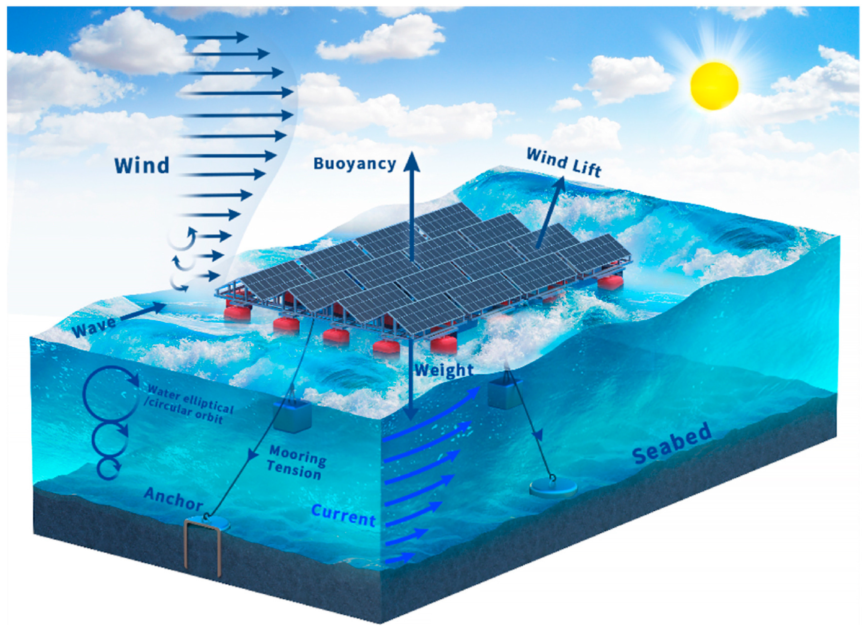
Among the various environmental loads acting on an FPV, as shown in
Figure 7, wind plays a crucial role in the design of photovoltaics, whether they are deployed on land or at sea. Panels are exposed to intense winds, whose impact stresses solar panels, frames, connectors, and other such components. Failure to consider these forces in the design process can compromise the stability of a floating solar farm, potentially leading to accidents and resulting in severe damage and financial losses. Owing to their installation location, FPVs face an increased challenge from wind loads. The motion response of an FPV changes with a change in wind magnitude and direction. This can have a notable impact on the hydrodynamics of the FPV and its mooring system. To prevent such disasters, engineers must evaluate how various parameters, such as tilt angle, array orientation, wind magnitude, and FPV motion, affect the performance of the FPV. CFD can help meet these analysis requirements.
3. CFD-Based Simulations
Traditional simple equations (such as fluid drag equations ) are insufficient for directly estimating the forces and dynamics of an FPV. Numerous factors must be taken into consideration, such as the geometry of floating structures. CFD can play a vital role in bridging these gaps. CFD simulations can indeed support a detailed analysis of induced forces, pressure contours, velocity and pressure flow field. Such information can provide valuable insights into the stability of FPVs.
Understanding FPV aerodynamics necessitates recognising how flow complexity increases from a single FPV to an array of FPVs. Limited studies have been conducted on predicting the aerodynamics of FPVs under realistic marine conditions, particularly in calculating the forces, analysing the pressure distributions on the FPV, and studying the flow patterns, which collectively aid in the design process of FPVs.
To facilitate an accurate analysis of existing research, it is essential to examine the computational settings employed by different studies. A thorough analysis reveals that the kωSST (Shear stress transport) model emerges as the predominant model. This preference can be attributed to several key advantages. The SST model is a combination of the k-ω and k-ε models, utilising the k-ω model in the near-wall regions where viscous effects dominate, and the k-ε model in the free-stream regions. This approach is beneficial as it accurately captures boundary layer development, which is crucial for predicting separation points and pressure distributions, while maintaining accuracy in the wake region where complex interactions occur. Additionally, the kωSST model demonstrates good performance in adverse pressure gradient flows, which are commonly encountered around bluff bodies, such as FPVs. A study by [
37] employed the Reynolds stress model (RSM), which solves six transport equations for all components of the Reynolds stress tensor, thereby helping to capture anisotropic turbulence. This improves the accuracy of the results obtained; however, it solves five more transport equations compared to the kωSST model, thereby significantly increasing the computational time. Additionally, a previous study [
38] adopted the Large Eddy Simulation (LES) model. LES directly resolves the larger scales and models the smaller scales of turbulence. While LES provides valuable insights into flow physics, this method also imposes significant computational demands, particularly with finer mesh resolutions. For engineering design, analysis, and deployment, striking a balance between accuracy and speed is crucial. kωSST efficiently meets these requirements and is, therefore, widely adopted.
Similarly, two pressure-velocity coupling methods have been adopted: the Semi-Implicit Method for Pressure-Linked Equations (SIMPLE) and the Pressure Implicit with Splitting of Operators (PISO). While SIMPLE provides a stable approach for an iterative correction procedure for pressure and velocity fields, PISO offers better accuracy due to its predictor-corrector methodology. This method becomes advantageous while studying wake interactions for an array of FPVs. Another critical factor is the domain’s boundary conditions. Upon analysing existing studies, noticeable differences are found in the sidewall implementation. To model an open marine environment accurately, sidewall effects must be negligible to avoid flow constraints. Three boundary conditions are adopted: slip, symmetry, and periodic. Slip and symmetry boundary conditions impose zero normal velocity and normal gradients at the boundary, preventing non-physical flow constraints. Similarly, as the distance from the area of interest increases, the flow gradients normal to the sidewall approach zero, behaving in a manner analogous to symmetry and slip conditions. Hence, all three boundary conditions, when located sufficiently distant from the area of interest, behave like frictionless walls, achieving the objective of modelling an open marine environment.
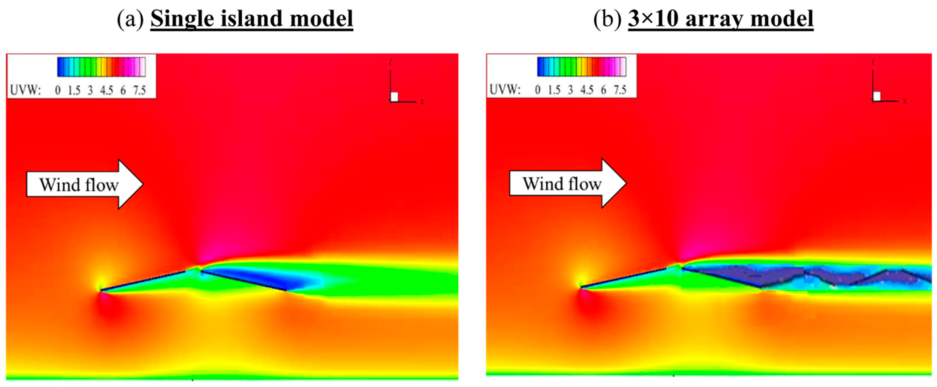
The computational methodologies discussed above enable investigations of flow structures. Understanding these flow patterns is crucial for predicting forces, optimising panel arrangement, and ensuring structural integrity. To understand the flow physics, it is essential to understand the differences between a single FPV module and an array. A CFD analysis [
38] discusses the differences in flow patterns between a single FPV module and a 3 × 10 array.
Figure 8 illustrates the contrasting flow patterns of a single FPV module and an FPV array.
We can observe that the downstream FPV falls under the wake region of the upstream FPV. This can change the pressure distribution of the FPVs in the wake region compared to the single FPV module. This demonstrates why single-panel aerodynamic data cannot be directly extrapolated to predict aerodynamic properties of the array. The sheltered FPV experience reduced wind velocities and altered pressure distributions, resulting in modified force coefficients and dynamic responses.
A common strategy for reducing computational geometry involves analysing a 2D section of a 3D domain. This strategy, adopted by [
39,
40], offers computational advantages, reducing simulation time by orders of magnitude compared to a 3D domain. While this assumption provides a fundamental understanding of boundary layer development and flow separation, it fails to capture three-dimensional effects such as edge flows and vortices, which influence spanwise pressure distributions and, consequently, aerodynamic loads. The limitations of dimension simplification are investigated by [
41].
Figure 9 illustrates the various types of computational domains examined by the study.
The analysis revealed that the 2D domain failed to capture any 3D effects. The 2.5D domain captured the spanwise turbulence but was unable to capture the tip vortices.
Figure 10 illustrates the reattachment point for different domains. Compared to the 3D domain, reattachment of flow is delayed in the 2D and 2.5D domains. Consequently, the SYM-3D domain accurately predicts the reattachment point, which enables the accurate calculation of aerodynamic forces.
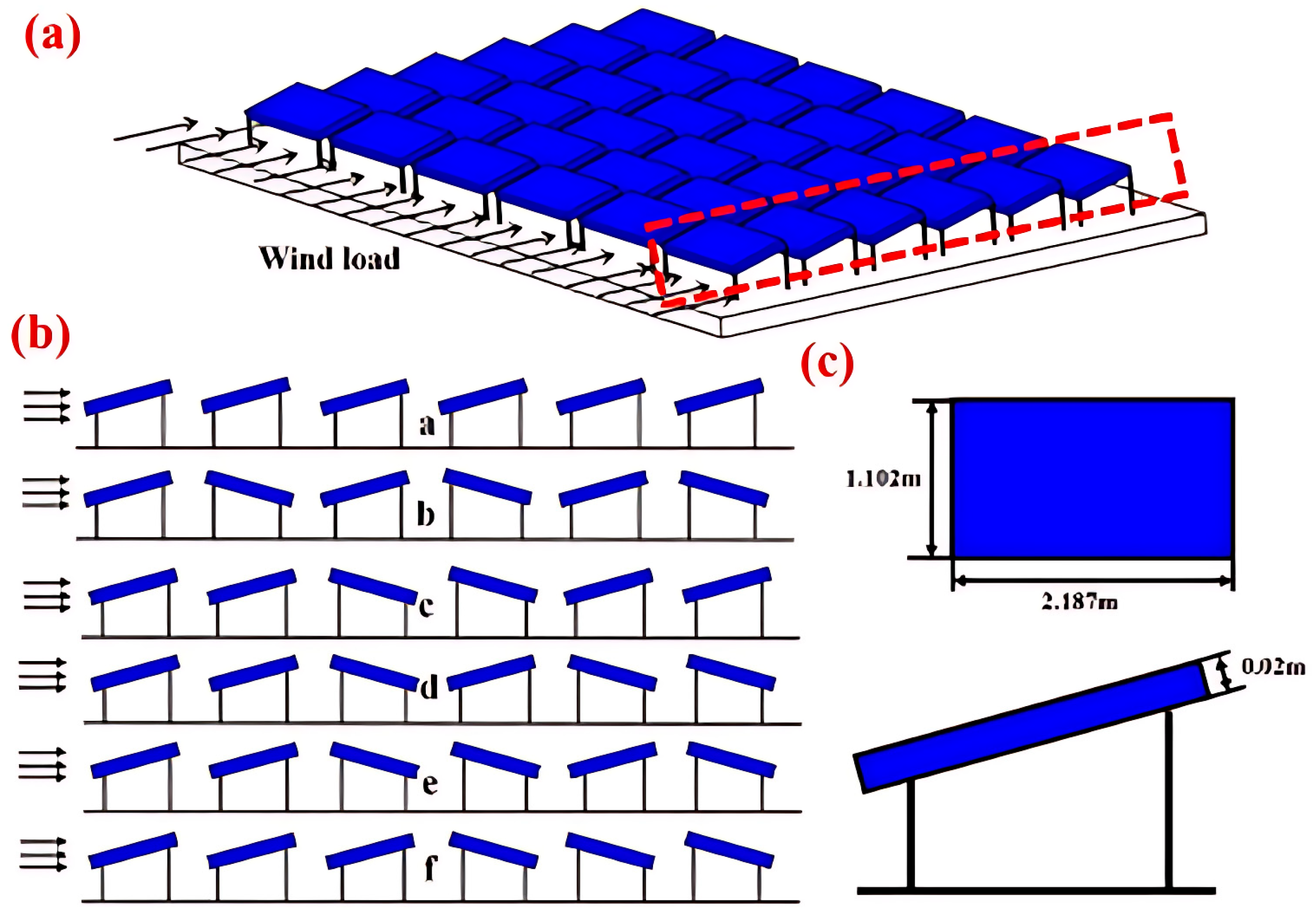
Another essential consideration influencing FPV aerodynamics is the spatial arrangement and configuration of solar panels within the array system. The angular orientations within the array system influence the flow field characteristics. A previous study by [
37] analysed the influence of panel orientation on the aerodynamic behaviour of the FPV.
Figure 11 illustrates the arrangement adopted
Figure 11a is the standard configuration adopted by most studies.
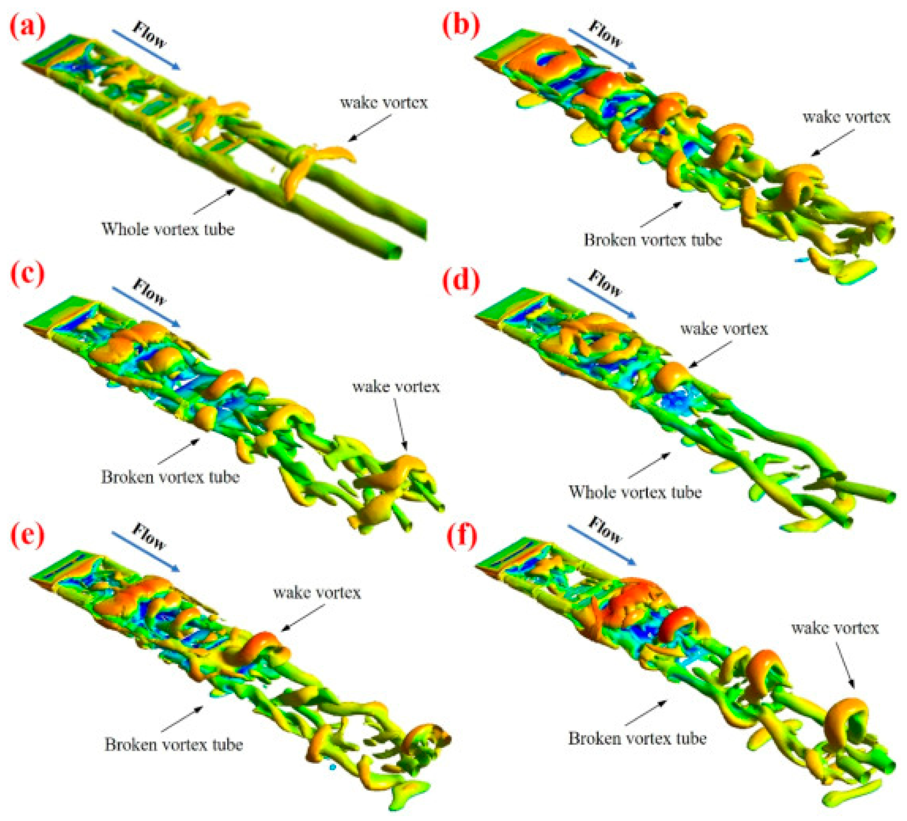
Figure 12 illustrates the vortex structures originating from the interaction of wind with the solar panel [
37]. Two vortices characterise flow structures from an FPV—one is the edge vortex, which is typically found in the form of cylindrical tubes, and wake vortices, which originate from the flow separation which occurs from the upper edge of the FPV panel. The sharp geometric discontinuity generates complex three-dimensional structures. In
Figure 12a, this wake vortex grows, and in other cases, where the panel arrangement is anisotropic, the vortices break and interact with each other. The anisotropic arrangement promotes the development of recirculation zones for each panel, which in turn leads to vortex shedding which promotes the growth of recirculation zones for each panel, which, in turn, leads to vortex shedding.
Previous studies have only considered the PV panel, ignoring the pontoon and frame for geometric simplification. However, their presence has a strong influence on the aerodynamics of the FPV. Previous research [
42] investigated the effect of pontoon on the aerodynamic properties of the FPV. The analysis revealed that the presence of a pontoon significantly reduced the impingement on the backside of the panel, which in turn can reduce the flow-driven pressure force.
After establishing the flow structures originating from wind-FPV interactions, understanding the relationship between the flow physics and the aerodynamic forces acting on the FPV. The transition from flow field analysis to force analysis is a critical step in the design process, as force and pressure distributions directly inform engineering calculations and safety assessments. A recent study [
39] used the CFD software flow simulation to analyse the aerodynamic load acting on an FPV. The study adopted a 2D computational domain to reduce computational requirements. The findings reveal that the downstream FPV experienced significantly reduced loading due to the sheltering effect provided by upstream units. This sheltering effect occurs as the windward FPV creates a wake region, which is characterised by reduced velocities. Additionally, an investigation by [
40] analysed the impact of a floating object in front of the FPV array, and observed that the floater provided a shielding effect, and the FPV array experienced similar drag forces. However, a comprehensive study by [
41], comparing 2D and 2.5D domains with 3D domains found that the 2D and 2.5D domains significantly overestimate the coefficients of lift and drag, respectively. In the 2D and 2.5D domains, the flow reattachment is delayed, which expands the separation bubble. This exposes an increased area of the geometry to the low-pressure separated flow, thereby increasing the drag and lift forces. These findings reveal a fundamental limitation of adopting a 2D computational domain for the design process of FPVs.
Numerous studies have been performed using 3D domains. An extensive analysis by [
43] investigated using analytical methods to measure forces against CFD simulations, and the study demonstrated that the analytical techniques significantly overestimate the aerodynamic loading characteristics on the FPV. This is because the analytical equations fail to account for the complex flow structures as previously discussed, highlighting the need to employ computational techniques to quantify wind loading. Previous studies [
24,
44] investigated the sheltering effect and found that the upstream FPVs experience higher aerodynamic loads compared to the downstream FPVs. Study by [
42] revealed that the velocity is decreased by half for the downstream components due to the shielding effect of the first FPV. Furthermore, the study investigated the impact of a pontoon, and the findings revealed that the presence of a pontoon significantly reduced the load acting on the PV. However, a previous investigation by [
45] reported a higher aerodynamic load for the second FPV. This contrasting behaviour can be attributed to the FPV type, wind conditions, and the gap between the floater arrays. This contradictory result underscores the sensitivity of FPV aerodynamics, and the shielding effect is dependent on the FPV array configuration and environmental conditions. A recent study by [
37] investigated the forces acting on distinct PV orientations as seen in
Figure 11. The findings revealed that the drag coefficient remained consistent across all configurations, however, a significant improvement was observed in the coefficient of lift with an anisotropic arrangement. These results suggest that manipulating panel orientation offers aerodynamic optimisation without compromising the system’s drag, thereby providing stability to the overall system.
The analysis of existing literature provides guidance for conducting accurate FPV simulations. The critical finding emerging from the studies is that all components of an FPV system, including PV panels, pontoons, and supporting frames, play a vital role in determining the overall characteristics. This understanding is crucial when predicting the behaviour of large-scale commercial FPV installations. The cumulative effects of component-level contributions can combine to exert substantial influence on the overall system stability.
In an open marine environment, waves play a crucial role in the hydrodynamics of FPV systems, influencing the system’s motion response. Understanding and accommodating these motions during the design stages helps ensure the stability, longevity, and energy yield of FPV systems.
A CFD analysis by [
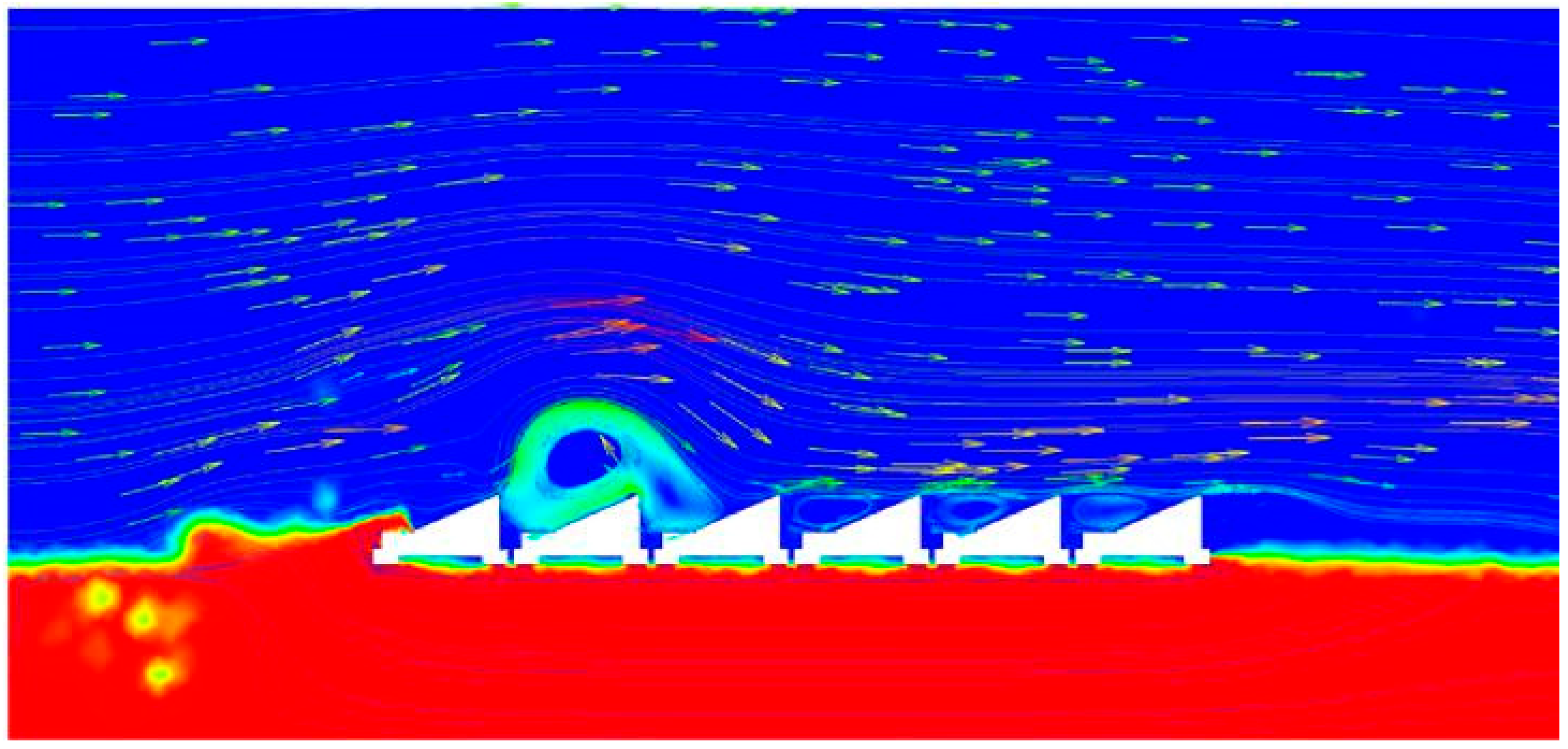
46] focused on a 2D study on a single row of an FPV using ANSYS Fluent, investigating the effect of combined wave and wind loads on the FPV.
Figure 13 illustrates the wave and wind streamlines. The findings revealed that the wind’s effect causes significant wave decay, resulting in greater pressure at the front of the FPV platform compared to the rear. However, to understand the true nature of loads acting on the FPV, a 3D geometry and domain must be taken into consideration.
Twin cylinders have emerged as a popular pontoon type, often being deployed as Class 1 FPVs. A study by [
47] conducted CFD simulations on the FPV platform is shaped in the form of large cylindrical pipe structures using ANSYS Fluent. It was found that the surge, heave, and pitch response amplitude operators (RAOs) are directly proportional to the wave height and inversely proportional to the wavelength. Furthermore, increasing the diameter of the cylindrical pipes increases hydrodynamic forces. The forces were validated against Morrison’s equation in MATLAB. CFD results showed good agreement. Similarly, previous study [
48] investigated the performance of a twin-cylinder FPV platform using the open-source CFD code OpenFOAM. MATLAB was used to generate irregular waves and transfer it to OpenFOAM. A validation study was conducted, and subsequently, its performance under irregular wave regimes was investigated. The findings revealed the presence of higher-order harmonics, which can help identify susceptibility to resonance. The peak RAO motion and Force are underrepresented in the irregular wave regimes. This behaviour can be attributed to errors in the experiment. However, this study has not performed any mesh convergence studies, which play a crucial role in the verification and validation process. Results indicated that the turbulent flow between the gaps of the cylinders plays a vital role in hydrodynamics. The findings demonstrate the suitability of twin-cylinder platforms in calm and moderate conditions, making them ideal for deployment in inland and nearshore locations. However, further analysis under extreme sea states is required before deployment in offshore locations.
A recent study by [
49] conducted CFD simulations to investigate the performance of a floating solar farm. The CFD commercial software STAR-CCM+ was employed for this study. Each unit of the FPV system consisted of 9 FPV modules in a 3 × 3 arrangement. The floating solar farm was made of a 2 × 2 array of these units. A revolute hinge connector was used to connect the units. This can be categorised as a class 2 FPV. The results indicated that the RAO pitch and RAO heave were directly proportional to the wavelength and wave height, which is an inverse trend compared to the twin-cylinder FPV [
47]. The magnitude of the RAO values varied across the unit floaters. However, the differences between the FPV units reduced with increasing wavelength.
Class 3 FPVs face a fundamental design challenge: maintaining structural integrity under extreme wave loads while minimising motion response. A focused study [
50] investigated hexagon-shaped flexible photovoltaic foundation column with ANSYS Fluent and identified wave incidence angle as a dominant parameter, with a maximum force occurring at 30° incidence. Furthermore, the results indicated that the load increased with increasing depth, with the leading foundation experiencing higher impact loads. This finding is crucial for mooring design and foundation sizing in deeper waters where class 3 FPVs are typically deployed. Additionally, a recent study [
51] performed CFD simulations comparing the motion of a hexagonal FPV platform and a SPAR-type FPV platform, developed by the US Navy research team. The findings revealed that the SPAR-type FPV platform depicted a reduced motion response compared to the hexagonal platform. However, a detailed study on the impact of wave loads on the SPAR platform would be beneficial in providing insights into the performance of such a design and comparing it against other platform types.
An extensive study by [
52] conducted CFD simulations to analyse the hydrodynamic performance of a novel sun-tracking FPV system (Class 2) coupled with a breakwater. To implement this, a sliding mesh technique with a constant velocity was employed. A nested sliding mesh technique was employed in this study, with a prescribed velocity determining the rotation of the FPV. The findings revealed that the breakwater reduced the wave height by 40%. Additionally, the use of mooring reduced the pitch by 12.5%. However, the current study was conducted at a wave frequency of 0.91 Hz and a wave height of 0.1 m. The rotation of the FPV did not influence the flow field around the FPV. A detailed study over a wider range of wave conditions can provide a deeper insight into the performance of the sun-tracking FPV system. Furthermore, owing to the unique nature of this FPV, validation of this technique can aid in establishing the procedure to model such systems in the future.
A comprehensive study by [
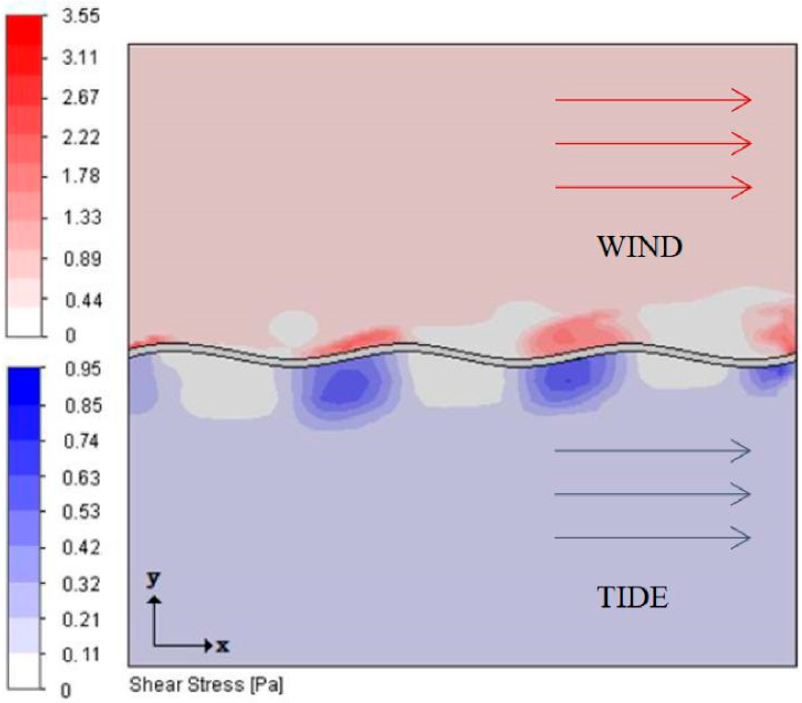
53] investigated the forces acting on a distinct, thin film flexible FPV, under the influence of wind and current.
Figure 14 illustrates the shear stress acting on a thin film FPV. The study highlighted the yielding nature of a thin, flexible composite FPV, flexing with waves rather than opposing them. The results revealed that the mooring load was significantly reduced for the same installation rating as a wave energy converter. However, in extreme weather conditions, the PV array was fully submerged, rendering it unsuitable for open-sea environments. Previous research [
54] investigated the effect of draught, water velocity and number of bodies on the drag of FPV structures. Furthermore, the flow field characteristics around FPVs were examined with ANSYS Fluent. Results indicated that the draught has a significant contribution to the drag experienced by the system compared to the water velocity. This is because of the increased pressure difference between the front and back sides. The front FPV provided a shielding effect, which reduced drag for the subsequent bodies. With an increasing number of bodies, the vorticity at the leeward side of the front FPV was reduced. Hence, the drag of an FPV unit decreases with a rising number of bodies. However, the drag of the total system still increases with the addition of more FPVs. Like aerodynamic loads, these findings are critical in mooring design. The total drag of the system is a combination of wind and current loads, which determine the overall stability of the system. Additionally, a comprehensive analysis by [
55] revealed that when the direction of air and currents was identical, there was a reduction in temperature. Consequently, when the directions were reversed, there was an increase of 0.8 °C.
From the above literature, we can identify significant limitations in modelling FPV hydrodynamics using traditional CFD techniques. Many studies do not accurately represent the scale of FPVs. Furthermore, modelling approaches include assuming many FPVs as one FPV, which can underestimate the hydrodynamics of FPVs. Additionally, there is a lack of validation studies, which need to be addressed to develop a reliable system.
4. Potential-Flow-Based Simulations
While CFD-based studies provide detailed insights into the behaviour of FPV systems, potential flow-based solvers offer an alternative approach for analysing the hydrodynamic behaviour of FPVs. Potential flow assumes the fluid to be inviscid, incompressible and irrotational. The advantage of the potential flow method lies in its computational efficiency. This computational efficiency permits studies of FPV arrays, which enable a better understanding of inter-FPV interactions that would be expensive to analyse using traditional CFD solvers.
Potential flow theory provides a well-established framework for analysing FPV hydrodynamics. The three-dimensional flow field is represented by a velocity potential that satisfies the Laplace equation. The total velocity potential is decomposed into three fundamental components: incident wave potential, diffraction potential and radiation potential. The two most popular potential flow software packages are ANSYS AQWA and OrcaFlex. Numerous studies [
56,
57,
58,
59,
60,
61] employ ANSYS AQWA to analyse the hydrodynamics of FPVs. OrcaFlex is employed by [
62,
63].
Researchers have adopted multiple computational strategies using potential flow solvers to predict the hydrodynamics of FPVs. However, a significant limitation encountered in FPV modelling is the grid limit imposed by ANSYS AQWA. To address this limitation, studies in [
56,
57,
61] have employed the ‘waterline’ method, wherein only the geometry of the FPV submerged below the water is considered for the analysis, while the structure above the waterline is ignored from the computational domain. While this strategy helps overcome this drawback, its validity depends on the assumption that the geometry above the waterline does not significantly impact the hydrodynamics. This condition is typically satisfied when the angle of inclination of the panel remains low, preventing any substantial impact on the metacentric height and overall stability of the floating system. The applicability of the waterline method is geometry-dependent, particularly in the cases of Class 2 and Class 3 FPVs, where structures above the waterline significantly influence the overall system response. A fundamental limitation of potential flow solvers is their inability to incorporate viscous damping, which can lead to an overestimation of motions. To address this limitation, Numerous studies [
64,
65] incorporated viscous damping within the potential flow solver. A previous study [
64] obtained the viscous damping through heave decay tests performed using STAR CCM++. Conversely, [
65] obtained the additional damping from experimental data, utilising empirical measurements to calibrate the potential flow model.
A comprehensive investigation by [
62] employed the waterline method in OrcaFlex to analyse the motion of FPV array. To improve computational efficiency, two alternative strategies were proposed—Model A, representing FPVs as individual bodies without connectors, and Model B, treating the FPVs as one single rigid body. These simplified approaches were compared against model R, which represents FPVs interconnected and modelled individually, and serves as a for comparison due to its closest physical representation of an FPV array behaviour. The findings revealed that the Model A slightly overpredicted the heave and pitch motion of the FPV. This behaviour can be attributed to the lack of FPV dynamics, which diminishes motion. Model B slightly underpredicts the heave motion and significantly underpredicts the heave motion. This behaviour can be attributed to the rigid body formulation, which prevents motion and reduces overall system flexibility. Furthermore, Model A is computationally efficient while maintaining reasonable predictive capability. Conversely, a study by [
66] demonstrated that when the incident wavelength exceeds the length of the FPV array, the FPV array can be treated as a single continuous hydroelastic body.
As demonstrated by [
62], connectors and joints play a significant role in the hydrodynamics of FPV arrays. Following these findings, a study by [
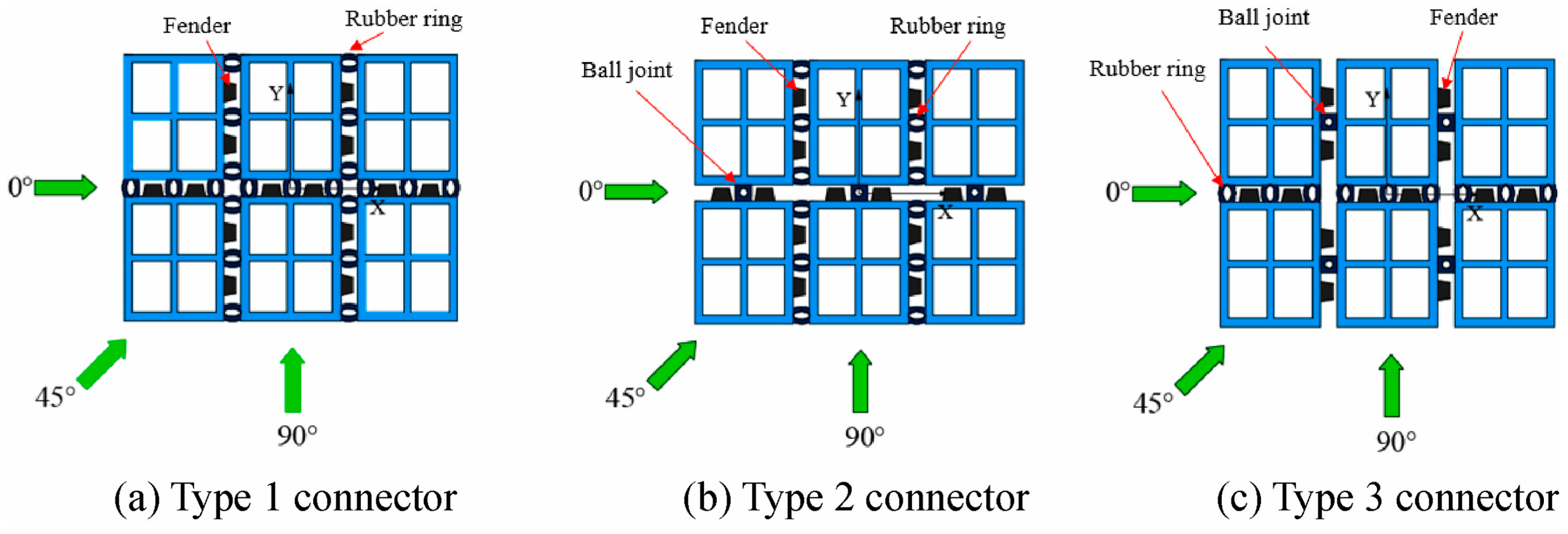
61] investigated different joint systems acting on a rectangular array. Three distinct joints were investigated—Type 1, employing rubber rings; Type 2, employing ball joints in the direction of wave propagation and rubber rings perpendicular; and Type 3, rubber rings in the direction of wave propagation and ball joints perpendicular to it.
Figure 15 illustrates the connectors employed in the study. The findings revealed that type 2 was found to be the most effective in reducing motion response and mooring forces. The ball joint, in the direction of wave propagation, aided in reducing the rotational motion response and increased module interaction, consequently reducing the magnitude of forces transmitted to the mooring system.
Upon investigating the effectiveness of joints, another important parameter influencing FPV performance is the array arrangement. Array configuration determines the module interactions and wave energy dissipation through radiating and diffracting waves. Furthermore, the spatial arrangement influences the operation of the joints, which in turn affects the overall performance of the FPV system. Previous work [
56] investigated three distinct array configurations: Type 1 is a straight-line configuration; Type 2 is a rectangular arrangement; and Type 3 is a honeycomb structure.
Figure 16 illustrates the FPV configurations employed in the study. The findings revealed that the rectangular array demonstrated superior performance in both normal and extreme sea states. This can be attributed to optimal load distribution and favourable wave interference patterns. The honeycomb structure exhibited poor performance in normal sea states, and the linear array showed poor performance in extreme sea states. These findings suggest that the rectangular configuration provides the most robust performance across a full spectrum of operating conditions. However, it is worth noting that this study was conducted under the waterline assumptions. Further research employing the complete geometry could provide comprehensive insights into the optimal design of array configurations.
The pontoon design plays a significant role in the hydrodynamics of FPV. A recent study [
67] investigated the hydrodynamics of an FPV employing tubular-based twin hulls, examining the effect of the wavelength to gap ratio on the performance of the FPV. The study demonstrated that at large wavelengths, the gap effect diminishes, but at short wavelengths, there is a 40% increase in axial force due to the gap effect, showing good agreement with experimental data. However, owing to the limitations imposed by potential flow, the model failed to predict the turbulent and wave-breaking effects between the gaps of the two tubular structures. Similarly, a detailed study [
59] investigated two distinct pontoon types—catamaran-based and semi-submersible pontoon. The analysis revealed that the catamaran showed better seakeeping properties, exhibiting reduced motion response characteristics compared to the semi-submersible. A follow up study by [
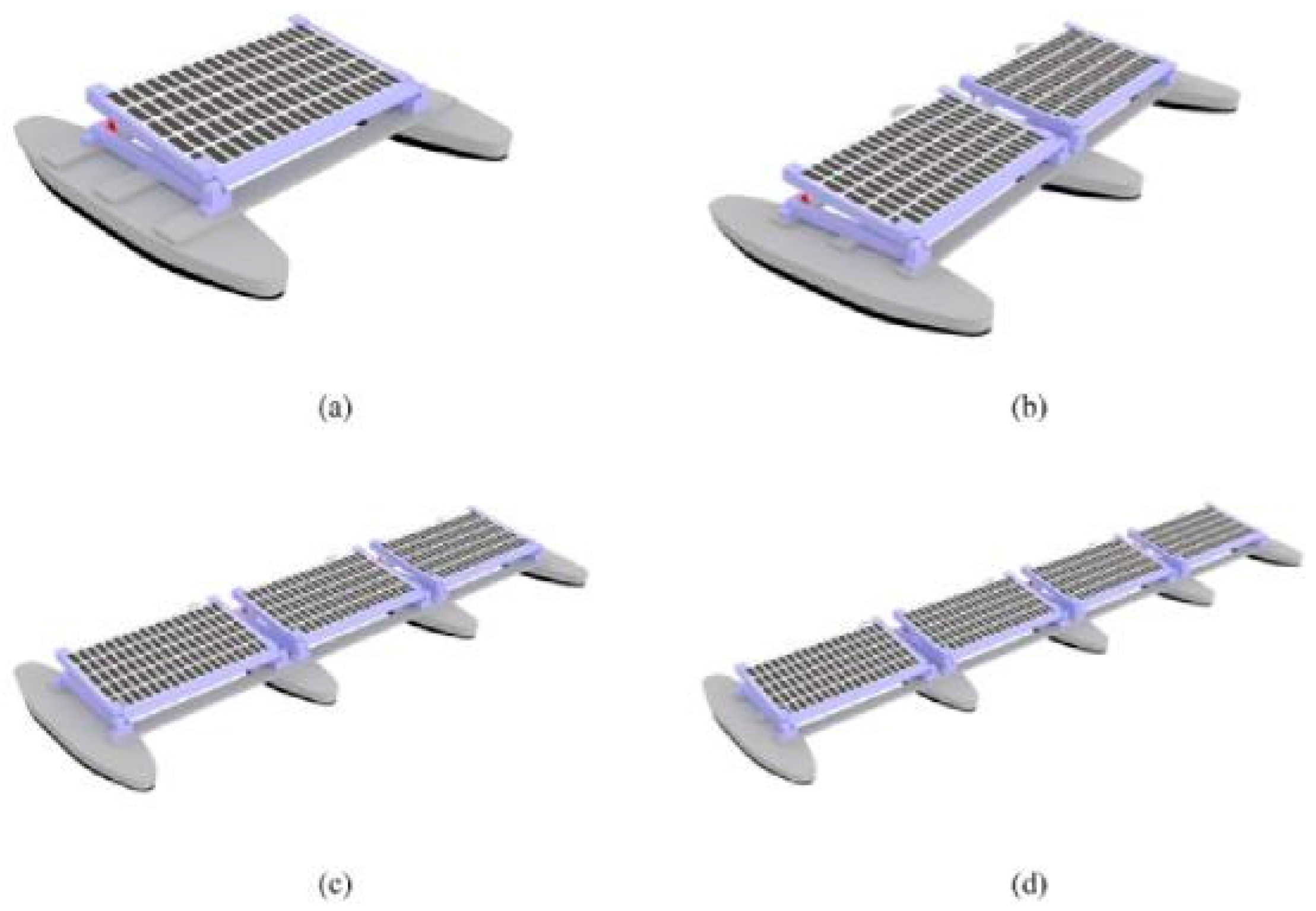
60] analysed the effect of the number of hulls on the stability of the FPV.
Figure 17 illustrates the hull configuration analysed for the investigation.
The findings revealed that as the number of hulls increased, the stability and seakeeping properties of the FPV improved, due to changes in the metacentric height. This relationship suggests that the multihull configuration offers significant advantages. Further research investigating the influence of increasing tubular structures can provide great insights into scaling relationships and help recommend design guidelines for optimising stability performance across FPVs.
Complementing these findings, several studies [
64,
65,
68,
69] systematically investigated different pontoon configurations, demonstrating the importance of pontoon design in determining the FPV hydrodynamic characteristics and establishing pontoon selection as a fundamental in the design optimisation process.
5. Combined-Solvers-Based Simulations
In the previous sections, we have discussed FPV studies incorporating CFD and potential flow solvers. CFD and potential flow solvers show good agreement with experiment when modelling FPV hydrodynamics in normal sea states. Both solvers show good agreement under the following conditions: moderate wave heights with low steepness across all wavelengths, and in the global motion response, where viscous effects remain minimal. Both methods also demonstrate good agreement for mooring forces when modelled under such conditions. Furthermore, strategies such as representing multiple bodies as a single rigid body are a common approach adopted by both solvers across various studies. However, there are some marked differences between the two which stand out. Potential flow does not account for viscous damping effects. This property is crucial while modelling for extreme sea states and in simulations where viscous effects are predominant. Potential flow solvers depend on empirical data to artificially incorporate viscous damping. While CFD accurately models extreme sea states, including turbulence and wave breaking, potential flow lacks these features. Furthermore, CFD enables direct modelling of FPV hydrodynamics, which are crucial for stability. ANSYS AQWA uses analytical equations to implement wind loads, which have been shown to be overestimated in existing CFD studies. However, potential flow has a distinct advantage—computational efficiency. This computational efficiency allows rapid assessment, which is fundamental for initial design studies.
Due to the multiphysics nature of FPV systems, where wave-induced motion, aerodynamic forces and structural deformations are tightly interlinked, some researchers often employ a combination of solvers to capture the full range of interactions. This typically involves combining two or more approaches, such as CFD, potential flow, FEA, or the development of custom hybrid models. This integrated approach enables a holistic understanding of FPV behaviour under combined wind and wave interactions.
A typical computational technique is to use a potential flow solver to obtain the motion of the FPV, which is used as a translational object while analysing the aerodynamic loads of the FPV. This provides an accurate estimate of the structural loads acting on the body due to wind. A comprehensive study [
70] carried out simulations on a unit FPV using ANSYS AQWA to obtain the motion response of FPVs. This motion response data was subsequently transferred to ANSYS Fluent (Version 13) to investigate the aerodynamic performance of the FPV. This coupled method provides excellent insights into the aerodynamic performance under the influence of waves. Furthermore, this coupled approach leverages the computational efficiency of ANSYS AQWA and the modelling capabilities of FLUENT. The results showed that the wave angle significantly influences the motion of an FPV, leading to variations in the tilt angle and roll of the FPV, which in turn impact the lift coefficient and pressure distributions on its surface. Similarly, a detailed study [
71] carried out simulations using ANSYS-AQWA and ANSYS FLUENT, as seen previously in [
70], on an FPV module comprising 20 solar panels arranged in a 5 × 4 configuration. The results showed that under normal conditions, the pitch was within 2°, however, the pitch was significantly higher without overturning, thereby contributing to the increased surge motion of the module. Additionally, the findings revealed that the wind force is the dominant factor affecting the mooring force.
A rigorous study [
45] simulated a floating solar farm by considering the wave and wind loads. Initially, wind-induced force distribution was obtained and then transferred to the FEA solver. Similarly, the motion response of the FPV system under waves was obtained and transferred to an FEA solver. These two solutions served as boundary conditions for performing a stress analysis. The findings revealed regions of significant stress at the junction of the pontoon and solar panel.
A pioneering study [
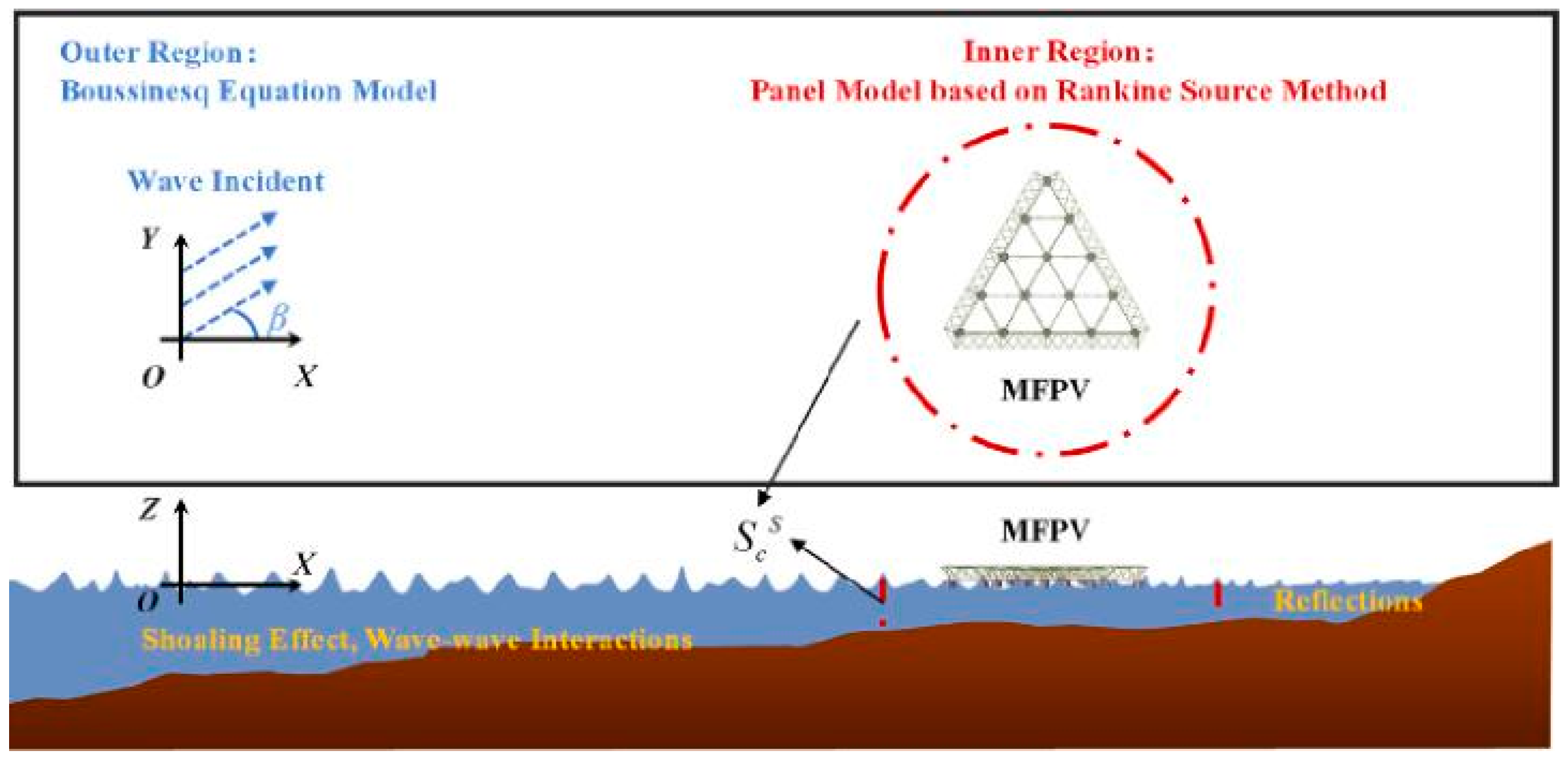
72] performed simulations investigating the effect of seabed configuration, breakwater location and location within the bay. A novel technique, termed the ‘Hybrid Boussinesq Panel method (HBPM)’, was introduced. In this method, as illustrated in
Figure 18, the domain is divided into two regions: (1) the outer region, characterised by wave propagation using the nonlinear Boussinesq model FUNWAVE-TVD, and (2) the inner region, which employs potential flow and the panel method. It was shown that an FPV should be placed close to the breakwater, avoiding areas near the mouth of the bay.
The four studies highlighted above demonstrate the computational techniques that enable comprehensive studies across all regimes, predicting wind and wave loads simultaneously within a single framework. The incorporation of FEM enables the quantification of pressure forces into stress distributions, providing vital information about structural integrity. Additionally, the introduction of domain decomposition strategies highlights the potential for modelling FPV behaviour at a multiscale level, enabling validation studies at a deployment level that would be computationally expensive using traditional CFD techniques.
6. Conclusions
Hydrodynamic modelling of nearshore and offshore photovoltaics is crucial for understanding their performance, stability, and efficiency under diverse conditions. CFD and potential flow theory are widely used in understanding the hydrodynamic properties of inland, nearshore and offshore FPVs. Both these approaches have their capabilities and limitations within the scope of this research.
Potential flow theory assumes the fluid to be ideal, inviscid, incompressible, and irrotational. These simplifications provide a computationally efficient framework for modelling the behaviour of floating photovoltaics. Potential flow solvers can be used for early-stage studies. However, potential flow solvers fail to capture viscous effects, which play a significant role in wave structure interactions. Many estimations included within the framework of the commercial potential flow solver are modelled for offshore marine structures, not specifically for FPV. Some studies, however, have used CFD simulations to incorporate a viscous damping parameter within the potential flow framework. This method is heavily dependent on the geometry of the FPV considered. Furthermore, potential flow fails to capture the effects of turbulence, which are essential in modelling the behaviour of FPVs.
By contrast, CFD provides a modelling framework that accounts for viscosity. This approach can help model wind and wave effects accurately, both of which are crucial in investigating the hydrodynamics of FPVs. Furthermore, turbulence modelling is included, which is essential for capturing the complex flows around FPVs. Hence, CFD solvers offer significant advantages in modelling the hydrodynamics of FPVs compared to potential flow solvers, where viscous and turbulent effects are essential. However, due to their high-fidelity nature, CFD simulations can require a significant amount of computational resources. To tackle this issue, numerous studies employed a coupled CFD-potential flow approach. For such coupling, potential flow solvers are used to simulate fluid fields that do not exhibit strong nonlinearities, while the CFD solver is employed to investigate the fluid-structure interactive dynamics near FPVs.
One of the main areas that lacks extensive research is the hydrodynamic modelling of large-scale FPVs. Most studies reported in the literature have focused on a single FPV or an FPV platform, or in some cases, the geometry below the waterline. While some studies have performed hydrodynamic analysis on the motion responses of Class 1 and Class 2 FPVs, such systems are usually relatively small. To meet the growing energy demands, large installations will need to be deployed in near-shore and offshore locations. Hence, it is vital to develop a better understanding of the interaction of large multiscale FPVs. As per existing studies, recommendations have been made to model the behaviour of FPVs. However, such traditional approaches can be computationally expensive and time-consuming on a large scale. Furthermore, there is a lack of experimental validation. Systematic experimental campaigns must be conducted to establish more effective computational techniques through verification and validation procedures. Additionally, a comprehensive investigation is needed to assess the connector dynamics and stresses acting on joints in both normal and extreme sea states. Potential areas of future work include developing reduced-order models to capture essential behaviour, developing dynamic models based on results from CFD and potential flow to bridge the gap between accuracy and computational efficiency. A novel approach will have to be designed to solve this multiscale problem.
