Article

Active Fault Tolerant Trajectory-Tracking Control of Autonomous Distributed-Drive Electric Vehicles Considering Steer-by-Wire Failure

1
School of Mechatronic Engineering and Automation, Shanghai University, Shanghai 200072, China
2
Shanghai Key Laboratory of Intelligent Manufacturing and Robotics, Shanghai University, Shanghai 200072, China
*
Author to whom correspondence should be addressed.
Symmetry 2025, 17(9), 1471; https://doi.org/10.3390/sym17091471
Submission received: 1 August 2025 / Revised: 15 August 2025 / Accepted: 19 August 2025 / Published: 6 September 2025

Abstract

In this paper, the concept of symmetry is utilized to design active fault tolerant trajectory-tracking control of autonomous distributed-drive electric vehicles—that is, the construction and the solution of active fault tolerant trajectory-tracking controllers are symmetrical. This paper presents a hierarchical fault tolerant control strategy for improving the trajectory-tracking performance of autonomous distributed-drive electric vehicles (ADDEVs) under steer-by-wire (SBW) system failures. Since ADDEV trajectory dynamics are inherently affected by complex traffic conditions, various driving maneuvers, and other road environments, the main control objective is to deal with the ADDEV trajectory-tracking control challenges of system uncertainties, SBW failures, and external disturbance. First, the differential steering dynamics model incorporating a 3-DOF coupled system and stability criteria based on the phase–plane method is established to characterize autonomous vehicle motion during SBW failures. Then, by integrating cascade active disturbance rejection control (ADRC) with Karush–Kuhn–Tucker (KKT)-based torque allocation, the active fault tolerant control framework of trajectory tracking and lateral stability challenges caused by SBW actuator malfunctions and steering lockup is addressed. The upper-layer ADRC employs an extended state observer (ESO) to estimate and compensate against uncertainties and disturbances, while the lower-layer utilizes KKT conditions to optimize four-wheel torque distribution to compensate for SBW failures. Simulations validate the effectiveness of the controller with serpentine and double-lane-change maneuvers in the co-simulation platform MATLAB/Simulink-Carsim® (2019).

1. Introduction

In recent years, the rapid development of autonomous distributed-drive electric vehicles (ADDEVs) has become a research hotspot in the field of intelligent transportation. As a core component of future urban mobility, ADDEVs are reshaping human travel patterns with their zero-emission, high-efficiency environmental benefits, as well as their potential to alleviate traffic congestion and enhance road safety through intelligent collaborative optimization. In this context, trajectory-tracking control, as a core technology for realizing autonomous driving functions, directly determines whether vehicles can safely and accurately follow preset paths in complex dynamic environments. Particularly in scenarios such as emergency obstacle avoidance and lane keeping, the accuracy and robustness of trajectory tracking not only ensure passenger comfort but are critical for collision avoidance and maintaining traffic order [1,2,3,4].
With the advancement of automotive electronics and intelligent technologies, steer-by-wire (SBW) systems have gradually replaced traditional mechanical steering architectures as a core actuator for ADDEVs. The reliability of SBW systems directly determines the active safety performance of vehicles. SBW enhances steering flexibility and response speed by electronically controlling front-wheel angles, while it also provides greater freedom for vehicle dynamics control [5,6]. However, this electronic transformation introduces new challenges: the large-scale application of complex electronic components significantly increases system failure risks, such as high-speed emergency obstacle avoidance or large-angle steering. Permanent magnet synchronous motors (PMSMs) in SBW systems are prone to efficiency degradation or complete failure due to overheating, demagnetization, or electrical short circuits. Such failures not only cause abrupt changes in steering torque but also trigger strong nonlinear coupling between vehicle yaw and lateral motion, resulting in complex system dynamics characterized by parameter perturbations and multi-source disturbances. Against this backdrop, the importance of trajectory-tracking control becomes even more pronounced.
Existing studies mostly use traditional methods such as linear quadratic regulator (LQR) and model predictive control (MPC) to deal with steering failure, but their limitations are becoming increasingly prominent. LQR has the advantage of an analytical solution; however, its fixed weight matrix is difficult to adapt to the strong nonlinear dynamic characteristics caused by steering failure, and the control parameters cannot be adjusted online to deal with real-time disturbances, which easily leads to a decrease in trajectory-tracking accuracy. In [7], a fault tolerant control strategy combining LQR with observer-based fault detection was proposed to address steering control issues under vehicle sensor failure. Lane reference line tracking and low-energy optimization are achieved through LQR, and a fault-detection mechanism is integrated to identify and compensate for sensor anomalies in real time. MPC can handle constraints, but its rolling time domain optimization mechanism requires an online solution of high-dimensional non-convex problems, and the computational time is difficult to meet the millisecond-level response requirements under SBW failure scenarios. A fault tolerant MPC scheme [8] based on the delta operator is proposed to estimate the fault of the steer-by-wire (SBW) system in real time through the LMI framework fault observer to ensure that the steering tracking performance has no significant degradation. The work [9] proposed a fault tolerant SBW strategy based on delta-domain min-max MPC. In the presence of actuator failure, system uncertainty, and interference, the strategy estimates the fault information in real time and optimizes the control quantity to ensure steering tracking performance and asymptotic stability. PID and sliding mode control are prone to overshoot oscillation and aggravated jitter when the system changes suddenly, which seriously affects the control quality. The study [10] proposed an adaptive sliding mode controller (ASMC) to improve the stability of four-wheel independent drive electric vehicles under speed change conditions. In [11], which is the author’s completed work, a comparative analysis of LQR, MPC, and ADRC has been conducted, so it will not be repeated here.
Recent research has focused on addressing SBW system failures through advanced control strategies, effectively improving the adaptability to unknown dynamics, sensor/actuator failures, and bandwidth-limited scenarios, and significantly optimizing trajectory tracking accuracy and system stability [12,13,14,15,16,17]. However, achieving consistently high-performance trajectory-tracking control under complex, real-world conditions that involve simultaneous disturbances, uncertainties, and the need for rapid adaptation remains a significant challenge. Active disturbance rejection control (ADRC) has emerged as a particularly effective solution to precisely this challenge. ADRC directly addresses this gap with a unique combination of advantages: inherent computational minimality reducing real-time burden; a structurally straightforward framework that facilitates ease of implementation; broad applicability across nonlinear systems; and potent anti-interference capabilities via its extended state observer (ESO) that actively estimates and compensates for both internal and external disturbances. This enables ADRC to demonstrably enhance critical system performance metrics: operational stability, reliability against unforeseen perturbations, and dynamic response speed. Consequently, ADRC proves highly valuable for demanding applications like precision motion control and autonomous navigation [18,19,20,21,22]. The error-driven active disturbance rejection control (ADRC) is adopted in [23] to uniformly model the internal parameter uncertainty and external disturbance of the continuum robot as a generalized disturbance for real-time compensation combined with the mapping optimization of historical input and output data can effectively reduce system uncertainty and significantly improve trajectory tracking accuracy and anti-interference ability. In [24], an error-driven variable-gain ADRC method is designed. This method can improve the trajectory-tracking accuracy and anti-interference ability of the pneumatic servo system by dynamically adjusting the gains of the tracking differentiator (TD), extended state observer (ESO), and error feedback controller (EFC). Simulation and experiments verified its high efficiency.
Due to the ability of distributed-drive electric vehicles to independently and precisely control the driving or braking force of each wheel, their core characteristic enables the vehicle to actively generate the yaw moment required for steering by intelligently adjusting the torque distribution among the four driven wheels—without relying on traditional steering wheels—in the event of a steer-by-wire failure. The fault tolerant control strategy we have proposed directly leverages and maximizes this unique capability of ADDEVs, thereby effectively maintaining or even enhancing trajectory tracking performance under such critical failures as SBW malfunctions.
This paper makes a significant contribution by proposing a novel hierarchical control strategy to achieve robust trajectory tracking for ADDEVs experiencing steering failure. Our key innovation lies in the design and integration of a two-layer fault tolerant controller. The upper layer employs an active disturbance rejection control (ADRC) framework, where an extended state observer (ESO) is central to real-time estimation and active compensation of the combined nonlinear internal dynamics and external disturbances caused by the SBW failure. This layer outputs the required active yaw torque. Critically, this torque is optimally allocated through a lower-layer controller under Karush–Kuhn–Tucker (KKT) conditions; it explicitly prioritizes vehicle stability during the distribution process. The synergistic combination of ADRC’s robust disturbance rejection with KKT’s stability-focused torque optimization with failure represents the novel contribution of this work. This integrated approach fundamentally differs from and offers key advantages over existing methods: it provides active compensation for complex, coupled disturbances where others rely on passive robustness; it guarantees stability-aware optimal allocation under critical failure conditions where others prioritize performance alone or use simpler, stability-blind allocation rules. Joint simulation validation confirms the controller’s capability to ensure effective trajectory tracking under challenging steering failure conditions.

2. Problem Description and Dynamics Model

The design of a fault tolerant control algorithm for steer-by-wire systems first involves analysis of the impact of different fault modes on vehicle performance. Current production vehicles typically incorporate fault diagnosis modules and critical systems, such as steering, propulsion, and braking systems support fault reporting capabilities. For example, when a steering motor malfunctions, the steering system diagnoses the fault type and reports it to the ECU (electronic control unit) via the UDS (unified diagnostic services) diagnostic link. This paper assumes that the vehicle’s diagnostic functions operate normally, allowing the body domain controller to promptly identify steering motor failure modes. Through differential steering control, vehicle stability is maintained, and trajectory tracking functionality is enabled to ensure safe vehicle parking.

2.1. Analysis of Steer-by-Wire Failure Modes

In current steering systems, permanent magnet synchronous motors (PMSMs) are widely employed due to their advantages, including fast response and high precision. However, failures in the steer-by-wire system may be caused by mechanical faults, electrical faults, or magnet-related faults [25]. Mechanical faults can result in reduced operational accuracy or even complete functional failure of the steer-by-wire system. These faults are primarily induced by wear in mechanical transmission components or rotor eccentricity, which may lead to torque ripple and negatively affect peak torque output. Electrical faults are typically classified into inter-turn short-circuit faults and phase-to-phase short-circuit faults in the stator [26,27]. For example, an insulation failure between adjacent turns within the same stator winding causes abnormal current path diversion, as expressed by Equation (1):
R s h o r t = ε N I N ε S I S R s h o r t R
where Rshort is the equivalent short-circuit resistance, εN and εS are the electromotive forces before and after the short circuit, IN and IS are the currents before and after the short circuit, and R is the resistance under normal conditions. An inter-turn short circuit reduces the effective number of winding turns, which leads to decreased torque output due to increased current density in the shorted coil. According to the electromagnetic torque Formula (2):
T N I Φ 2 π
where N is the total number of turns, I is the current, and Φ is the magnetic flux.
Phase-to-phase short-circuit faults occur when insulation failure between different phase windings creates a low-impedance path, as described by Equation (3):
Z p h a s e = V d c I s h o r t
where Zphase is the phase-to-phase short-circuit impedance and Vdc is the bus voltage. Magnet faults critically impact sensor accuracy and torque output in steer-by-wire systems. These faults often arise in high-power or overheating scenarios. Under high temperatures, overcurrent, or exposure to reverse magnetic fields, magnetic domain disordering causes flux decay, as shown in Equation (4):
Φ ( t ) = Φ 0 e t / τ
where τ is the demagnetization time constant. Faults in magnets may result in sudden loss of steering capability, signal drift, or complete loss of control.
Under typical operating conditions, such as high-speed obstacle avoidance and low-to-medium-speed large-angle steering, the drive motor is prone to a significant increase in driving current, leading to aggravated heating effects, excessive load, and dynamic response hysteresis. These abnormal conditions may induce fault modes such as permanent magnet demagnetization, resulting in a noticeable reduction in motor output torque.
In this study, the efficacy coefficient is adopted to quantify the quality of motor output torque. The motor output torque under fault conditions can be expressed as:
T f a u l t = K e f f T n o m e α θ
where Tfault is the torque under fault conditions, Tnom is the rated torque, Keff is the efficiency coefficient, α is the fault sensitivity coefficient, and θ is the steering angular displacement.

2.2. Different Steering Dynamics Model

The traditional Ackerman steering system achieves vehicle steering control by driving the front wheels to deflect through a mechanical linkage and utilizing the tire lateral slip characteristics to generate lateral forces [28]. This study focuses on trajectory-tracking control for distributed-drive electric vehicles under SBW failure conditions. The schematic diagram of the steer-by-wire (SBW) system is shown in Figure 1. SBW failure induces system-level instability via the electromechanical coupling path. Demagnetization of the steering actuator motor or sensor faults causes uncontrolled front wheel steering angle, subsequently triggering path deviation and dynamic instability through strongly coupled yaw-sideslip dynamics. In such a scenario, differential steering mode is employed, where precise regulation of four-wheel torque is achieved via a torque vectoring mechanism. This approach leverages the longitudinal and lateral forces of individual tires to realize steering control for distributed-drive electric vehicles [29].
Similar to the front-wheel steering vehicle dynamics model, the differential steering vehicle dynamics model is ultimately intended for designing an active disturbance rejection controller (ADRC). Thus, certain assumptions and simplifications are necessary. The following additional assumptions are introduced: the front-wheel steering angle is zero in differential steering mode; all wheels share identical longitudinal and lateral slip stiffness; wheels on the same side rotate at identical speeds. Based on these assumptions, a simplified differential steering vehicle dynamics model is established. This model describes the vehicle’s motion as a two-degree-of-freedom system (lateral and yaw motions).
For traditional active front steering (AFS) vehicles, the tire model suffices for dynamics modeling and simulation. However, differential steering vehicles differ significantly from AFS vehicles. In ADDEV differential steering, wheels do not physically rotate to generate a front-wheel steering angle by eliminating the distinction between steering and non-steering wheels. Furthermore, differential steering relies entirely on the interaction forces between the tires and the road to achieve steering. During this process, tires undergo substantial frictional deformation. Continuing to use the tire model would fail to accurately capture tire deformation in differential steering scenarios. Therefore, it is essential to redefine the tire model specifically for differential steering conditions.
The following assumptions are made: tire camber effects are neglected; tire longitudinal-lateral coupling characteristics are ignored; the tire-ground contact patch is assumed rectangular with uniform lateral stress distribution.
To facilitate the tire model description, the longitudinal and lateral slip ratios are defined as Equation (6):
S x = v t x ω r ω r S y = v t y ω r
where Sx and Sy are longitudinal and lateral slip ratios, vtx and vty are longitudinal and lateral tire velocities, r is tire rolling radius, and ω is wheel rotational speed.
Assuming small slip ratios and slip angles, tire deformation remains relatively minor. Thus, the longitudinal and lateral forces acting on the tire can be linearized as:
F x = d d σ x d x = C k S x F y = d d σ y d x = C α S y
where F x   a n d   F y are longitudinal and lateral tire forces, C k   a n d   C α are longitudinal and lateral slip stiffness coefficients, and σ x   a n d   σ y are longitudinal and lateral deformation stresses.
Further analysis of wheel speeds yields:
v x f l = v x r l = v x φ ˙ t w 2 v x f r = v x r r = v x + φ ˙ t w 2
Left and right wheel speeds satisfy Equation (9)
ω l = ω r 0 Δ φ ˙ 2 ω r = ω r 0 + Δ φ ˙ 2
where ω r 0 is four-wheel rotational speed without differential steering, and ω l and ω r are left and right wheel speeds.
Substituting Equation (9) into (6) gives the longitudinal slip ratio expressions:
S x f l = S x r l = 1 v x 1 2 Δ v x φ ˙ t w 2 S x f r = S x r r = 1 v x 1 2 Δ v x + φ ˙ t w 2
Substituting Equation (10) into (7) yields the tire force equations for differential steering:
F x f l = F x r l = 1 2 v x Δ v x t w φ ˙ C k F x f r = F x r r = 1 2 v x Δ v x t w φ ˙ C k
Combining the simplified tire force equations with Newton’s second law, the differential steering dynamics model is derived as:
m v ˙ y = m v x φ ˙ 2 N α v y v x 2 N α l f l r φ ˙ v x I z φ ¨ = v y N k l f l r v x φ ˙ v x t w 2 N k 2 + l f 2 + l r 2 N k + t w N k Δ v x 2 v x Y ˙ = v x sin φ + v y cos φ X ˙ = v x sin φ v y cos φ

2.3. Analysis of Steering Failure Impact on Vehicle Motion

To achieve high-precision control of the steer-by-wire system, this study constructs a three-degree-of-freedom (3-DOF) dynamic model, which includes the rotational motion of the steering motor output shaft and the lateral displacement of the steering rack. This multi-DOF coupled model comprehensively describes the dynamic characteristics of the steer-by-wire system during electromechanical coupling and wheel position adjustment, and it provides a theoretical foundation for subsequent control strategy optimization.
While note that higher-fidelity models exist, we contend that the 3-DOF coupled model is appropriate and sufficient for its intended purpose: the model can inherently characterize the dominant autonomous vehicle motion characteristics induced by SBW failures and controlled via differential propulsion. It focuses specifically on the core dynamic coupling critical to understanding and addressing this specific fault mode. Furthermore, simplification of the left and right wheel motions means the neglect of complex details such as individual tire transient slip, non-uniform road contact, or independent actuator dynamics, which can significantly affect the vehicle’s accurate dynamic response and control stability in high-frequency, extreme conditions, or highly heterogeneous tire-road interaction scenarios. The key reason for choosing this model is that it distills the physical complexity to three core degrees of freedom (motor shaft rotation, rack translation, and one wheel steering angle increment/equivalent motion). This is sufficient to capture the most direct dynamic connection between the yaw and lateral motions caused by the left and right wheel torque imbalance and their coupling with the steering actuator when the system experiences a core steering fault. The choice balances model fidelity for the key phenomena against unnecessary complexity for the research target.
To characterize the dynamics of the elastic components in the transmission system, the steering column deformation equation is established:
τ c o l δ ¨ + δ ˙ = 1 K c o l [ K t r a n s ( δ f θ h ) + B t r a n s ( δ ˙ f θ ˙ h ) ]
where τcol is the steering column time constant, Ktrans is the elastic stiffness of the transmission system, Btrans is the damping coefficient of the transmission system, δf is the wheel steering angle, and δ is the elastic deformation angle of the steering column.
To investigate the dynamic response of the motor rotor and its coupling with the wheels, the actuator motor dynamics equation is formulated:
J m θ ¨ m + B m θ ˙ m = T m o t o r K g e a r ( θ m δ f ) B g e a r ( θ ˙ m δ ˙ f )
where Jm is the motor rotor inertia, Bm is the motor viscous damping coefficient, Tmotor is the motor output torque, Kgear is the transmission stiffness, and Bgear is the transmission damping coefficient.
The relationship between the wheel steering angle and the motor/transmission system deformation is described by:
δ f = G θ m + δ
where G represents the transmission ratio. Substituting Equation (15) into Equations (13) and (14), the coupled system equations become:
δ f = G θ m + δ τ c o l δ ¨ + δ ˙ = 1 K c o l [ K t r a n s ( G δ m + δ θ h ) + B t r a n s ( G θ ˙ m + δ ˙ θ ˙ h ) ] J m θ ¨ m + B m θ ˙ m = T m o t o r K g e a r ( θ m ( G δ m + δ ) ) B g e a r ( θ ˙ m ( G θ ˙ m + δ ˙ ) )
During wheel steering, self-aligning torque arises due to the kingpin inclination angle, caster angle, vehicle weight, and tire mechanics. This torque includes contributions from:
M a l l = M z γ + M z β + M t = F y r γ + F z r β sin β + C α α f e
where M is the self-aligning torque from caster angle, M is the torque from kingpin inclination, Mt is the torque from tire lateral stiffness, rγ and rβ are the caster and kingpin offsets, β is the kingpin inclination angle, and e is the tire pneumatic trail.
Combining Equations (16), (17) and (12), the dynamic equation of the differential steering system is derived:
J e q δ ¨ f + B e q δ ˙ f + C f w δ f + M a l l = λ N s T f a u l t + M c
where Jeq is the equivalent inertia, Beq is the equivalent damping, Ns is the angular transmission ratio, and Cfu is the friction coefficient. Rewriting Equation (18) into a standard second-order system form:
The damping ratio ζ and natural frequency ωn are expressed as:
J e q δ ¨ f + B e q δ ˙ f + C f w δ f = λ N s T f a u l t + M c M a l l
ζ = B e q 2 J e q C f w
ω n = C f w J e q
Approximating Mall ≈ Kalignδf, the dynamic characteristics are updated to:
ω n = C f w + K a l i g n J e q
ζ = B e q 2 J e q ( C f w + K a l i g n )
Under active front steering (AFS) mode, abrupt steer-by-wire failure leads to significant torque decay and step-type disturbances. For underdamped second-order systems, this triggers rapid wheel return and oscillations. Steering failure cascades into: (a) sudden front-wheel angle changes induce strong yaw-lateral motion coupling; (b) instability in yaw rate and sideslip angle directly causes trajectory deviation and reduced lateral stability margins; (c) degraded path-tracking accuracy and loss of driving stability.

3. Hierarchical Controller Design

3.1. Cascade Control Overview

Taking cascade PID as an example, a cascade control system enhances dynamic performance through the coordinated operation of inner and outer control loops. The primary controller generates the input for the inner loop, while the secondary controller rapidly responds to the outer loop input. This structure is particularly suitable for industrial scenarios with multiple disturbance sources or actuator nonlinearities. The error transfer equations for the outer and inner loops are as follows:
e 1 ( t ) = r ( t ) y 1 ( t )
e 2 ( t ) = r ( t ) y 2 ( t )
where e1(t) is the outer loop tracking error (Equation (24)) and e2(t) is the inner loop tracking error (Equation (25)). Control laws:
u 1 ( t ) = K p 1 e 1 ( t ) + K i 1 0 t e 1 ( τ ) d τ + K d 1 d e 1 ( t ) d t
u 2 ( t ) = K p 2 e 2 ( t ) + K i 2 0 t e 2 ( τ ) d τ + K d 2 d e 2 ( t ) d t
where Kp1, Ki1, and Kd1 (Equation (26)) are the proportional, integral, and derivative gains of the outer loop controller, and Kp2, Ki2, and Kd2 (Equation (27)) are the gains of the inner loop controller. Substituting Equation (26) into (27) yields the final control output:
u 2 ( t ) = K p 2 ( t ) [ K p 1 ( r y 1 ) + K i 1 ( r y 1 ) d t + K d 1 d ( r y 1 ) d t y 2 ] + K i 2 ( t ) [ K p 1 ( r y 1 ) + K i 1 ( r y 1 ) d t + K d 1 d ( r y 1 ) d t y 2 ] d t + K d 2 ( t ) d d t [ K p 1 ( r y 1 ) + K i 1 ( r y 1 ) d t + K d 1 d ( r y 1 ) d t y 2 ]
Frequency domain representation:
G c ( t ) = U 2 ( s ) E 1 ( s ) = K p 1 K p 2 + K p 1 K i 2 + K i 1 K p 2 s + ( K p 1 K d 2 + K d 1 K p 2 ) s
Stability condition:
K p 1 K p 2 K p l a n t < 1 2 ( 1 τ i n n e r + 1 τ o u t e r ) 2
where Kplant is the static gain of the controlled plant, τinner is the inner loop time constant, and τouter is the outer loop time constant.

3.2. Control Architecture

Figure 2 illustrates the fault tolerant control strategy architecture for ADDEVs under SBW system failure conditions. This section proposes an effective solution to address vehicle instability in SBW failure scenarios through a collaborative control strategy based on a hierarchical architecture. The expected trajectory feeds into the upper-layer ADRC controller (outer loop). Here, an outer loop differential tracker and linear state error feedback (LSEF) process reference signals, while an extended state observer (ESO) estimates total disturbances from vehicle states. This generates a compensated reference yaw moment then input into the lower-layer controller. The inner-loop ADRC (differential tracker → nonlinear SEF (NLSEF)) refines the command using its own ESO. Stability discrimination, based on real-time sideslip angle and its rate provided by CarSim, evaluates stability boundaries. The stability-based torque distribution controller subsequently applies KKT optimization. It integrates stability status and tire loads saturation constraints from CarSim to solve for the optimal four-wheel torque commands. These commands are finally executed via CarSim, closing the control loop.
Based on the ADRC framework, a dual-layer control architecture with dynamic compensation capabilities is proposed:
Upper-layer controller: Based on ADRC theory, this layer employs an extended state observer to estimate and compensate for internal and external disturbances caused by SBW failures in real time. These disturbances include internal parameter perturbations (e.g., nonlinear variations in tire forces, abrupt changes in road adhesion coefficient) and external environmental disturbances.
By adjusting gains, the observer achieves precise estimation of total system disturbances and injects compensation signals into the control loop, effectively suppressing phase lag issues inherent in traditional linear control methods under highly nonlinear operating conditions.
Lower-layer actuator: The torque allocation control system integrates the Karush–Kuhn–Tucker (KKT)-condition-based torque allocation algorithm. By constructing a multi-objective optimization function that incorporates tire force saturation constraints and stability criteria, this layer optimizes the distribution of the additional yaw moment (transmitted from the upper-layer ADRC controller) across the four-wheel driving forces, achieving a global optimal allocation of four-wheel torque. First, stability evaluation metrics are established based on yaw rate deviation and sideslip angle. Subsequently, the optimal solution is obtained through an iterative KKT equation, ultimately generating torque commands that satisfy actuator dynamic characteristics.
This study adopts a hierarchical control strategy. The upper-layer disturbance-rejection controller, based on ADRC theory, dynamically generates the required reference yaw moment by establishing a trajectory tracking error dynamics model. The lower-layer torque allocator takes this reference yaw moment as the control command, constructs a multi-objective optimization function by integrating tire slip rate constraints and stability boundary conditions, and employs the KKT conditions for real-time optimization. Ultimately, it outputs an optimal four-wheel torque distribution moment that satisfies both dynamic and physical constraints.

3.3. Cascade ADRC Yaw Moment Controller

In scenarios where failures occur in the steer-by-wire (SBW) system, traditional active front steering (AFS) mechanisms dependent on front-wheel angle adjustments are rendered unreliable, thereby the vehicle exposes risks of trajectory tracking failure and dynamic instability. Under such electromechanical coupling faults, the actual response state of the steering actuator cannot be directly acquired by the control system, nor can steering deviations be eliminated through conventional feedforward compensation. Consequently, the control focus is shifted to active yaw moment control.
For trajectory-tracking controllers, uncertainties arising from both the vehicle dynamics model and the proportion of front-wheel steering failure are significantly amplified, which complicates the realization of trajectory tracking via active yaw moment. This necessitates the simultaneous integration of trajectory tracking and stability control; a cascade active disturbance rejection controller (ADRC) is proposed to address SBW failure scenarios.
In the outer loop, lateral position control is executed, which constitutes a relatively slow dynamic process. Linear ADRC (LADRC) is employed due to its simplified parameter tuning and suitability for managing non-critical nonlinearities in the outer loop.
The outer loop generates the desired yaw angle φr based on the lateral position error Ey = ydy, which is then passed to the inner loop for indirect lateral position control. The relationship between lateral position dynamics and yaw angle is derived from Equation (31):
Y ˙ = v x sin + v y cos φ
Assuming constant longitudinal velocity vx and small lateral velocity vy, Y ˙  ≈ vyφ. A tracking differentiator is designed to smooth the desired lateral position and extract its differential signal as the reference lateral velocity:
v ˙ o 1 = v o 2 v ˙ o 2 = r 2 ( v o 1 y d ) 2 r v o 2
where vo1 is the smoothed desired lateral position, vo2 is the reference lateral velocity, and r is the velocity factor.
A linear extended state observer (LESO) is designed for the outer loop to reduce controller parameters:
e o = z o 1 y d z ˙ o 1 = z o 2 + β o 1 ( y z o 1 ) z ˙ o 2 = z o 3 + β o 2 ( y z o 1 ) + b o 0 φ r z ˙ o 3 = β o 3 ( y z o 1 )
where y is the actual vehicle position, yd is the desired position, eo is the outer loop tracking error, zo1 and zo2 are estimated system states, zo3 is the estimated total disturbance, and βo1, βo2, and βo3 are LESO gains.
The error feedback control law is designed based on the smoothed reference and LESO estimates:
φ r = 1 v x ( k o 1 ( v o 1 z o 1 ) + k o 2 ( v o 2 v x z o 2 v x ) z o 3 v x )
Parameters are tuned via the bandwidth method:
β o 1 = 3 ω 0 , β o 2 = 3 ω 0 2 , β o 3 = ω 0 3
k o 1 = ω c 2 , k o 2 = 2 ω c
where ωo determines disturbance estimation speed, and ωc governs closed-loop tracking performance. Adjusting ωo and ωc ensures fast response, low overshoot, and strong disturbance rejection.
The inner loop handles yaw angle tracking, requiring rapid response and enhanced disturbance rejection. Nonlinear ADRC is employed to address nonlinear actuator characteristics and fast-varying disturbances. A tracking differentiator is designed:
x ˙ 1 = x 2 x ˙ 2 = R sgn ( x 1 + x 2 x 2 2 R φ r )
where φr is the desired yaw angle and R is the velocity factor.
In the process of running, the system will interact with the external environment in real-time. Therefore, the internal state information of the system can be judged by monitoring the input and output of the system, that is, the state observer. A third-order extended state observer (ESO) is constructed:
e = z i 1 φ r z ˙ i 1 = z i 2 β i 1 e z ˙ i 2 = z i 3 β i 2 e α 1 f a l ( e , α 1 , δ 1 ) + b M c z ˙ i 3 = β i 3 f a l ( e , α 2 , δ 2 )
where δ1 and δ2 define linear segment lengths, α1 and α2 are nonlinear factors, βi1, βi2, and βi3 are ESO gains, and f a l is a nonlinear function:
f a l ( e , α 1 , δ 1 ) =   e δ α 1   , e   δ   e α sgn ( e )   , e   δ
A nonlinear feedback control law balances response speed and overshoot:
e 1 = x 1 z i 1 e 1 = x 2 z i 2 u 0 = k i l f a l ( e 1 , α 3 , δ 3 ) + k i 2 f a l ( e 2 , α 4 , δ 4 )
where ki1 and ki2 are nonlinear coefficients, and u0 is the output of the nonlinear error feedback control law.
The total control output includes disturbance compensation:
M c = u 0 z i 3 b 0
where b0 is the compensation factor, and Mc is the desired direct yaw moment.

3.4. Stability-Oriented Torque Allocation

This research establishes the objective optimization function of the torque distribution controller with stability as the main goal. First, considering the tire’s adhesion to the ground, combined with the adhesion ellipse theory, the minimization of the comprehensive tire adhesion utilization rate is set as the first optimization goal:
min J 1 = i j = f l , f r , r l , r r k i j T i j 2 ( r μ F z i j )
k f l = k f r = 1 , k r l = k r r = 1 ,     0 φ ˙ e 0.09 k r l = k r r = 1 + 1.25 φ ˙ e , φ ˙ e ,     0 φ ˙ e 0.09 k r l = k r r = 2 ,     0.09 < φ ˙ e
Taking into account the distribution error, the total driving torque and additional yaw torque generated by the tire longitudinal force are as consistent as possible with the desired control signal. The equation constraint and the subtraction term of the control quantity in reference are obtained:
J ( u ) = arg min u min u u max ( W s u 2 + K ( B u C ) 2 )
W s = d i a g ( k f l ( r μ F z f l ) 2 , k f r ( r μ F z f r ) 2 , k r l ( r μ F z r l ) 2 , k r r ( r μ F z r r ) 2 )

3.5. Stability Criterion

In the field of vehicle dynamics stability control, the phase–plane analysis method is widely adopted as a stability criterion, due to its ability to capture transient stability characteristics with high precision by constructing a multi-dimensional state-parameter coordinate system. Here, the stability boundaries are defined and inspired from the small-signal stability region establishment of excellent doubly-fed induction generators interfacing inductors design in work [30]. By constructing a multi-dimensional state parameter coordinate system, this method captures transient stability characteristics during vehicle motion with high precision. Its state–space computational features align well with the collaborative control requirements of distributed-drive electric vehicles, making it suitable for parameter optimization in multi-actuator control strategies. Vehicle stability control primarily employs the β β ˙ phase–plane method and β ω r phase–plane method as a theoretical foundation for stability domain partitioning. The β ω r phase–plane method requires consideration of more influencing factors (e.g., front-wheel steering angle, vehicle speed, and road adhesion coefficient), while the β β ˙ phase–plane method achieves accurate stability and non-stability domain division with fewer variables. Therefore, this study adopts the β β ˙ phase–plane method for stability domain modeling to enhance the response accuracy of dynamic stability control systems.
The phase–plane method analyzes the stability and dynamic characteristics of first- or second-order linear and nonlinear systems. Its core principle lies in constructing a two-dimensional coordinate system composed of system state variables and their derivatives, transforming solutions of differential equations into geometric trajectories on the phase plane. This visualizes system motion patterns and stability.
For a second-order nonlinear system:
x ¨ + f x , x ˙ = 0 x ˙ 1 = x 2 x ˙ 2 = f x 1 , x 2
where x 1   a n d     x 2 are system state variables, and f is a nonlinear function. The coordinate plane formed by x 1       a n d     x 2 is the phase plane. Solving for equilibrium points x 1 e , x 2 e by setting d x 1 = 0 , d x 2 = 0 , we obtain:
x 2 e = 0 , f x 1 e , 0 = 0
The slope at any point on the phase plane is expressed as:
d x 2 d x 1 = f x 1 , x 2 x 2
where the slope becomes indeterminate 0 / 0 , i.e., x 2 = 0 , f x 1 , 0 = 0 are termed singular points.
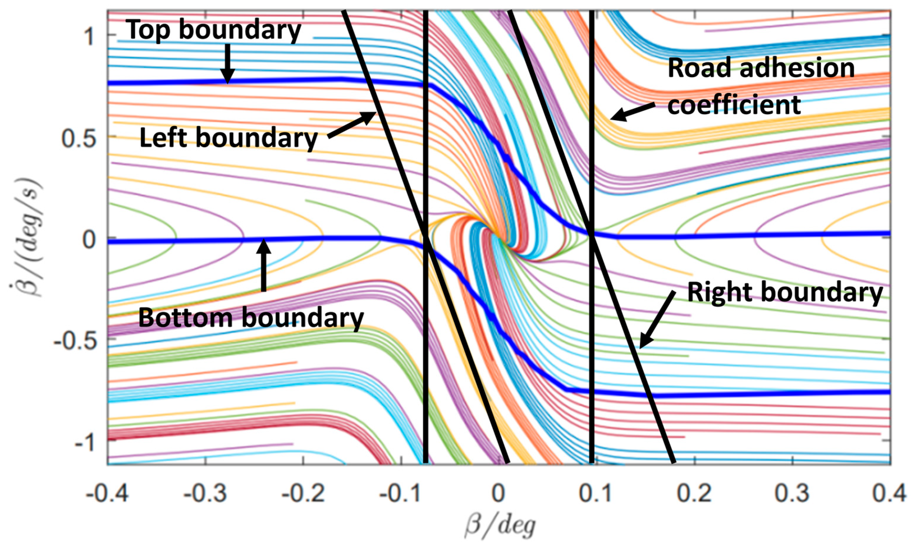
The β β ˙ phase–plane method defines stability boundaries as two symmetric straight lines around the origin O, typically expressed by Equation (49):
β + B 1 β ˙ B 2
For this study, stability boundaries are analyzed under the following conditions: vehicle speed vx = 72 km/h, steering wheel angle δf = 0°, and road adhesion coefficient μ = 0.8. The resulting β β ˙ phase plane and stability domain are shown in Figure 3. Within the stability domain, the phase trajectory of the sideslip angle (β) converges toward the origin, indicating the vehicle’s ability to autonomously correct its trajectory and maintain yaw dynamic equilibrium. Outside the stability domain, the phase trajectory diverges irreversibly, leading to deviations from equilibrium states and loss of stability.
The stability judgment mechanism operates as follows:
Stability Threshold Check: If the system exceeds predefined stability thresholds, actuators execute a dual-control strategy—performing trajectory tracking and reference yaw angle control to drive the system back into the stability domain.
Stable-State Control: If the system remains within the stability domain, single-objective control prioritizes precise tracking of the reference yaw angle.
Existing research highlights the significant influence of longitudinal speed (vx), road adhesion coefficient (μ), and steering wheel angle (δf) on phase–plane stability boundaries. For this study, δf = 0° is fixed, and the focus is on vx and μ.
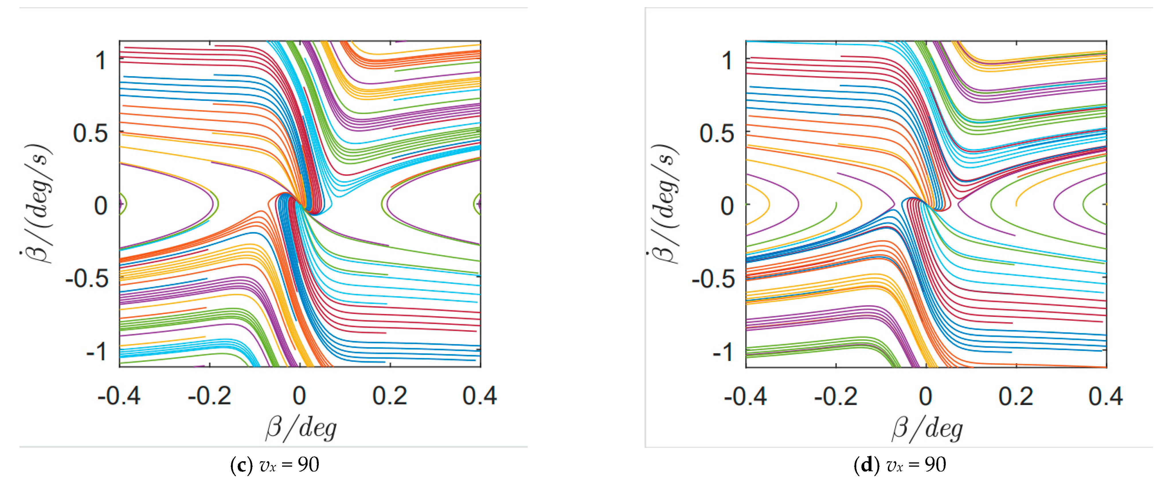
Simulations under a road adhesion coefficient of 0.75 at different speeds (30, 60, 90, and 120 km/h) reveal that higher speeds narrow the stability domain (Figure 4).
It can be seen that under the same road adhesion coefficient condition, the higher the speed of the vehicle, the narrower the boundary of the stability domain, and the smaller the side-bias angle and the side-bias angle angular velocity allowed by the stability criterion.
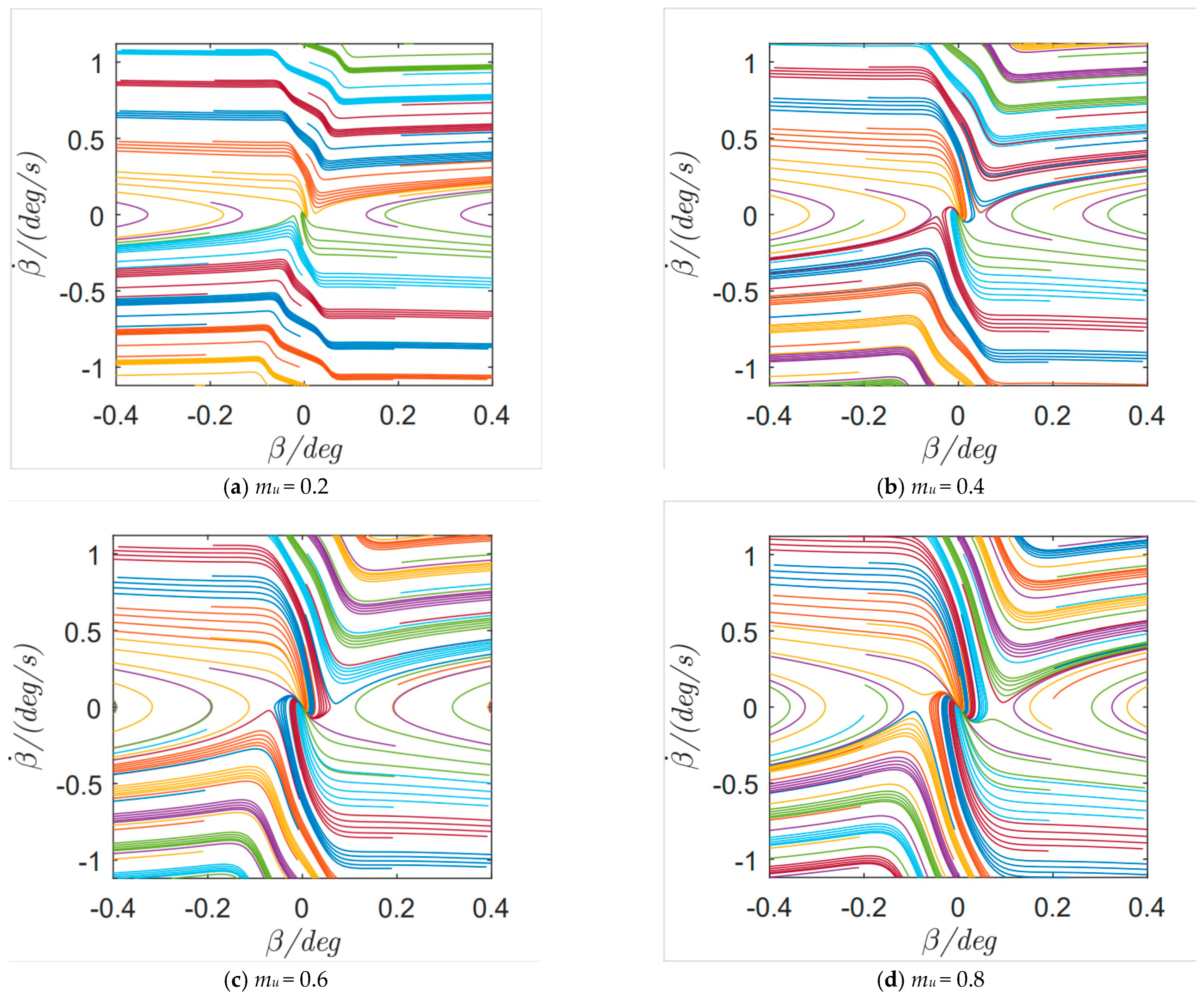
Similarly, at a fixed longitudinal speed, lower road adhesion coefficients reduce the stability domain (Figure 5).
It can be seen that when the longitudinal speed of the vehicle is the same, the lower the road adhesion coefficient, the smaller the stability domain. With the increase of the road adhesion coefficient, the stability domain becomes wider, and the critical value of the side offset angle of the center of mass that allows the vehicle to lose stability is also larger.
Stability boundaries for different adhesion coefficients are defined in Table 1.
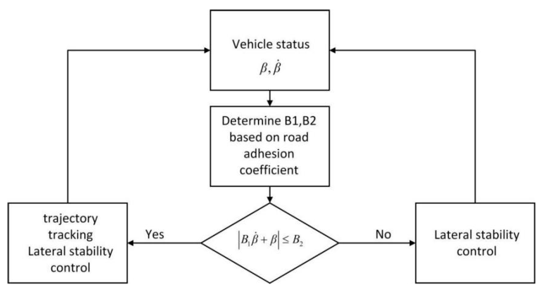
The decision framework (Figure 6) operates as follows:
If Equation (49) is violated, the system determines that the vehicle is in a state of instability, and it activates yaw stability control.
If stability criteria are met, trajectory tracking and yaw stability control are executed simultaneously.

4. Simulation and Results

To verify the effectiveness of the proposed trajectory-tracking disturbance rejection controller for ADDEVs under steer-by-wire failure conditions, a co-simulation platform integrating Carsim® and MATLAB/Simulink is established, and key vehicle parameters are listed in Table 1. Key vehicle parameters include vehicle mass (m), yaw moment of inertia (Iz), tire rolling radius (r), front and rear wheelbases (lf and lr), front and rear wheel cornering stiffnesses (Naf and Nar), gravitational acceleration (g), wheelbase (tw), motor moment of inertia (Jm), and motor damping coefficient (Bm). These parameters directly impact vehicle dynamics and, in turn, controller performance. These parameters are primarily derived from actual vehicle values. In simulations, we selected a standard speed of 72 km/h, typical for urban and highway driving. And we selected μ = 0.75 as a typical value for dry roads. We evaluated the controller’s adaptability under various operating conditions, and it demonstrates that the controller maintains good performance despite parameter changes.

4.1. Serpentine Maneuver

The simulation duration is set to 30 s, with a vehicle speed of 72 km/h and a road adhesion coefficient μ of 0.75. The control group used a traditional differential steering LQR controller for the upper layer and an average torque allocation strategy for the lower layer.
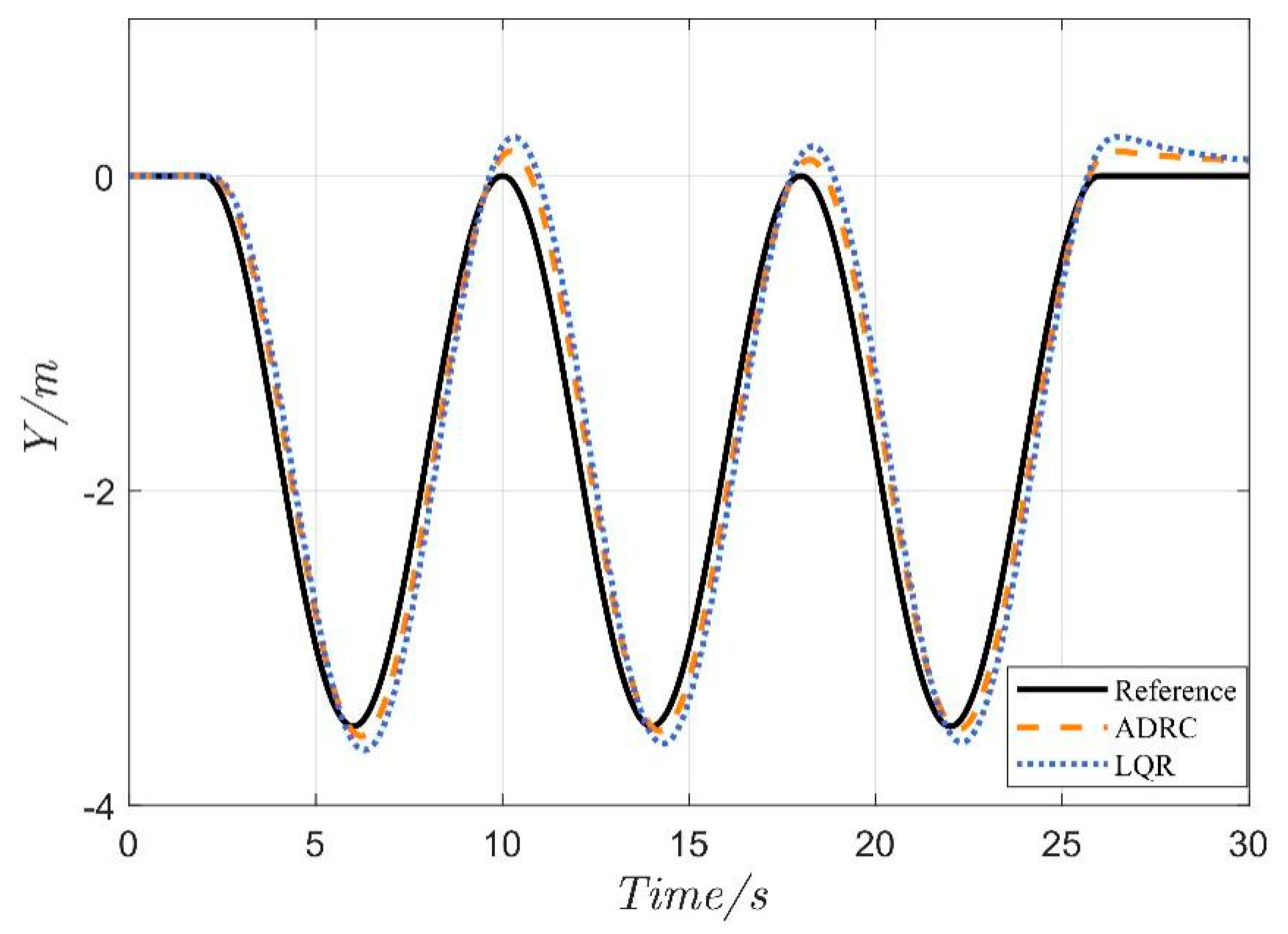
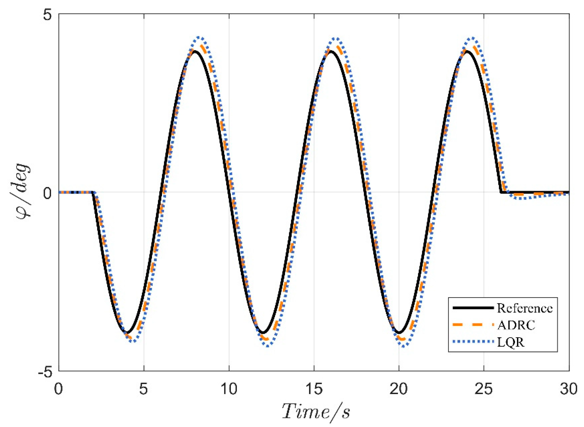
According to the comparative results in Figure 7 and Figure 8, both the proposed active disturbance rejection fault tolerant controller (ADRC) and the traditional LQR differential steering controller achieve trajectory-tracking control under steer-by-wire failure conditions. However, significant differences exist in dynamic response accuracy and tracking stability. Specifically, the ADRC controller exhibits smaller trajectory deviation and lower yaw angle error during reference path tracking. Notably, the ADRC controller maintains robust control performance even under partial failure of the steering actuator through real-time disturbance estimation and compensation.
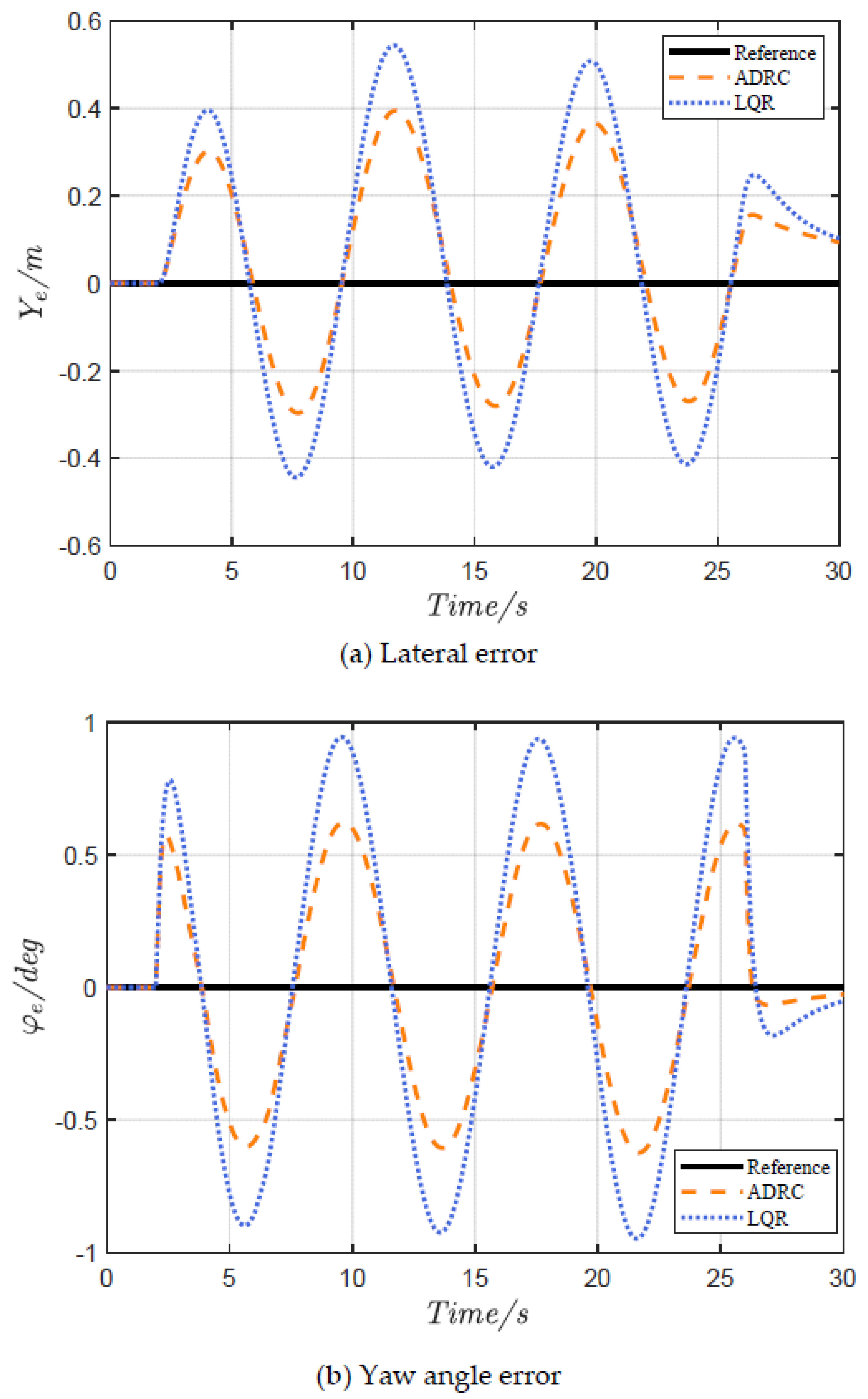
The lateral error comparison in Figure 9a and the yaw angle error comparison in Figure 9b reveal that the ADRC controller outperforms the LQR controller in both key metrics. The data shows that the maximum lateral tracking error of the ADRC controller is 0.4 m, 29.8% lower than the LQR controller’s 0.57 m. The maximum yaw angle tracking error of the ADRC controller is 0.59°, a 37.2% reduction compared to the LQR controller’s 0.94°.
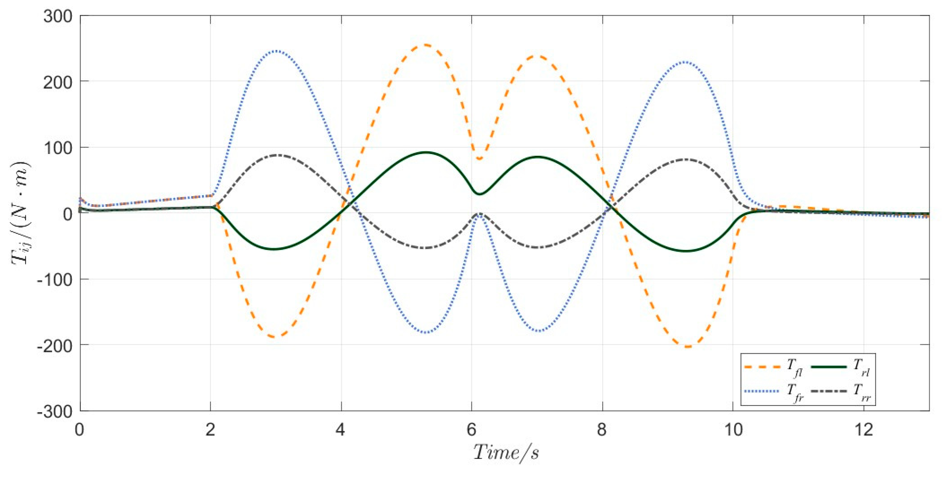
As shown in Figure 10, under steer-by-wire failure conditions, the vehicle achieves heading tracking control by dynamically adjusting the four-wheel driving torque distribution. This strategy utilizes differential driving forces on the front and rear axles to actively generate equivalent yaw moments by compensating for the loss of steering functionality.
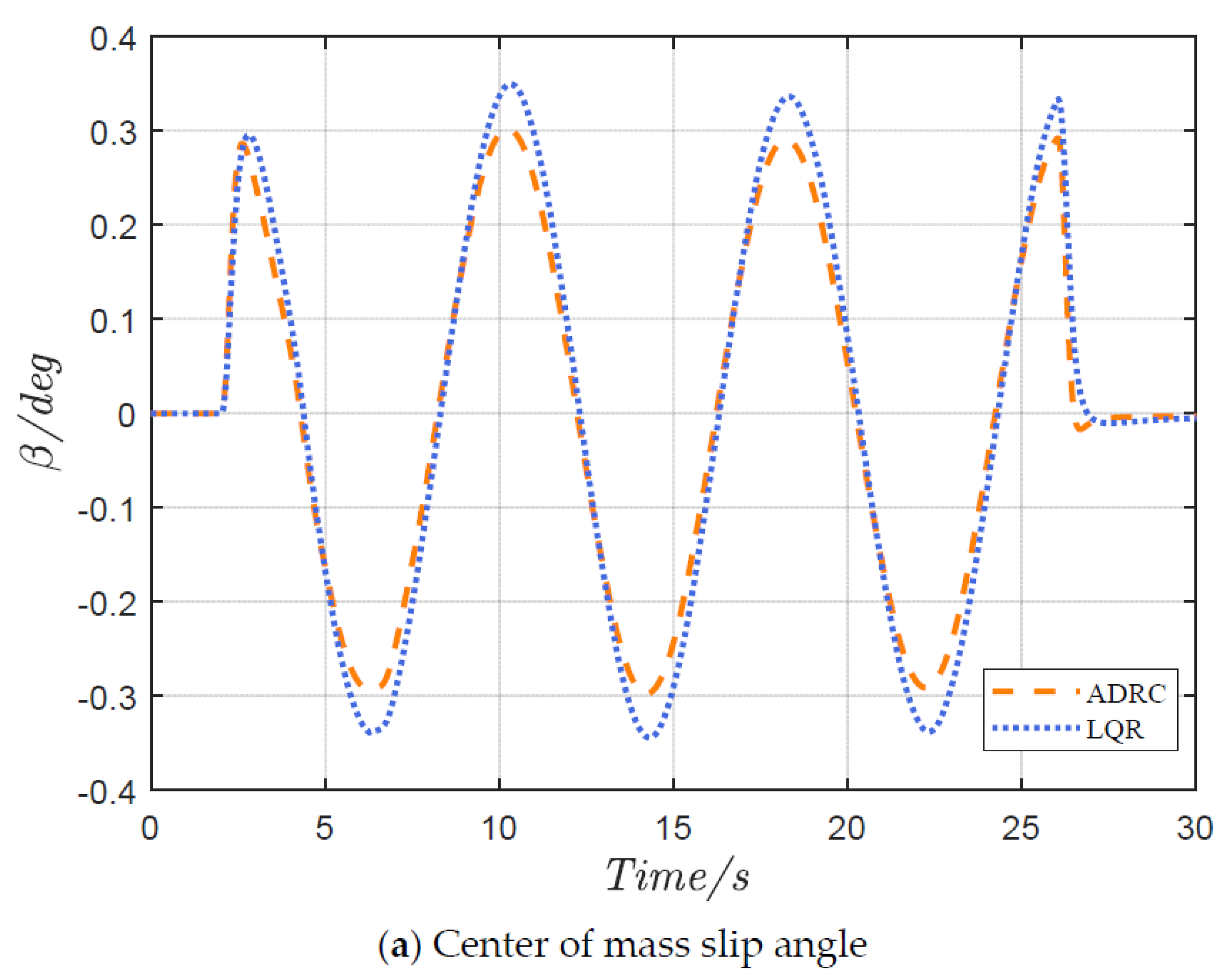
The lateral stability comparison in Figure 11 demonstrates the superior performance of the ADRC controller. The peak sideslip angle of the ADRC controller is 0.29°, 12.1% lower than the LQR controller’s 0.33° (Figure 11a). The β β ˙ phase–plane analysis in Figure 12b indicates that the ADRC control trajectory exhibits better convergence characteristics within 95% of the time interval. The nonlinear extended state observer-based disturbance compensation mechanism ensures stable phase trajectory characteristics under strong coupling conditions.
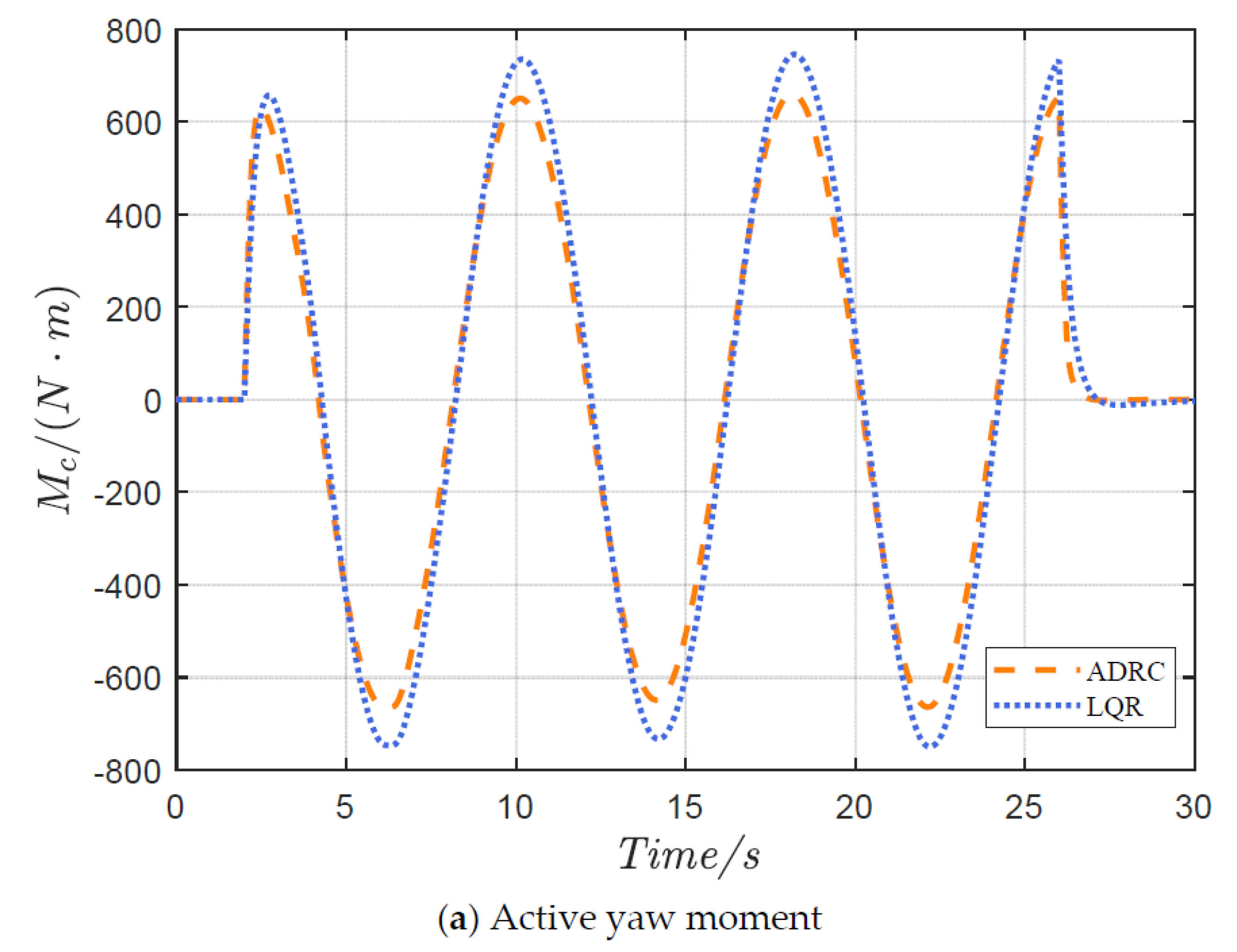
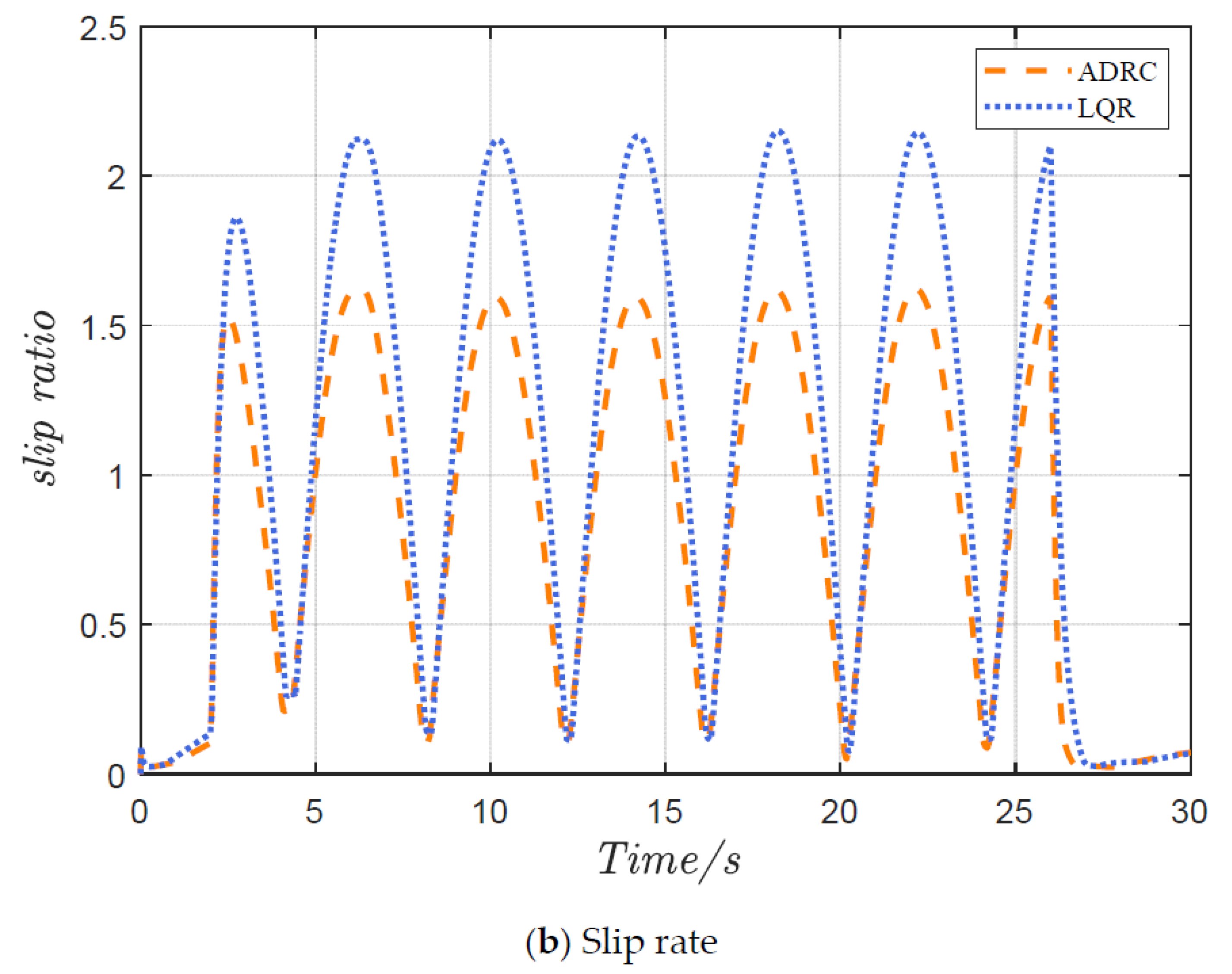
From the yaw moment output curves in Figure 12a, the ADRC controller demonstrates better yaw moment decision-making capability. Meanwhile, the tire slip ratio comparison in Figure 12b shows that the peak tire slip ratio of the ADRC controller (1.61%) is 26.5% lower than that of the LQR controller (2.19%). This validates that the proposed torque allocation strategy optimizes tire force utilization, effectively mitigating the impact of tire nonlinearity on vehicle stability.
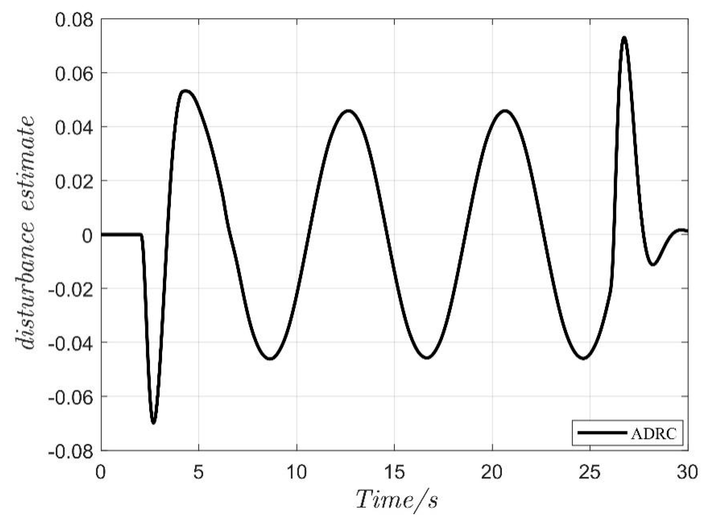
Figure 13 illustrates the disturbance estimation and compensation results of the extended state observer. It confirms that the ADRC controller achieves comprehensive optimization of tracking accuracy, lateral stability, and tire utilization through coordinated disturbance estimation and dynamic torque allocation.

4.2. Double-Lane Change Maneuver

The simulation duration is set to 12 s, with a vehicle speed of 72 km/h and a road adhesion coefficient μ of 0.75. The control group used the same traditional LQR controller for comparison.
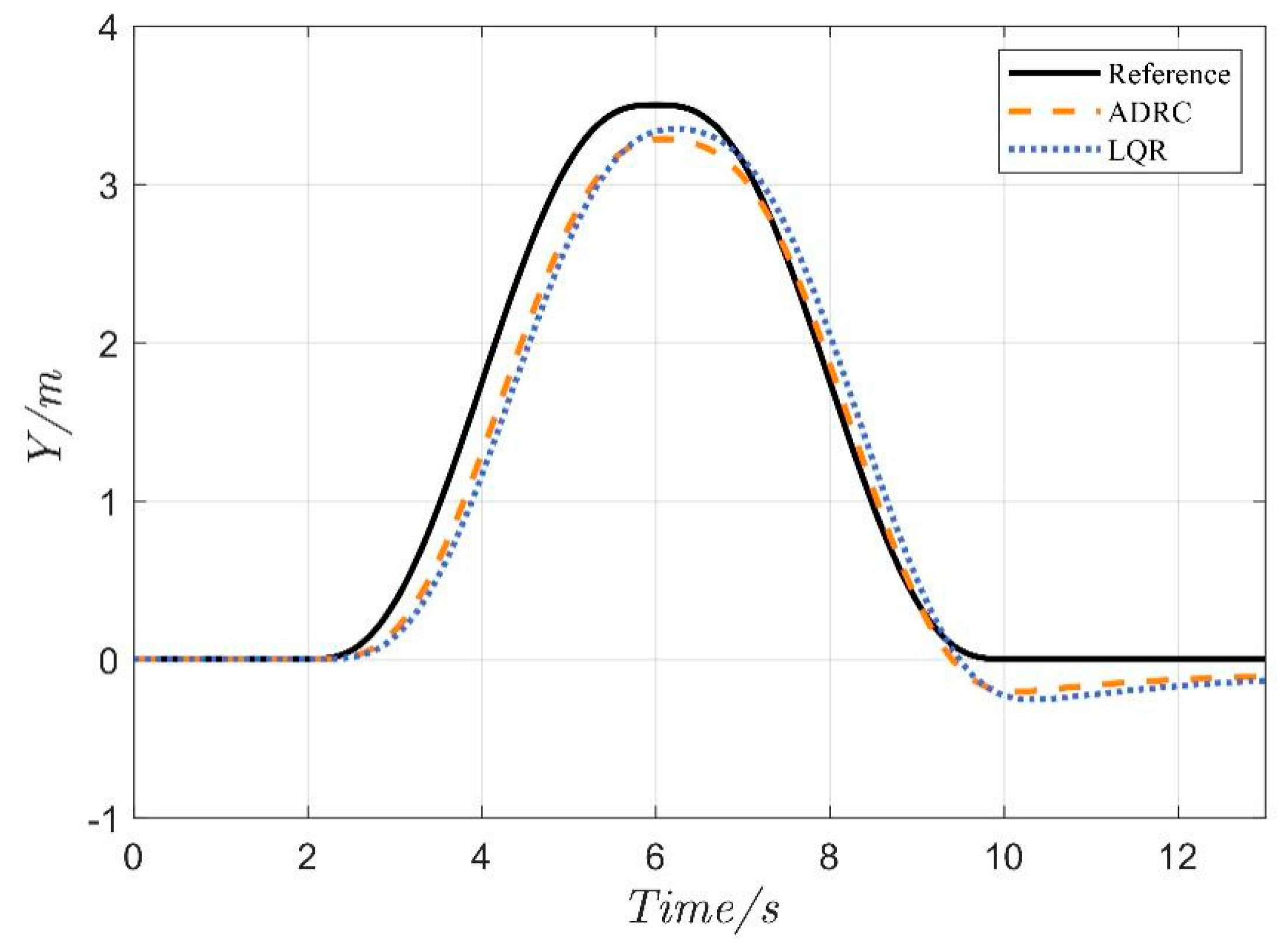
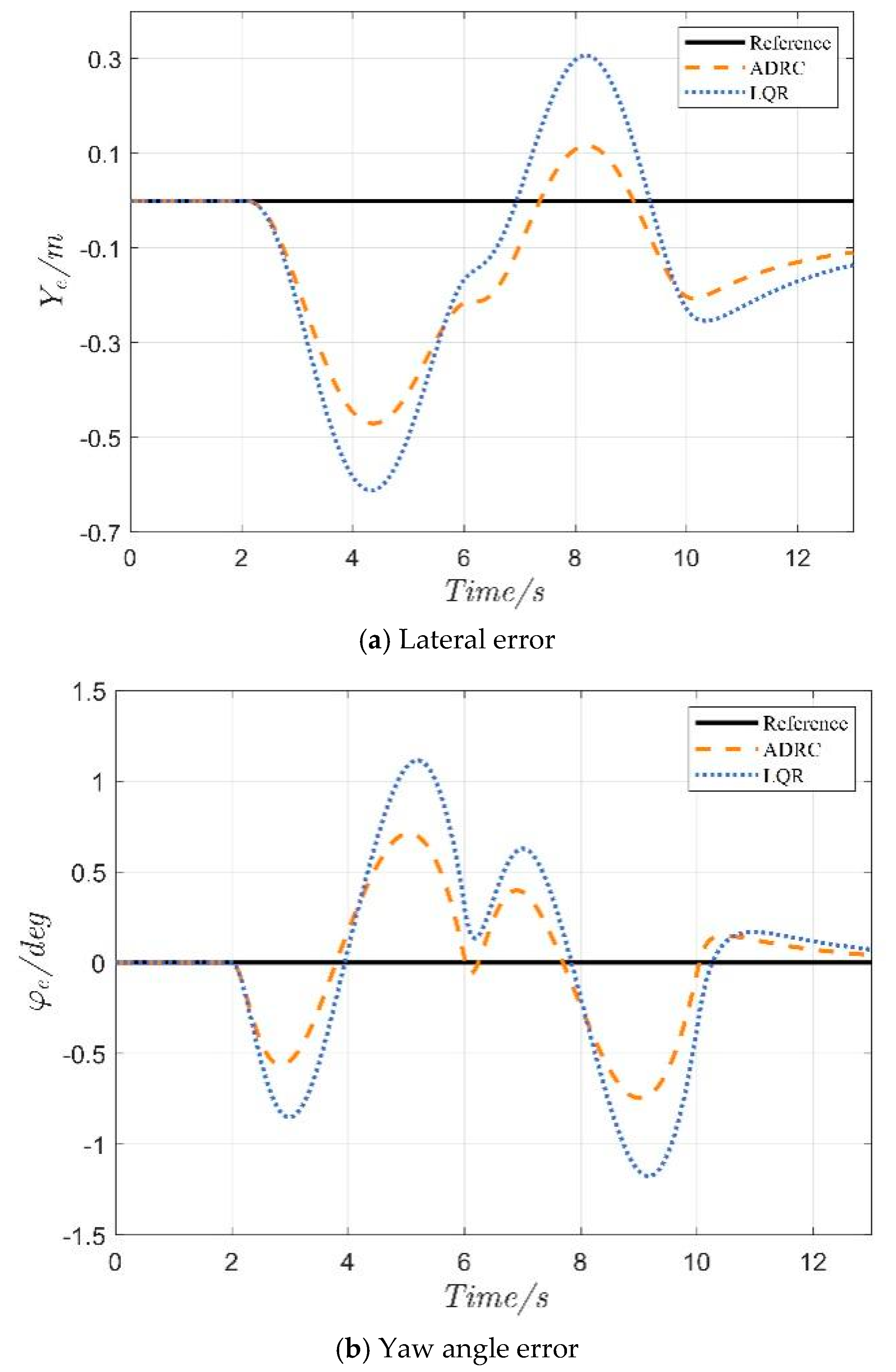
As shown in Figure 14 and Figure 15, the ADRC controller exhibits smaller trajectory deviation and yaw angle error in the double-lane change scenario. Even under complete steering actuator failure, the ADRC controller maintains robust performance through real-time disturbance compensation.
The lateral error and yaw angle error comparisons in Figure 16 highlight the ADRC controller’s advantages. The maximum lateral tracking error of the ADRC controller is 0.391 m, 36.1% lower than the LQR controller’s 0.612 m. The maximum yaw angle error is 0.74°, a 39.8% reduction compared to the LQR controller’s 1.23°.
Figure 17 demonstrates the vehicle’s heading tracking capability through dynamic four-wheel torque allocation.
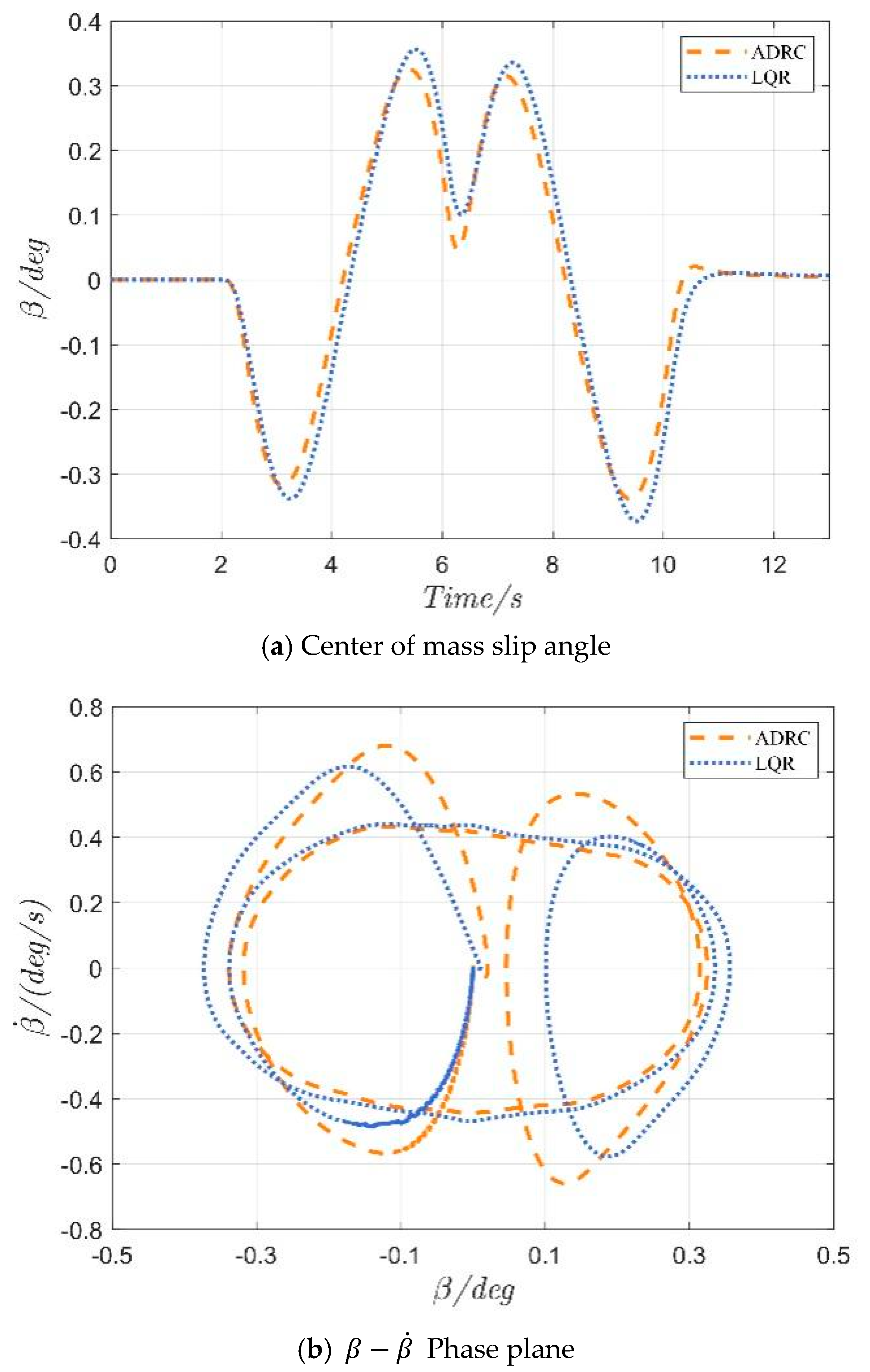
The sideslip angle comparison in Figure 18a shows that the ADRC controller reduces the peak sideslip angle by 11.1% (0.32° vs. 0.36°). The β β ˙ phase–plane analysis in Figure 18b confirms that the ADRC controller maintains phase trajectories closer to the stable equilibrium point.
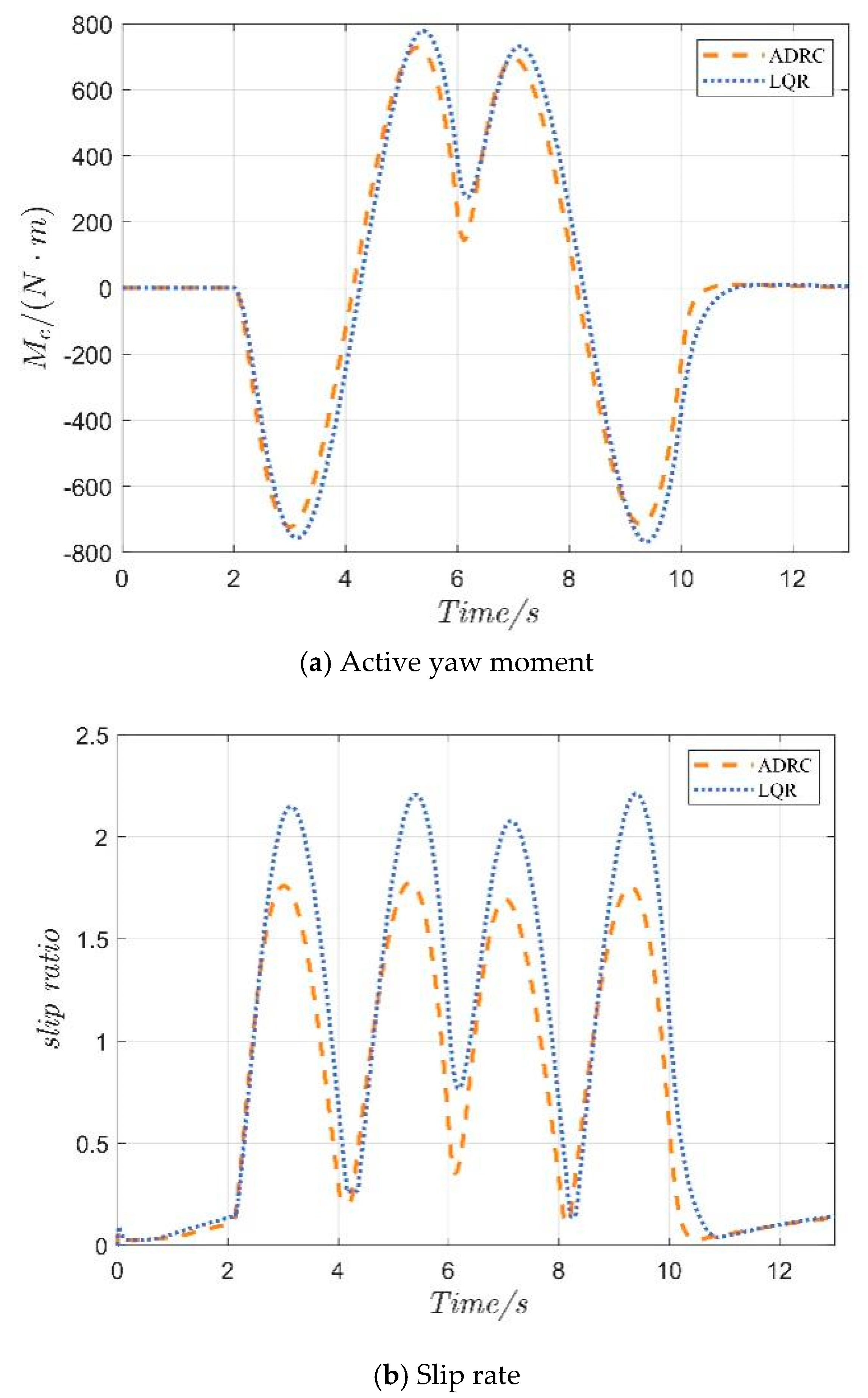
From Figure 19, the ADRC controller achieves a peak tire slip ratio of 1.69%, 24.2% lower than the LQR controller (2.23%). This further validates the effectiveness of the tire force saturation constraint algorithm.
Figure 20 illustrates the excellent real-time disturbance estimation capability of the extended state observer. The ADRC controller achieves multi-objective optimization in tracking accuracy, stability, and tire utilization through coordinated disturbance compensation and torque allocation. Although the proposed method has been validated on a joint simulation platform, future work will address current limitations through two critical phases: (1) hardware-in-the-loop (HIL) validation using automotive-grade ECUs to evaluate real-time performance under stochastic disturbances, and (2) physical deployment with experimental vehicle testbeds or scaled robotic prototypes incorporating real-world sensor data to improve and evaluate its generalization ability and stability in unknown driving situations or environmental factors.
Table 2 also summarizes key performance metrics (MAE, RMSE, and MSE) for both controllers in two test scenarios. The ADRC controller shows significant improvements in all metrics compared to the LQR controller, with performance advancements (PA) ranging from 9.24% to 58.96%. Quantitative results in Table 2 demonstrate the superior performance of the proposed ADRC+KKT controller over the LQR and average allocation baseline across all metrics and scenarios. The ADRC framework reduced lateral tracking error by 29.42% (MAE) and 50.15% (MSE) in serpentine maneuvers, indicating exceptional outlier rejection during aggressive steering. In double-lane-change tests, it achieved a 36.03% MAE and 58.96% MSE reduction in yaw angle error, highlighting its robust disturbance compensation under transient conditions. While stability metric improvements were more moderate (9.24–13.06% MAE reduction), the 12.76% RMSE decrease confirms reduced sideslip oscillations, consistent with phase trajectory convergence. These advancements stem from two synergistic mechanisms: (1) ESO’s real-time compensation of nonlinear disturbances overcoming LQR’s fixed-gain limitations, and (2) KKT’s explicit stability constraints derived from phase–plane boundaries eliminating the stability-blind allocation in baseline methods.

5. Conclusions

This study proposes a hierarchical fault tolerant control framework for ADDEVs when steer-by-wire (SBW) systems fail. By combining cascade active disturbance rejection control (ADRC) with torque allocation based on Karush–Kuhn–Tucker (KKT), it effectively solves the problems of trajectory tracking degradation and lateral instability in automated vehicles. The upper-layer ADRC employs an extended state observer (ESO) to dynamically estimate and compensate for nonlinear disturbances, including tire force variations and actuator faults, while the lower-layer optimizes four-wheel torque distribution under tire saturation constraints using KKT conditions. A 3-DOF differential steering dynamics model is established to characterize electromechanical coupling effects, complemented by a phase–plane stability criterion with adaptive thresholds for road adhesion and speed. Co-simulations (CarSim/Simulink) demonstrate superior performance over traditional LQR methods: 36.1% reduction in lateral tracking error, 39.8% lower yaw deviation, and 24.2% decreased tire slip ratio, while maintaining real-time computation compliant. The proposed strategy ensures robust trajectory tracking and stability under severe SBW failures, which is helpful for offering a scalable solution of L4 autonomous driving systems with implications for V2X-integrated fault management architectures. However, the strategy may present limitations. Its performance is sensitive to the fidelity of the underlying 3-DOF vehicle model, particularly under very high speeds or extreme tire-road adhesion variations. Parameter tuning requirements for both the ADRC controllers and the adaptive stability criterion also warrant consideration for practical deployment. Future work should explore model adaptation and enhanced online parameter robustness. Importantly, the core “upper-layer disturbance compensation (ADRC) and lower-layer optimized force allocation (KKT)” hierarchical framework demonstrates significant potential for managing other critical actuator failures, such as brake-by-wire (BBW) system faults. Optimizing longitudinal/brake force distribution using KKT under tire saturation constraints would address BBW failures similarly, leveraging differential drive/brake torque to compensate for lost braking capability and maintain stability.

Author Contributions

Conceptualization, X.J., H.L., Y.T., J.L. (Jianning Lu), J.L. (Jianbo Lv) and N.V.O.I.; supervision, X.J.; conception and design, X.J. and H.L.; collection and assembly of data, X.J., H.L., Y.T., J.L. (Jianning Lu), J.L. (Jianbo Lv) and N.V.O.I.; manuscript writing, X.J., H.L., Y.T., J.L. (Jianning Lu), J.L. (Jianbo Lv) and N.V.O.I.; funding, X.J. All authors have read and agreed to the published version of the manuscript.

Funding

Natural Science Foundation of Shanghai (25ZR1401118), and the Key Research and Development Program of China Yangtze River Delta (Grant No. 2023CSJGG0900).

Data Availability Statement

Data are contained within the article.

Conflicts of Interest

The authors declare no conflicts of interest.

References

  1. Deng, H.; Zhao, Y.; Nguyen, A.T.; Huang, C. Fault tolerant predictive control with deep-reinforcement-learning-based torque distribution for four in-wheel motor drive. IEEE/ASME Trans. Mechatron. 2023, 28, 668–680. [Google Scholar] [CrossRef]
  2. Yassine, A.; Hossain, M.S.; Muhammad, G.; Guizani, M. Double auction mechanisms for dynamic autonomous electric vehicles energy trading. IEEE Trans. Veh. Technol. 2019, 68, 7466–7476. [Google Scholar] [CrossRef]
  3. Liu, C.; Liu, H.; Han, L.; Wang, W.; Guo, C. Multi-Level Coordinated Yaw Stability Control Based on Sliding Mode Predictive Control for Distributed Drive Electric Vehicles Under Extreme Conditions. IEEE Trans. Veh. Technol. 2023, 72, 280–296. [Google Scholar] [CrossRef]
  4. Wang, F.; Shen, T.; Zhao, M.; Ren, Y.; Lu, Y.; Feng, B. Lane-Change Trajectory Planning and Control Based on Stability Region for Distributed Drive Electric Vehicle. IEEE Trans. Veh. Technol. 2024, 73, 504–521. [Google Scholar] [CrossRef]
  5. Barari, A.; Saraygord Afshari, S.; Liang, X. Coordinated control for path-following of an autonomous four in-wheel motor drive electric vehicle. Proc. Inst. Mech. Eng. C J. Mech. Eng. 2022, 236, 6335–6346. [Google Scholar] [CrossRef]
  6. Gözü, M.; Ozkan, B.; Emirler, M.T. Disturbance observer based active independent front steering control for improving vehicle yaw stability and tire utilization. Int. J. Autom. Technol. 2022, 23, 841–854. [Google Scholar] [CrossRef]
  7. Fekih, A.; Seelem, S.R. A fault tolerant control design for automatic steering control of ground vehicles. In Proceedings of the 2012 IEEE International Conference on Control Applications, Dubrovnik, Croatia, 3–5 October 2012; pp. 1491–1496. [Google Scholar]
  8. Huang, C.; Naghdy, F.; Du, H. Delta Operator-Based Fault Estimation and Fault Tolerant Model Predictive Control for Steer-By-Wire Systems. IEEE Trans. Control Syst. Technol. 2018, 26, 1810–1817. [Google Scholar] [CrossRef]
  9. Huang, C.; Naghdy, F.; Du, H. Observer-Based Fault Tolerant Controller for Uncertain Steer-by-Wire Systems Using the Delta Operator. IEEE/ASME Trans. Mechatron. 2018, 23, 2587–2598. [Google Scholar] [CrossRef]
  10. Sajjan, A.; Pathak, R.R.; Mathad, S.; Kalligudd, S. Stability Control Using Adaptive Integral SMC Applicable to Variable Speed EV. In Proceedings of the 2024 International Conference on Innovation and Novelty in Engineering and Technology (INNOVA), Vijayapura, India, 20–21 December 2024; pp. 1–6. [Google Scholar]
  11. Jin, X.; Lv, H.; He, Z.; Li, Z.; Wang, Z.; Ikiela, N.V.O. Design of Active Disturbance Rejection Controller for Trajectory-Following of Autonomous Ground Electric Vehicles. Symmetry 2023, 15, 1786. [Google Scholar] [CrossRef]
  12. Chen, H.; Tu, Y.; Wang, H.; Shi, K.; He, S. Fault tolerant tracking control based on reinforcement learning with application to a steer-by-wire system. J. Frankl. Inst. 2022, 359, 1152–1171. [Google Scholar] [CrossRef]
  13. He, S.; Xu, X.; Xie, J.; Wang, F.; Liu, Z.; Zhao, F. Fault detection and fault tolerant control of autonomous steering system for intelligent vehicles combining Bi-LSTM and SPRT. Measurement 2023, 212, 112708. [Google Scholar] [CrossRef]
  14. Zhao, X.; Zhao, L. Steering angle tracking control of steer-by-wire system with prescribed performance under primary sensor failure. Control Eng. Pract. 2025, 161, 106354. [Google Scholar] [CrossRef]
  15. Wang, X.; Pan, L.; Tian, Y.; Liu, Y.; Li, L. Adaptive fault tolerant fixed-time sliding mode tracking control for steer-by-wire system with dual-three-phase PMSM. IEEE Trans. Veh. Technol. 2025, 161, 106354. [Google Scholar] [CrossRef]
  16. Shi, G.; Guo, C.; Wang, S.; Liu, T. Angle tracking and fault tolerant control of steer by-wire system with dual three-phase motor for autonomous vehicle. IEEE Trans. Intell. Transp. Syst. 2024, 25, 5842–5853. [Google Scholar] [CrossRef]
  17. Jin, X.; Wang, Q.; Yan, Z.; Yang, H.; Yin, G. Integrated robust control of path following and lateral stability for autonomous in-wheel-motor-driven electric vehicles. Proc. Inst. Mech. Eng. D J. Autom. Eng. 2025, 239, 12696–12706. [Google Scholar] [CrossRef]
  18. Khadraoui, S.; Fareh, R.; Baziyad, M.; Bakr Elbeltagy, M.; Bettayeb, M. A Comprehensive Review and Applications of Active Disturbance Rejection Control for Unmanned Aerial Vehicles. IEEE Access 2024, 12, 185851–185868. [Google Scholar] [CrossRef]
  19. Lv, H.; Wang, X.; Xie, B.; Shi, B.; Li, Q.; Xu, Y. A Hierarchical Cooperative Control Strategy for In Situ Steering of Distributed Drive Electric Vehicle. IEEE Trans. Transp. Electrif. 2025, 11, 8427–8438. [Google Scholar] [CrossRef]
  20. Shi, X.; Wang, H.; Chen, L.; Sun, X.; Yang, C.; Cai, Y. Robust Path Tracking Control of Distributed Driving Six-Wheel Steering Commercial Vehicle Based on Coupled Active Disturbance Rejection. IEEE Trans. Veh. Technol. 2023, 72, 13940–13952. [Google Scholar] [CrossRef]
  21. Tian, Y.; Ma, H.; Ma, L.; Li, S.; Wang, Z.; Wang, X. Path Tracking Control of Commercial Vehicle Emergency Obstacle Avoidance Based on MPC and Active Disturbance Rejection Control. IEEE Trans. Transp. Electrif. 2025, 11, 7162–7170. [Google Scholar] [CrossRef]
  22. Zou, S.; Zhao, W.; Wang, C.; Liang, W.; Chen, F. Tracking and Synchronization Control Strategy of Vehicle Dual-Motor Steer-by-Wire System via Active Disturbance Rejection Control. IEEE/ASME Trans. Mechatron. 2023, 28, 92–103. [Google Scholar] [CrossRef]
  23. Cao, Y.; Yang, W.; Wang, S.; He, S.; Liu, Z.; Xie, L. Improved Trajectory Tracking Control for a Continuum Robot Using Error-Driven ADRC With Input Mapping Method. IEEE Trans. Ind. Electron. 2024, 71, 12696–12706. [Google Scholar] [CrossRef]
  24. Zhang, J.; Cui, C.; Gu, S.; Wang, T.; Zhao, L. Trajectory Tracking Control of Pneumatic Servo System: A Variable Gain ADRC Approach. IEEE Trans. Cybern. 2023, 53, 6977–6986. [Google Scholar] [CrossRef]
  25. Wu, J.; Zhang, J.; Nie, B.; Liu, Y.; He, X. Adaptive control of PMSM servo system for Steering-by-Wire system with disturbances observation. IEEE Trans. Transport. Electrif. 2022, 8, 2015–2028. [Google Scholar] [CrossRef]
  26. Han, Z.; Xu, N.; Chen, H.; Huang, Y.; Zhao, B. Energy-efficient control of electric vehicles based on linear quadratic regulator and phase plane analysis. Appl. Energy 2018, 213, 639–657. [Google Scholar] [CrossRef]
  27. Qin, L.; Hu, J.; Li, H.; Chen, W. Fuzzy logic controllers for specialty vehicles using a combination of phase plane analysis and variable universe approach. IEEE Access 2017, 5, 1579–1588. [Google Scholar] [CrossRef]
  28. Yu, Z.; Hou, Y.; Leng, B.; Xiong, L.; Li, Y. Disturbance compensation and torque coordinated control of four In-Wheel motor Independent-Drive electric vehicles. IEEE Access 2020, 8, 119758–119767. [Google Scholar] [CrossRef]
  29. Seiffer, A.; Frey, M.; Gauterin, F. Control allocation approach using differential steering to compensate for steering actuator failure. IEEE Open J. Intell. Transp. Syst. 2024, 5, 756–773. [Google Scholar] [CrossRef]
  30. Wang, R.; Yu, X.; Sun, Q.; Li, D.; Gui, Y.; Wang, P. The Integrated Reference Region Analysis for Parallel DFIGs’ Interfacing Inductors. IEEE Trans. Power Electron. 2024, 39, 7632–7642. [Google Scholar] [CrossRef]
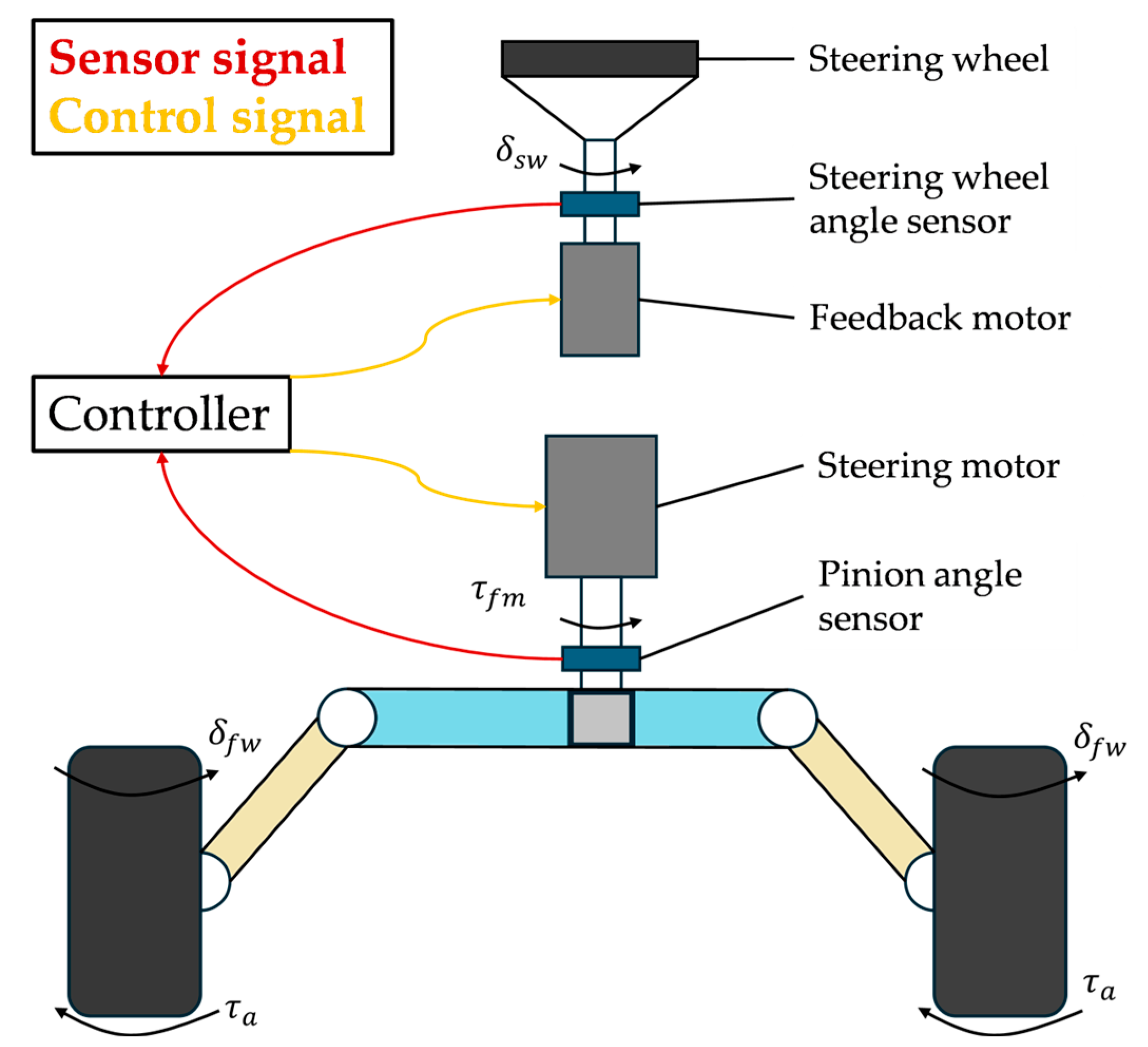
Figure 1. The schematic diagram of the steer-by-wire (SBW) system.
Symmetry 17 01471 g001
Figure 2. Fault tolerant control strategy architecture for ADDEVs under SBW system failure.
Symmetry 17 01471 g002
Figure 3. Stability domain partition.
Symmetry 17 01471 g003
Figure 4. Effect of different high road adhesion coefficients on the phase plane.
Symmetry 17 01471 g004aSymmetry 17 01471 g004b
Figure 5. Effect of different low road adhesion coefficients on the phase plane.
Symmetry 17 01471 g005
Figure 6. Vehicle instability judgment structure diagram.
Symmetry 17 01471 g006
Figure 7. Tracking trajectory under serpentine maneuver.
Symmetry 17 01471 g007
Figure 8. Yaw angle under serpentine maneuver.
Symmetry 17 01471 g008
Figure 9. Trajectory tracking error under serpentine maneuver.
Symmetry 17 01471 g009
Figure 10. Torque distribution under serpentine maneuver.
Symmetry 17 01471 g010
Figure 11. Comparison of the center of mass side slip angle under serpentine maneuver.
Symmetry 17 01471 g011aSymmetry 17 01471 g011b
Figure 12. Active yaw moment and tire slip under serpentine maneuver.
Symmetry 17 01471 g012aSymmetry 17 01471 g012b
Figure 13. Yaw angle disturbance estimation under serpentine maneuver.
Symmetry 17 01471 g013
Figure 14. Tracking trajectory under a double-lane change maneuver.
Symmetry 17 01471 g014
Figure 15. Yaw angle under a double-lane change maneuver.
Symmetry 17 01471 g015
Figure 16. Trajectory tracking error under a double-lane change maneuver.
Symmetry 17 01471 g016
Figure 17. Torque distribution diagram under a double-lane change maneuver.
Symmetry 17 01471 g017
Figure 18. Comparison of the center of mass side slip angle under a double-lane change maneuver.
Symmetry 17 01471 g018
Figure 19. Active yaw moment and tire slip under a double-lane change maneuver.
Symmetry 17 01471 g019
Figure 20. Yaw angle disturbance estimation under double-lane change maneuver.
Symmetry 17 01471 g020
Table 1. Vehicle key parameters table.
ParameterNumericUnitParameterNumericUnit
vx72Km/hu0.75-
m1270KgIz1537kg·m2
r0.325mlf1.015m
Naf130,034N/radNar70,038N/rad
g9.81M/s2tw1.605m
Jm0.002129Kg·m2Bm0.038N·s/rad
Table 2. Error index of the controller under various parameters.
Serpentine ManeuverDouble-Lane Change Maneuver
ParameterIndexADRCLQRPA1ADRCLQRPA1
MAE0.1770.25129.42%0.1560.20322.84%
ye(m)RMSE0.2080.29529.39%0.2070.26521.95%
MSE0.0430.08750.15%0.0430.07039.09%
MAE0.3200.48834.44%0.2620.40936.03%
φe(deg)RMSE0.3900.58833.77%0.3560.55635.94%
MSE0.1520.34656.14%0.1270.30958.96%
MAE0.1500.17313.06%0.1290.1429.24%
β(deg)RMSE0.1850.21212.76%0.1790.1958.21%
MSE0.0340.04523.89%0.0320.03815.75%
Disclaimer/Publisher’s Note: The statements, opinions and data contained in all publications are solely those of the individual author(s) and contributor(s) and not of MDPI and/or the editor(s). MDPI and/or the editor(s) disclaim responsibility for any injury to people or property resulting from any ideas, methods, instructions or products referred to in the content.