Article

Characteristic Model-Based Discrete Adaptive Integral SMC for Robotic Joint Drive on Dual-Core ARM

School of Electrical Engineering, Nanjing Vocational University of Industry Technology, Nanjing 210023, China
Symmetry 2025, 17(9), 1436; https://doi.org/10.3390/sym17091436
Submission received: 20 June 2025 / Revised: 6 August 2025 / Accepted: 22 August 2025 / Published: 3 September 2025
(This article belongs to the Section Engineering and Materials)

Abstract

Addressing escalating demands for high-precision compact robotic actuators, this study overcomes persistent challenges from nonlinear transmission dynamics and computational constraints through a co-designed framework integrating three innovations. A real-time second-order characteristic modeling approach enables 10 kHz online parameter identification, reducing computational load by 13.1% versus MPC. Building on this foundation, a hybrid integral sliding-mode controller eliminating modeling errors while maintaining ≤0.25 rad/s tracking error (SRMSE) under variable loads was created. These algorithmic advances are embedded within a miniaturized dual-ARM platform (47 × 47 × 12 mm3) achieving <30-ns overcurrent protection and 36% cost reduction versus DSP/FPGA solutions. Validated via Lyapunov stability proofs and experiments, this framework is particularly effective for high-performance robotic joint control in spatially- and thermally-constrained environments while dynamically compensating for unmodeled nonlinearities.

1. Introduction

The rapid advancement of artificial intelligence (AI) technologies has significantly accelerated the deployment of robotic systems as human surrogates for strenuous tasks across multiple industries [1,2,3]. Achieving agile and coordinated robotic maneuvers critically relies on high-performance joint actuators, where control precision fundamentally governs the robot’s holistic motion capabilities. As robotic applications proliferate exponentially, the demand for advanced joint actuators with high dynamic response and optimized size has escalated.
The operational requirements of joint actuators demand their control and drive systems with high power density [4,5,6], excellent dynamic response [7,8,9], robust load adaptability [10,11,12], and exceptional overload tolerance [13,14]. Robotic arms executing repetitive reciprocating motions necessitate accurate command tracking to ensure dynamic performance. Additionally, wide fluctuations in load torque and rotational inertia during cyclic operations require adaptive control compensation for maintaining precision. Recent studies address these challenges through diverse control strategies: A Lyapunov-based robust control method for permanent magnet synchronous motors (PMSMs) was proposed in [15], improving dynamic regulation under load disturbances and parameter variations. A data-driven friction compensation framework was developed in [16], incorporating an extended Kalman filter to suppress stochastic disturbances and enhance servo accuracy. Command filter techniques combined with a disturbance observer and adaptive backstepping control for trajectory tracking optimization was introduced in research [17]. Sliding mode control provides robust disturbance rejection for dynamic systems. Reference [18] developed an adaptive integral sliding mode controller for vehicle steer-by-wire systems, enhancing stability and NVH performance through real-time uncertainty compensation. Reference [19] proposed an adaptive backstepping sliding mode control scheme integrated with magneto-rheological dampers to suppress vibrations in earthquake-affected high-rise structures. Reference [20] introduced a continuous-time adaptive SMC method that eliminates a priori uncertainty-bound requirements. Specifically, continuous-time SMC necessitates infinitesimal sampling intervals to accurately compute derivatives—a condition incompatible with resource-constrained platforms such as ARM Cortex-M4 microcontrollers operating at practical sampling rates (e.g., 10 kHz). This fundamental constraint necessitates discrete control formulations for real-world embedded applications. In this context, reference [21] developed a discrete-time adaptive SMC framework demonstrating superior embedded system compatibility. Further advancing this approach, reference [22] designed an adaptive higher-order discrete SMC variant that effectively attenuates chattering while maintaining robustness.
Despite their prevalence, conventional control approaches exhibit critical limitations that impede their applicability in compact robotic systems. These methods fundamentally rely on pre-established system models demanding precise parameter identification and substantial computational resources, typically necessitating DSP or FPGA implementations [23,24,25,26,27]. These implementations confront insurmountable barriers in joint motor applications due to a triad of constraints: stringent real-time requirements mandate full control execution within 100μs at 10 kHz PWM frequencies, thermal limitations prohibit high-power computing in heatsink-restricted compact drives, and variable loading conditions demand adaptive algorithms exceeding the computational capabilities of ARM Cortex-M platforms [28]. This triad of challenges—computational intensity, thermal constraints, and dynamic adaptability—creates a critical research gap motivating our investigation into lightweight control architectures.
To address the fundamental contradiction above, we propose a characteristic model [29,30,31,32]-based adaptive control methodology that achieves optimal balance between computational efficiency and control precision. The term adaptive refers exclusively to the online identification of the characteristic model’s time-varying coefficients. This approach maps complex system dynamics and disturbance effects into time-varying parameters of reduced-order difference equations through real-time identification, enabling effective disturbance rejection with less computational overhead. The principal contributions of this research are listed as follows:
  • Real-Time Second-Order Characteristic Modeling
The proposed characteristic modeling-based control approach compresses high-order system dynamics in the joint motor into a computationally tractable second-order representation, enabling real-time online coefficient identification at 10 kHz even on resource-constrained microcontrollers.
2.
Hybrid Sliding-Mode Control Architecture
By integrating discrete-time adaptive integral sliding mode control (DAISMC) with characteristic modeling, the proposed architecture eliminates the need for precise modeling while effectively suppressing system uncertainties. This hybrid approach maintains exceptional control consistency, limiting speed regulation SRMSE degradation to 0.01 rad/s even under variable loading conditions. Besides, this approach achieves 13.1% faster controller execution compared to model predictive control (MPC).
3.
Co-Designed Miniaturized Drive Module
This work introduces a co-designed dual-ARM embedded drive module (47 × 47 × 12 mm3) featuring sub-30-nanosecond overcurrent protection, which achieves a 36% reduction in bill-of-materials (BOM) cost compared to conventional DSP or FPGA-based solutions.
The paper is structured as Figure 1: Section 2 develops a comprehensive mathematical model of the robotic joint motor system with friction, unmodeled dynamic and time-varying load. Section 3 introduces a discrete adaptive integral sliding mode controller based on the characteristic model, incorporating Lyapunov stability analysis to guarantee system convergence. Section 4 elaborates on the hardware–software co-implementation of the joint motor drive unit. Section 5 presents experimental validation through step and sine wave tracking tests.

2. Problem Formulation

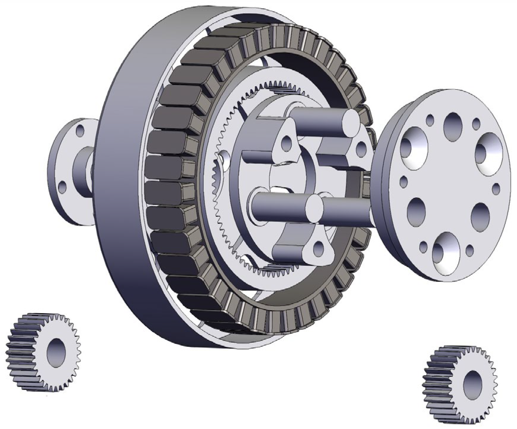
Permanent Magnet Synchronous Motors (PMSMs) are renowned for their high efficiency and reliability [33]. The robotic joints studied in this work employ PMSMs as their core drive actuators. The robotic joint motor features a compact integrated structure (Figure 2), comprising three essential components: a multi-pole permanent magnet synchronous motor (PMSM) with optimized magnetic circuit design, a high-torque-density planetary gear reducer, and precision-manufactured stator–rotor assemblies. The mathematical modeling procedure is developed through the following stages.
The electromagnetic coupling relationship of a robotic joint motor under the d-q rotating reference frame can be described as:
U d = L d i d d t + R i d ω e L i q U q = L d i q d t + R i q + ω e L i d + ω e φ m
As illustrated in Figure 2, the joint motor employs a surface-mounted permanent magnet synchronous motor (SPMSM) configuration, where the d-axis and q-axis parameters exhibit identical resistance R and inductance L values due to symmetrical magnetic circuit design. U d and U q are stator voltages in rotating reference frame, i d and i q are current components along respective axes, φ m denotes permanent magnet flux linkage, and ω e represents electrical angular velocity. The electromechanical dynamics are governed by the following motion equation:
J d ω d t = 3 2 n p φ m i q T L T f r i +
where J and T L denote the inertia and torque of the load referred to the motor side, respectively. In robotic joint motor control systems, these two parameters exhibit time-varying characteristics that necessitate dynamic compensation. n p indicates pole pairs, represents unmodeled dynamics, and T f r i stands for the friction torque, which can be characterized by the dynamic LuGre friction model to account for its nonlinear time-varying properties under varying velocity conditions
d z 0 d t = ω ω g ω z 0
σ 0 g ω = F C + F S F C e ( ω ω s ) 2
T f r i = λ σ 0 z 0 + σ 1 d z 0 d t + σ 2 ω
Equation (3) is the dynamic equation for the average deformation of contact surface bristles, where z 0 denotes the state variable. In Equation (4), the nonlinear function g ω represents the friction effect, F C stands for the coulomb friction force, F S indicates the maximum static friction force, and ω s corresponds to the Stribeck velocity. In Equation (5), λ is the friction coefficient, while σ 0 , σ 1 , and σ 2 represent the stiffness coefficient, damping coefficient, and viscous friction coefficient, respectively.
This paper aims to design a discrete-time speed controller to ensure the high-precision tracking of the load speed to the reference command, even in the presence of unmodeled dynamics and external disturbances.

3. Characteristic Modeling and Controller Design

3.1. Characteristic Modeling

As revealed by Equations (1)–(5), the joint motor system exhibits a nonlinear time-varying mathematical model. However, designing control laws based on such models to enhance control performance faces challenges such as algorithmic complexity, heavy computational loads, and implementation difficulties on low-computational-power microcontrollers. To address these limitations while improving the control performance of joint motor drives, this work utilizes a characteristic modeling methodology tailored to the controlled plant. Under identical control inputs, the characteristic model demonstrates output equivalence with the actual system. By encapsulating higher-order dynamic characteristics into time-varying parameters, this methodology not only streamlines controller synthesis but also ensures practical feasibility for embedded implementations.
Consider a class of nonlinear systems described by
x t ˙ = f x , x ˙ , , x n , u , u ˙ , , u n
Assumption 1
[34]. 
  • The system is strictly SISO.
  • The power of control input  u t  is 1.
  • The nonlinear function  f ·  satisfies  f · = 0  when all its arguments are zero.
  • f ·  is continuously differentiable with respect to all arguments, and its partial derivatives are uniformly bounded.
  • The inequality  f x t + t , u t + t f x t , u t < G · t  holds for a positive constant  G , where  t  denotes the sampling interval.
  • Both  u t  and all arguments of  f ·  remain bounded—a condition readily satisfiable in practical engineering scenarios.
The characteristic modeling approach is fundamentally limited to SISO systems and cannot be directly applied to MIMO systems. This limitation holds for applications including quadrotor flight control and automotive active suspension with steering coordination systems. Furthermore, the methodology inherently assumes that time-varying parameters vary slowly relative to the sampling period. When applied to systems exhibiting abrupt parameter variations, the characteristic model demonstrates degraded control performance.
Lemma 1
[29,34]. For a controlled plant governed by the nonlinear system in Equation (6) and satisfying Assumptions 1, its characteristic model can be represented by a second-order time-varying difference equation under appropriate sampling interval t
x k + 1 = α 0 k x k + α 1 k x k 1 + β 0 k u k + β 1 k u k 1
where  α 0 k ,  α 1 k ,  β 0 k , and  β 1 k  are time-varying coefficients requiring online identification. Notably, for minimum-phase systems, the term  β 1 k u k 1  in (7) can be omitted.
By measuring the system’s input–output data, we achieve online identification of its characteristic model, a direct application of Lemma 1 from characteristic modeling theory. In this design, the controlled plant is a PMSM. Through the measurement of the PMSM’s input (control voltage) and output (rotational speed), the motor dynamics are characterized by a second-order time-varying difference equation as:
ω k + 1 = α 0 k ω k + α 1 k ω k 1 + β 0 k u k
where ω k denotes the motor angular velocity and u k represents the control input. In joint motor control systems, the speed loop control cycle is typically less than 1 ms, while external disturbances exhibit time constants generally ranging from tens to hundreds of milliseconds. This temporal relationship ensures that the time-varying parameters α 0 k , α 1 k , and β 0 k evolve slowly relative to the control cycle t , making them suitable for parameter identification. Unlike previous studies [30,31,32] that employ recursive least squares (RLS) algorithms for time-varying parameter identification, this work proposes a computationally efficient gradient descent algorithm to estimate the coefficients of the linear difference equation. Let α ^ 0 k , α ^ 1 k , and β ^ 0 k represent the estimated parameters; the predictive model becomes:
ω ^ k + 1 = α ^ 0 k ω k + α ^ 1 k ω k 1 + β ^ 0 k u k
Defining the prediction error as:
χ k = ω k + 1 ω ^ k + 1
The update law for time-varying parameters is designed as follows:
α ^ 0 k + 1 α ^ 1 k + 1 b ^ 0 k + 1 = α ^ 0 k α ^ 1 k b ^ 0 k + γ 0 χ k ω k ω k 1 u k
where γ denotes the update step size (γ > 0). The characteristic model of the joint motor drive control system is formulated as:
ω k + 1 = α ^ 0 k ω k + α ^ 1 k ω k 1 + β ^ 0 k u k + d k
where d k represents the modeling error. Defining parameter estimation errors as α ~ 0 k = α 0 k α ^ 0 k α ~ 1 k = α 1 k α ^ 1 k β ~ 0 k = β 0 k β ^ 0 k , the modeling error d k can be expressed as:
d k = α ~ 0 k ω k + α ^ 1 k ω k 1 + β ^ 0 k u k
Let ω r k denote the reference command, and define the tracking error as
e k = ω r k ω k
Equation (12) can then be reformulated as
e k + 1 = α ^ 0 k e k + α ^ 1 k e k 1 β ^ 0 k u k + k d k
where k represents:
k = ω r k + 1 α ^ 0 k ω r k α ^ 1 k ω r k 1
Introducing the relationship:
δ k = k d k
Substitution into Equation (15) yields:
e k + 1 = α ^ 0 k e k + α ^ 1 k e k 1 β ^ 0 k u k + δ k
As demonstrated in Reference [35], the coefficients of the characteristic model can be preliminarily estimated with established boundedness properties: α 0 k 1,2 , α 1 k 1,0 , β 0 k > 0 , and β 0 k 1 . Since the true values of α 0 and α 1 cannot be determined a priori, their initial values are typically set at the midpoint of the specified range, i.e., α 0 0 = 1.5 and α 1 0 = −0.5. Although β 0 k 1 , excessively small values may induce control signal oscillations. Empirical evidence suggests initializing β 0 0 within the range of 0.01 to 0.1. These prior constraints enable the guaranteed boundedness of both identified parameters and parameter estimation errors through amplitude limiting. Furthermore, given the inherent boundedness of practical system variables ω r k ,   ω k , and u k , the composite uncertainty term δ k consequently remains bounded, with its absolute value constrained as δ k < ρ . Building upon these boundedness properties, the control task of this study is to devise an appropriate control law that ensures the robust tracking performance of motor angular velocity toward reference commands, particularly under conditions of load parameter variations and external disturbances.
It should be emphasized that the proposed control law is designed from the characteristic model, rather than the dynamics Equations (1)–(5). The structural form of this characteristic model is given by Equation (9), with its time-varying coefficients obtained through online identification using actual system input/output data. The dynamics equations were provided solely for the validity verification of the characteristic modeling approach. Simulation studies were conducted within the MATLAB/Simulink environment. The servo system dynamics model, governed by Equations (1)–(5), served as the simulation target, with system parameters summarized in Table 1. Identical sinusoidal input signals were applied to both the servo system dynamics model and the characteristic model. The coefficients of the characteristic model ( α ^ 0 , α ^ 1 and β ^ 0 ) were obtained using the gradient-based identification algorithm detailed in Equation (11).
The simulation results are presented in Figure 3. Comparing the output ω of the dynamics model with the output ω ^ of the characteristic model reveals that the characteristic model output closely tracks the dynamics model output. Furthermore, the characteristic parameters rapidly converged and demonstrated the capability to adequately represent non-linear friction characteristics. Consequently, the modeling error was maintained within acceptable bounds throughout the simulation. These results demonstrate that the characteristic model effectively captures the input–output characteristics of the original system.

3.2. Controller Design

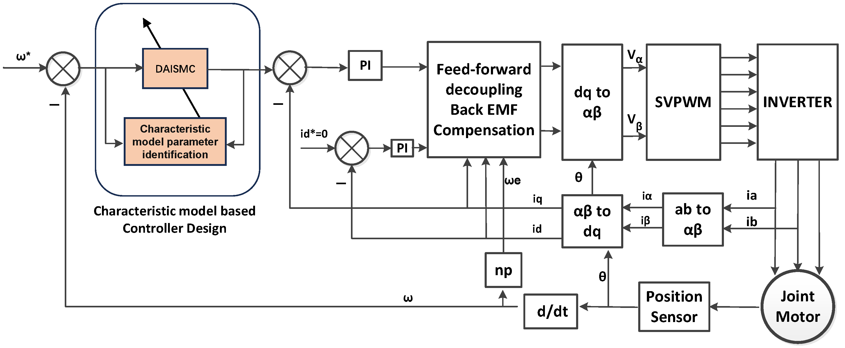
This section presents the design of a DAISMC tailored for computationally efficient implementation on low-performance microcontrollers. The overall control system architecture is depicted in Figure 4. A cascaded structure is employed. The inner current loop utilizes a conventional PI controller combined with feedforward compensation techniques, as detailed in reference [36], to achieve the decoupled control of the dq-axis currents. Within the speed control loop, time-varying parameters of the characteristic model are identified online using a gradient-descent method based on the tracking error and prior control law. These identified parameters are then fed into a DAISMC. This controller subsequently generates the current command, enabling simultaneous online parameter identification and robust control.
Conventional sliding mode surfaces typically incorporate derivative terms, rendering them susceptible to high-frequency noise injection, which can compromise closed-loop stability in practical control implementations. To facilitate engineering realization, this study introduces an integral sliding mode surface to reduce tracking error and enhance control precision. The discrete-time integral sliding mode surface is designed as follows:
σ k = e k + γ 1 τ k
where γ 1 is a tunable coefficient ( γ 1 > 0 ) and τ k represents the cumulative tracking error:
τ k = τ k 1 + e k
Remark 1.
The initial value τ 0 influences the initial trajectory of the tracking error. Selecting
τ 0 = 1 γ 1 e 0
ensures the error trajectory starts precisely on the sliding manifold, minimizing the settling time. If  τ 0  is not initialized according to (21), an explicit reaching phase occurs, whereby the tracking error trajectory converges to a neighborhood of the sliding manifold within a finite number of sampling intervals.
Taking the forward difference of (19) yields:
σ k + 1 = e k + 1 + γ 1 τ k + 1
Substituting (20) into (22) gives:
σ k + 1 = e k + 1 + γ 1 τ k + e k + 1 = ( γ 1 + 1 ) e k + 1 + γ 1 τ k
The further substitution of Equation (18) into (23) results in:
σ k + 1 = ( γ 1 + 1 ) [ α ^ 0 k e k + α ^ 1 k e k 1 β ^ 0 k u k + δ k ] + γ 1 τ ( k )
where δ k represents bounded disturbances. From Equation (19):
γ 1 τ k = σ k e k
Inserting (25) into (24) yields:
σ k + 1 = ( γ 1 + 1 ) [ α ^ 0 k e k + α ^ 1 k e k 1 1 γ 1 + 1 e k + δ k β ^ 0 k u k ] + σ k
The adaptive sliding mode control law is then formulated as:
u k = u e q k + u s k
with the equivalent control component:
u e q k = 1 β ^ 0 k α ^ 0 k e k + α ^ 1 k e k 1 1 γ 1 + 1 e k
and the robust switching control component:
u s k = 1 β ^ 0 k ρ · s g n σ k
where s g n ( · ) denotes the signum function, and ρ is the boundary of δ k . u s k demonstrates symmetry in the vicinity of sliding surfaces. Figure 5 illustrates the structure of the DAISMC. As evident, this controller exhibits a streamlined structure with minimal computational overhead, rendering it well-suited for deployment on resource-constrained, low-power microcontrollers.
Remark 2.
During controller implementation, the hyperbolic tangent function t a n h ( · ) can be substituted for the signum function  s g n ( · )  to mitigate chattering phenomena. In the characteristic model, the identified control input gain coefficient  β ^ 0 k  is significantly smaller than 1. Fluctuations in  β ^ 0 k  can induce excessive variations in the control input. To circumvent this issue and enhance control performance, the gain preceding  u k  in Figure 5 can be modified to  1 β ^ 0 k + λ , where  λ  is a small positive constant (e.g.,  λ  = 0.01).

3.3. Stability Analysis

Theorem 1.
Consider the system described by Equation (18), satisfying δ k < ρ . Under the designed discrete integral adaptive sliding mode control law (Equations (27)–(29)) acting on the sliding surface defined by Equation (19), the reachability of the sliding manifold is guaranteed.
Proof of Theorem 1.
Define the Lyapunov function candidate as:
V k = 1 2 σ k 2
The convergence of the system trajectory to the sliding manifold requires satisfying the condition:
V k = 1 2 σ k + 1 2 1 2 σ k 2 < 0
This condition is equivalent to:
σ k + 1 < σ k
Substituting the control law (Equations (27)–(29)) into Equation (26) yields:
σ k + 1 = ( γ 1 + 1 ) { δ k ρ · s g n σ k } + σ k
Thus,
σ k + 1 σ k = ( γ 1 + 1 ) { δ k ρ · s g n σ k }
Given the disturbance bound δ k < ρ :
ρ < δ k < ρ
Case 1: σ(k) > 0
σ k + 1 σ k = ( γ 1 + 1 ) [ δ k ρ ] < 0   ( since   δ k < ρ )
Case 2: σ(k) < 0
σ k + 1 σ k = ( γ 1 + 1 ) [ δ k + ρ ] > 0   ( since   δ k > ρ )
Both cases (Equations (36) and (37)) imply:
σ k + 1 < σ k
Therefore, the reachability of the sliding manifold is guaranteed. This completes the proof. □
Assume the system remains on the sliding surface. Then,
e k + γ 1 τ k = 0
Thus,
e k = γ 1 τ k
Substituting Equation (40) into the definition of Equation (20) yields:
τ k = τ k 1 γ 1 τ k
Therefore,
τ k = 1 1 + γ 1 τ k 1
Equation (42) is a first-order linear homogeneous difference equation. Its solution is
τ k = 1 1 + γ 1 k τ 0
where τ 0 denotes the initial cumulative error. Substituting Equation (40) into Equation (43) yields:
e k = γ 1 1 1 + γ 1 k τ 0
Since γ 1 > 0 , the sequence
lim k 1 1 + γ 1 k = 0
Therefore,
lim k e k = l i m k γ 1 1 1 + γ 1 k τ 0 = 0
When the sliding surface condition σ k = 0 holds, the error e k converges exponentially to zero. The convergence rate is governed by γ 1 , and a larger γ 1 accelerates convergence.

3.4. Numerical Simulation

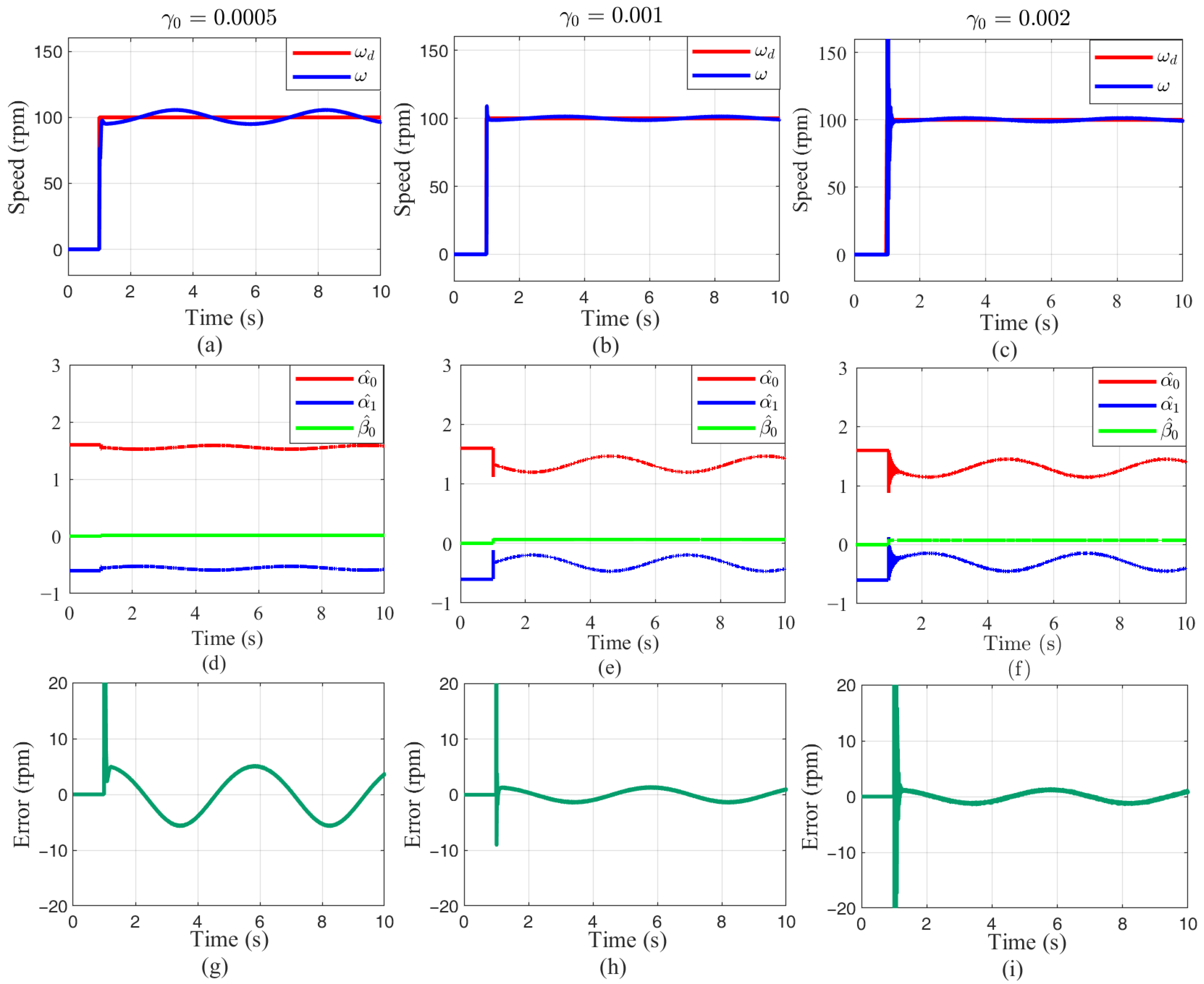
To investigate the proposed control algorithm, simulation experiments were conducted in the MATLAB/Simulink environment using the model parameters listed in Table 1. A step command of 100 rpm was applied, with a time-varying load torque T L = 1.0 s i n ( ω 8 t )   N · m introduced during simulations. While γ 1 = 0.3 was fixed, the control parameter γ 0 governed the update rates of the characteristic model coefficients α ^ 0 , α ^ 1 and β ^ 0 . To analyze the impact of γ 0 on control performance, simulations were performed for γ 0 = 0.0005 , γ 0 = 0.001 , and γ 0 = 0.002 without activating the sliding mode control law us, as shown in Figure 6.
The simulation results for different γ 0 values are organized in three columns in Figure 6. Increasing γ 0 enhances the tracking of time-varying load torque T L by α ^ 0 , α ^ 1 , and β ^ 0 , progressively reducing control error. However, excessively large γ 0 (e.g., γ 0 = 0.002) causes oscillations in the identified coefficients without further reducing control error. The control performance improves as α ^ 0 , α ^ 1 , and β ^ 0 respond more rapidly to uncertain dynamics.
With the parameter ρ set to 30 in the DAISMC scheme, Figure 7 demonstrates that the addition of the sliding mode control law further suppresses the control error and improves reference tracking performance. However, this enhancement is compromised by induced chattering phenomena.
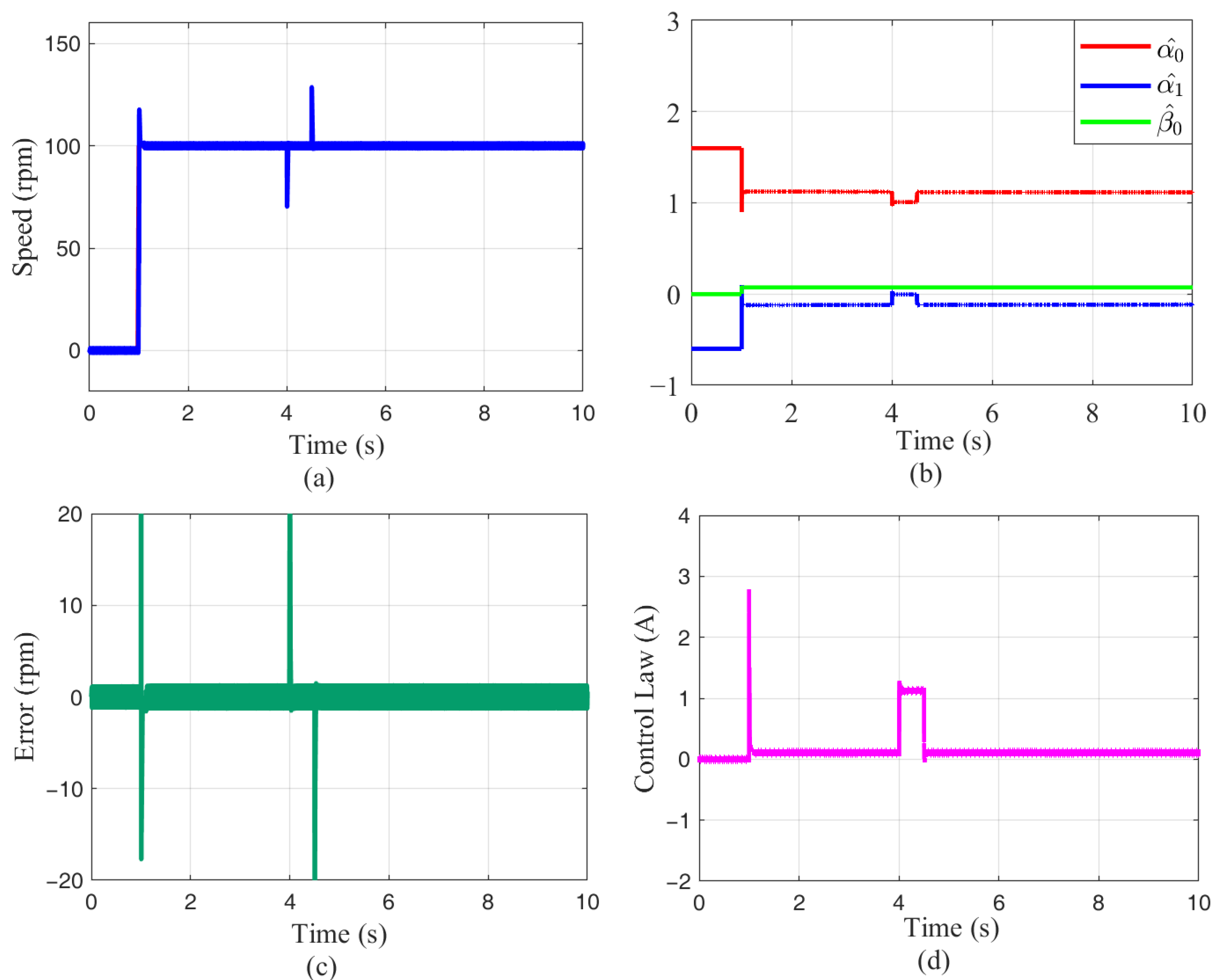
Further simulation studies were conducted with step load changes. As shown in Figure 8, a 0.5 N · m load torque was applied at t = 4 s and removed at t = 4.5 s. Although the characteristic model coefficients reflect load transients, they fail to provide timely compensation. The disturbance magnitude exceeds the boundary of ρ , causing two significant tracking error spikes at load application/removal instants. This limitation indicates an insufficient disturbance rejection of the proposed control during abrupt loading. Increasing ρ enhances robustness but exacerbates chattering—this tradeoff can be mitigated by integrating the adaptive upper bound strategy for sliding mode control [21].

4. Implementation of the Joint Motor Drive System

The hardware architecture of the joint motor drive system is depicted in Figure 9. It comprises three primary functional modules: a power supply circuit module, a communication and speed control module based on AT32F423 microcontroller (a product of Artery Technology Company, Chongqing, China), and a Field-Oriented Control (FOC) and protection module based on LKS32MC070 microcontroller (a product of LINKO Semiconductor Company, Nanjing, China). The design implementations of these modules are elaborated as follows.

4.1. Power Supply Design

The drive module is designed to operate from a DC input voltage range of 15–60 V. To meet diversified voltage requirements +12 V for MOSFET drivers, +5 V for the LKS32MC070 MCU and magnetic encoder, and +3.3 V for the AT32F423 MCU and communication interfaces, a three-stage step-down power architecture is implemented.
The DC input undergoes primary filtering via bus capacitors. Due to PCB spatial constraints prohibiting electrolytic capacitors, parallel arrays of 1210-package ceramic SMD capacitors provide bus filtering functionality. The primary voltage regulation stage utilizes a SCT2A25 DC-DC buck converter to stabilize the variable 15–60 V input to a regulated +12 V output, selected for its high efficiency across wide voltage differentials. Subsequent voltage conversions employ low-dropout (LDO) regulators for noise-sensitive MCU power rails: the +12 V to +5 V conversion utilizes a 78M05 converter, while the +5 V to +3.3 V conversion is implemented using an AMS1117-3.3 converter (a product of Advanced Monolithic Systems Company, Sunnyvale, CA, USA).

4.2. Communication and Speed Control Module Design

This subsystem centers on an ARM Cortex-M4-based AT32F423 controller (4 mm × 4 mm × 0.8 mm, 150 MHz clock with FPU) capable of executing computationally moderate control algorithms. It performs the characteristic-model parameter identification and adaptive integral sliding-mode control algorithms. The AT32F423 interfaces with the LKS32MC070 FOC controller through dual communication channels: an 8 MHz SPI bus handles high-speed exchange of periodic data (including velocity commands, real-time motor speed, and phase currents), while a 115.2 kbps UART transmits low-speed commands and status data (such as enable signals, status indicators, and fault flags). To alleviate computational burdens on the LKS32MC070, all external communications are managed exclusively by the AT32F423 via a CAN bus interface implemented with the SN65HVD230 transceiver (a product of Texas Instruments Company, Dallas, TX, USA) and an RS-422/RS-485 interface using the ADM3485E transceiver (a product of Analog Devices Company, Wilmington, DE, USA).

4.3. FOC and Protection Module Design

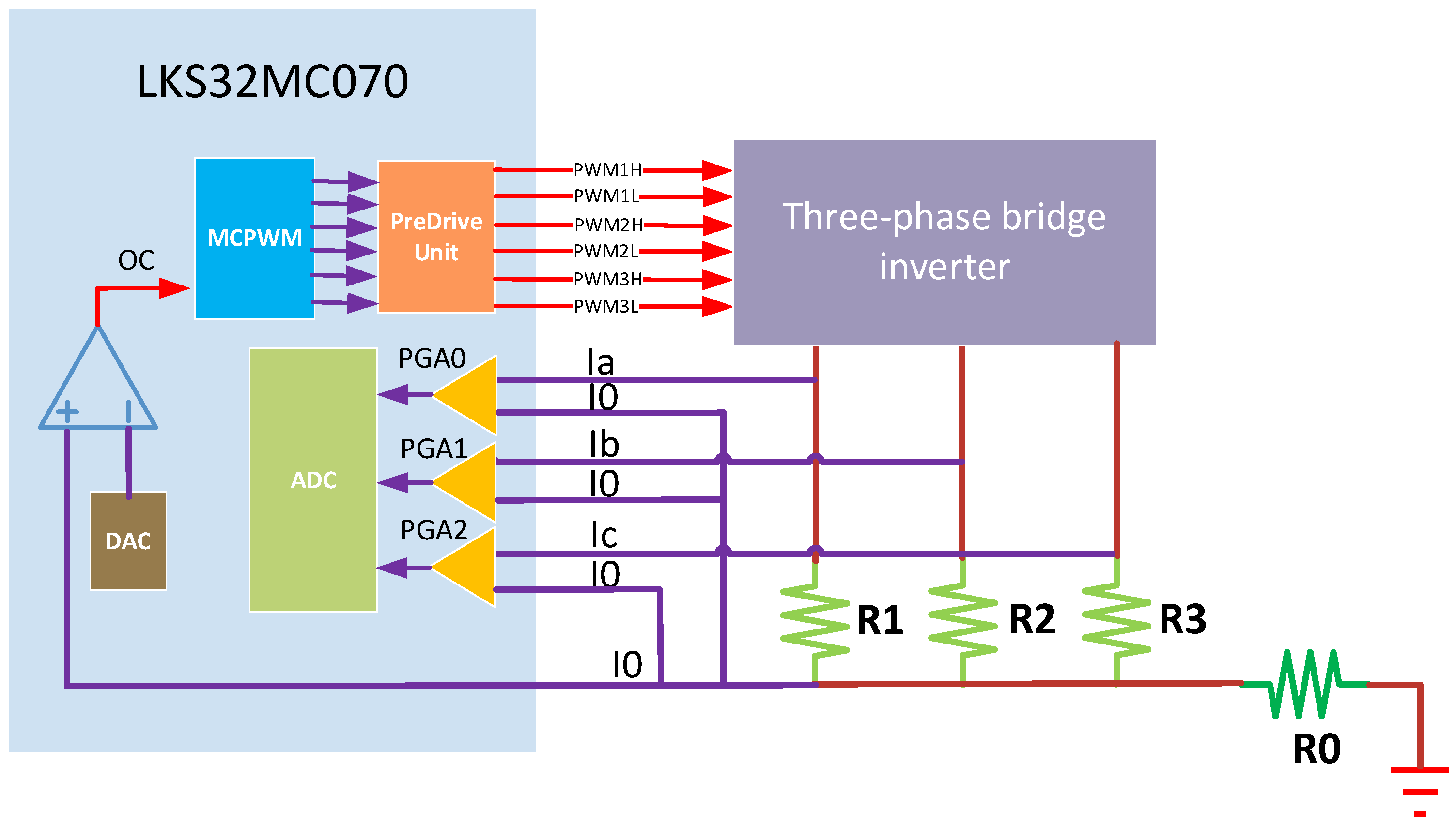
Joint motor FOC and protection are managed by the ARM Cortex-M0-based LKS32MC070 as shown in Figure 10. Despite its computational limitations, the LKS32MC070 processor minimizes external circuitry through integrated motor control peripherals: six MCPWM output channels incorporate internal pre-driver processing (featuring interlocking, dead-time insertion, and amplification) enabling direct MOSFET gate connection without external drivers. The power stage employs HYG053N10 MOSFETs (a product of Huayi Microelectronics Company, Xi’an, China) rated at 100 V/95 A continuous current. Current sensing implementations include: (1) Phase current measurement via shunt resistors (R1-R3), where differential voltages directly interface with the internal PGA accepting bipolar inputs, eliminating external signal conditioning; (2) DC-bus overcurrent protection using shunt resistor R0, where an integrated comparator continuously evaluates sampled voltage against a DAC-generated threshold, triggering immediate PWM shutdown. Position feedback is provided by a 14-bit MA732 magnetic encoder (a product of Monolithic Power Systems Company, Kirkland, DC, USA) delivering angular position data via SPI with 10 μs end-to-end acquisition–transmission latency.
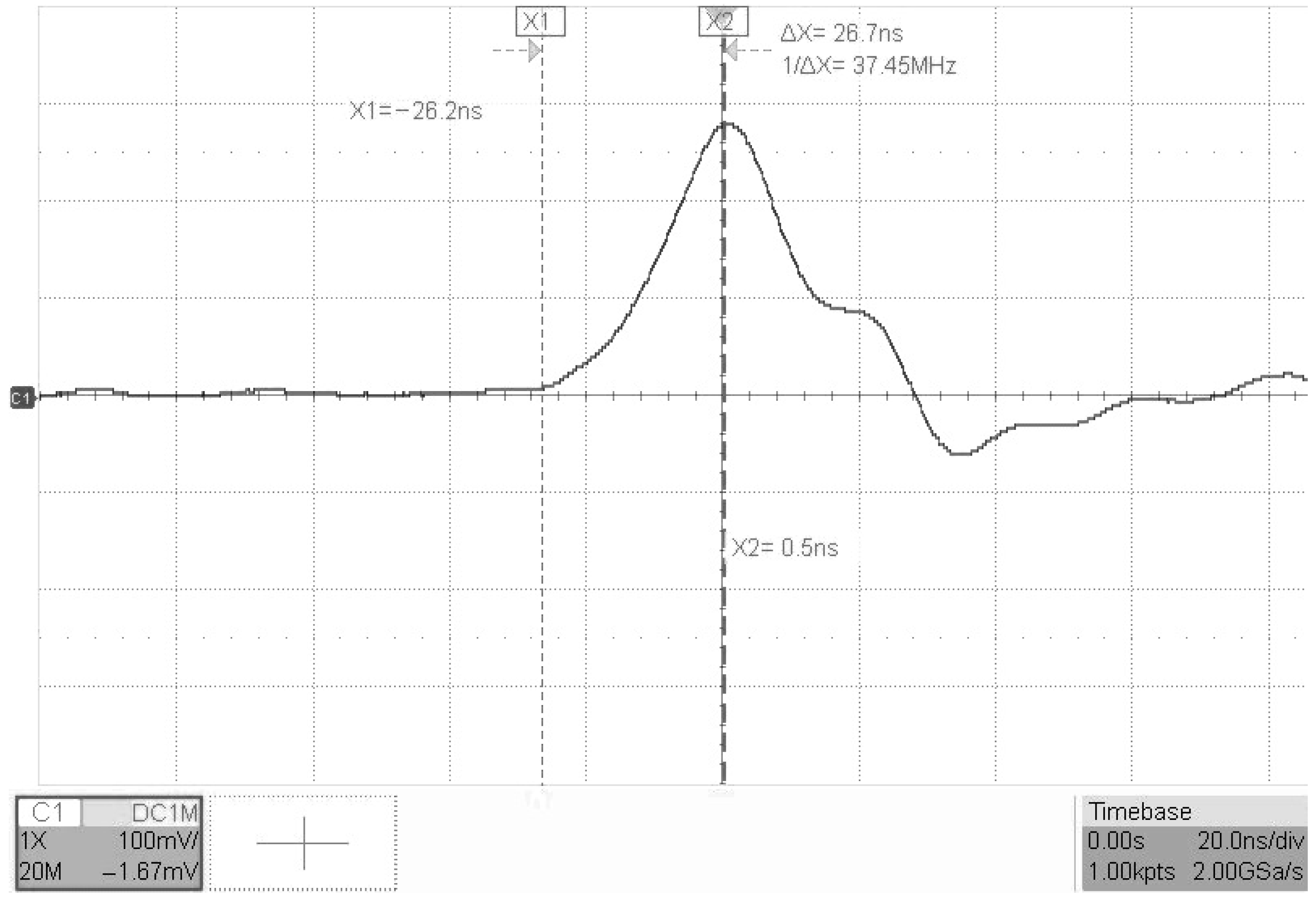
DC-bus overcurrent protection typically achieving a response time within 200 ns. The protection system’s reaction speed is reducible to under 50 ns when activating the processor’s fast comparator mode. Figure 11 exhibits the voltage waveform across the DC-link sampling resistor during overcurrent protection testing in this mode. The interval between current rise initiation and turn off measures ≤26.7 ns. As established by the series reliability model, reducing discrete components enhances system reliability. Eliminating the comparator and voltage reference circuit in the proposed design improves reliability over conventional approaches.

4.4. Hardware Implementation

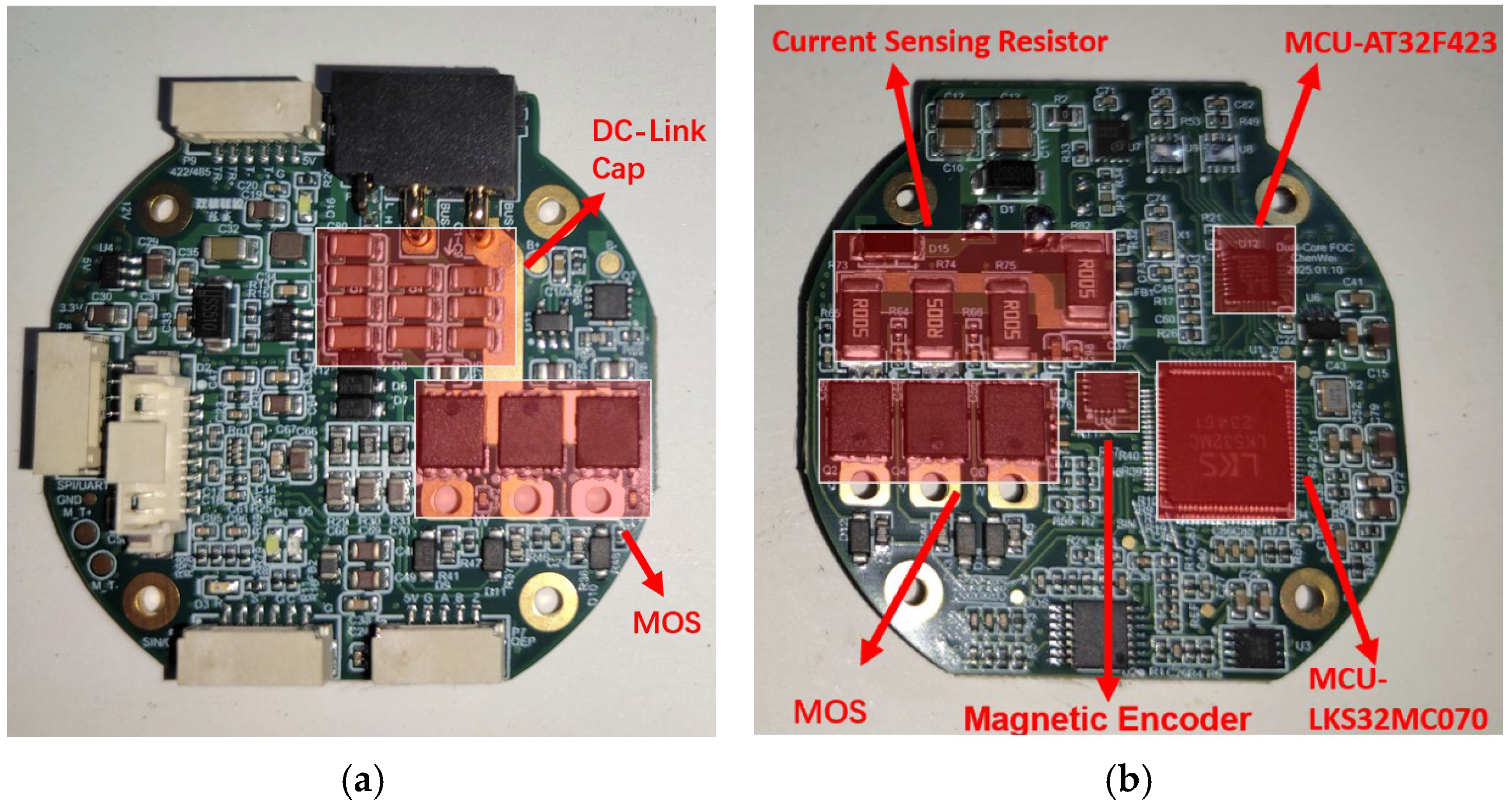
To accommodate confined joint motor cavities, a six-layer PCB measuring 47 mm × 47 mm conforms precisely to the motor’s profile. Figure 12 shows the physical implementation of the joint motor drive module that features a symmetrical in shape. The hardware configuration features dedicated interfaces: a black XT30 connector for DC power input alongside a white multi-purpose port handling both communication and debugging functions. Strategic component placement optimizes signal integrity and thermal management: DC bus capacitors are positioned adjacent to the power inlet; upper bridge-leg MOSFETs populate the module’s front-side while lower bridge-leg counterparts are surface-mounted on the rear; current-sense resistors maintain immediate proximity to lower MOSFETs. Notably, the magnetic position encoder requires central placement within ≤10 mm of shaft-end magnets, with all high-speed communication traces (MA732-LKS32MC070 and LKS32MC070-AT32F423) co-routed on the same PCB layer to minimize electromagnetic interference. The material cost for microcontrollers AT32F423 and LKS32MC070 in this solution is approximately 2.40 USD, compared to traditional DSP/FPGA solutions requiring at least 6.00 USD (including pre-drivers and operational amplifiers). This design reduces joint motor drive costs by approximately 36%.

4.5. Software Implementation

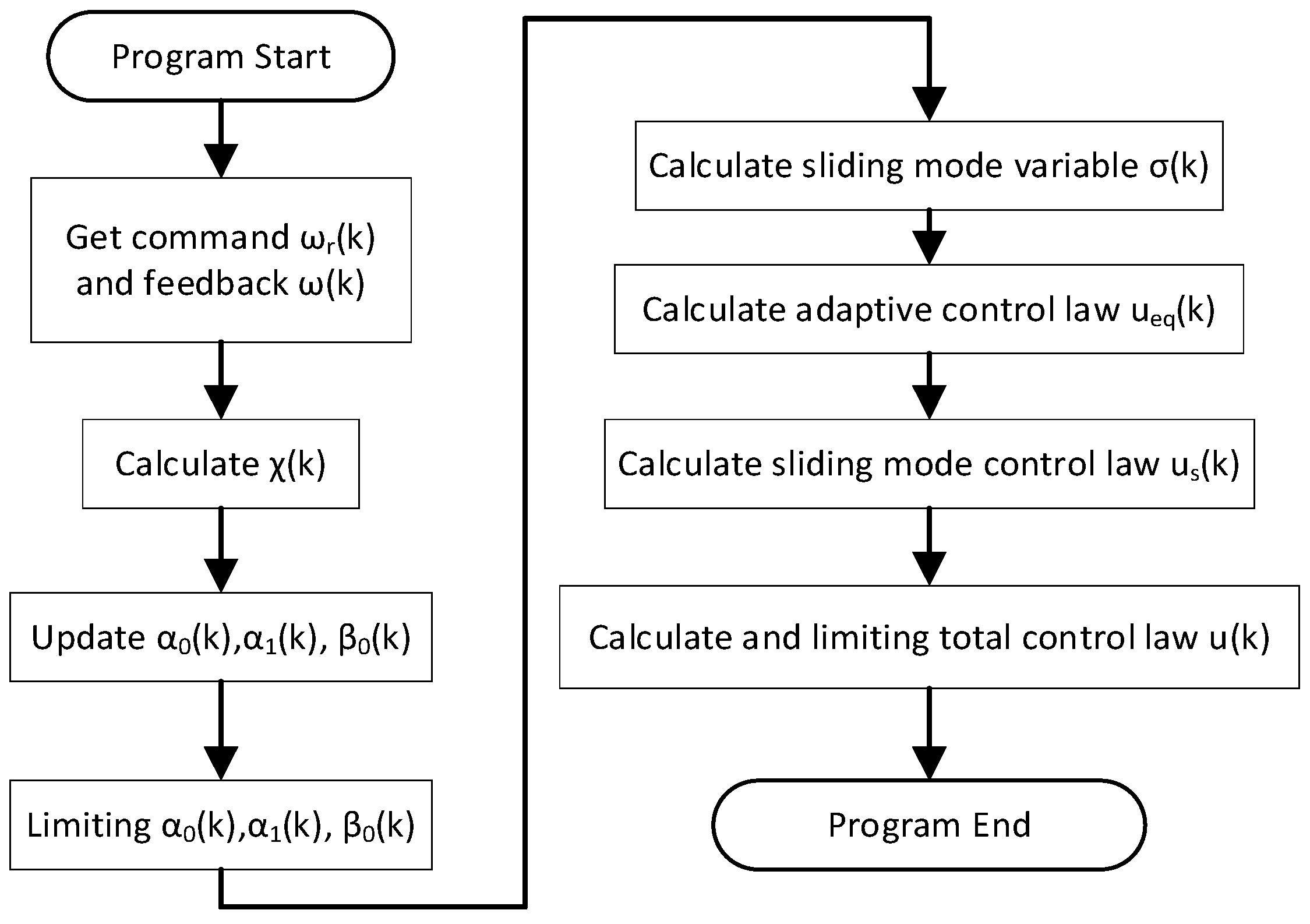
Field-Oriented Control (FOC), current-loop regulation, and fault detection/protection routines are executed on the LKS32MC070 microcontroller. These routines are completed within 63 μs—occupying 63% of the 100 μs current control cycle. The AT32F423 microprocessor handles higher-level functions including speed-loop control and communication routines. During its boot sequence, it sequentially initializes peripherals, loads control parameters, and configures interrupt handlers. Two critical interrupts are implemented: a communication interrupt for processing inbound external commands and a 100 μs-period timer interrupt that executes the characteristic model-based integral adaptive sliding mode control algorithm (Figure 13).
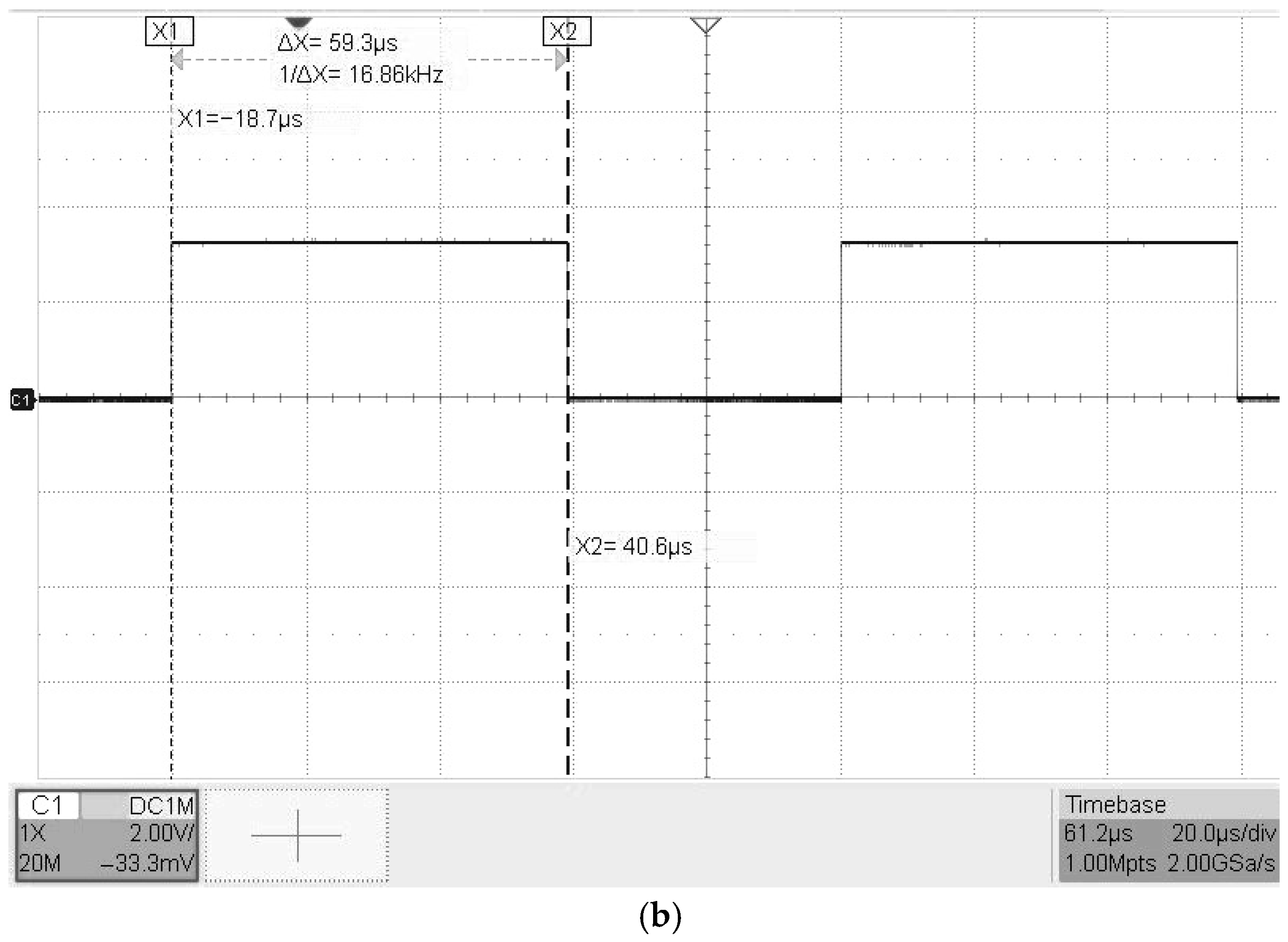
To measure algorithm execution time, we triggered a designated MCU I/O pin high at program entry and de-asserted it upon exit. The pulse width of this signal (Figure 14) directly corresponds to execution duration. The DAISMC execution time is 46.2 μs, while the Model Predictive Control (MPC) execution time is 59.3 μs. Thus, DAISMC achieves ≈13.1% CPU usage reduction compared to conventional MPC implementation.

5. Experimental Validation

5.1. Experimental Setup

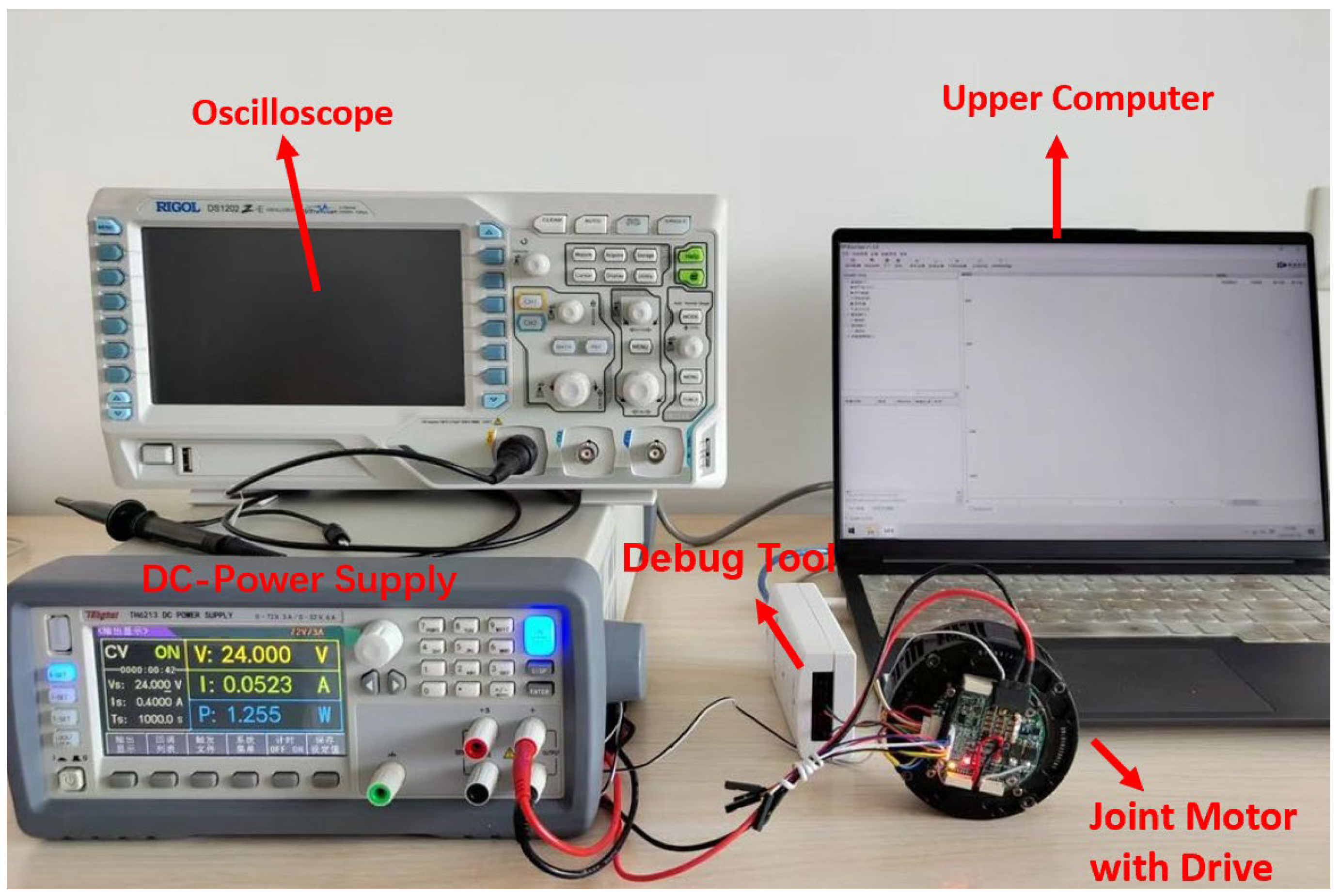
To validate the performance of the proposed control algorithm and joint motor drive module, an experimental testbed was constructed as illustrated in Figure 15 The joint drive module was powered by a programmable DC source operating at 24.0 V. Critical electrical signals were monitored and verified using an oscilloscope to ensure operational integrity. Real-time operational data acquisition at 10 kHz sampling frequency was implemented via an RTT viewer channel through a J-LINK debug probe connecting the host PC and drive module. The developed hardware prototype drives a GIM6010-8 joint motor (a product of SteadyWin Company, Nanchang, China) with an integrated planetary gearbox, whose specifications are detailed in Table 2.

5.2. Control Methods for Comparison

Benchmark experiments were conducted on the developed joint motor drive platform to evaluate three speed-loop controllers: a conventional PI controller, a CFBSC [17], and the proposed DAISMC. Experimental configurations maintained identical current-loop parameters k p c = 0.75 and k i c = 0.098 executed on the LKS32MC070 microcontroller while implementing distinct speed-loop controllers: standard PI k p v = 1.17 , k i v = 0.029 , CFBSC ω n = 1000 , ξ = 0.8 , k s = 0.1 , p = 120 , and proposed DAISMC γ 0 = 0.001 , γ 1 = 0.3 , λ = 0.01 .
Friction couples with transmission backlash, significantly accentuating their combined adverse effects on tracking precision. Accordingly, sinusoidal excitation tests were conducted to evaluate how the boundary coefficient ρ affects tracking performance (Figure 16). Larger ρ values enhance disturbance rejection at the cost of intensified chattering. When ρ increases from 10 to 70, the maximum absolute error (MAE) progressively decreases. However, the root mean square error (RMSE) first declines then rises within this range. As ρ increases from 50 to 70, MAE reduction saturates while RMSE increases substantially. Therefore, ρ = 50 is selected as the optimal trade-off between disturbance rejection and chattering suppression. The performance metrics under different ρ are listed in Table 3.

5.3. Experimental Results and Discussion

5.3.1. Step Response Analysis Under No-Load Conditions

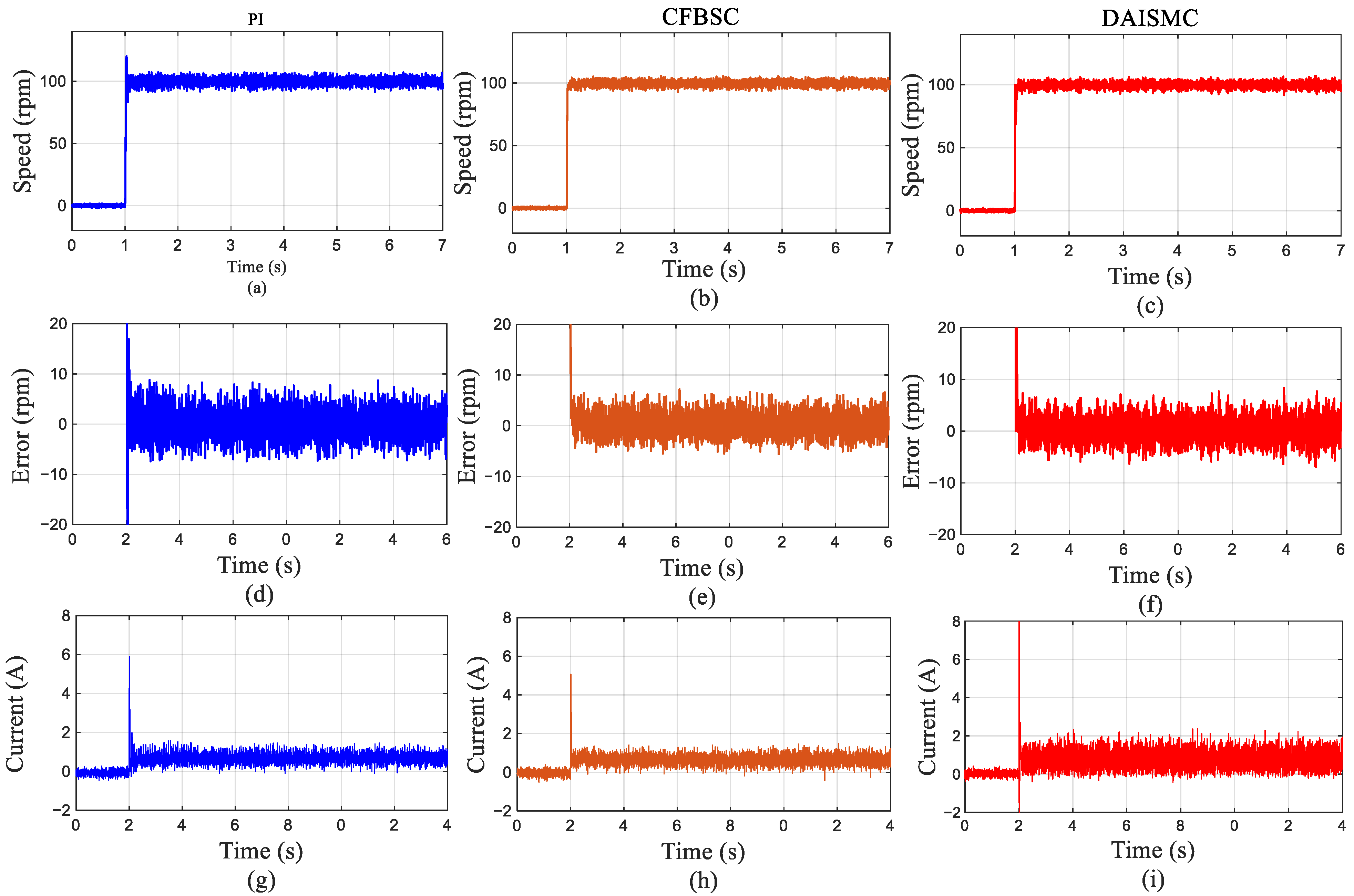
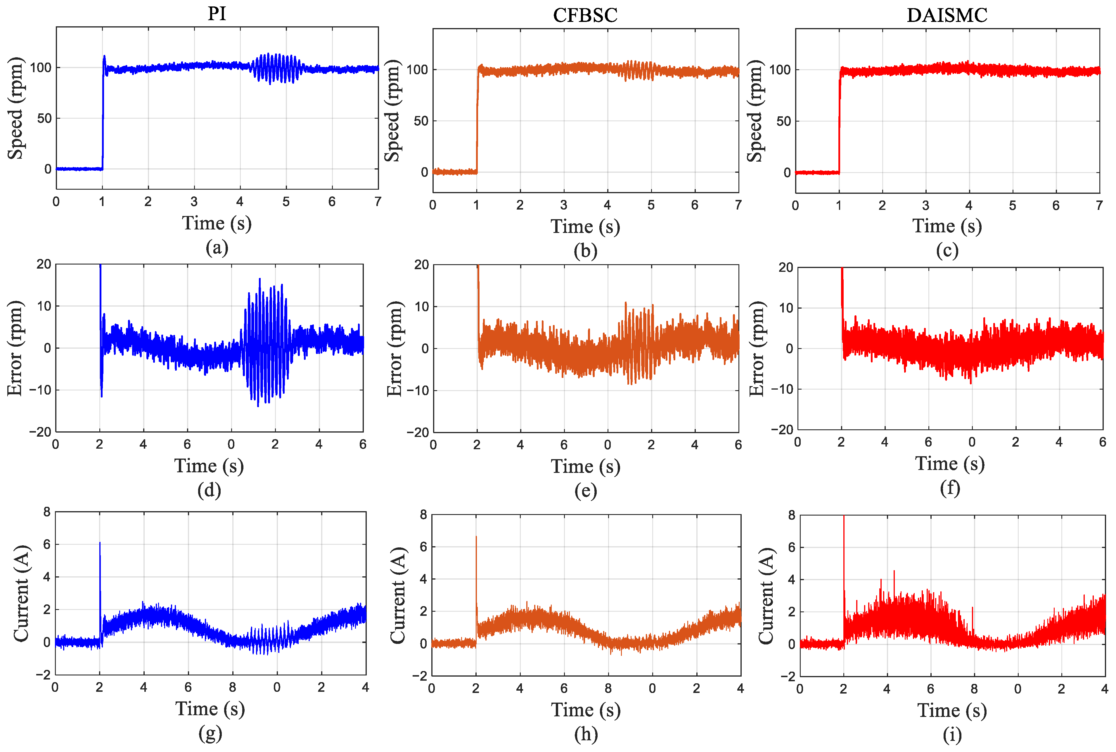
As illustrated in Figure 17, the system responses under PI controller (blue), CFBSC (orange), and DAISMC (red) control are compared. A step speed command from 0 to 100 rpm (10.46 rad/s) was applied at t = 1 s, demonstrating that all controllers had achieved trajectory tracking. Key performance metrics reveal distinct dynamic and steady-state characteristics across controllers.
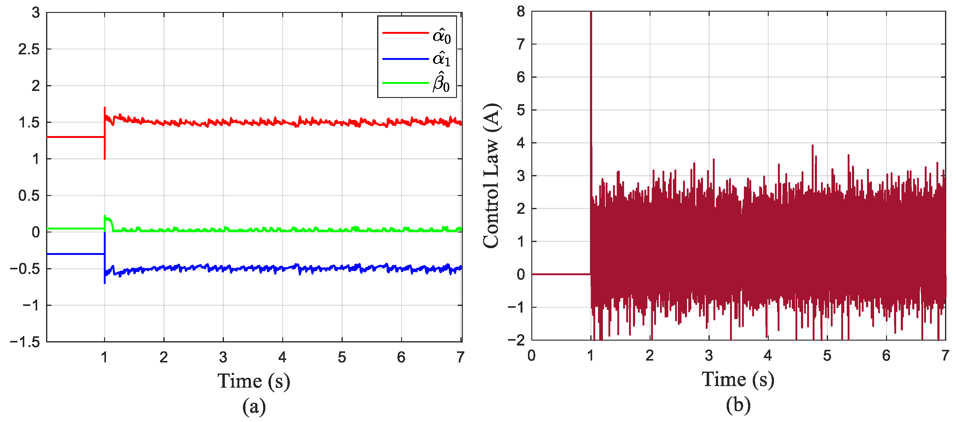
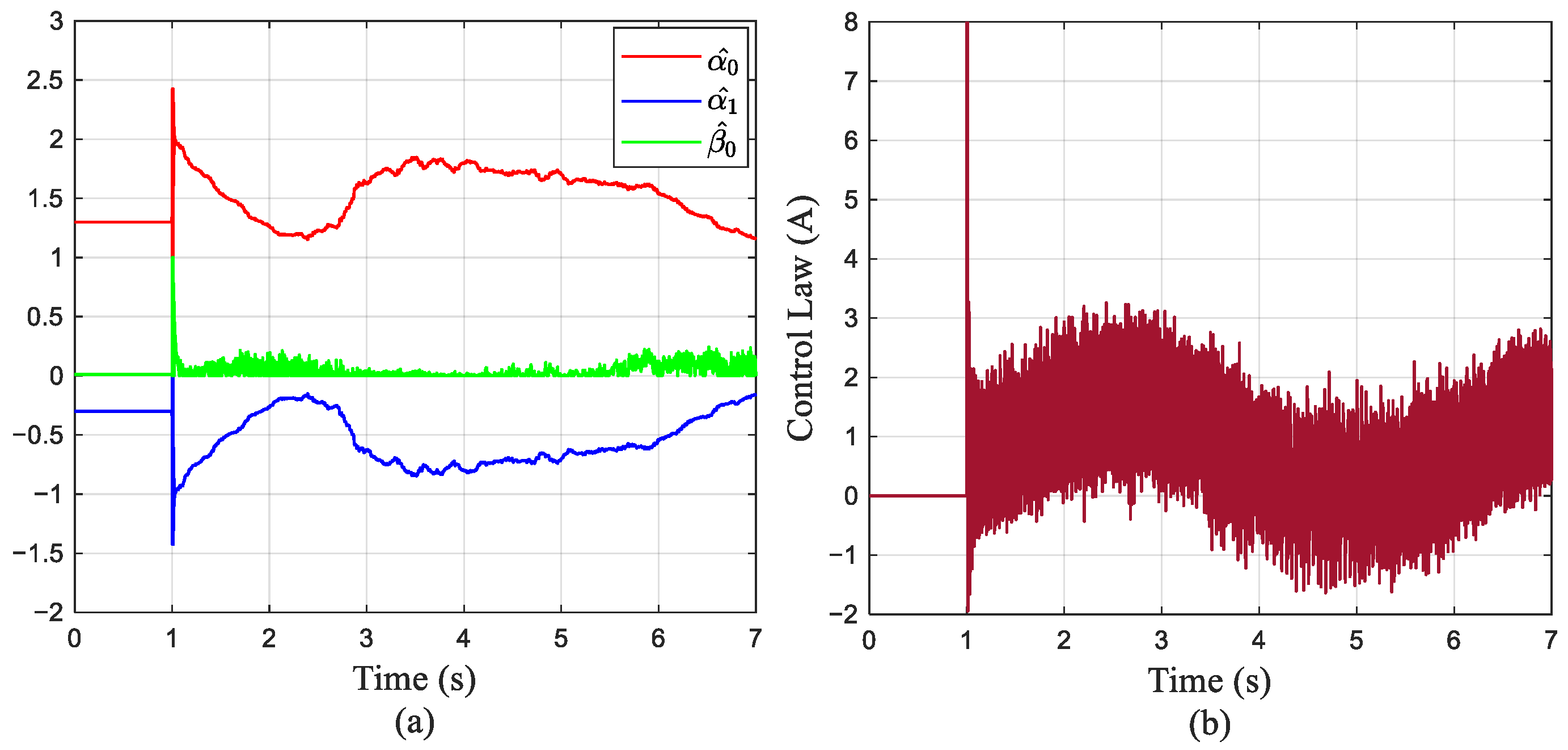
Under a step reference of 100 rpm, the PI controller exhibits the longest rise time (7 ms), while CFBSC and DAISMC achieve comparable rise times of 5 ms. The overshoot values for the three controllers are 20.13%, 5.64%, and 4.21%, respectively. Despite no-load operation, friction and backlash effects persist due to the integrated planetary gearhead in the joint motor. The PI control demonstrates sustained oscillations with a steady-state absolute maximum error (SAME) of 0.91 rad/s and steady-state root mean square error (SRMSE) of 0.31 rad/s. The adaptive mechanism in CFBSC improves precision, yielding SAME = 0.68 rad/s and SRMSE = 0.22 rad/s. Although DAISMC delivers similar performance to CFBSC, marginally larger errors (SAME = 0.72 rad/s, SRMSE = 0.24 rad/s) are observed due to chattering-induced fluctuations. The characteristic model coefficients and control law implementation for DAISMC are illustrated in Figure 18. Quantitative step response metrics are compared in Table 4.

5.3.2. Step Response Analysis Under Loaded Conditions

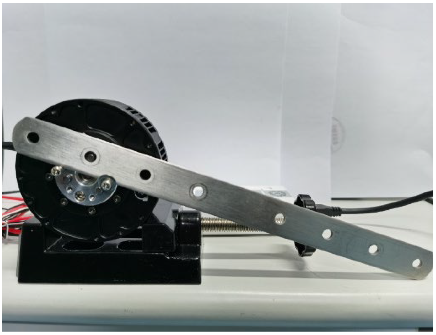
Loading tests were performed with unchanged controller parameters. As configured in Figure 19, a slender aluminum structural arm (hereinafter referred to as the structural arm) was mounted directly onto the joint motor output shaft to simulate robotic mechanical leverage. The load inertia: 3.56 × 10 3 k g · m 2 ; the time-varying load torque T L = 0.85 s i n ( ω i t )   N · m , where i is the gear ratio of planetary reducer and i = 8 . This setup enables a comparative evaluation of the three control algorithms’ time-varying disturbance rejection capabilities.
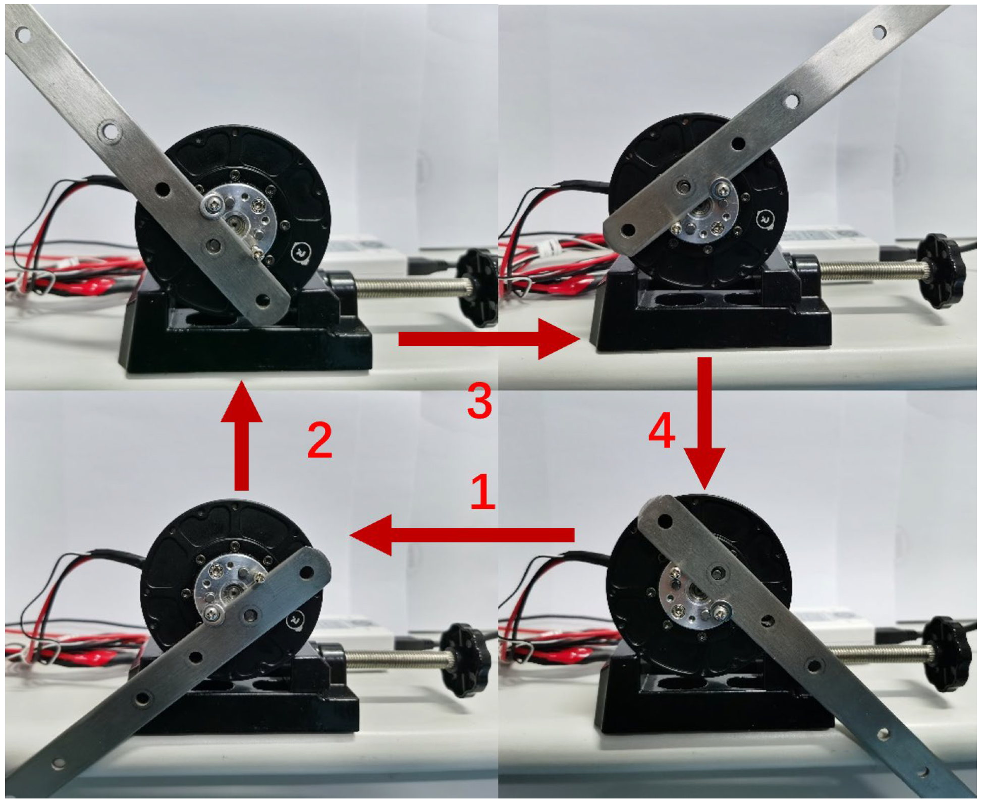
The joint motor rotates clockwise (Figure 20) with the structural arm initially perpendicular to the ground. During the 1→2→3 trajectory segment, the motor overcomes load torque with negligible backlash. Conversely, in the 3→4→1 segment where the motor transitions from motoring to braking mode, backlash and friction significantly impact system performance during operational state switching. This test configuration effectively validates controller performance under time-varying load torque and unmodeled dynamics.
As demonstrated in Figure 21, the three controllers maintain identical rise times to no-load conditions during step response. Overshoot values are reduced to 12.39%, 4.85%, and 3.93% (representing decreases of 7.74%, 0.79%, and 0.28% respectively) under loaded operation. During the 3→4→1 operational segment (Figure 20), the motor transitions from driving to braking mode. With PI control, backlash and friction induce oscillations, increasing SAME by 0.82 rad/s and SRMSE by 0.11 rad/s. CFBSC suppresses oscillations, limiting SAME and SRMSE increases to 0.44 rad/s and 0.09 rad/s. When utilizing DAISMC, the characteristic model coefficients effectively adapt to load variations and unmodeled dynamics (Figure 22); meanwhile, the sliding-mode control law further suppresses modeling errors. It restricts error increases to merely 0.03 rad/s (SAME) and 0.01 rad/s (SRMSE). The step response performance metrics under loaded conditions are listed in Table 5. Comparative no-load/loaded tests confirm that DAISMC delivers the highest robustness against load disturbances and unmodeled dynamics among the three controllers.
The experimental results demonstrate that the proposed characteristic model-based DAISMC exhibits superior performance in tracking step signals under no-load/loaded conditions. It effectively suppresses unmodeled dynamics (e.g., friction and backlash), tolerates characteristic modeling errors, and demonstrates markedly enhanced tracking accuracy relative to conventional PI control and CFBSC.

6. Conclusions

This study overcomes computational and nonlinearity challenges in compact robotic drives through a co-designed characteristic model-based framework, achieving real-time 10 kHz online parameter identification that maintains ≤0.25 rad/s speed tracking error (SRMSE) under variable loads while reducing computational load by 13.1% on dual-ARM Cortex-M4/M0 processors versus MPC implementations, alongside 36% cost reduction via integrated hardware (47 × 47 × 12 mm3) compared to DSP/FPGA solutions with sub-30 ns overcurrent protection.
Building on this foundation, we will synthesize characteristic modeling with adaptive upper-bound sliding mode and higher-order sliding mode techniques to reduce chattering while preserving robustness. Further research will develop learning-based parameter identification for enhanced transient adaptation under impact loads and implement distributed drive architectures for multi-joint collaborative robots, addressing thermal constraints through advanced cooling integration.

Funding

This research was founded by the Start-up Fund for New Talented Researchers of Nanjing Vocational University of Industry Technology, grant number YK23-02-04, Nanjing Vocational University of Industry Technology, Nanjing, China.

Data Availability Statement

The original contributions presented in this study are included in the article. Further inquiries can be directed to the corresponding author.

Acknowledgments

This research work is supported by Jiangsu Key Laboratory of Industrial Online Detection and Intelligent Perception & Institute of Electrical Engineering, and Jiangsu Engineering Research Center of Industrial Digital Manufacturing and Application & Institute of Electrical Engineering, Nanjing Vocational University of Industry Technology, 1 Yangshan North Road, Nanjing 210023, China.

Conflicts of Interest

The author declares no conflicts of interest.

References

  1. Zhang, Q.N.; Zhang, F.F.; Mai, Q. Robot adoption and labor demand: A new interpretation from external competition. Technol. Soc. 2023, 74, 102310. [Google Scholar] [CrossRef]
  2. Xie, D.B.; Chen, L.; Liu, L.C. Actuators and Sensors for Application in Agricultural Robots: A Review. Machines 2022, 10, 913. [Google Scholar] [CrossRef]
  3. Tsuji, H.; Shii, M.; Yokoyama, S.; Takamido, Y. Reusable robot system for display and disposal tasks at convenience stores based on a SysML model and RT Middleware. Adv. Robot. 2020, 34, 250–264. [Google Scholar] [CrossRef]
  4. Zong, H.Z.; Ai, J.K.; Fang, L.Z.; Luo, Y.C.; Zhang, J.H.; Xu, B. A novel hydraulic swing actuator with high torque density for legged robots. Smart Mater. Struct. 2025, 34, 015034. [Google Scholar] [CrossRef]
  5. Veronneau, C.; Denis, J.; Lhommeau, P.; St-Jean, A.; Girard, A.; Plante, J.S.; Bigué, J.P.L. Modular Magnetorheological Actuator with High Torque Density and Transparency for the Collaborative Robot Industry. IEEE Robot. Autom. Lett. 2023, 8, 896–903. [Google Scholar] [CrossRef]
  6. Li, J.Q.; Cong, D.C.; Yang, Y.; Yang, Z.D. A hydraulic actuator for joint robots with higher torque to weight ratio. Robotica 2023, 41, 756–774. [Google Scholar] [CrossRef]
  7. Huang, Z.P.; Li, X.J.; Guan, X.K.; Sun, X.Q.; Wang, C.X.; Xu, Y.P.; Yu, B.; Kong, X.D. Biomimetic Lightweight Design of Legged Robot Hydraulic Drive Unit Shell Inspired by Geometric Shape of Fish Bone Rib Structure. J. Bionic Eng. 2024, 21, 1238–1252. [Google Scholar] [CrossRef]
  8. Gu, C.C.; Liu, S.Y.; Bao, W.J.; Meng, D.Y.; Yang, S.M. End-Effector Trajectory Tracking Control of Stacking Robot Based on LuGre Model. IEEE/ASME Trans. Mechatron. 2025, 1–12. [Google Scholar] [CrossRef]
  9. Ba, K.X.; Yu, B.; Liu, Y.L.; Jin, Z.G.; Gao, Z.J.; Zhang, J.X.; Kong, X.D. Fuzzy Terminal Sliding Mode Control with Compound Reaching Law and Time Delay Estimation for HDU of Legged Robot. Complexity 2020, 2020, 5240247. [Google Scholar] [CrossRef]
  10. Kanada, A.; Takahashi, R.; Hayashi, K.; Hosaka, R.; Yukita, W.; Nakashima, Y.; Yokota, T.; Someya, T.; Kamezaki, M.; Kawahara, Y.; et al. Joint-Repositionable Inner-Wireless Planar Snake Robot. IEEE Robot. Autom. Lett. 2025, 10, 4994–5001. [Google Scholar] [CrossRef]
  11. Jin, H.; Luo, M.L.; Duan, C.Y.; Lu, S.Q.; Li, Y.P. Design and analysis of a single leg robot based on variable stiffness joint. J. Mech. Sci. Technol. 2025, 39, 2139–2150. [Google Scholar] [CrossRef]
  12. Chen, Z.J.; Liu, J.M.; Gao, F. Real-time gait planning method for six-legged robots to optimize the performances of terrain adaptability and walking speed. Mech. Mach. Theory 2022, 168, 104545. [Google Scholar] [CrossRef]
  13. Ostyn, F.; Vanderborght, B.; Crevecoeur, G. Improving the Collision Tolerance of High-Speed Industrial Robots via Impact-Aware Path Planning and Series Clutched Actuation. IEEE Trans. Robot. 2024, 40, 4825–4841. [Google Scholar] [CrossRef]
  14. Ostyn, F.; Vanderborght, B.; Crevecoeur, G. Series Clutched Actuation for Collision-Tolerant High-Speed Robots. J. Mech. Robot. Trans. ASME 2024, 16, 121008. [Google Scholar] [CrossRef]
  15. Zhen, S.; Li, Y.; Liu, X.; Wang, J.; Chen, F.; Chen, X. A Lyapunov-based robust control for permanent magnet synchronous motor in the modular joint of collaborative robot. Robotica 2023, 41, 1389–1406. [Google Scholar] [CrossRef]
  16. Li, B.Y.; Xie, X.; Yu, B.; Liao, Y.W.; Fan, D.P. Data-driven friction modeling and compensation for rotary servo actuators. Front. Mech. Eng. 2024, 19, 41. [Google Scholar] [CrossRef]
  17. Wang, B.F.; Iwasaki, M.; Yu, J.P. Command Filtered Adaptive Backstepping Control for Dual-Motor Servo Systems with Torque Disturbance and Uncertainties. IEEE T. Ind. Electron. 2022, 69, 1773–1781. [Google Scholar] [CrossRef]
  18. Abbas, S.; Husain, S.; Al-Wais, S.; Humaidi, A.J. Adaptive Integral Sliding Mode Controller (SMC) Design for Vehicle Steer-by-Wire System. SAE Int. J. Veh. Dyn. Stab. NVH 2024, 8, 383–396. [Google Scholar] [CrossRef]
  19. Humaidi, A.J.; Sadiq, M.E.; Abdulkareem, A.I.; Ibraheem, I.K.; Azar, A.T. Adaptive backstepping sliding mode control design for vibration suppression of earth-quaked building supported by magneto-rheological damper. J. Low Frequation Noise Vib. Act. Control 2022, 41, 768–783. [Google Scholar] [CrossRef]
  20. Roy, S.; Baldi, S.; Fridman, L.M. On adaptive sliding mode control without a priori bounded uncertainty. Automatica 2020, 111, 108650. [Google Scholar] [CrossRef]
  21. Sharma, N.K.; Roy, S.; Janardhanan, S. New design methodology for adaptive switching gain based discrete-time sliding mode control. Int. J. Control 2021, 94, 1081–1088. [Google Scholar] [CrossRef]
  22. Sharma, N.K.; Roy, S.; Janardhanan, S.; Kar, I.N. Adaptive Discrete-Time Higher Order Sliding Mode. IEEE Trans. Circuits Syst. II Exp. Briefs. 2019, 66, 612–616. [Google Scholar] [CrossRef]
  23. Ubare, P.; Patne, V.; Sonawane, D. Enhancing performance of permanent magnet motor for electric vehicle drives using model predictive control. Proc. Inst. Mech. Eng. D J. Automob. Eng. 2024, 238, 2753–2766. [Google Scholar] [CrossRef]
  24. Sun, Z.; Xu, Y.; Ma, Z.; Xu, J.; Zhang, T.; Xu, M.; Mei, X. Field programmable gate array-based torque predictive control for permanent magnet servo motors. Micromachines 2022, 13, 1055. [Google Scholar] [CrossRef] [PubMed]
  25. Novak, Z.; Novak, M. Adaptive PLL-based sensorless control for improved dynamics of high-speed PMSM. IEEE Trans. Power Electron. 2022, 37, 10154–10165. [Google Scholar] [CrossRef]
  26. Yue, M.Y.; Bai, B. A DSP design and implementation for motor FOC. Acta Electron. Sin. 2020, 48, 2041–2046. [Google Scholar]
  27. Luo, Y.C.; Zheng, H.H.; Lin, C.H.; Kuo, Y.P. Field-oriented controlled permanent magnet synchronous motor drive with dynamic-parameter speed controller based on generalized regression neural network. Sens. Mater. 2021, 33, 1945–1955. [Google Scholar] [CrossRef]
  28. Hu, M.; Ahn, H.; Park, J.; You, K. Novel rapid control prototyping for permanent magnet synchronous motor via model-based design and STM32 chip. Int. J. Adv. Manuf. Technol. 2024, 135, 1187–1204. [Google Scholar] [CrossRef]
  29. Yu, C.H.; Liao, F.; Ji, H.B.; Wu, W.H. Characteristic model-based adaptive control for cryogenic wind tunnels. Trans. Inst. Meas. Control 2021, 43, 1257–1267. [Google Scholar] [CrossRef]
  30. Wang, X.; Wang, B.F.; Chen, X.K.; Yu, J.P. Characteristic model-based discrete-time adaptive tracking control for multi-motor driving systems with inertia variations. IEEE Trans. Transp. Electrif. 2025, 11, 835–846. [Google Scholar] [CrossRef]
  31. Wang, J.Y.; Xu, W.; Fang, S.H.; Chen, Y.; Wang, Y.C.; Wang, W. Adaptive control schemes based on characteristic model for servo motor drives. IET Power Electron. 2023, 16, 2238–2248. [Google Scholar] [CrossRef]
  32. Gao, Y.; Wu, Y.F.; Wang, X.; Chen, Q.W. Characteristic model-based adaptive control with genetic algorithm estimators for four-PMSM synchronization system. Int. J. Control Autom. Syst. 2020, 18, 1605–1616. [Google Scholar] [CrossRef]
  33. Ziad, H.; Al-Dujaili, A.Q.; Humaidi, A.J. A comparative study of deep learning efficiency in the classification of electrical faults of permanent magnet synchronous motor. Int. Rev. Appl. Sci. Eng. 2025, 16, 292–302. [Google Scholar] [CrossRef]
  34. Wu, H.X.; Hu, J.; Xie, Y.C. Characteristic Model Based Intelligent Adaptive Control; China Science and Technology Press: Beijing, China, 2009. [Google Scholar]
  35. Chen, L.; Yan, Y.; Mu, C.; Sun, C. Characteristic model-based discrete-time sliding mode control for spacecraft with variable tilt of flexible structures. IEEE/CAA J. Autom. Sin. 2016, 3, 42–50. [Google Scholar] [CrossRef]
  36. Chen, Y.; Xie, Q.Q.; Zhou, F.; Liu, X. Research on Dead-zone Compensation of AC Servo System based on voltage feed forward decoupling and FOC. Prz. Elektrotechniczny 2012, 88, 86–89. [Google Scholar]
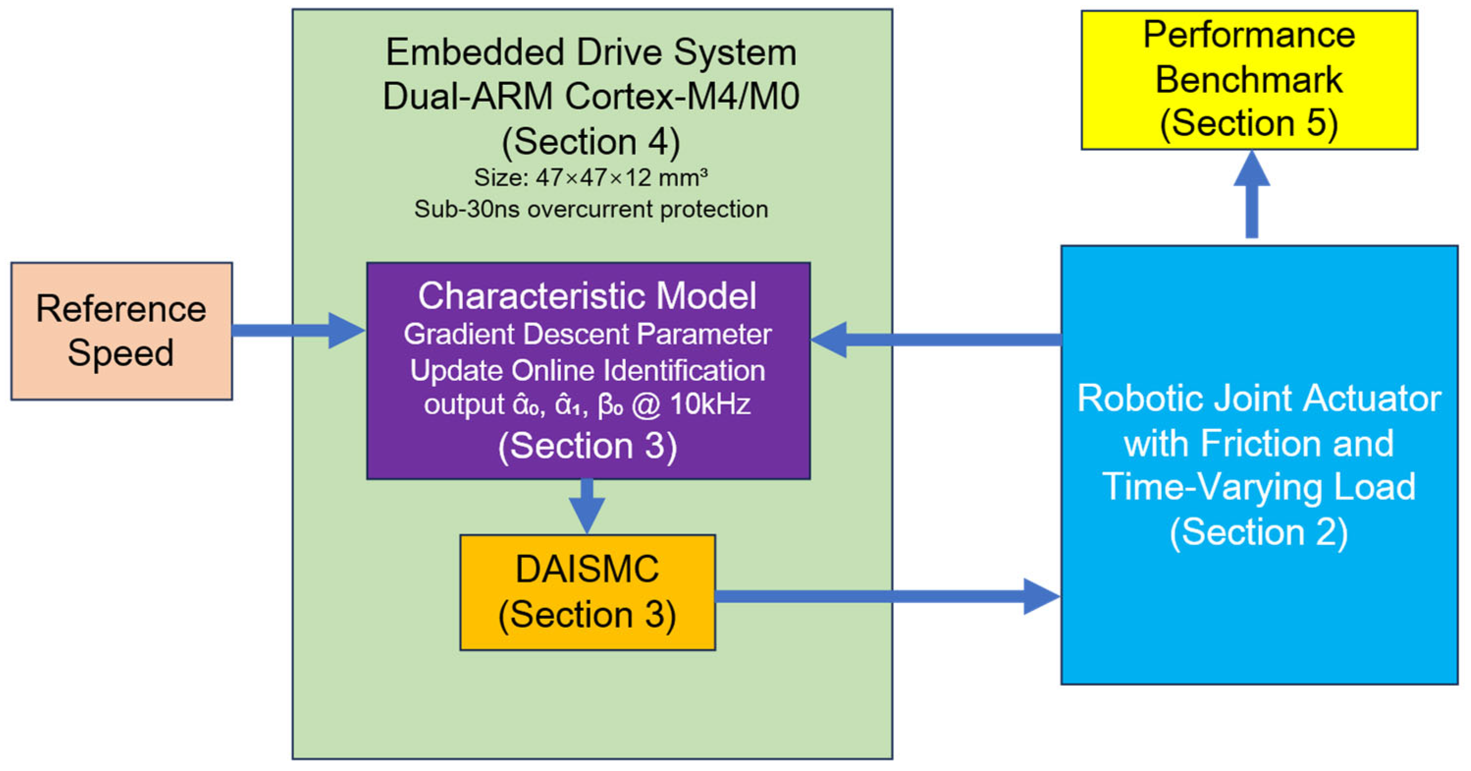
Figure 1. Block diagram of this work.
Symmetry 17 01436 g001
Figure 2. Structural diagram of joint motor.
Symmetry 17 01436 g002
Figure 3. Characteristic modeling simulation: (a) model output, (b) model coefficients, (c) modeling error.
Symmetry 17 01436 g003
Figure 4. Control structure of the system.
Symmetry 17 01436 g004
Figure 5. Structure of the DAISMC.
Symmetry 17 01436 g005
Figure 6. System response simulation under varying γ 0 : (a) speed response at γ 0 = 0.0005, (b) speed response at γ 0 = 0.001, (c) speed response at γ 0 = 0.002, (d) coefficients estimation at γ 0 = 0.0005, (e) coefficients estimation at γ 0 = 0.001, (f) coefficients estimation at γ 0 = 0.002, (g) speed error at γ 0 = 0.0005, (h) speed error at γ 0 = 0.001, (i) speed error at γ 0 = 0.002.
Symmetry 17 01436 g006
Figure 7. DAISMC simulation under time-varying load conditions: (a) speed response, (b) speed error, (c) controller output.
Symmetry 17 01436 g007
Figure 8. DAISMC simulation under step load change: (a) speed response, (b) coefficients estimation, (c) speed error, (d) controller output.
Symmetry 17 01436 g008
Figure 9. Structure of the hardware.
Symmetry 17 01436 g009
Figure 10. Drive and current sensing.
Symmetry 17 01436 g010
Figure 11. DC-link overcurrent protection waveforms.
Symmetry 17 01436 g011
Figure 12. Physical implementation of joint motor drive module: (a) Top view; (b) Bottom view.
Symmetry 17 01436 g012
Figure 13. Flowchart of the proposed control algorithm based on characteristic model.
Symmetry 17 01436 g013
Figure 14. Computational load per algorithm: (a) CPU utilization for DAISMC, (b) CPU utilization for MPC.
Symmetry 17 01436 g014aSymmetry 17 01436 g014b
Figure 15. Experimental platform.
Symmetry 17 01436 g015
Figure 16. Speed response under different ρ : (a) speed response under ρ = 10, (b) speed response under ρ = 30, (c) speed response under ρ = 50, (d) speed response under ρ = 70.
Symmetry 17 01436 g016
Figure 17. Experimental results for step response under no-load conditions: (a) speed response under PI, (b) speed response under CFBSC, (c) speed response under DAISMC, (d) speed error under PI, (e) speed error under CFBSC, (f) speed error under DAISMC, (g) current response under PI, (h) current response under CFBSC, (i) current response under DAISMC.
Symmetry 17 01436 g017
Figure 18. Estimation of characteristic model coefficients and DAISMC output under no-load conditions: (a) estimation of characteristic model coefficients, (b) DAISMC output.
Symmetry 17 01436 g018
Figure 19. On-load testing configuration for joint motor.
Symmetry 17 01436 g019
Figure 20. Schematic diagram of joint motor under on-load operation.
Symmetry 17 01436 g020
Figure 21. Experimental results for step response under loaded conditions: (a) speed response under PI, (b) speed response under CFBSC, (c) speed response under DAISMC, (d) speed error under PI, (e) speed error under CFBSC, (f) speed error under DAISMC, (g) current response under PI, (h) current response under CFBSC, (i) current response under DAISMC.
Symmetry 17 01436 g021
Figure 22. Estimation of characteristic model coefficients and DAISMC output under loaded conditions: (a) estimation of characteristic model coefficients, (b) DAISMC output.
Symmetry 17 01436 g022
Table 1. Parameters of the Simulation.
ParametersValueParametersValue
R 0.24 Ω ω s 0.05   r a d / s
L 0.18   m H λ 0.3   N · m
φ m 0.0224   V · s σ 0 10,000   N · m / r a d
J 0.000323   k g · m 2 σ 1 35   N · m
n p 14 σ 2 0.2   N · m / rad · s 1
F C 0.2   N · m γ 0 0.001
F S 0.25   N · m
Table 2. Parameters of the Joint Motor.
Motor ParametersUnitsValue
Rated Voltage V 24
Rated Torque N · m 5
Rated Speed r p m 120
Rated Current A 10.5
Rated Power W 120
Pole Pairs-14
Torque Coefficient N · m / A 0.47
Line ResistantΩ0.48
Line Inductance m H 0.368
Rotor Mass g 388
Reduction Ratio 8:1
Table 3. Performance Metrics Under Different ρ .
ParameterSAME (rad/s)SRMSE (rad/s)
ρ = 103.110.82
ρ = 302.850.74
ρ = 502.640.76
ρ = 702.630.81
Table 4. Step Response Performance Metrics Under No-load Conditions.
ControllerSettling Time (s)Over Shoot (%)SAME (rad/s)SRMSE (rad/s)
PI0.00720.13%0.910.31
CFBSC0.0055.64%0.680.22
DAISMC0.0054.21%0.720.24
Table 5. Step Response Performance Metrics Under Loaded Conditions.
ControllerSettling Time (s)Over Shoot (%)SAME (rad/s)SRMSE (rad/s)
PI0.00712.39%1.730.42
CFBSC0.0054.85%1.120.31
DAISMC0.0053.93%0.750.25
Disclaimer/Publisher’s Note: The statements, opinions and data contained in all publications are solely those of the individual author(s) and contributor(s) and not of MDPI and/or the editor(s). MDPI and/or the editor(s) disclaim responsibility for any injury to people or property resulting from any ideas, methods, instructions or products referred to in the content.