Article

Algorithm to Find and Analyze All Configurations of Four-Bar Linkages with Different Geometric Loci Degenerate Forms

Department of Civil and Mechanical Engineering (DiCEM), University of Cassino and Southern Lazio, Via G. Di Biasio 43, 03043 Cassino, FR, Italy
*
Author to whom correspondence should be addressed.
Symmetry 2025, 17(8), 1171; https://doi.org/10.3390/sym17081171
Submission received: 29 May 2025 / Revised: 24 June 2025 / Accepted: 10 July 2025 / Published: 22 July 2025

Abstract

A general algorithm to determine the coupler link geometric loci, such as centrodes, inflection and return circles, as well as circling-point and centering-point curves, is formulated to analyze any type of four-bar linkages with the main target to find all mechanism configurations, in which at least one of the above-mentioned loci degenerates. Thus, different types of four-bar linkages, such as crank-rocker, double-crank, double-rocker and triple-rocker, are classified according to Grashof’s law, in order to distinguish and analyze their corresponding geometric loci. In particular, the proposed algorithm is based on four diagrams of the angular velocity ratios versus the mechanism driving angle, which consider the links pairs of input/output, input/coupler, and output/coupler, along with those of coupler/input and coupler/output for their relative motion. These diagrams allow the determination of all mechanism configurations according to Freudenstein’s theorems, where the aforementioned geometric loci degenerate into straight lines, including the line at infinity, ϕ-curves, and/or equilateral hyperbolas. This algorithm has been implemented in Matlab in order to run several examples regarding different four-bar linkages, according to Grashof’s law, and analyzing the degenerate forms of their inflection and return circles, as well as the circling-point and centering-point curves, that are also validated by using the collineation axis.

1. Introduction

Four-bar linkages represent one of the most widely studied planar mechanical systems due to their simplicity, versatility, and relevance in motion generation and control. Their structure, consisting of four rigid bodies connected by four revolute joints, forms the foundation of many motion-generating mechanisms used in robotics, industrial automation, and biomechanical devices. The analysis of such systems relies heavily on the geometric and algebraic relationships among the link parameters and their relative motions, with a particular focus on configurations that lead to critical kinematic behaviors. Among the analytical key tools for understanding 4R linkages, there are the classical theorems introduced by Freudenstein, which formalize the input–output angular relationships and provide a systematic basis for evaluating velocity and acceleration characteristics. In particular, the work in [1] established geometrical criteria to detect maximum and minimum angular velocity ratios and compute accelerations in specific configurations, laying the foundation for velocity-based mechanism design. A reformulation of these theorems using vector loop equations was proposed in [2], where the authors demonstrated how different analytical forms could be used to identify phases of extreme motion while also clarifying the limitations in locating exact configuration values. The formal structure of Freudenstein’s relationships has been the subject of further refinement, including purely vectorial derivations [3], which reinforce their algebraic transparency and value. More recently, in [4] is a differential algebraic framework that extends the traditional formulation to higher-order derivatives of input–output equations, enabling the evaluation of signed velocity ratios and acceleration conditions across six possible angular configurations, is proposed. This approach not only enriches the interpretation of Freudenstein’s results but also connects them to more advanced studies on force transmission and dynamic response. In parallel, the geometric implications of Freudenstein-like conditions have been explored in [5], where the authors investigated symmetrical coupler curves designed to approximate straight-line paths. By exploiting the collinearity of Burmester points, they demonstrated how certain degenerate conditions can be purposefully designed using extended Freudenstein-based criteria.
While the classical kinematic framework offers a solid basis for analyzing general motion in 4R mechanisms, particular attention must be given to those configurations in which the behavior of the system becomes critical or degenerate. These configurations, typically referred to as singularities or asymptotic configurations, are of great importance in both theoretical analysis and practical design, as they often correspond to sudden changes in mobility, loss of control, or degeneration of characteristic geometric loci. Understanding and predicting such behaviors is therefore essential when aiming for reliable and robust mechanical performance. One early contribution to this area is the graphical method proposed in [6], which simplifies the acceleration analysis of four-bar linkages without relying on velocity or acceleration polygons, providing a faster and more intuitive assessment of follower behavior near critical configurations. Degenerate forms of specific geometric loci were studied in [7], where a four-bar linkage was used to drive a Geneva wheel with jerk-free motion. Here, the authors observed how the coupler-point path could collapse into symmetrical forms, depending on the linkage parameters. A more systematic classification of such degeneracies was later developed in [8], where conditions for the degeneration of circling-point and centering-point curves were established analytically, and presented in a compact tabular format. The higher-order analysis of such phenomena has been extended through screw theory and curvature methods. In [9], the authors presented a framework for evaluating the stationary curvature properties of four-bar mechanisms using derivatives of screws, revealing how classical loci such as the cubic of stationary curvature behave in translational and rotational configurations. Furthermore, they showed that traditional coordinate-based methods fail in certain geometries, such as parallelogram linkages, which can instead be treated effectively using screw-based tools. Similarly, in [10], screw system algebra is applied to analyze uncertainty configurations, extending these techniques to both planar and spatial chains, and demonstrating their applicability to the detection of limiting behavior in higher-degree mechanisms. Analytical insights into singular configurations were also offered in [11], where the authors categorized the singularities of closed-loop kinematic chains through the properties of the Jacobian matrices, providing a classification that is widely applicable to both linkages and parallel robots. Geometric consequences of these singularities were further explored in [12], which examined the behavior of coupler-point paths and line envelopes as the instantaneous center approaches infinity, revealing characteristic degenerations in the inflection and cusp circles. A complementary approach was presented in [13], which introduced improved definitions for circuits and branches in planar mechanisms and emphasized how topological ambiguities may conceal degenerate conditions. More complex configurations were examined in [14], where double configurations in Assur kinematic chains and stationary states in Stephenson six-bar linkages were analyzed through the gradient of the coupler curve and its relation to dismantled binary links. Several studies have focused specifically on dead-center positions, where the mechanism temporarily loses mobility. The modular analysis method proposed in [15] uses Assur kinematic chains to identify these positions based on the gain of mobility in substructures. A related polynomial-based method was introduced in [16], which formulates necessary conditions for dead-center states in Stephenson six-bar linkages using Sturm functions and input–output equations. Earlier treatments of this problem include [17,18], which applied instant center methods and kinematic inversion to map all possible stationary configurations in six-bar planar mechanisms. The consequences of such configurations on practical mechanism design are non-trivial. For instance, in [19], the instantaneous motion of a line in asymptotic positions was investigated, showing how centrodes behave near an infinite pole and how line-envelope contact points change their nature in such cases. These results highlight the need to consider higher-order effects when approaching degeneracies. Recent contributions have also integrated these concepts into kinematic synthesis procedures. In [20], the authors proposed a method for generating Stephenson III six-bar mechanisms with instantaneous stop in the coupler link, combining a crank-driven, four-bar sub-chain with a ternary coupler link specifically configured to exhibit an instantaneous stop. In [21], the same class of mechanisms was studied in terms of first- and second-order centrodes, with particular attention to cases where the coupler exhibits an instantaneous stop and/or a simple dwell. The study of geometric loci in planar mechanisms represents a key aspect of kinematic analysis and synthesis. These loci are crucial for understanding the qualitative behavior of mechanisms and for guiding the design, for example, of paths with desired curvature, shape, or functional properties. Among the most significant loci are the centrodes, the inflection circle, the return circle, the cubic of stationary curvature, and the circling-point and centering-point curves. Their characterization provides essential insights into transmission efficiency, instantaneous kinematic properties, and critical configurations. The synthesis of mechanisms aimed at producing quasi-constant transmission ratios often relies on the precise control of such loci. In [22], closed-form algorithms were developed to design planar linkages, both four-bar and slider–crank types, with prescribed curvature behavior. By combining centrode analysis, inflection circles, and the Euler–Savary equation, the authors demonstrated how to obtain consistent motion profiles across infinitesimal and finite displacements. An example of kinematic modeling and synthesis applied to more complex mechanical systems can be found in [23], where an eight-bar mechanism was proposed for an upper-limb exoskeleton aimed at assisting elbow joint motion during repetitive heavy-lifting tasks [23]. The nature of higher-order loci was further investigated in [24], where algorithms for computing first-, second-, and third-order centrodes as well as Bresse’s circles were proposed. These allow for the visualization of instantaneous centers of rotation, acceleration, and jerk across a wide range of configurations, showing how such higher-order information can inform mechanism design at a deeper level. Other geometric curves with relevance to planar kinematics have also been explored. In [25], the mathematical properties of strophoids were discussed in detail. These curves emerge naturally as projections of circle-point curves, and exhibit numerous geometric symmetries and involutions, which can be exploited in the design of mechanisms with stationary curvature features. Foundational treatments of motion geometry can be found in classic texts such as [26,27], which provide comprehensive formulations of linkage motion and coupler curve generation. These works laid the groundwork for later developments in the synthesis and classification of mechanism behavior. Similarly, ref. [28] offers a modern reinterpretation of curvature theory in planar motion, with a particular emphasis on instantaneous invariants and their role in guiding motion synthesis. Other key references that consolidate the theoretical basis of geometric loci analysis include [29], where the Carter-Hall circle is defined via velocity diagrams and used for the synthesis of fifth-order function generators, and [30], which presents a geometric method to coordinate coupler-point positions and crank rotations based on Roberts’ configuration. The synthesis of paths with desired directionality and timing is addressed through Burmester curves and degenerate forms of coupler motion. Comprehensive introductions to these concepts are also provided in classical textbooks such as [31,32,33,34], which collectively address the geometry of planar mechanisms, the kinematic synthesis of linkages, and the role of curvature and centrodes in practical design scenarios. Complementary to the analytical and geometric methods discussed above, recent studies in the field of robotics have explored the use of intelligent and adaptive strategies to deal with critical configurations and motion planning in complex environments. Such approaches often rely on evolutionary algorithms and data-driven models to enhance system robustness under degenerate or uncertain conditions [35,36].
In this paper, a general algorithm to find and analyze all configurations of four-bar linkages with different geometric loci degenerate forms, is proposed. In fact, as reported above, in the state-of-the-art analysis, there is not any scientific paper dealing with this specific topic, as the simplification of the design process of path generators and dwell mechanisms. In particular, different types of four-bar linkages are classified according to Grashof’s law, while four diagrams of the angular–velocity ratios versus the mechanism driving angle are determined to identify, in agreement with Freudenstein’s theorems, the four-bar linkages configurations, where the above-mentioned geometric loci degenerate into straight lines, including the line at infinity, ϕ-curves, and/or equilateral hyperbolas. This algorithm has been implemented in Matlab and validated by using the collineation axis and several significant examples.

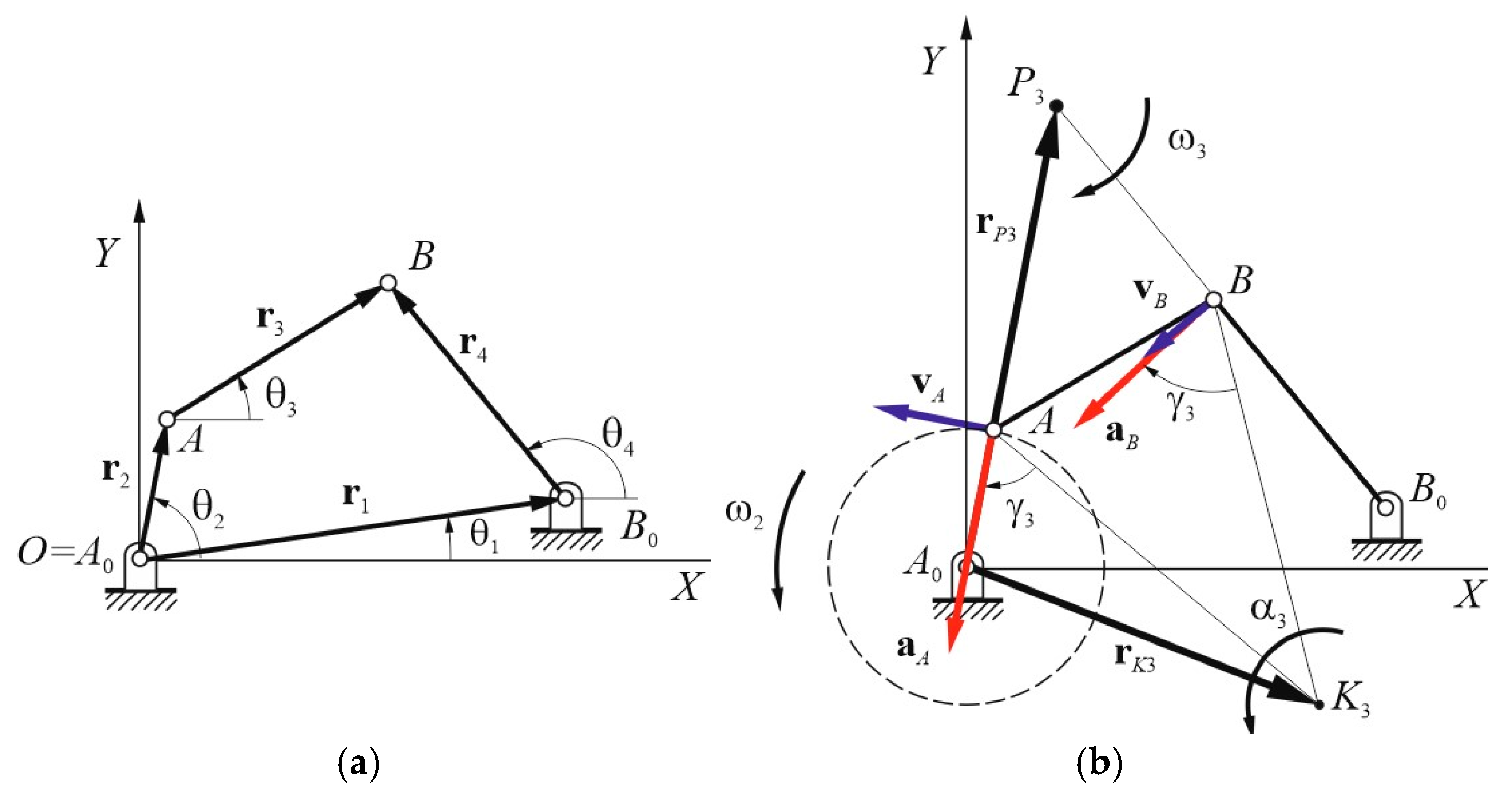
2. Kinematic Analysis: Velocity and Acceleration Poles

This section deals with the kinematic analysis of four-bar mechanisms, focusing on Grashof’s law, different inversions, and position analysis.
Grashof’s law determines the rotational behavior of linkages in a planar four-bar mechanism. It states that, for a continuous relative rotation between two elements, the sum of the lengths of the shortest link s and the longest link l must be less than or equal to the sum of the lengths of the other two links, p and q. This is expressed as
s + l p + q
A four-bar chain that satisfies the Grashof inequality is referred to as a Grashof chain. In such a mechanism, the shortest link s is always capable of continuous rotation relative to the other three links. The type of motion produced by a Grashof chain depends on which link is fixed. If the link adjacent to the shortest link is fixed, the mechanism functions as a crank-rocker, where the s acts as the crank and rotates continuously, while its opposite link oscillates and serves as the rocker. When the s itself is fixed, the mechanism becomes a double-crank linkage, allowing both adjacent links to fully rotate, with the shorter of the two typically designated as the input crank. Alternatively, if the link opposite to the shortest one is fixed, the mechanism becomes a double-rocker, in which neither of the adjacent links can complete a full rotation, and both merely oscillate. If the Grashof inequality is not satisfied, the mechanism is classified as a non-Grashof chain. In this case, no single link is capable of a complete revolution regardless of which link is fixed. The only possible inversion in a non-Grashof configuration is the triple-rocker mechanism, where all three moving links are restricted to oscillatory motion.
Referring to the kinematic sketch of Figure 1, the position analysis of a generic four-bar mechanism can be determined through the following loop-closure equation:
r 2 + r 3 = r 1 + r 4
where ri represents the position vector for link i (for i = 1, …, 4). These position vectors can be expressed in vector form with respect to the fixed frame OXY, as follows:
r i = r i c o s θ i i + s i n θ i j
where ri denotes the magnitude and θi represents the counterclockwise-oriented angle of position vector ri. Specifically, θ2 represents the driving angle of the input link 2. For the fixed link 1, r1 and θ1 are constant values representing the magnitude and orientation from point A0 to B0, respectively. The position vectors for specific points, such as rA and rB of points A and B, can also be expressed as
r A = r 2 r B = r 1 + r 4
Referring to the scheme of Figure 1a, the angular position θ3 of coupler link AB can be evaluated by developing Equation (2), as follows:
θ 3 = tan 1 r 1 sin θ 1 r 2 sin θ 2 + r 4 sin θ 4 r 1 cos θ 1 r 2 cos θ 2 + r 4 cos θ 4
The angular position θ4 of link B0B can be expressed as
θ 4 = 2 t a n 1 + σ 2 C 2 + 𝒜 2 C 𝒜
where σ is equal to ±1 according to a suitable assembly mode and the parameters:
𝒜 = 2 r 1 r 4 cos θ 1 2 r 2 r 4 cos θ 2 = 2 r 1 r 4 s i n θ 1 2 r 2 r 4 sin θ 2 C = r 1 2 + r 2 2 + r 4 2 r 3 2 2 r 1 r 2 cos θ 1 θ 2
By the first-time derivatives of Equation (2), one has the angular velocity vectors ω3 and ω4
ω 3 = θ ˙ 3   k = ω 2 r 2 r 3 sin θ 2 θ 4 sin θ 4 θ 3 k
ω 4 = θ ˙ 4   k = r 2 ω 2 r 4 sin θ 2 θ 3 sin θ 4 θ 3 k
where ω2 represents the angular velocity magnitude of the input link 2.
The second-time derivatives of Equation (2) yield the angular acceleration α3 and α4 as
α 3 = θ ¨ 3   k = r 2 α 2   s i n θ 2 θ 4 + r 2 ω 2 2 c o s θ 2 θ 4 + r 3 ω 3 2 c o s θ 3 θ 4 r 4 ω 4 2 r 3   s i n θ 4 θ 3 k
α 4 = θ ¨ 4   k = r 2 α 2   s i n θ 2 θ 3 + r 2 ω 2 2 c o s θ 2 θ 3 + r 3 ω 3 2 r 4 ω 4 2 c o s θ 4 θ 3 r 4   s i n θ 4 θ 3 k
where α2 represents the angular acceleration of input link 2.
Referring to the scheme of Figure 1b, the velocity vectors vA, vB, and vP3 of points A, B, and P3 can be expressed as
v A = r ˙ 2 = ω 2 r 2 sin θ 2 i + ω 2 r 2 cos θ 2 j
v B = r ˙ 4 = r ˙ 2 + ω 3 × r 4 r 2
v P 3 = r ˙ P 3 = r ˙ 2 + ω 3 × r P 3 r 2
where rP3 is the position vector of the velocity pole P3 that can be obtained by Equation (14) by imposing vP3 = 0, and thus, one has
r P 3 = r ˙ 2 y ω 3 + r 2 x i + r ˙ 2 x ω 3 + r 2 y j
Similarly, the acceleration vectors aA, aB, and aK3 of points A, B, and K3, respectively, in agreement with the Rivals theorem, take the following expressions:
a A = r ¨ 2 = ω 2 2 r 2 cos θ 2 α 2 r 2 sin θ 2 i + ω 2 2 r 2 sin θ 2 + α 2 r 2 cos θ 2 j
a B = r ¨ 4 = r ¨ 2 + α 3 × r 4 r 2 + ω 3 × ω 3 × r 4 r 2
a K 3 = r ¨ K 3 = r ¨ 2 + α 3 × r K 3 r 2 + ω 3 × ω 3 × r K 3 r 2
where rK3 is the position vector of the acceleration pole K3 that can be derived by Equation (18) for aK3 = 0, and thus, one has
r K 3 = ω 3 2 r ¨ 2 x α 3 r ¨ 2 y ω 3 4 + α 3 2 + r 2 x i + α 3 r ¨ 2 x + ω 3 2 r ¨ 2 y ω 3 4 + α 3 2 + r 2 y j
Therefore, the position vectors rP3 and rK3 of the velocity P3 and acceleration K3 poles are given by Equations (15) and (19), respectively, while the corresponding angular velocity ω3 and acceleration α3 vectors are given by Equations (8) and (10).

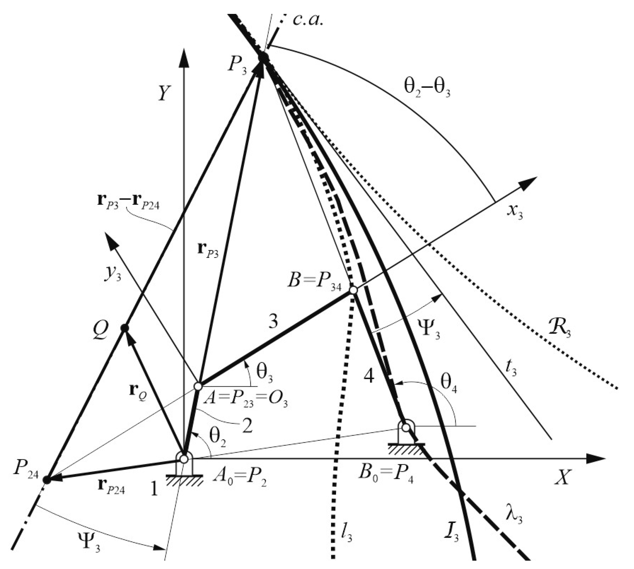
3. Collineation Axis

Referring to Figure 2, Bobillier’s theorem for the four-bar linkage A0ABB0 states what follows: the counterclockwise angle ψ3, which is made by the collineation axis c.a. joining the instant centers (ICs) P3 and P24 with the rotating link A0A, is equal to the same oriented angle that is made by rotating link B0B with the pole tangent t3.
This theorem is strictly connected to the Aronhold–Kennedy theorem, which allows the determination of all ICs of a mechanism, along with, in particular, the obtaining of P2 = A0, P23 = A, P4 = B0, and P34 = B by the kinematic properties of the revolute joints. Consequently, P24 and P3 are, respectively, given by the intersections between of the two straight lines passing through the ICs P2P4 and P23P34, and likewise through P2P23 and P4P34.
Thus, the corresponding equations of these straight lines with respect to the fixed frame OXY can be obtained as follows:
y r 2 y = m 1 x r 2 x y y A 0 = m 2 x x A 0
m 1 = r 2 y r 4 y r 2 x r 4 x m 2 = y A 0 y B 0 x A 0 x B 0
where ( x A 0 , y A 0 ), ( x B 0 , y B 0 ), ( r 2 x , r 2 y ), and ( r 4 x , r 4 y ) are the Cartesian coordinates of points A0, B0, A, and B, respectively. Therefore, by developing Equations (20) and (21), the position vector r P 24 of P24 in Cartesian form with respect to OXY is given by
r P 24 = 1 m 2 m 1   y A 0 r 2 y m 2 x A 0 + m 1 r 2 x i + m 1 y A 0 m 2 r 2 y + m 1 m 2 r 2 x x A 0 j
Consequently, the collineation axis c.a. can be expressed as follows:
r P 3 r P 24 × r Q r P 24 = 0
where r Q is the position vector of point Q, which is a generic point of the c.a.
By developing Equation (23) and simplifying it in Cartesian form, one has
y = r P 24 y r P 3 y r P 24 x r P 3 x x r P 24 x + r P 24 y
where ( r P 3 x , r P 3 y ) and ( r P 24 x , r P 24 y ) are the Cartesian components of r P 3 and r P 24 .
In a four-bar linkage, Freudenstein’s Theorem 1 states that when the input–output velocity ratio is stationary, the c.a. is perpendicular to the coupler link AB (or r3). This configuration is shown in Figure 3a, where links 2 and 4 serve as the input and output, respectively. The angular velocity ratio τ24 can be expressed in the form
τ 24 = ω 4 ω 2
where ω4 is expressed by Equation (9) and ω2 is the input angular velocity of the mechanism. Two significant scenarios arise from Equation (25).
In particular, when τ24 equals zero, this implies that ω4 is also zero. In this case, IC P3 coincides with point B, and point A0 with P24. Consequently, the c.a. aligns with the coupler link AB.
When τ24 equals 1, this implies that ω4 is equal to ω2. Thus, point P24 tends towards infinity because ω24 becomes zero. As a result, the c.a. becomes parallel to both the coupler link AB and the fixed link A0B0 (or r1).
Freudenstein’s Theorem 2 states that at a stationary value of the angular velocity ratio between the coupler and one of the frame-adjacent links, the c.a. is perpendicular to the opposite frame-adjacent link. Figure 3b illustrates a configuration where links 2 and 3 are the input and output links, respectively. The angular velocity ratio τ23 is given by
τ 23 = ω 3 ω 2
where ω3 is expressed by Equation (8). Figure 3c shows another configuration with links 4 and 3 as the input and output links, respectively. One has the angular velocity ratio τ43
τ 43 = ω 3 ω 4
By considering Equations (26) and (27), significant conditions can be obtained. In particular, when both τ23 and τ43 equal zero, this implies that ω3 is also zero. In this specific kinematic configuration, point P3 tends to infinity, and the c.a. becomes parallel to both the input link A0A and the output link B0B. When τ23 equals 1, it means that ω3 is equal to ω2. In this situation, point P24 coincides with point B, and point A0 with P3. Consequently, the c.a. aligns with the fixed link A0B0. When τ43 equals 1, it implies that ω3 is equal to ω4. In this case, point P24 coincides with point A, and point B0 with P3. Similarly to the previous scenario, the c.a. also aligns with the fixed link A0B0.
Freudenstein’s Theorem 3 states that at a stationary value of the relative angular velocities between the coupler link and each of the frame-adjacent links, specifically ω32 and ω34, the c.a. is perpendicular to the line of centers A0B0. Figure 3d shows such a configuration of a four-bar linkage. The relative angular velocity ratio τR can be expressed as follows:
τ R = ω 3 ω 2 ω 3 ω 4 = ω 32 ω 34
Two significant conditions can be deduced from Equation (28). In particular, when τR equals zero, this implies that ω3 is equal to ω2. This condition is equivalent to the case of τ23 equals 1, as described in Freudenstein’s Theorem 2, where the c.a. aligns with the fixed link A0B0. When τR equals 1, this implies that ω4 is equal to ω2. This corresponds to the condition of τ24 equals 1 in Freudenstein’s Theorem 1, where the c.a. becomes parallel to both the coupler link AB and the fixed link A0B0.

4. Kinematic Analysis: Geometric Loci

Inflection circle I3 is the geometric locus of the coupler points, which shows an inflection point in their paths and is always tangent to both centrodes at the instantaneous center of rotation P3. By considering a generic point M of coupler link AB, the equation of inflection circle I3 can be conveniently obtained by imposing a zero-cross product, as follows:
v M × a M = 0
where M is a generic coupler point of link 3. In particular, vectors v M and a M are obtained by Equations (13) and (17) for B = M and referring to the velocity and acceleration vectors of point A. Thus, substituting ω 3 and α 3 of Equations (8) and (10) into Equations (13) and (17), one has v M and a M in matrix form:
v M = r 2 y ω 3 ω 2 ω 3 y r 2 x ω 2 ω 3 + ω 3 x 0
a M = r 2 x ω 3 2 ω 2 2 + r 2 y α 3 α 2 ω 3 2 x α 3 y r 2 x α 2 α 3 + r 2 y ω 3 2 ω 2 2 + α 3 x ω 3 2 y 0
where r 2 x and r 2 y , along with x and y, are the Cartesian components of r A and r M , respectively. Therefore, substituting Equations (30) and (31) into Equation (29), and developing it, one has the following algebraic equation of the inflection circle I3
r 2 y ω 3 ω 2 ω 3 y r 2 x α 2 α 3 + r 2 y ω 3 2 ω 2 2 + α 3 x ω 3 2 y r 2 x ω 2 ω 3 + ω 3 x r 2 x ω 3 2 ω 2 2 + r 2 y α 3 α 2 ω 3 2 x α 3 y = 0 .
Simplifying Equation (32), one can obtain the following expression:
x 2 + y 2 + 𝒜 I 3 x + I 3 y + C I 3 = 0
where
𝒜 I 3 = r 2 x ω 3 2 ω 2 2 ω 3 3 + ω 2 2 ω 3 + r 2 y ω 3 α 2 ω 2 α 3 ω 3 3 I 3 = r 2 x ω 3 α 2 + ω 2 α 3 + r 2 y ω 3 2 ω 2 2 ω 3 3 + ω 2 2 ω 3 ω 3 3 C I 3 = ω 2 ω 3 r 2 x r 2 x ω 2 2 ω 3 2 + r 2 y α 2 α 3 r 2 y r 2 x α 2 α 3 r 2 y ω 2 2 ω 3 2 ω 3 3
The return circle 3 can be obtained by mirroring the inflection circle I3 with respect to the tangent line t3 at point P3, as seen in Figure 2.
As is well known, the coupler motion can be replaced by the pure-rolling of the moving centrode on the fixed one, which are traced by the corresponding IC. In particular, referring to the coupler link AB of the four-bar linkage A0ABB0 of Figure 2, the IC P3 traces the fixed centrode λ3 on the fixed plane OXY, and likewise the moving centrode l3 on O3x3y3. Thus, λ3 is given by Equation (15), while l3 in O3x3y3, takes the form:
r P 3 * = r 3 sin θ 4 θ 3 sin θ 4 θ 2 cos θ 2 θ 3 , sin θ 2 θ 3 ,   0   T
where symbol T indicates the transpose matrix.
In order to express the moving centrodes l3 of the coupler link 3 with respect to the fixed frame OXY, the vector function of Equation (35) takes the form:
r = T r P 3 *
where T is the following homogeneous transformation matrix by O3x3y3 to OXY as follows:
T = cos θ 3 sin θ 3 x O 3 sin θ 3 cos θ 3 y O 3 0 0 1
Particular points on the moving plane have a stationary curvature, i.e., the rate of change in their curvature radius with respect to reference position is zero.
Referring to Figure 4 and to study the trajectories of the coupler points, the canonical reference frame having its origin in P3, the x-axis along the pole being tangent T3 to both centrodes l3 and λ3, and the y-axis coinciding with the corresponding normal N3 in P3 that is oriented toward the center OI3 of the inflection circle I3, are conveniently introduced.
The circling-point curve ku, also known as cubic of stationary curvature, is the locus of all coupler points whose paths have at least four contact points with their osculating circles, thus having a stationary curvature. This geometric locus is represented by a third-order algebraic curve that is named strophoid and denoted as α-curve.
In particular, points A and B of the generic four-bar linkage A0ABB0 of Figure 4 have a stationary curvature, since their paths are circles of centers A0 and B0, respectively.
The equation of the ku curve can be expressed in polar form as follows:
1 h = 1 M   s i n Ψ + 1 N   c o s Ψ
where the coefficients M and N are the instantaneous geometric invariants, h is the oriented segment defining the position of a generic coupler point P, and Ψ is the corresponding clockwise oriented angle with respect to N3-axis of the P3T3N3 canonical frame.
The coefficients M and N can be determined by substituting the polar coordinates h A , Ψ A and h B , Ψ B of points A and B of ku in Equation (35), thus obtaining
1 h A = 1 M   s i n Ψ A + 1 N   c o s Ψ A
1 h B = 1 M   s i n Ψ B + 1 N   c o s Ψ B
which can be solved to achieve M and N in the following form:
M = h A h B s i n Ψ A Ψ B s i n Ψ A sin Ψ B h A c o s Ψ B h B c o s Ψ A
N = h A h B s i n Ψ A Ψ B c o s Ψ A cos Ψ B h A s i n Ψ B h B s i n Ψ A
The equation of the ku curve can also be expressed in Cartesian form as follows:
ν 2 + μ 2 ν M + μ N ν μ = 0
where ν and μ are given by
ν = y r P 3 y + x r P 3 x tan β tan β sin β + cos β
μ = x r P 3 x + ν sin β cos β
where β is the counterclockwise-oriented angle made by the abscissa T3-axis of the canonical frame, with respect to the x-axis of OXY, as shown in Figure 4.
The locus of the centers of curvature of all points lying on ku is still a circular cubic, also known as centering-point curve ka, which can be expressed by
Γ 2 + Π 2 Γ M ¯ + Π N ¯ Γ   Π = 0
where
Γ = y r P 3 y + x r P 3 x tan β tan β sin β + cos β
Π = x r P 3 x Γ sin β cos β
1 N ¯ = 1 δ + 1 N N ¯ = δ N δ N
1 M ¯ = 1 M M ¯ = M
where δ is the diameter of the inflection circle I3.
In general, both the ku and ka curves are strophoids (or α-curves), as observed in Figure 4. The intersection of the ku curve and the infection circle I3 defines Ball’s point, which is a point in the moving plane that describes a straight line with a third-order approximation or more. All points on the ku curve have a stationary curvature and those lying on the inflection circle show an inflection point of their paths. Thus, Ball’s point is the intersecting point of the cubic of stationary curvature ku and the inflection circle I3.
The IC P3 gives information about the velocities of all coupler points, and the inflection circle I3 provides information about those with zero acceleration (or infinite radius of curvature). Instead, the ku curve refers to the third-order properties of motion, particularly when the radius of curvature of a point’s path is momentarily constant. It is often used in mechanism synthesis, particularly for path generation, where a coupler point is required to follow a specific path, with certain curvature properties.
The degeneration of the ku curve and its corresponding ka curve is a specialized concept in kinematics that describes when this higher-order curve, which determines points of stationary curvature, simplifies into more basic geometric forms, like a circle and a line. This simplification is not random; it is a consequence of specific kinematic configurations of the mechanism and often corresponds to points with particularly desirable or unique path properties, making it relevant for mechanism synthesis and analysis.
In general, the ku and ka curves can degenerate into the following: a circle and a straight line or into a ϕ-curve; multiple lines; in some cases, it might even degenerate into three lines, which might include the line at infinity; and an equilateral hyperbola together with the straight line at infinity. This paper highlights how the angular velocity ratios (τ24, τ23, τ43, and τR) are central parameters for understanding the kinematic behavior of a mechanism. By carefully observing these ratios and their derivatives, one can discover specific configurations, including singular or maximum/minimum positions, that lead to the simplification of complex ku and ka curves, which are extremely useful for mechanism design and analysis. In a four-bar linkage, specific configurations lead to extreme velocity ratios and characteristic behaviors of the inflection circle’s diameter and the c.a.
When a mechanism reaches configurations with extreme velocity ratios (τ24, τ23, τ43 and τR), the inflection circle’s diameter remains stationary. This occurs when each of the links (r3, r4, r2, and r1) forms a 90° angle with the c.a., as detailed in Section 3.
The angular velocity ratios, τ24, τ23, τ43, and τR, can be plotted against the corresponding input angle θ2 for the four-bar linkage, as shown in Figure 5. This plot helps to identify four values for each ratio: their maximum and minimum values, and when they equal 0 and 1. When τ24 is at its minimum or maximum values, as seen in Figure 6a, the c.a. becomes orthogonal to the coupler link AB. In this state, the ku curve degenerates into a ϕ-curve, which is a circle passing through the points A, B, and P3. It also forms a straight line that coincides with the tangent t3 to the inflection circle I3 at the IC P3. In the case where τ23 is at its minimum or maximum values, as seen in Figure 6b, the c.a. becomes orthogonal to the output link B0B. In this configuration, both the ku and ka curves degenerate into ϕ-curves. This results in the following: a circle passing through points A and P3; another circle passing through points B0 and P3; a straight line that passes through points A0 and A, coinciding with the tangent t3 to the inflection circle I3 at point P3. A special case can be obtained when τ24 is at its minimum or maximum values, as seen in Figure 6c: The c.a. becomes parallel to both the input link A0A and the output link B0B, and it also becomes perpendicular to the coupler link AB. In this specific configuration, point P3 tends to infinity. This causes the ka curve to degenerate into an equilateral hyperbola that passes through the points A0, A, and P3 (at infinity), including the line at infinity. Simultaneously, the ku curve degenerates into two straight lines: one passing through points A and B, and the other parallel to P3, along with a line at infinity.

5. Numerical Examples

To validate the general algorithm for the synthesis of four-bar mechanisms, it was implemented in Matlab (2018b) and tested through several significant examples. As shown in Figure 7, a flowchart of the proposed algorithm is provided to enhance clarity and reproducibility, illustrating the sequence of calculations and referencing the relevant equations. Table 1 details the dimensions of these mechanisms, all with an angular velocity ω2 of 1 r/s. The examples include Cases 1–3 as crank-rocker mechanisms, Case 4 as a double-crank, Case 5 as a double-rocker, and Case 6 as a triple-rocker.
Case 1: A crank-rocker mechanism is analyzed in detail, with its results shown in Figure 8, Figure 9, Figure 10, Figure 11 and Figure 12 and Table 2. Referring to Figure 8, the diagrams of the velocity ratios τ24, τ23, τ43, and τR are analyzed as functions of the input angle θ2 and thus, they are represented in Figure 8a, b, c, and d, respectively. Particular attention is given to the maximum and minimum values of these ratios, as well as where they equal 0 or 1. A key aspect of the study is the correlation between these velocity ratios, the c.a., and the degeneration of ku and ka curves into special curves. This detailed examination of Case 1 offers valuable insights into the kinematic behavior of crank-rocker mechanisms, specifically regarding the transmission angle, other velocity ratios, and the geometric properties of their associated curves at critical configurations. In addition, each figure illustrating a case study includes a legend that clearly distinguishes the following geometric loci: the fixed centrode λ3 (blue, dot line), the moving centrode l3 (cyan, dot line), the inflection circle I3 (green, solid line), the return circle 3 (green, dotted line), the ku curve (magenta dark, dotted line), the ka curve (magenta light, dotted line), and the collineation axis c.a. shown in red with a dash-dotted line. For velocity ratio τ24, the specific results of Case 1 are as follows:
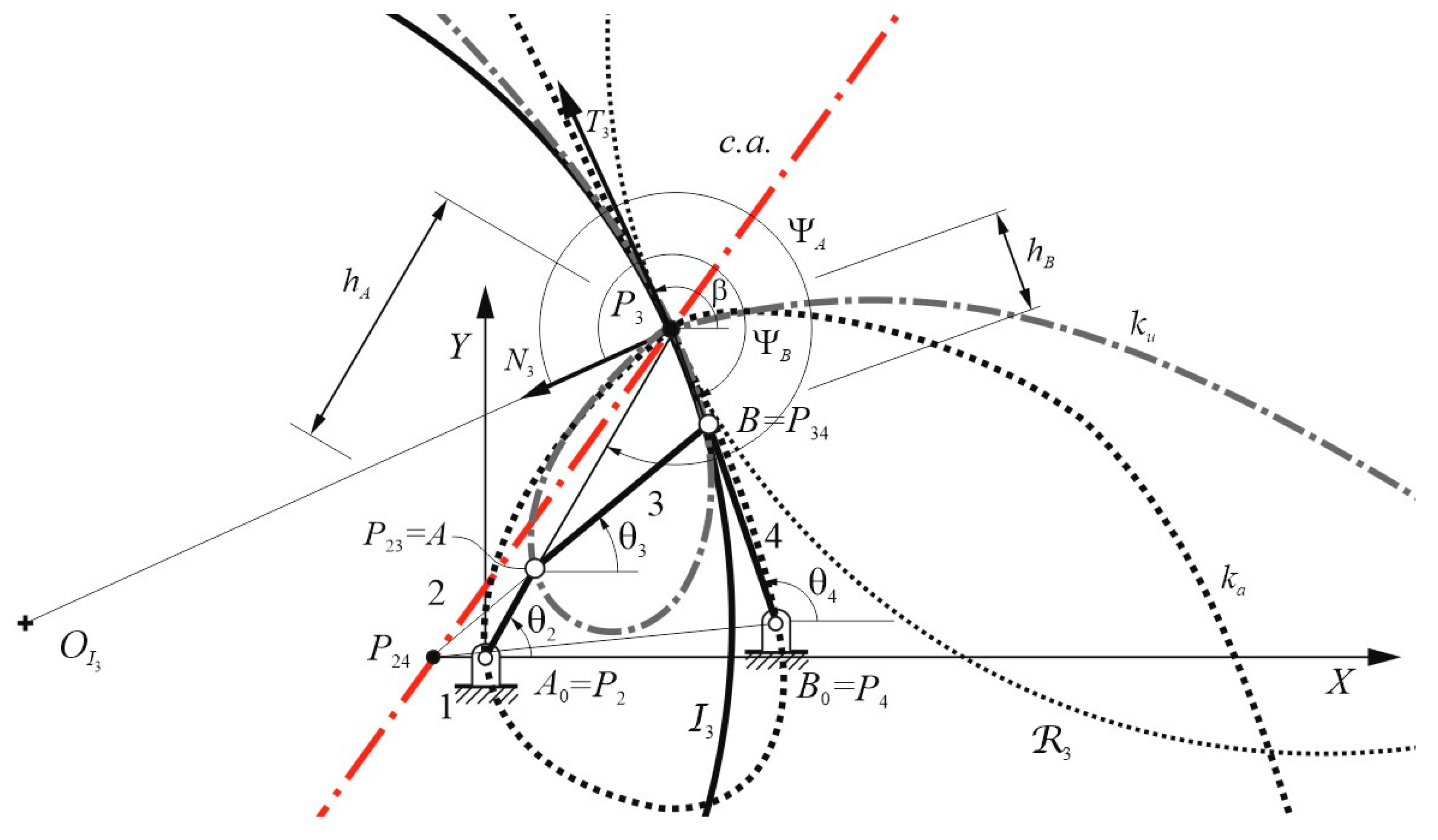
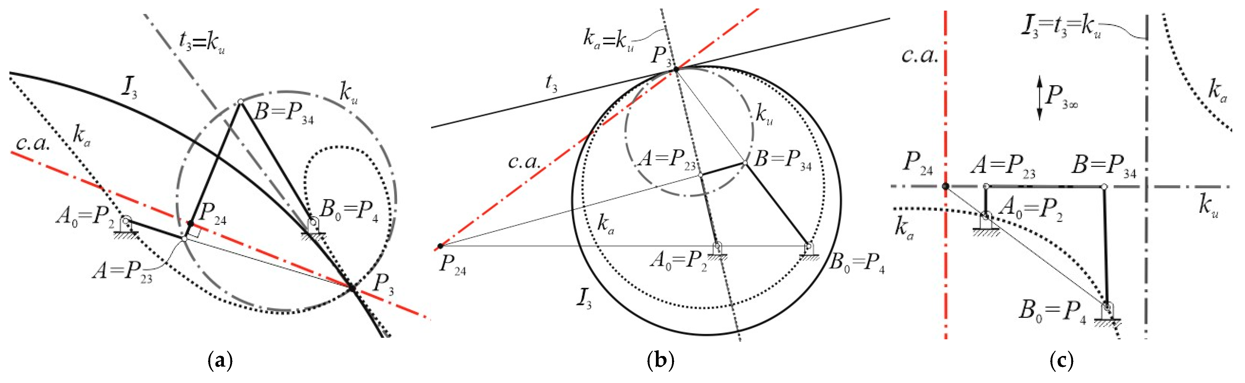
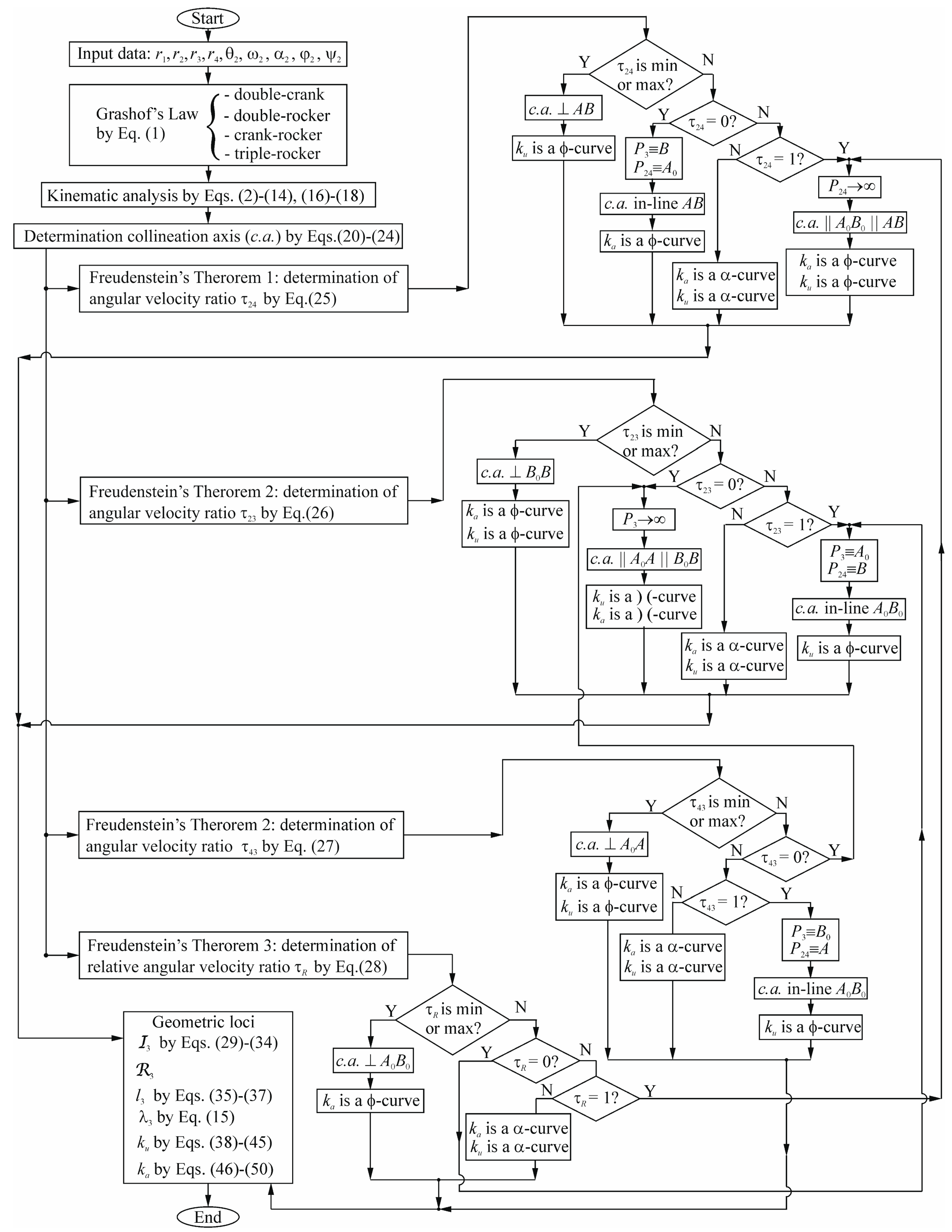
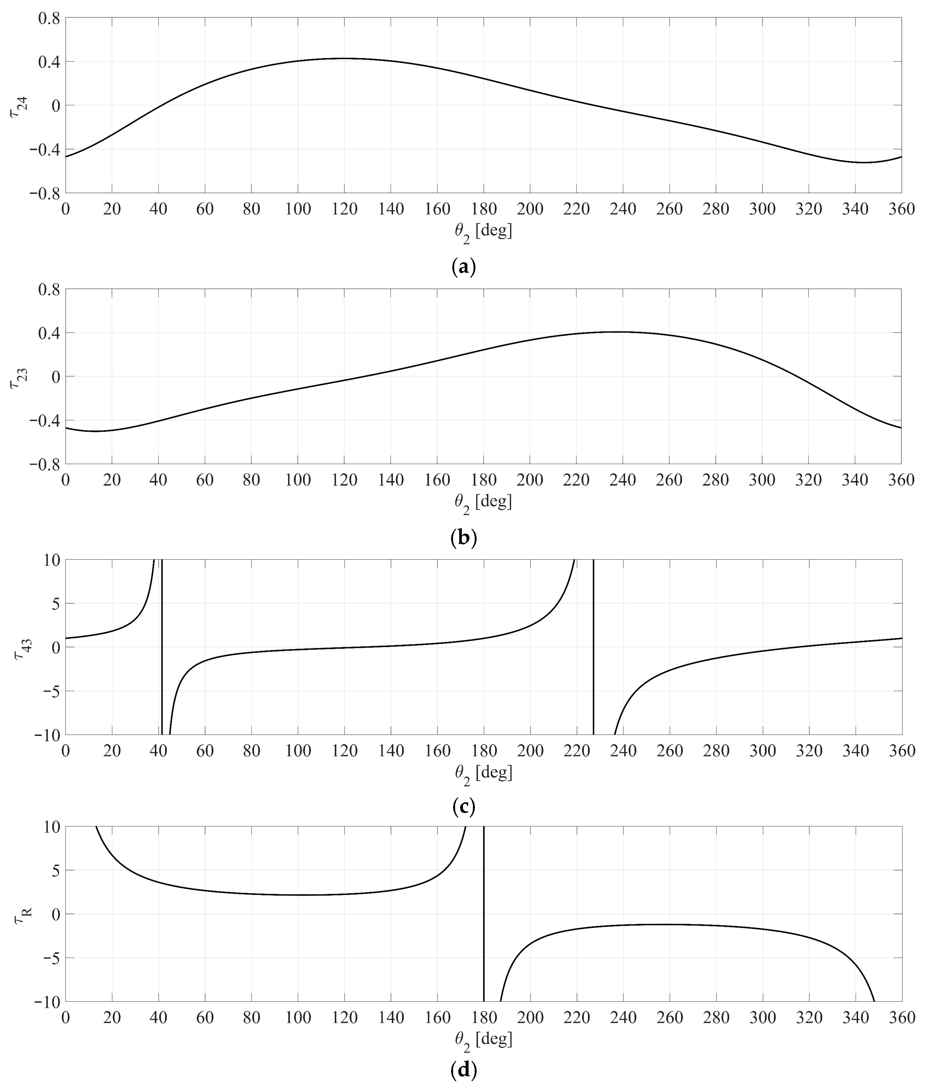
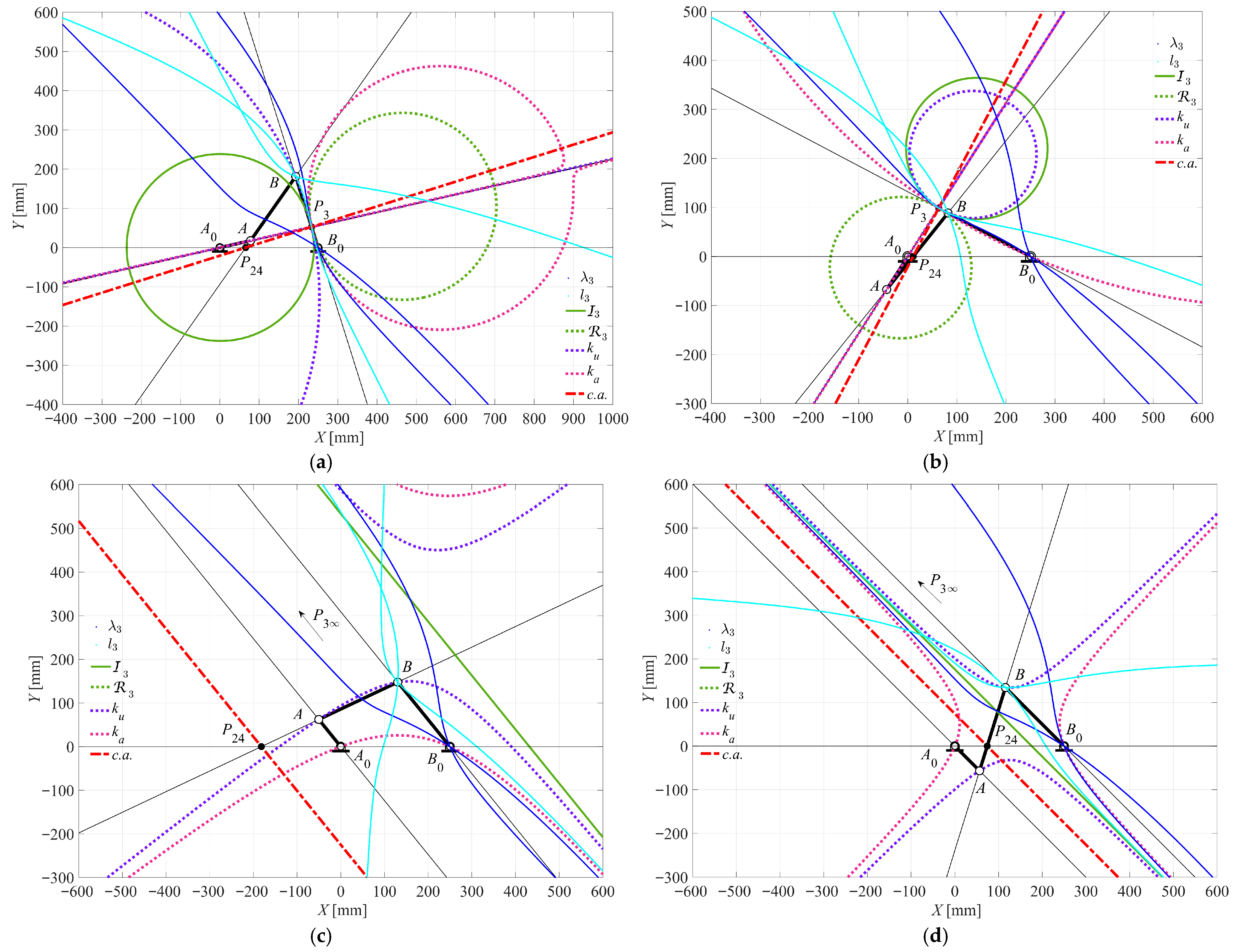
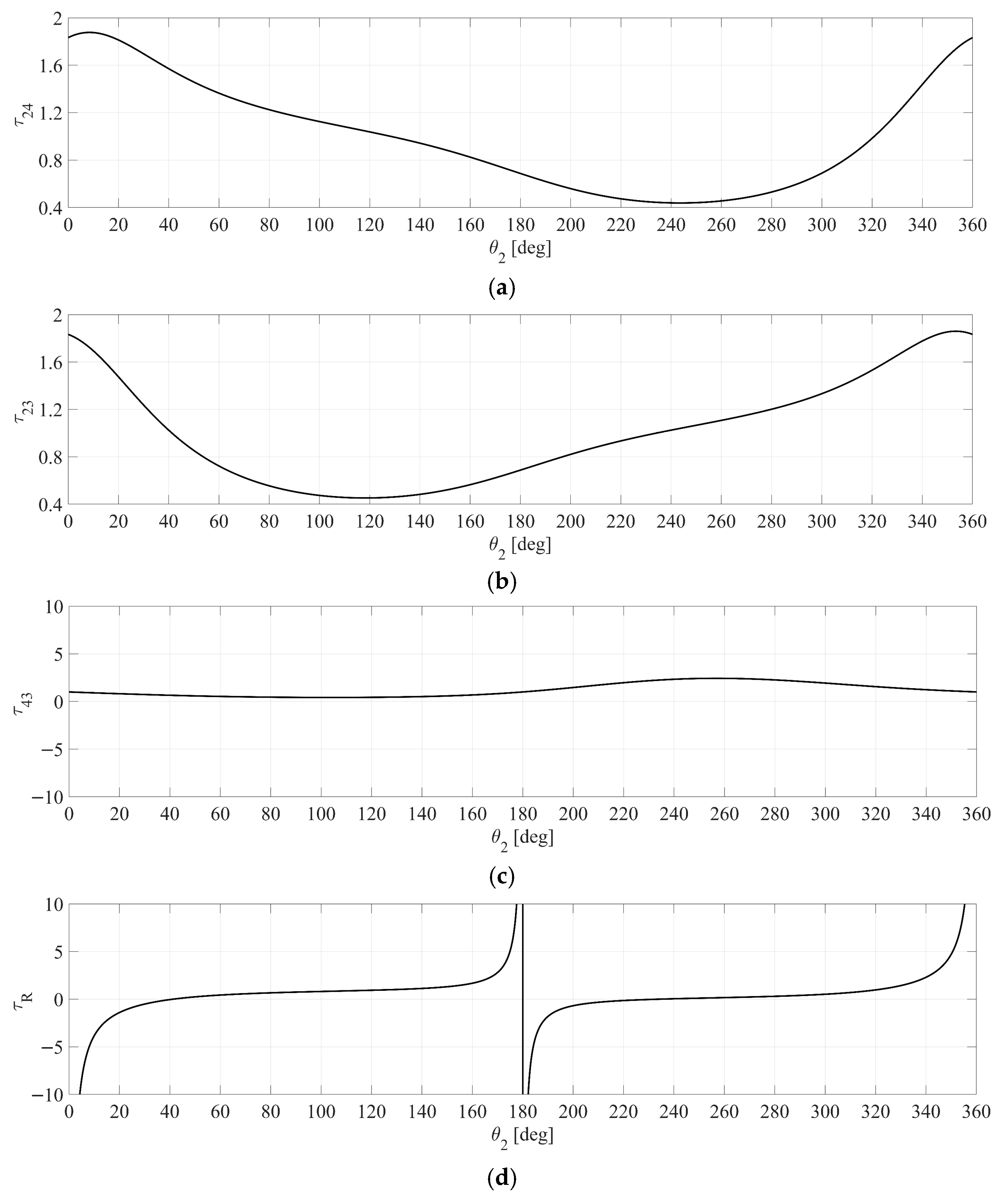
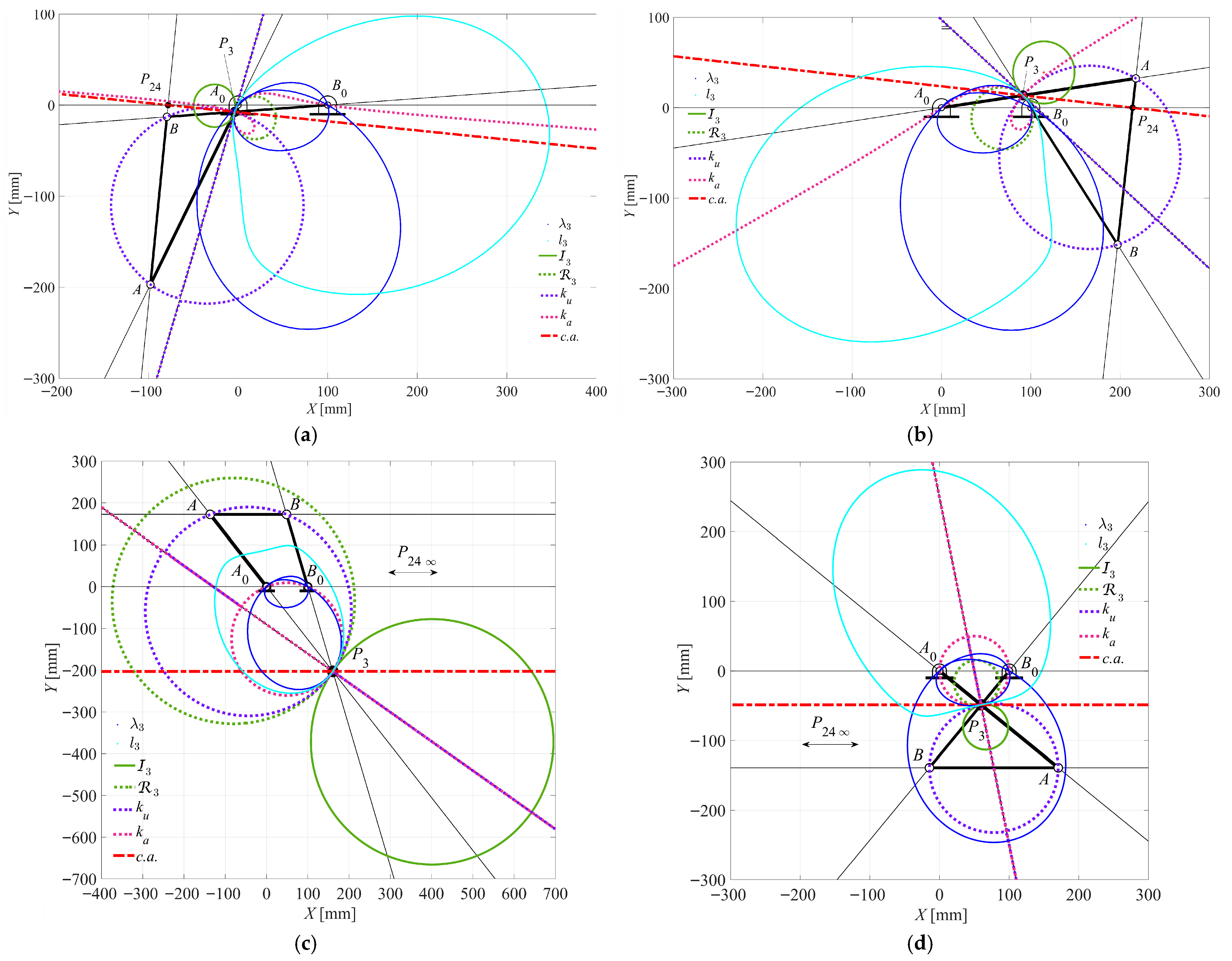
  • The minimum τ24MIN = −0.5236 occurs at θ2 = 343.7667°. At this point, the c.a. is orthogonal to the coupler link AB. The ku curve degenerates into a ϕ-curve: a circle through points A, B, and P3, and a line coinciding with the tangent t3 to the I3 at P3, as seen in Figure 9a.
  • The maximum τ24MAX = 0.4258 occurs at θ2 = 119.8000°. Similarly to the minimum, the c.a. is orthogonal to the coupler link AB, and the ku curve degenerates into a ϕ-curve, as reported in Figure 9b.
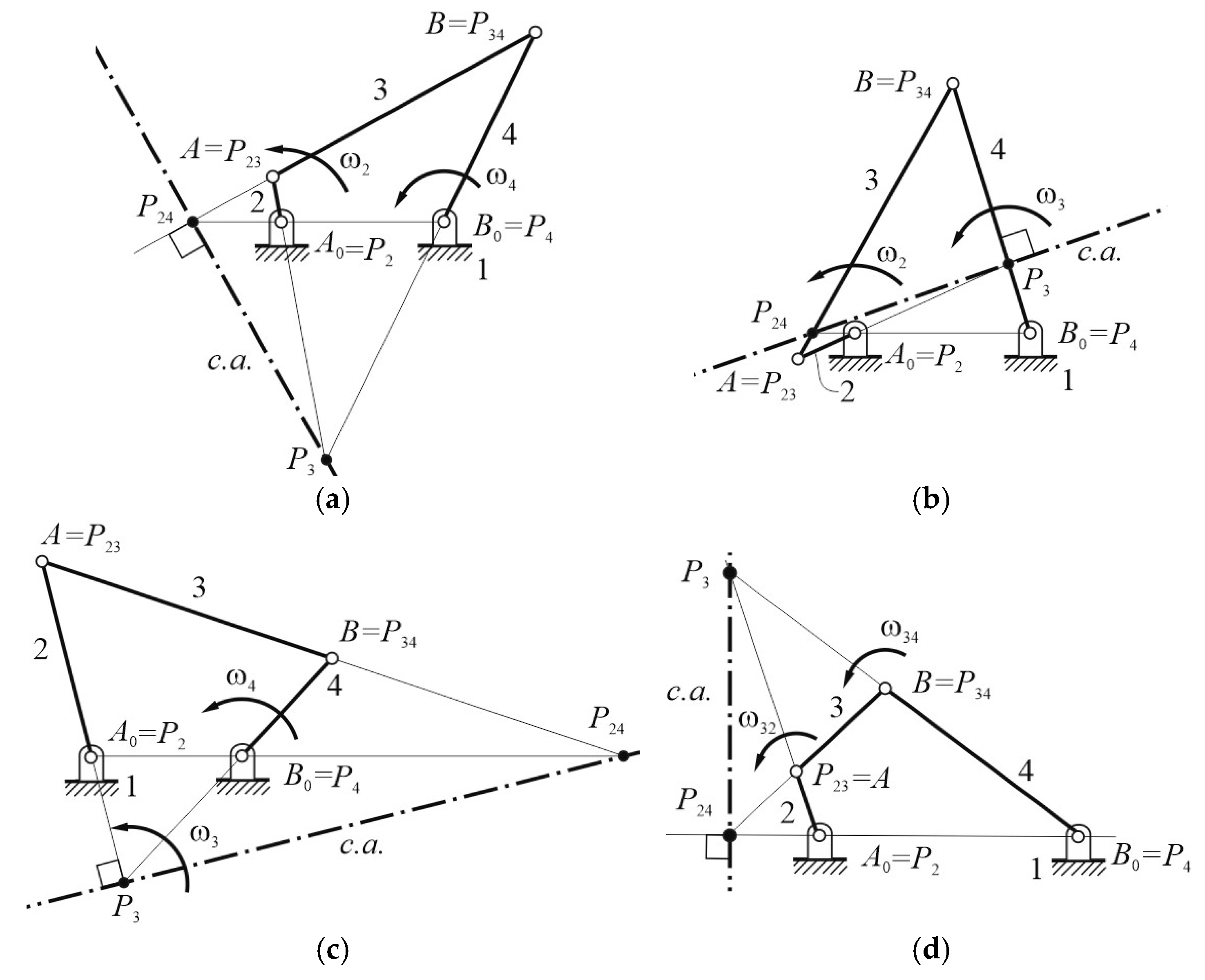
  • The τ24 becomes zero at input angles θ2 = 41.5333° and θ2 = 227.1667°. In these cases, where the mechanism is in a dead-point configuration, the c.a. is aligned with the coupler link AB. The ka curve degenerates into a ϕ-curve: a circle passing through P3 (coinciding with B) and A0 (coinciding with P24), along with a straight line coincident with the tangent t3 to the I3 at P3, as shown in Figure 9c,d.
For velocity ratio τ23, the specific results of Case 1 are as follows:
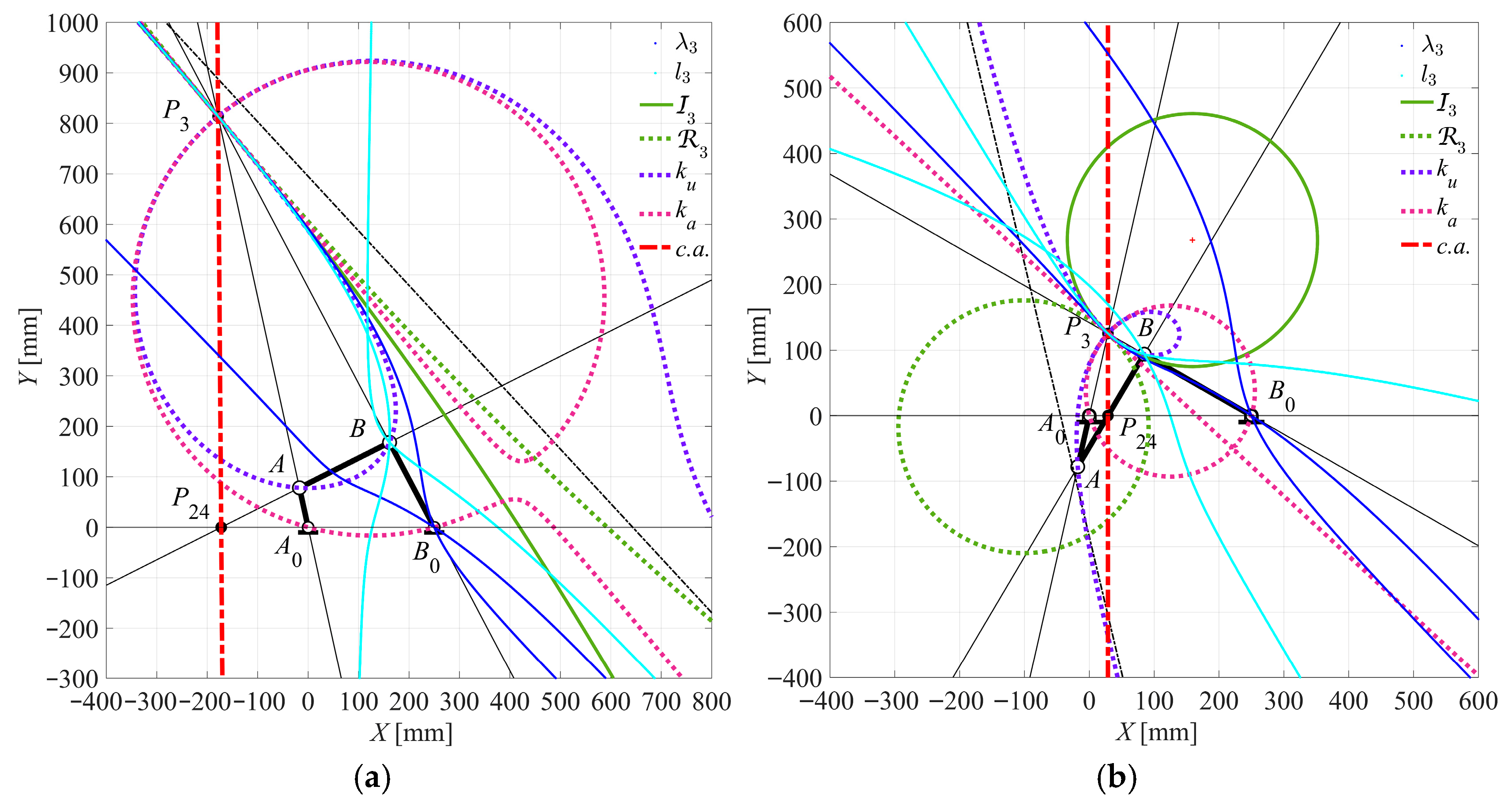
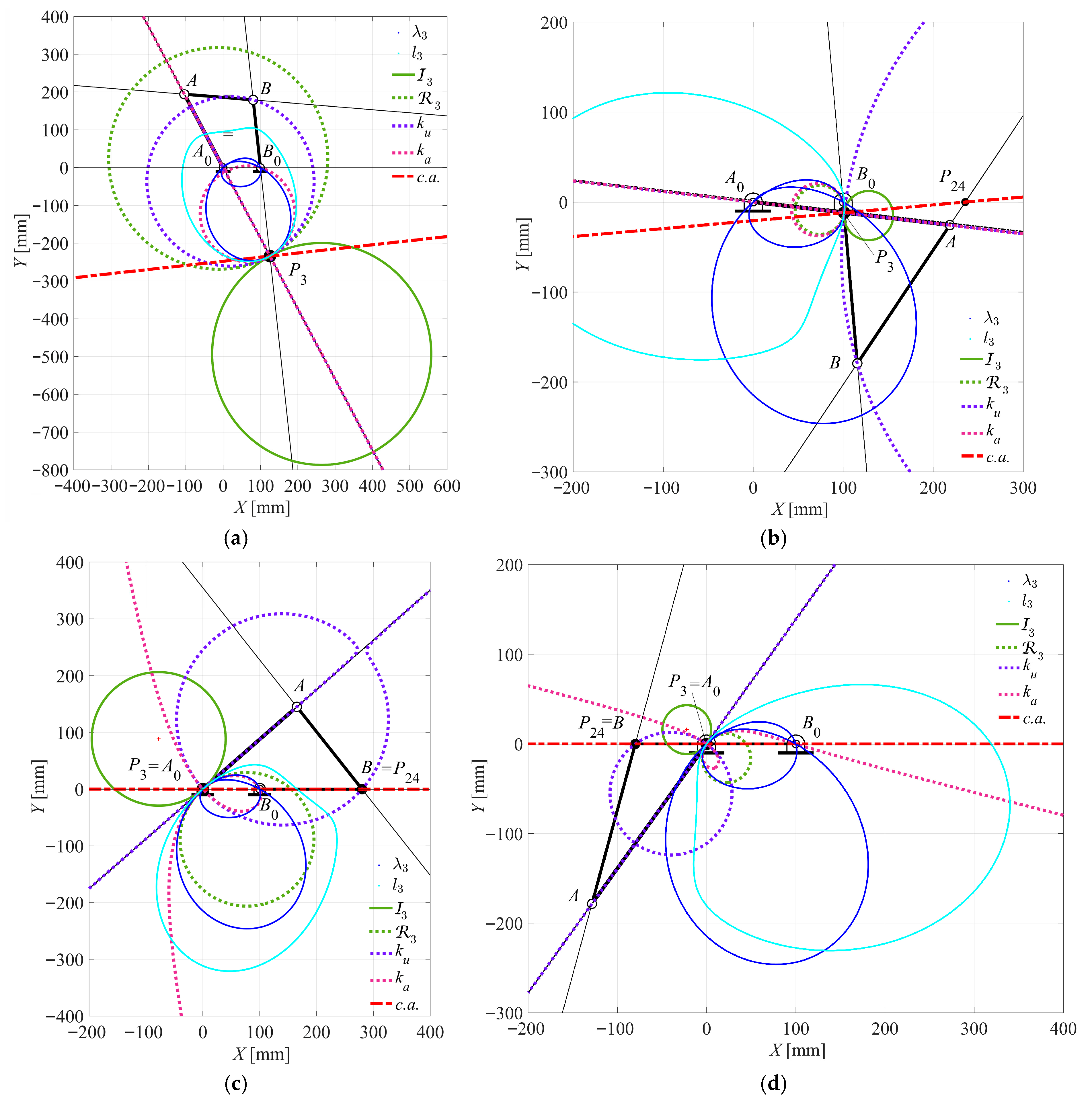
  • The minimum τ23MIN = −0.5022 and the maximum τ23MAX = 0.4059 occur at θ2 = 12.7333° and θ2 = 237.4333°, respectively. The c.a. becomes orthogonal to the coupler link B0B. Specifically, these ϕ-curves are composed of the following: a circle passing through points P3 and B0; another circle passing through points B and P3; a straight line, which is orthogonal to the tangent t3 to the I3 at P3, passing through points A0 and A, respectively, as shown in Figure 10a,b.
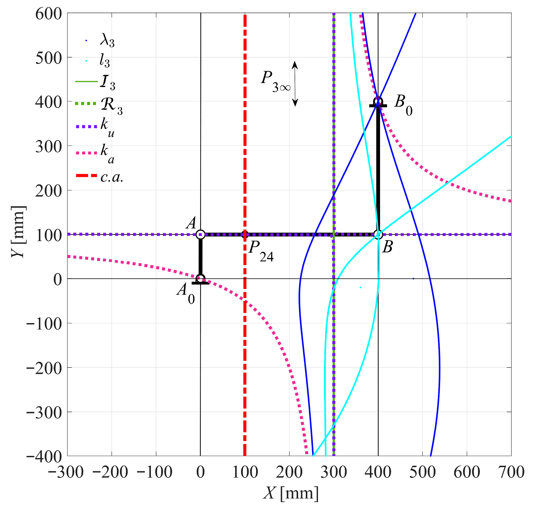
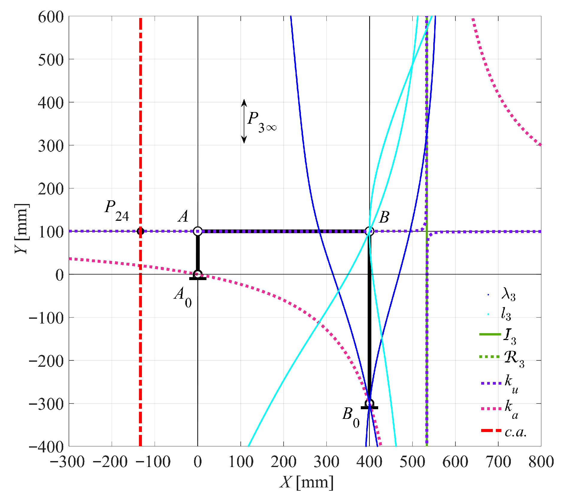
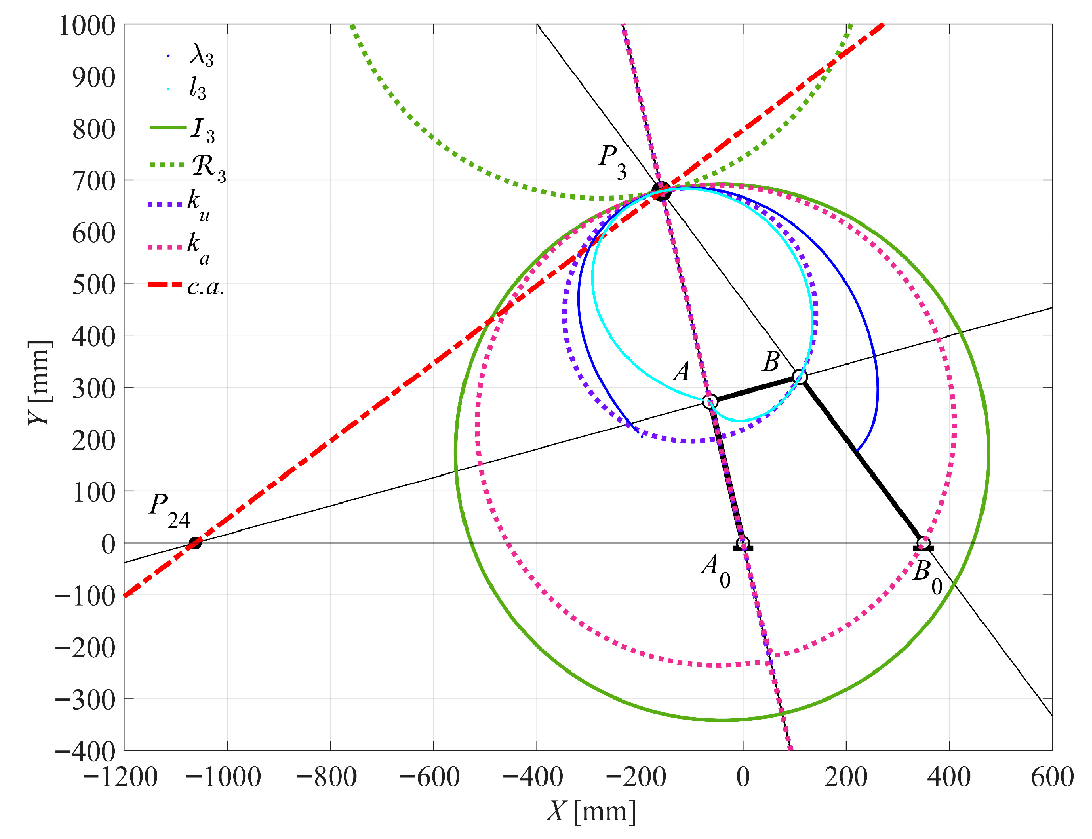
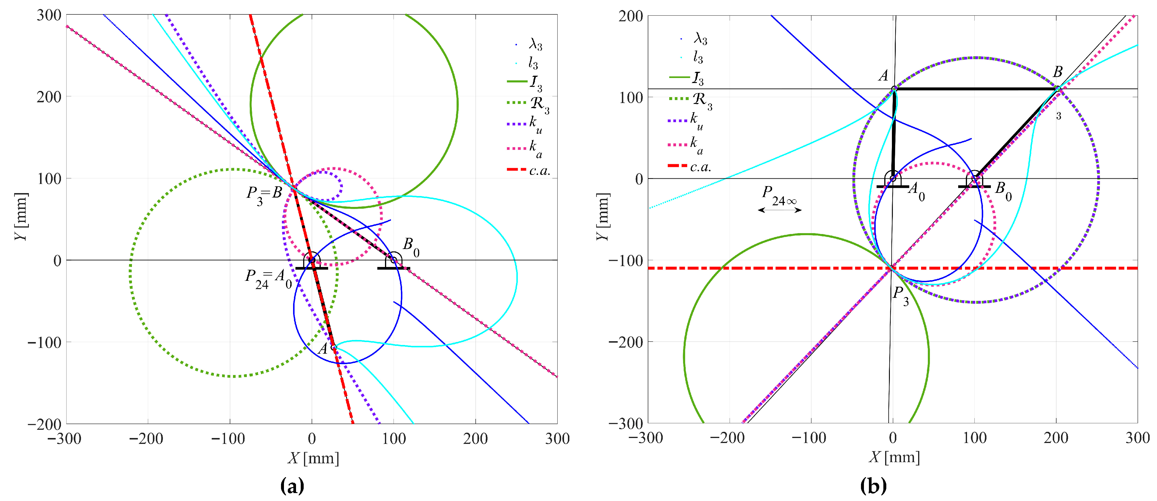
  • The τ23 equals 0 occurs at θ2 = 128.9667° and θ2 = 314.9667°. The c.a. becomes parallel to both the input link A0A and the output link B0B, with P3 tending to infinity. Under this condition, both the ka and ku curves degenerate into equilateral hyperbola (or ) ( - curves). In particular, the ka curve passes through points A0, B0, and P3 (at infinity), while the ku curve passes through points A, B, and P3. Additionally, each branch of these curves is tangent to the I3, as shown in Figure 10c,d.
For velocity ratio τ43, the specific results of Case 1 are as follows:
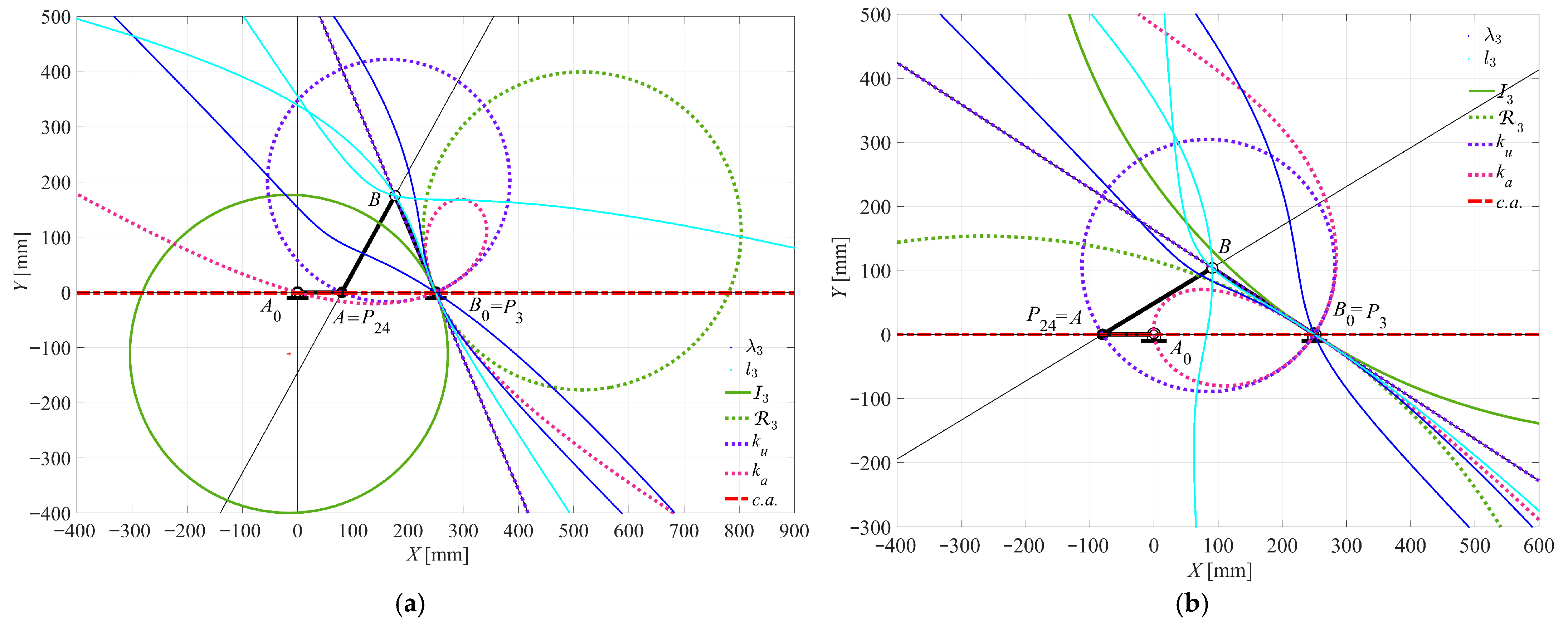
  • The τ43 equals 1 at θ2 = 0° and θ2 = 180°. The c.a. aligns with the fixed link A0B0. P24 coincides with point A, and P3 coincides with point B0. The ku curve degenerates into a ϕ-curve (a circle through P3 and A0, and a line coincident to t3 to the I3 at point P3, while also passing through A), as shown in Figure 11a,b.
For velocity ratio τR, the specific results of Case 1 are as follows:
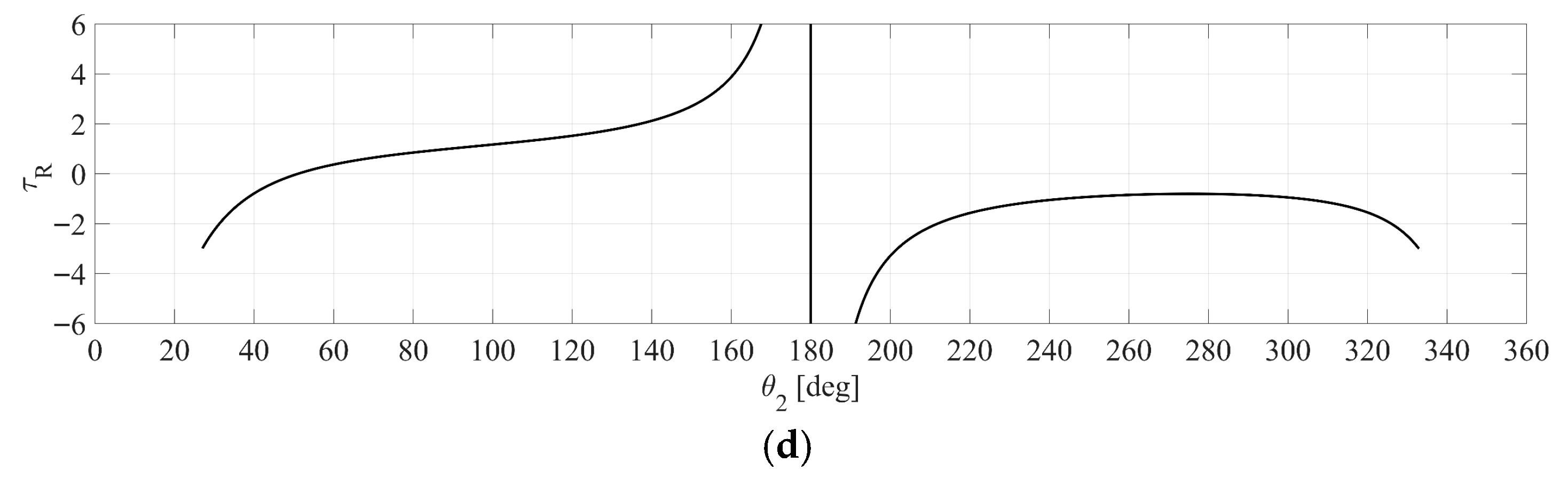
  • The minimum τRMINREL = 2.5150 and maximum τRMAXREL = −1.2017 relative values occur at θ2 = 102.3667° and θ2 = 257.1000°, respectively. The c.a. becomes orthogonal to the fixed link A0B0. The ka curve degenerates into a ϕ-curve (a circle passing through points P3, A0, and B0, as well as a straight line (coincident to the tangent t3 to I3 at point P3), as shown in Figure 12a,b.
Cases 2 and 3, which represent the asymptotic configurations of a crank-rocker mechanism in which links 2, 3, and 4 are mutually orthogonal, are presented in Figure 13 and Figure 14.
When τ24 reaches its minimum τ24MIN and maximum τ24MAX values at θ2 = 90.0000°, the c.a. becomes parallel to both the input link A0A and the output link B0B. Simultaneously, it becomes perpendicular to the coupler link AB. In this specific configuration, point P3 tends to infinity, causing both the ku and ka curves to degenerate. Specifically, ka degenerates into an equilateral hyperbola that passes through points A0, B0, and P3 (at infinity), as well as a line at infinity. Meanwhile, ku degenerates into two straight lines: the first passes through points A and B, the second is parallel to P3, and the third is a line at infinity.
Case 4: A double-crank mechanism is analyzed in detail, with its results presented in Figure 15, Figure 16, Figure 17 and Figure 18 and Table 3. The analysis focuses on the behavior of various velocity ratios (τ24, τ23, τ43, and τR) as functions of the input angle θ2, as shown in Figure 15. Specific attention is given to the maximum and minimum values of these ratios, as well as where they equal 0 or 1, as seen in Figure 15. For velocity ratio τ24, the specific results of Case 4 are as follows:
  • The minimum τ24MIN = 0.4390 and the maximum τ24MAX = 1.8771 at θ2 = 243.5667° and θ2 = 8.4667°, respectively. At these points, the c.a. is orthogonal to the coupler link AB. These configurations shown in Figure 16a,b, yielding the same results as those presented in Figure 9a,b.
  • The τ24 becomes 1 at input angles θ2 = 128.3667° and θ2 = 320.8333°. The c.a. becomes parallel to both the coupler link AB and fixed link A0B0. Under this condition, both the ka and ku curves degenerate into ϕ-curves, which are composed of the following: a circle passing through points P3, A0, and B0; another circle passing through points A, B, and P3; a straight line that is orthogonal to the tangent t3 to the I3 at point P3, as illustrated in Figure 16c,d.
For velocity ratio τ23, the specific results of Case 4 are as follows:
  • The minimum τ23MIN = 0.4528 and the maximum τ23MAX = 1.8600 at θ2 = 118.1667° and θ2 = 353.3333°, respectively. At these points, the c.a. is orthogonal to the output link B0B. These configurations shown in Figure 17a,b, yielding the same results as those presented in Figure 10a,b.
  • The τ23 equals 1 occurs at θ2 = 41.2667° and θ2 = 234.2333°. In these cases, where the mechanism is in a dead-point configuration, the c.a. is in-line with the coupler link AB. The ku curve degenerates into a ϕ-curve, which is a circle passing through points P3 (coinciding with A0) and B (coinciding with P24). Additionally, there is a straight line that is coincident to the tangent t3 to the I3 at point P3, as shown in Figure 17c,d.
For the velocity ratio τ43, the specific results of Case 4 are as follows:
  • The minimum τ43MIN = 0.4207 and the maximum τ43MAX = 2.4292 at θ2 = 104.1000° and θ2 = 256.7333°, respectively. At these points, where the mechanism is in a dead-point configuration, the c.a. becomes orthogonal to the fixed link A0A. Both the ka and ku curves degenerates into a ϕ-curve, which is specifically defined by the following: a circle that passes through points P3 and A0; another circle that passes through points P3 and A; a straight line that passes through points P3 and B; a straight line that passes through points and P3 and B0. The latter two lines are also coincident to the tangent t3 to the circle I3 at point P3, as shown in Figure 18a,b.
  • The τ43 equals 1 at θ2 = 0° and θ2 = 180°. The c.a. aligns with the fixed link A0B0, and these configurations shown in Figure 18c,d yield the same results as those shown in Figure 11a,b.
Case 5: A double-rocker mechanism is analyzed in detail, with its results presented in Figure 19, Figure 20, Figure 21 and Figure 22 and Table 4. The analysis focuses on the behavior of various velocity ratios (τ24, τ23, τ43, and τR) as functions of the input angle θ2. Figure 19 highlights the minimum and maximum angular velocity ratios for each velocity ratio, their corresponding θ2 values, and the specific positions of the c.a. relative to the mechanism’s links.
As shown in Figure 20a, when τ24 equals 0 at θ2 = 57.2667°, the mechanism is in a dead-point configuration. In this case, the c.a. is aligned with the coupler link AB, consistent with the results presented in Figure 9c. Conversely, τ24 equals 1 at θ2 = 123.6000°, the c.a. is parallel to both coupler link AB and fixed link A0B0, as depicted in Figure 20b. This configuration matches the results shown in Figure 16c,d. Similarly, as illustrated in Figure 21, when τ23MAX = −0.6733 at θ2 = 103.1000°, the c.a. is perpendicular to the output link B0B. This configuration aligns with the results shown in Figure 10b and Figure 17b.
Referring to Figure 22, when τ43MAXREL = −0.8487 at θ2 = 112.4333°, the c.a. is perpendicular the input link A0A. This configuration is consistent with the result shown in Figure 18b.
Case 6: A triple-rocker mechanism is analyzed in detail, with its results presented in Figure 23, Figure 24, Figure 25 and Figure 26 and Table 5. The analysis focuses on the behavior of various velocity ratios (τ24, τ23, τ43, and τR) as functions of the input angle θ2, as seen in Figure 23. Similar patterns are observed in Figure 24a when τ24 equals 0 at θ2 = 284.1333°. This dead-point configuration aligns with the results previously presented in Figure 9b,d and Figure 20a.
When τ24 equals 1 at θ2 = 88.9667°, the asymptotic configuration, shown in Figure 24b, where links 2 and 3 are mutually orthogonal, aligns with the results shown in Figure 16c,d and Figure 20b. Furthermore, as illustrated in Figure 25a, when τ23 equals 0 at θ2 = 316.3000°, this configuration aligns with the results presented in Figure 10c,d. When τ23 equals 1 at θ2 = 51.0000°, as shown in Figure 25b, this dead-point configuration aligns with the results presented in Figure 17c,d. Lastly, as shown in Figure 26, when τ43 equals 1 at θ2 = 180.0000°, this dead-point configuration is consistent with the results shown in Figure 11a,b and Figure 18c,d.

6. Conclusions

A general algorithm to determine the coupler link geometric loci, such as centrodes, inflection and return circles, as well as circling-point and centering-point curves, has been formulated as based on Grashof’s law and Freudenstein’s theorems. The main novelty consists of four diagrams of the angular–velocity ratios versus the mechanism driving angle, since these diagrams allows the identification of all mechanism configurations, with different geometric loci degenerate forms such as straight lines, including the line at infinity, ϕ-curves, and/or equilateral hyperbolas. The proposed algorithm has been implemented in Matlab and validated by means of several significant examples. Asymptotic and dead-point configurations are some of these particular cases, which could be useful for synthesis purposes, as well as for designing six-bar dwell mechanisms or straight-line path generators

Author Contributions

Conceptualization, G.F., C.L. and L.T.; methodology G.F., C.L. and L.T.; software, C.L.; validation, G.F., C.L. and L.T.; formal analysis, G.F. and C.L.; investigation, G.F., C.L. and L.T.; resources, G.F. and L.T.; data curation, G.F., C.L. and L.T.; writing—original draft preparation, G.F., C.L. and L.T.; writing—review and editing, G.F., C.L. and L.T.; visualization, C.L. and L.T.; supervision, G.F.; project administration, G.F.; funding acquisition, G.F. All authors have read and agreed to the published version of the manuscript.

Funding

This research received no external funding.

Data Availability Statement

Data is contained within the article.

Conflicts of Interest

The authors declare no conflicts of interest.

Nomenclature

c.a.collineation axis
hthe distance of a generic point P that has a stationary curvature from P3
hAthe distance of a point A that has a stationary curvature from P3
hBthe distance of a point B that has a stationary curvature from P3
I3inflection circle of coupler link 3
kacentering-point curve or centers of cubic of stationary curvature
kucircling-point curve or cubic of stationary curvature
l3moving centrode of coupler link 3
Mthe motion invariant
Nthe motion invariant
N3the y-axis of the canonical reference frame
OXYthe fixed frame
O3x3y3the moving frame
P3T3N3canonical reference frame
P3instant center of rotation (ICR) of the coupler link 3
P24relative ICR of the output link 4 with respect to the input link 2
3return circle of coupler link 3
r1the length of the fixed link A0B0, expressed in [mm]
r2the length of the input link A0A, expressed in [mm]
r3the length of the coupler link AB, expressed in [mm]
r4the length of the output link B0B, expressed in [mm]
ri (for i = 1, …, 4)position vector for link i
T3the x-axis of the canonical reference frame, that is tangent to both centrodes l3 and λ3,
Thomogeneous transformation matrix
α-curve(strophoids) circular cubic curves with a node where the tangents are orthogonal
αi (i = 1, 2, 3, 4)the magnitude of the angular acceleration of link i, expressed in [rad/s2]
αi (i = 1, 2, 3, 4)the angular acceleration vector of link i, expressed as [0 0 αi]
βthe oriented angle between the X-axis and T3
δthe diameter of the inflection circle I3.
θi (i = 1, 2, 3, 4)the counterclockwise angle between the position vector ri and a reference axis X, measured in radians [rad].
λ3fixed centrode of coupler link 3
τ23angular velocity ratio between the coupler link 3 and the input link 2, (adjacent to the frame), [dimensionless]
τ24angular velocity ratio between the input link 2 and the output link 4, (adjacent to the frame), [dimensionless]
τ43angular velocity ratio between the coupler link 3 and the frame-adjacent link 4, [dimensionless]
τRrelative angular velocity ratios between the coupler link and each of the frame-adjacent links, specifically, ω32 and ω34, [dimensionless]
ϕ-curvea special case of a strophoid that degenerates into a circle and a straight line
φi (i = 1, 2, 3, 4)the magnitude of the angular jerk of link i, expressed in [rad/s3]
φi (i = 1, 2, 3, 4)the angular jerk vector of link i, expressed as [0 0 φi]
ψi (i = 1, 2, 3, 4)the magnitude of the angular snap of link i, expressed in [rad/s4]
ψi (i = 1, 2, 3, 4)the angular snap vector of link i, expressed as [0 0 ψi]
ωi (i = 1, 2, 3, 4)the magnitude of the angular velocity of link i, expressed in [rad/s].
ωi (i = 1, 2, 3, 4)the angular velocity vector of link i, expressed as [0 0 ωi]
Ψthe angle made between the N3-axis with the oriented segment P3P of generic point P
ΨAthe angle made between the N3-axis with the oriented segment P3A
ΨBthe angle made between the N3-axis with the oriented segment P3B
) ( - curve (equilateral hyperbola)a special case of a strophoid that degenerates into an equilateral hyperbola and the line at infinity.

References

  1. Freudenstein, F. On the Maximum and Minimum Velocities and the Accelerations in Four-Link Mechanisms. Trans. Am. Soc. Mech. Eng. 1956, 78, 779–785. [Google Scholar] [CrossRef]
  2. Wu, L.-I.; Wu, S.-H. A note on Freudenstein’s theorem. Mech. Mach. Theory 1998, 33, 139–149. [Google Scholar] [CrossRef]
  3. Goessner, S. Vectorial Proof of the Freudenstein Theorem. 2019. Available online: https://www.researchgate.net/publication/336262310_Vectorial_Proof_of_the_Freudenstein_Theorem (accessed on 9 July 2025).
  4. Hayes, M.J.D.; Rotzoll, M.; Iraei, A.E.; Nichol, A.; Bucciol, Q. Algebraic Differential Kinematics of Planar 4R Linkages. In Proceedings of the 2021 20th International Conference on Advanced Robotics (ICAR), Ljubljana, Slovenia, 6–10 December 2021; pp. 1060–1065. [Google Scholar]
  5. Dijksman, E.A.; Smals, A.T.J.S. Symmetrical coupler curves approximating a straight-line (degenerate case). In Proceedings of the First International Applied Mechanical Systems Design Conference (IAMSDC-1), Nashville, TN, USA, 11–14 June 1989; pp. P33.17–P33.31. [Google Scholar]
  6. Chiang, C.H. Simplified graphical acceleration analysis of four-bar linkages. J. Mech. 1970, 5, 549–562. [Google Scholar] [CrossRef]
  7. Dijksman, E.A. Jerk-free Geneva wheel driving. J. Mech. 1966, 1, 235–283. [Google Scholar] [CrossRef]
  8. Claussen, U.; Dizioǧlu, B. The special cases of the circling-point curve and centering-point curve for the general four-bar linkage. J. Mech. 1966, 1, 145–154. [Google Scholar] [CrossRef]
  9. Wu, L.; Cai, J.; Dai, J.S. Analyzing Higher-Order Curvature of Four-Bar Linkages with Derivatives of Screws. Machines 2024, 12, 576. [Google Scholar] [CrossRef]
  10. Eddie Baker, J. Screw system algebra applied to special linkage configurations. Mech. Mach. Theory 1980, 15, 255–265. [Google Scholar] [CrossRef]
  11. Gosselin, C.; Angeles, J. Singularity analysis of closed-loop kinematic chains. IEEE Trans. Robot. Autom. 1990, 6, 281–290. [Google Scholar] [CrossRef]
  12. Kimbrell, J.E.; Hunt, K.H. Coupler point-paths and line-envelopes of 4-bar linkages in asymptotic configurations. Mech. Mach. Theory 1981, 16, 311–320. [Google Scholar] [CrossRef]
  13. Chase, T.R.; Mirth, J.A. Circuits and Branches of Single-Degree-of-Freedom Planar Linkages. J. Mech. Des. 1993, 115, 223–230. [Google Scholar] [CrossRef]
  14. Chung, W.-Y. Double configurations of five-link Assur kinematic chain and stationary configurations of Stephenson six-bar. Mech. Mach. Theory 2007, 42, 1653–1662. [Google Scholar] [CrossRef]
  15. Pennock, G.R.; Kamthe, G.M. Study of Dead-Centre Positions of Single-Degree-of-Freedom Planar Linkages Using Assur Kinematic Chains. Proc. Inst. Mech. Eng. Part C J. Mech. Eng. Sci. 2006, 220, 1057–1074. [Google Scholar] [CrossRef]
  16. Tsai, C.-C.; Wang, L.T. On the dead-centre position analysis of Stephenson six-link linkages. Proc. Inst. Mech. Eng. Part C J. Mech. Eng. Sci. 2006, 220, 1393–1404. [Google Scholar] [CrossRef]
  17. Yan, H.-S.; Wu, L.-I. The stationary configurations of planar six-bar kinematic chains. Mech. Mach. Theory 1988, 23, 287–293. [Google Scholar] [CrossRef]
  18. Yan, H.-S.; Wu, L.-L. On the Dead-Center Positions of Planar Linkage Mechanisms. J. Mech. Transm. Autom. Des. 1989, 111, 40–46. [Google Scholar] [CrossRef]
  19. Veldkamp, G.R. The instantaneous motion of a line in a t-position. Mech. Mach. Theory 1983, 18, 439–444. [Google Scholar] [CrossRef]
  20. Figliolini, G.; Lanni, C.; Tomassi, L. Synthesis and Analysis of Stephenson III Six-Bar Motion Generators With an Instantaneous Stop Link. J. Mech. Robot. 2024, 17, 044510. [Google Scholar] [CrossRef]
  21. Figliolini, G.; Lanni, C.; Tomassi, L. First- and Second-Order Centrodes of Both Coupler Links of Stephenson III Six-Bar Mechanisms. Machines 2025, 13, 93. [Google Scholar] [CrossRef]
  22. Figliolini, G.; Pennestrì, E. Synthesis of Quasi-Constant Transmission Ratio Planar Linkages. J. Mech. Des. 2015, 137, 102301. [Google Scholar] [CrossRef]
  23. Figliolini, G.; Lanni, C.; Tomassi, L.; Ortiz, J. Eight-Bar Elbow Joint Exoskeleton Mechanism. Robotics 2024, 13, 125. [Google Scholar] [CrossRef]
  24. Lanni, C.; Figliolini, G.; Tomassi, L. Higher-Order Centrodes and Bresse’s Circles of Slider-Crank Mechanisms. In Proceedings of the ASME 2023 International Design Engineering Technical Conferences and Computers and Information in Engineering Conference, Boston, MA, USA, 20–23 August 2023. [Google Scholar]
  25. Stachel, H. Strophoids, a family of cubic curves with remarkable properties. J. Ind. Des. Eng. Graph. 2015, 10, 65–72. [Google Scholar]
  26. Dijksman, E.A. Motion Geometry of Mechanisms; Cambridge University Press: Cambridge, UK, 1976. [Google Scholar]
  27. Hunt, K.H. Kinematic Geometry of Mechanisms; Clarendon Press: Oxford, UK, 1978. [Google Scholar]
  28. Cera, M.; Pennestri, E. Engineering Kinematics: Curvature Theory of Plane Motion; Amazon Digital Services LLC—Kdp: Seattle, WA, USA, 2023. [Google Scholar]
  29. Lakshminarayana, K. On the Carter-Hall circle and its application. J. Mech. 1971, 6, 517–532. [Google Scholar] [CrossRef]
  30. Dijksman, E.A. Coordination of Coupler-Point Positions and Crank Rotations in Connection with Roberts’ Configuration. J. Eng. Ind. 1969, 91, 55–65. [Google Scholar] [CrossRef]
  31. Chiang, C.H. Kinematics and Design of Planar Mechanisms; Krieger Publishing Company: Malabar, FL, USA, 2000. [Google Scholar]
  32. Hartenberg, R.S.; Denavit, J. Kinematic Synthesis of Linkages; McGraw-Hill: New York, NY, USA, 1964. [Google Scholar]
  33. Hirschhorn, J. Kinematics and Dynamics of Plane Mechanisms; McGraw-Hill: New York, NY, USA, 1962. [Google Scholar]
  34. Hain, K. Applied Kinematics; McGraw-Hill: New York, NY, USA, 1967. [Google Scholar]
  35. Li, J.; Hu, Y.; Yang, S.X. A Novel Knowledge-Based Genetic Algorithm for Robot Path Planning in Complex Environments. IEEE Trans. Evol. Comput. 2025, 29, 375–389. [Google Scholar] [CrossRef]
  36. Sheta, A.N.; Sedhom, B.E.; Pal, A.; Moursi, M.S.E.; Eladl, A.A. Machine-Learning-Based Adaptive Settings of Directional Overcurrent Relays With Double-Inverse Characteristics for Stable Operation of Microgrids. IEEE Trans. Ind. Inform. 2025, 21, 584–593. [Google Scholar] [CrossRef]
Figure 1. Four-bar mechanism: (a) vector loop; (b) kinematic analysis, where the blue color is for the velocity vectors, and the red one is for the acceleration vectors.
Symmetry 17 01171 g001
Figure 2. Four-bar mechanism: collineation axis c.a., inflection circle I3, return circle 3, fixed centrode λ3, and moving centrode l3.
Symmetry 17 01171 g002
Figure 3. Location of collineation axis c.a.: (a) Freudenstein’s Theorem 1 τ24; (b) Freudenstein’s Theorem 2 τ23; (c) Freudenstein’s Theorem 2 τ43; (d) Freudenstein’s Theorem 3 τR.
Symmetry 17 01171 g003
Figure 4. Four-bar linkage: collineation axis c.a.; circling-point ku and centering- point ka curves.
Symmetry 17 01171 g004
Figure 5. Four values for velocity ratios, τ24, τ23, τ43, and τR versus input angle θ2.
Symmetry 17 01171 g005
Figure 6. Some special cases of ku and ka curves: (a) ku as a ϕ-curve; (b) both ku and ka are ϕ-curves; (c) ku as two straight lines (one at infinity) and ka as an equilateral hyperbola and a line at infinity.
Symmetry 17 01171 g006
Figure 7. Flowchart of the proposed algorithm to find and analyze all configurations of four-bar linkages with different geometric loci degenerate forms.
Symmetry 17 01171 g007
Figure 8. Case 1 (Crank-rocker) diagrams of the velocity ratios versus θ2: (a) τ24; (b) τ23; (c) τ43; (d) τR.
Symmetry 17 01171 g008
Figure 9. Case 1 (Crank-rocker): (a) θ2 = 119.8000° for τ24MAX; (b) θ2 = 343.7667° for min τ24MIN; (c) θ2 = 41.5333° for τ24 = 0; (d) θ2 = 227.1667° for τ24 = 0.
Symmetry 17 01171 g009
Figure 10. Case 1 (Crank-rocker): (a) θ2 = 12.7333° for τ23MIN; (b) θ2 = 237.4333° for τ23MAX; (c) θ2 = 128.9667° for τ23 = 0; (d) θ2 = 314.9667° for τ23 = 0.
Symmetry 17 01171 g010
Figure 11. Case 1 (Crank-rocker): (a) θ2 = 0° for τ43 = 1; (b) θ2 = 180° for τ43 = 1.
Symmetry 17 01171 g011
Figure 12. Case 1 (Crank-rocker): (a) θ2 = 102.3667° for τRMINREL; (b) θ2 = 257.1000° for τRMAXREL.
Symmetry 17 01171 g012
Figure 13. Case 2 (Crank-rocker): θ2 = 90.0000° for τ24MIN.
Symmetry 17 01171 g013
Figure 14. Case 3 (Crank-rocker): θ2 = 90.0000° for τ24MAX.
Symmetry 17 01171 g014
Figure 15. Case 4 (Double-crank) diagrams of the velocity ratios versus θ2: (a) τ24; (b) τ23; (c) τ43; (d) τR.
Symmetry 17 01171 g015
Figure 16. Case 4 (Double–crank): (a) θ2 = 8.4667° for τ24MAX; (b) θ2 = 243.5667° for τ24MIN; (c) θ2 = 128.3667° for τ24 = 1; (d) θ2 = 320.8333° for τ24 = 1.
Symmetry 17 01171 g016
Figure 17. Case 4 (Double-crank): (a) θ2 = 118.1667° for τ23MIN; (b) θ2 = 353.3333° for τ23MAX; (c) θ2 = 41.2667° for τ23 = 1; (d) θ2 = 234.2333° for τ23 = 1.
Symmetry 17 01171 g017
Figure 18. Case 4 (Double-crank): (a) θ2 = 104.1000° for τ43MIN; (b) θ2 = 256.7333° for τ43MAX; (c) θ2 = 0° for τ43 = 1; (d) θ2 = 180° for τ43 = 1.
Symmetry 17 01171 g018
Figure 19. Case 5 (Double-rocker) diagrams of the velocity ratios versus θ2: (a) τ24; (b) τ23; (c) τ43; (d) τR.
Symmetry 17 01171 g019
Figure 20. Case 5 (Double-rocker): (a) θ2 = 57.2667° for τ24 = 0; (b) θ2 = 123.6000° for τ24 = 1.
Symmetry 17 01171 g020
Figure 21. Case 5 (Double-rocker): θ2 = 103.1000° for τ24MAX.
Symmetry 17 01171 g021
Figure 22. Case 5 (Double-rocker): θ2 = 112.4333° for τ43MAXREL.
Symmetry 17 01171 g022
Figure 23. Case 6 (Triple-rocker) diagrams of the velocity ratios versus θ2: (a) τ24; (b) τ23; (c) τ43; (d) τR.
Symmetry 17 01171 g023aSymmetry 17 01171 g023b
Figure 24. Case 6 (Triple-rocker): (a) θ2 = 284.1333° for τ24 = 0; (b) θ2 = 88.9667° for τ24 = 1.
Symmetry 17 01171 g024
Figure 25. Case 6 (Triple-rocker): (a) θ2 = 316.3000° for τ23 = 0; (b) θ2 = 51.0000° for τ23 = 1.
Symmetry 17 01171 g025
Figure 26. Case 6 (Triple-rocker): θ2 = 180° for τ43 = 1.
Symmetry 17 01171 g026
Table 1. Numerical examples.
Case of Studyr1 (A0B0) [mm]r2 (A0A) [mm]r3 (AB) [mm]r4 (B0B) [mm]Figures
Case 1: Crank-rocker25080200190Figure 8, Figure 9, Figure 10, Figure 11 and Figure 12
Case 2: Crank-rocker400100400300Figure 13
Case 3: Crank-rocker400100400400Figure 14
Case 4: Double-crank100220185180Figure 15, Figure 16, Figure 17 and Figure 18
Case 5: Double-rocker350280180400Figure 19, Figure 20, Figure 21 and Figure 22
Case 6: Triple-rocker100110200150Figure 23, Figure 24, Figure 25 and Figure 26
Table 2. Case 1 (Crank-rocker): Special cases of ku and ka according to Freudenstein’s Theorem.
Valuesθ2 [°]kukaConditionsFigure
τ24MIN−0.5236343.7667ϕ-curveα-curvec.a.AB Figure 9b
τ24MAX0.4258119.8000ϕ-curveα-curvec.a.AB Figure 9a
τ24041.5333α-curveϕ-curvec.a. in-line ABP3B, P24A0Figure 9c
τ240227.1667α-curveϕ-curvec.a. in-line ABP3B, P24A0Figure 9d
τ23MIN−0.502212.7333ϕ-curveϕ-curvec.a.B0B Figure 10a
τ23MAX0.4059237.4333ϕ-curveϕ-curvec.a.B0B Figure 10b
τ230128.9667) ( - curve) ( - curvec.a. || A0A || B0BP3→∞Figure 10c
τ230314.9667) ( - curve) ( - curvec.a. || A0A || B0BP3→∞Figure 10d
τ4310ϕ-curveα-curvec.a. in-line A0B0P3B0, P24AFigure 11a
τ431180.0000ϕ-curveα-curvec.a. in-line A0B0P3B0, P24AFigure 11b
τRMINREL2.5150102.3667α-curveϕ-curvec.a.A0B0 Figure 12a
τRMAXREL−1.2017257.1000α-curveϕ-curvec.a.A0B0 Figure 12b
Table 3. Case 4 (Double-crank): Special cases of ku and ka according to Freudenstein’s Theorem.
Valuesθ2 [°]kukaConditionsFigure
τ24MIN0.4390243.5667ϕ-curveα-curvec.a.AB Figure 16a
τ24MAX1.87718.4667ϕ-curveα-curvec.a.AB Figure 16b
τ241128.3667ϕ-curveϕ-curvec.a. || A0B0 || ABP24→∞Figure 16c
τ241320.8333ϕ-curveϕ-curvec.a. || A0B0 || ABP24→∞Figure 16d
τ23MIN0.4528118.1667ϕ-curveϕ-curvec.a.B0B Figure 17a
τ23MAX1.8600353.3333ϕ-curveϕ-curvec.a.B0B Figure 17b
τ23141.2667ϕ-curveα-curvec.a. in-line A0B0P3A0, P24BFigure 17c
τ231234.2333ϕ-curveα-curvec.a. in-line A0B0P3A0, P24BFigure 17d
τ43MIN0.4207104.1000ϕ-curveϕ-curvec.a.A0A Figure 18a
τ43MAX2.4292256.7333ϕ-curveϕ-curvec.a.A0A Figure 18b
τ4310ϕ-curveα-curvec.a. in-line A0B0P3B0, P24AFigure 18c
τ431180.0000ϕ-curveα-curvec.a. in-line A0B0P3B0, P24AFigure 18d
Table 4. Case 5 (Double-rocker): Special cases of ku and ka according to Freudenstein’s Theorem.
Valuesθ2 [°]kukaConditionsFigure
τ24057.2667α-curveϕ-curvec.a. in-line ABP3B, P24A0Figure 20a
τ241123.6000ϕ-curveϕ-curvec.a. || A0B0 || ABP24→∞Figure 20b
τ23MAX−0.6733103.1000ϕ-curveϕ-curvec.a.B0B Figure 21
τ43MAXREL−0.8487112.4333ϕ-curveϕ-curvec.a.A0A Figure 22
Table 5. Case 6 (Triple-rocker): Special cases of ku and ka according to Freudenstein’s Theorem.
Valuesθ2 [°]kukaConditionsFigure
τ240284.1333α-curveϕ-curvec.a. in-line A0AP3B, P24A0,Figure 24a
τ24188.9667ϕ-curveϕ-curvec.a. || A0B0 || ABP24→∞Figure 24b
τ230316.3000) ( - curve) ( - curvec.a. || A0A || B0BP3→∞Figure 25a
τ23151.0000ϕ-curveα-curvec.a. in-line A0B0P3A0, P24BFigure 25b
τ431180.0000ϕ-curveα-curvec.a. in-line A0B0P3B0, P24AFigure 26
Disclaimer/Publisher’s Note: The statements, opinions and data contained in all publications are solely those of the individual author(s) and contributor(s) and not of MDPI and/or the editor(s). MDPI and/or the editor(s) disclaim responsibility for any injury to people or property resulting from any ideas, methods, instructions or products referred to in the content.

