3. -Polar Fuzzy Incidence Graph
In this part, we will present m-PFIG and explore its characteristics. Additionally, we will outline the resources of m-PFIS, supported by illustration.
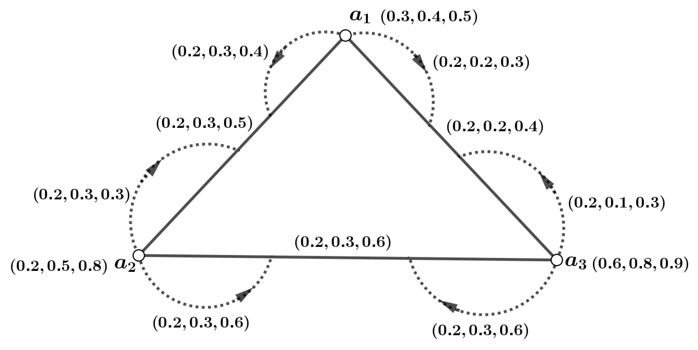
Definition 16. Let be an m-dimensional PFG, where its associated crisp graph is denoted as . Here, represents an m-PFS on W, and defines an m-PFS on . A mapping is then defined as follows:for , , and . The terms and represent the membership degree for the vertex y and the edge , respectively, in the m-PFG. The mapping ψ is referred to as the m-PFI of , while the structure is recognized as the m-PFIG. Figure 1 shows an example. Definition 17. An m-dimensional PFIG is defined as a partial subgraph of another m-dimensional PFIG if the following conditions hold for every , , and : Furthermore, is considered a subgraph of and is denoted as an m-PFIS if , , , and for all and , the equalities are satisfied.
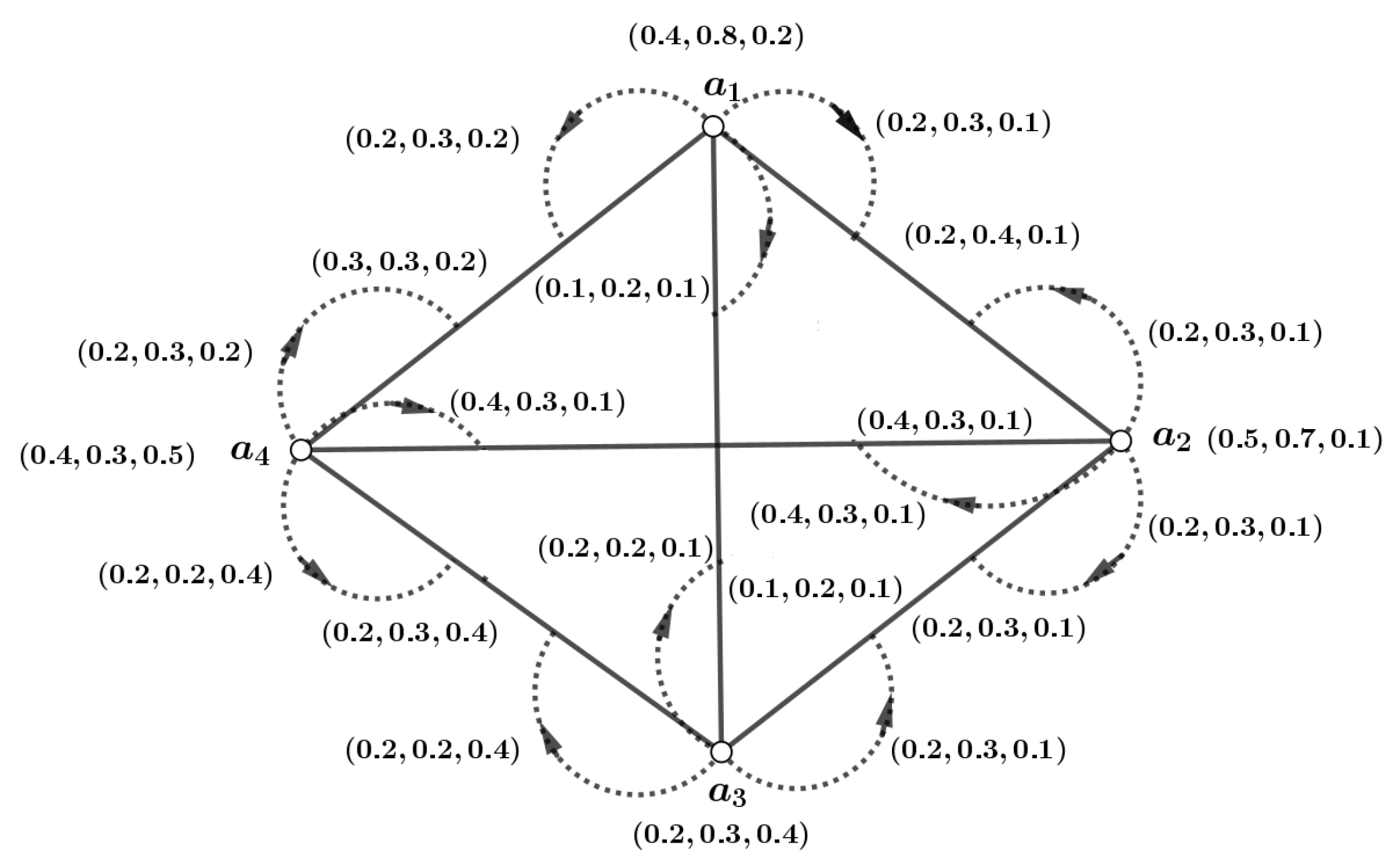
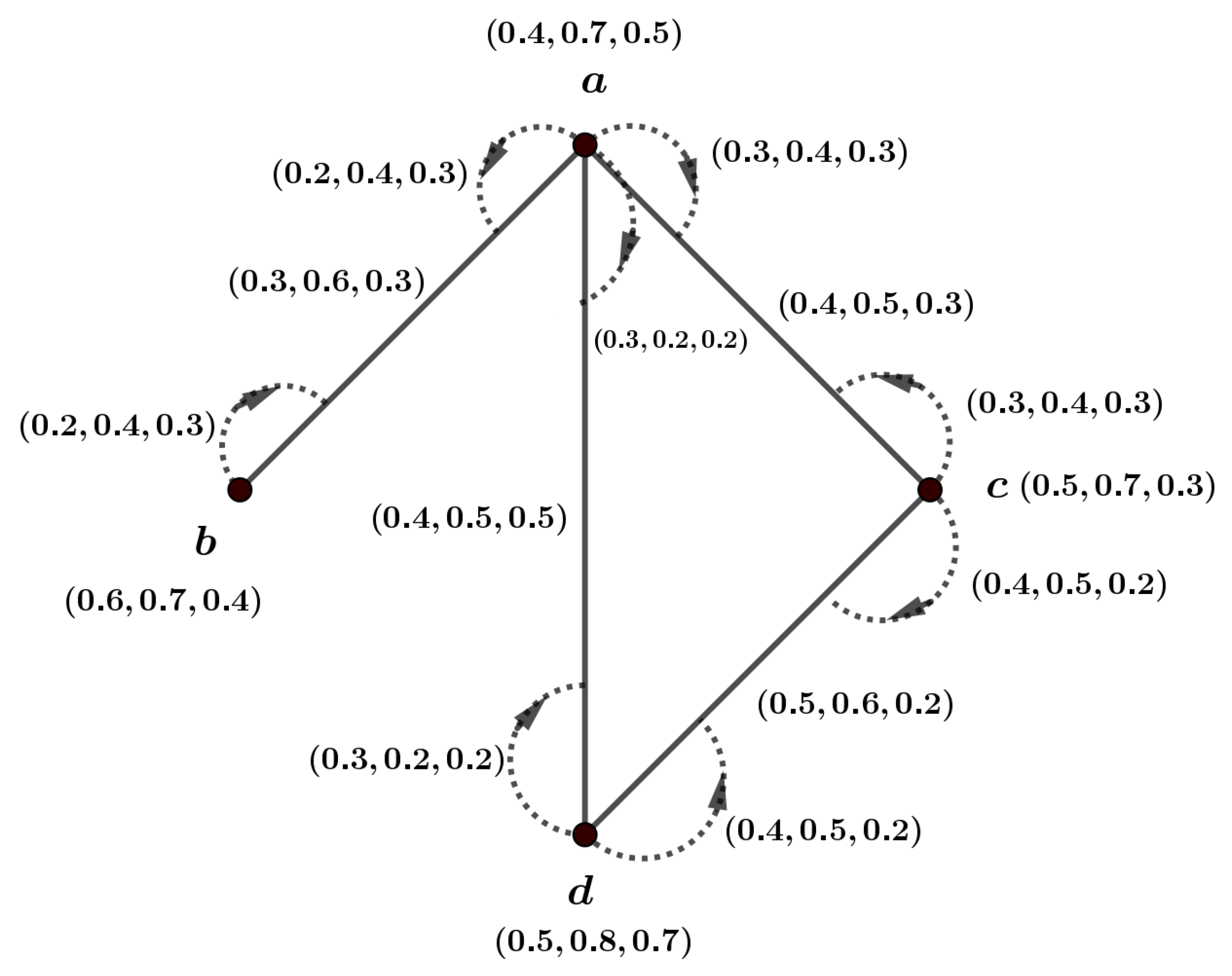
Definition 18. An m-dimensional PFIG is called a complete m-PFIG if for every vertex and for every edge , the condition holds for each . An m-dimensional PFIG is considered strong if for every edge , the condition is satisfied for all . If is a complete m-PFIG and the vertices and are adjacent at the edge , then the following holds: for all . Figure 2 describes an example. Theorem 1. A complete m-PFIG is also classified as a strong m-PFIG.
Proof. Let be a complete m-PFIG, and consider as a pair in . For all and , it follows that for each . Consequently, this implies that holds for all pairs in and for each . Therefore, qualifies as a strong m-PFIG. □
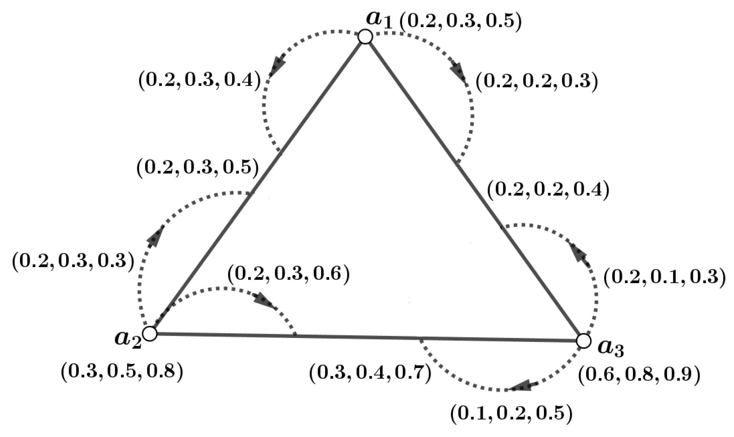
Definition 19. Let and represent the n vertices in an m-dimensional PFIG . An incidence path in can be described as follows: The IS of this path is denoted as and is represented by the expression: The ISC between x and in is represented as , given by the following expression: Example 1. Consider the connected m-PFIG illustrated in Figure 3. Here, . Now, we have, for , , . In general, , . Definition 20. Let denote an edge in an m-dimensional PFIG . If and , then the pairs and are considered pairs. The graph is said to be connected if there exists an incidence path that connects every pair of vertices.
Theorem 2. Let be an m-dimensional PFIG, and let be an m-dimensional PFIS of . For any pair in and , it holds that Proof. Consider as a subgraph of the m-dimensional PFIG . According to the definition of an m-dimensional PFIS, we have for every pair in . The terms and may correspond to the same incidence pair in both and ; otherwise, they may refer to different pairs in these graphs. This situation leads us to consider two distinct cases. □
Case 1. Assume that
and
are associated with the same pair
in both
and
. Based on the definition of an
m-dimensional PFIS, we have
. Consequently, it follows that
Case 2. Let us consider that
and
correspond to the pairs
in
and
in
. This indicates that both pairs
and
exist within
. If
, it follows that
Again, if
, then it leads to
, meaning that either
or
But, we cannot accept
because it violates the fundamental property of fuzzy subgraph mappings. Therefore, in all situations,
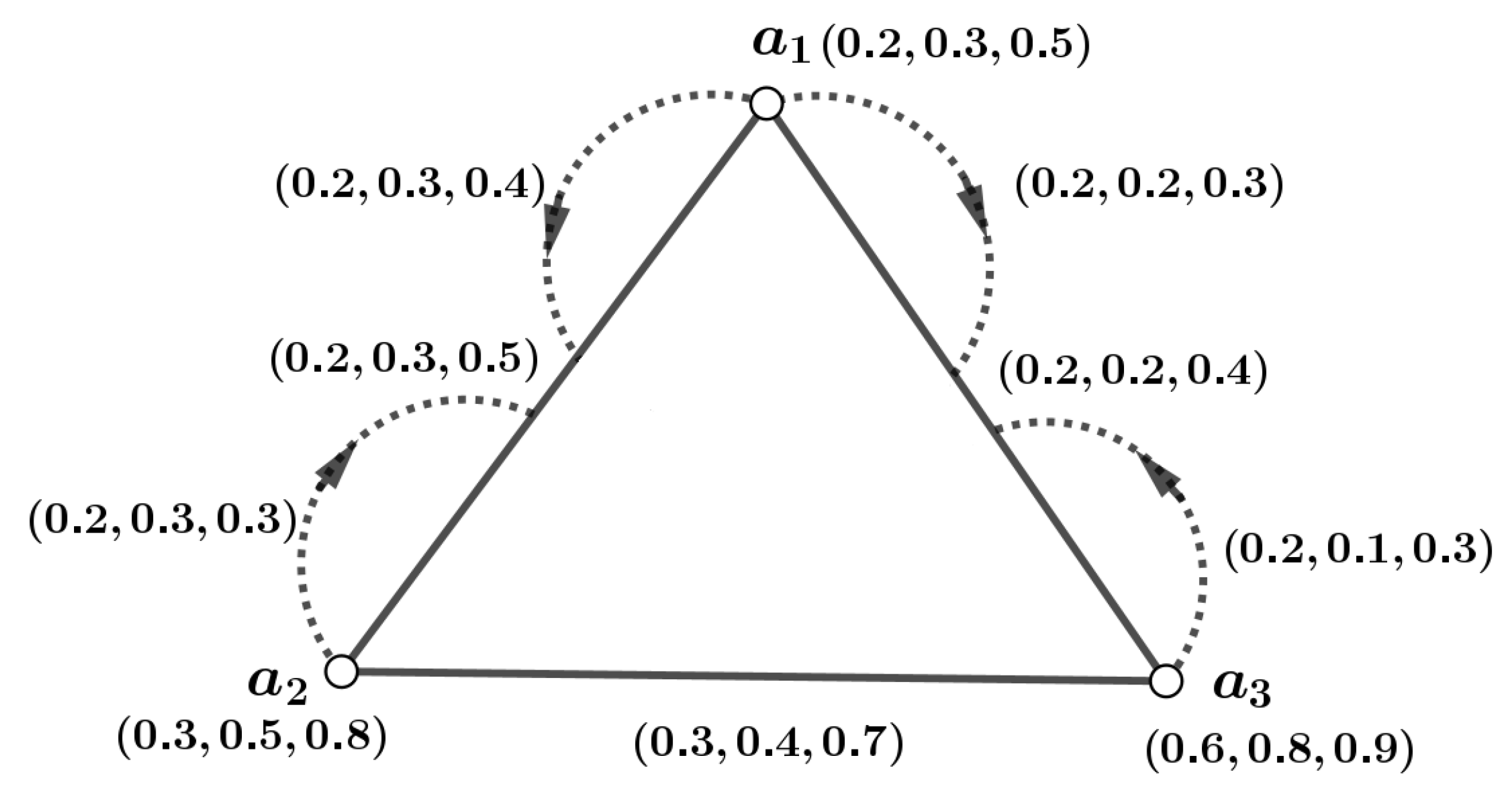
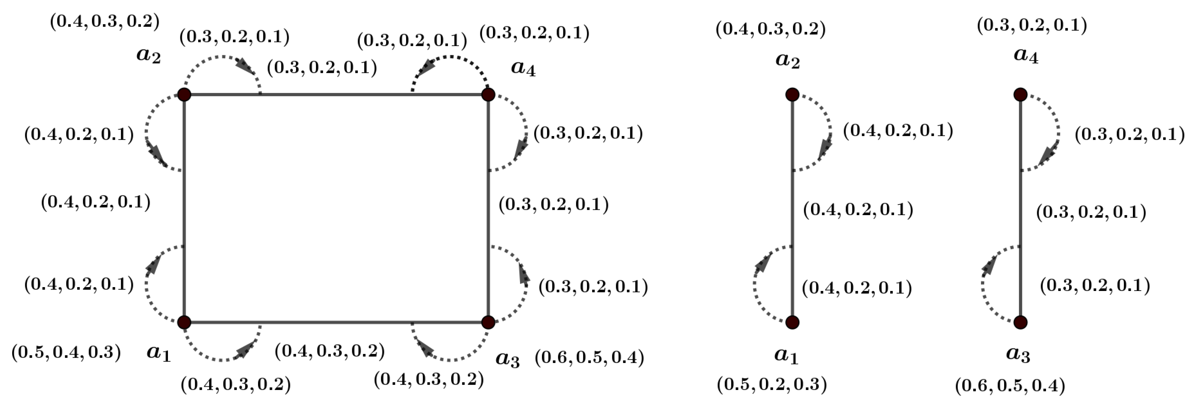
Example 2. In Figure 4 we consider as the m-PFIS of the graph of Figure 3. Now, and . Therefore, Definition 21. A pair in is considered a strong pair if .
Example 3. From the m-PFIG of Figure 5 we have, , , , , , , is not strong pair but is a strong pair. Theorem 3. In a complete m-PFIG, every edge forms a strong pair.
Proof. Consider as an m-PFIG, and consider the pair in . We have . According to the previous theorem, this establishes that is identified as a strong pair in . Since is chosen arbitrarily from the complete m-PFIG , it can be inferred that every pair in qualifies as a strong pair. □
Definition 22. Let denote an m-PFIG, and let represent an m-PFIS of . This subgraph is defined such that for every pair in ψ, it holds that . If for a particular pair in ψ, then the pair is referred to as an incidence cut pair of .
4. Matching Idea on -PFIG
Some fundamental definitions are covered in this chapter, such as support for m-PFIGs, the degree of incidence pairs, the degree of vertices, and the degree of edges in m-PFIGs, as well as the path, strength, connectedness strength, matching, MPN, MMPN, instances, and theorems.
, , and represent the sets of vertices, edges, and incidence pairs, respectively, in this section. Assume that the graph is a crisp graph. Two edges in a graph are said to be adjacent if they share a common vertex and non-adjacent if they do not share any common vertex. A collection of pairwise edges that are non-adjacent is referred to as matching.
If a matching covers every vertex in the crisp graph G, it is referred to as a perfect matching. If a matching covers the highest number of vertices, it is termed a maximum matching. A crisp graph G is considered to have a nearly perfect matching if just one vertex remains unmatched. The matching number, denoted as , refers to the total count of edges present in the maximum matching. Edges that alternate between and F are referred to as a track.
Definition 23. If is the m-PFIG, then represents the support of m-PFIG and is defined as follows:
,
,
,
Definition 24. Let the m-PFIG be . If there is a path from to such that , then two vertices and are said to be connected. An edge and a vertex are considered connected if there is a path connecting them that appears to be the following:
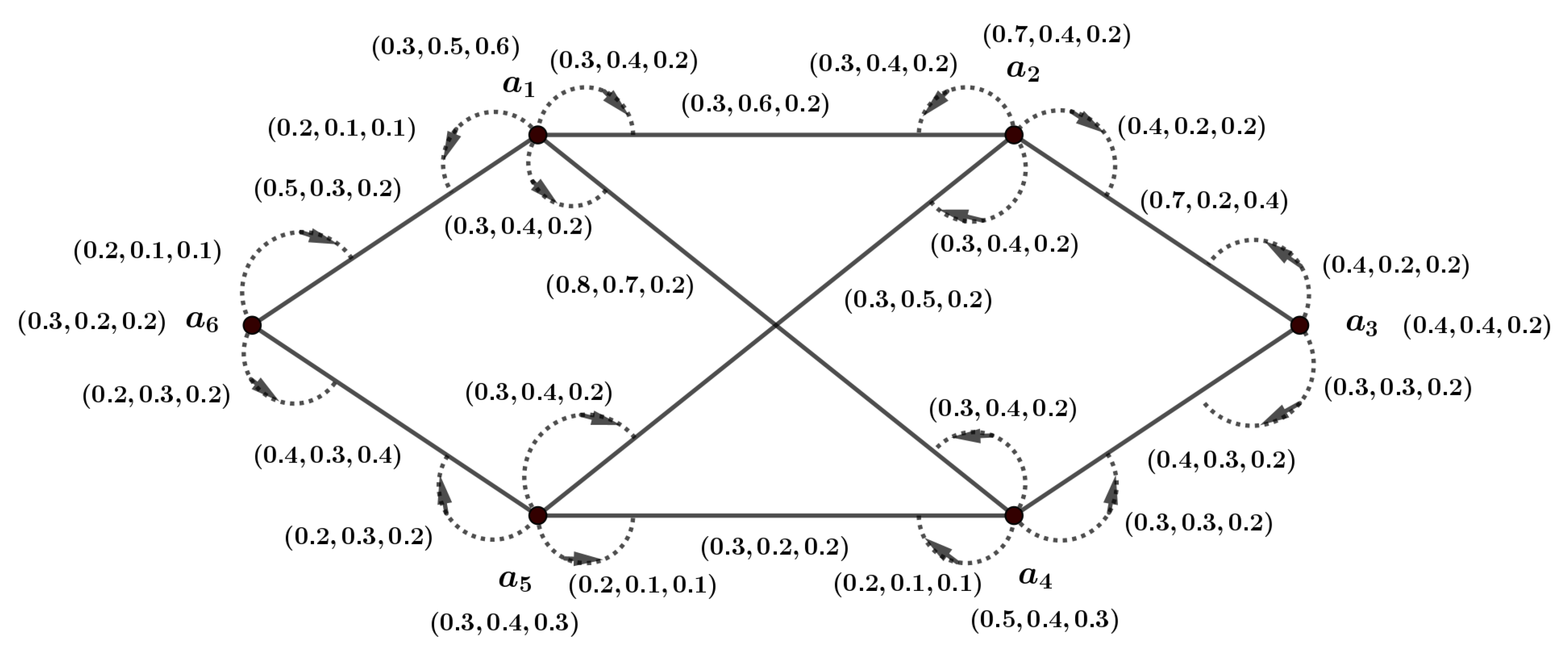
Definition 25. Assume that the m-PFIG is . Subsequently, , any vertex in has the degree defined as follows: In , the degree of an edge , where and , is as follows: In , the degree of any incidence pair where and is defined as follows: Example 4. The m-PFIG depicted in Figure 6 is examined. The degree of incidence pairs, edges, and vertices will also be calculated. The following is the degree of distinct vertices: , , , . The degree of the edges is given as follows: , , , . Likewise, the degree of different pairs of incidence are provided as follows: Definition 26. represents the strength of connectedness between in the m-PFIG, where is the highest strength of each path between and , respectively.
In this study, represents the strength of a path, and represents the strength of connectedness . It is equivalent to to have the set of vertices, edges, and incidence pair , , and , where is a matching of . The notation indicates the set that contains all matchings within . If W is equivalent to , then is a covering matching.
Definition 27. Consider the m-PFIG represented as , with a subgraph denoted as . This subgraph is defined as a matching in if, for every , there exists exactly one such that and .
Example 5. Observe an m-PFIG with a single possible matching, as shown in Figure 7. In this m-PFIG, we have: , , and . Corollary 1. Let us consider the m-PFIG represented by . A matching in induces any matching in .
Proof. Since a set of triples like
is considered a matching, we need to clearly indicate the vertices and incidence pair. Thus, as seen in
Figure 7, a matching
M can be expressed as
. □
Proposition 1. Let be the m-PFIG. Assuming that corresponds to , then , for all .
Proof. Let . A path that connects and is equivalent to a single incidence pair and ; otherwise, we have . Therefore, for each case. □
Theorem 4. Let us consider the m-PFIG represented by containing a matching . Then, and for every and .
Proof. As for every , there is only one such that ; we get: and − − = 0. □
Definition 28. In m-PFIG , let be a matching. subsequently:
- (i)
The corresponding m-PFIN of can be explained as follows: - (ii)
The definition of the matching edge m-PFIN of is as follows: - (iii)
The corresponding vertex m-PFIN of can be explained as follows: - (iv)
The corresponding crisp number of can be explained as follows:
The crisp number in a matching for an m-PFIG is the cardinality (count) of the matching set, i.e., the number of distinct, non-overlapping edges selected in the matching, ignoring the m-polar membership values. Even though each edge has multiple fuzzy components, the crisp number only reflects how many matches exist.
The terms , , and are regarded as the Matching m-Polar Fuzzy Incidence Principal Numbers (MmPFIPNs) associated with .
Example 6. Figure 7 shows an m-PFIG with a possible matching. MBFIPNs can be obtained as , , and . Definition 29. In an m-PFIG , let be a matching. Then:
- (i)
It is possible to describe the MMm-PFIN of as follows: - (ii)
The corresponding MMEm-PFIN of can be obtained as follows: - (iii)
The corresponding MMVm-PFIN of can be defined as follows: - (iv)
The following defines the MMCN of :
, , and are regarded as MMm-PFIN, MMVm-PFIN, and MMCN, respectively. There are several matchings with the same MMCN in classical graph theory. We can differentiate them using fuzzy values in the fuzzy sense.
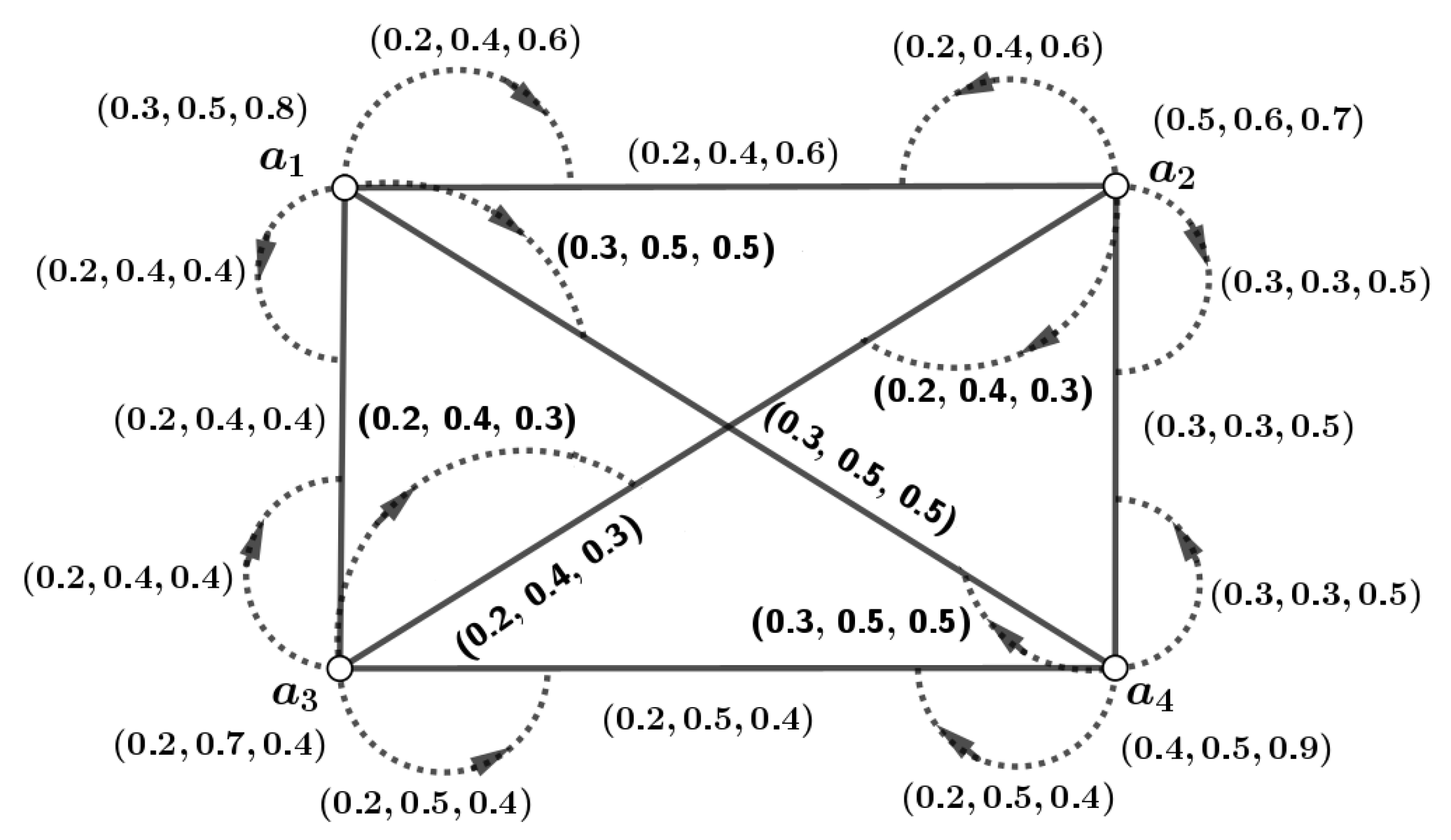
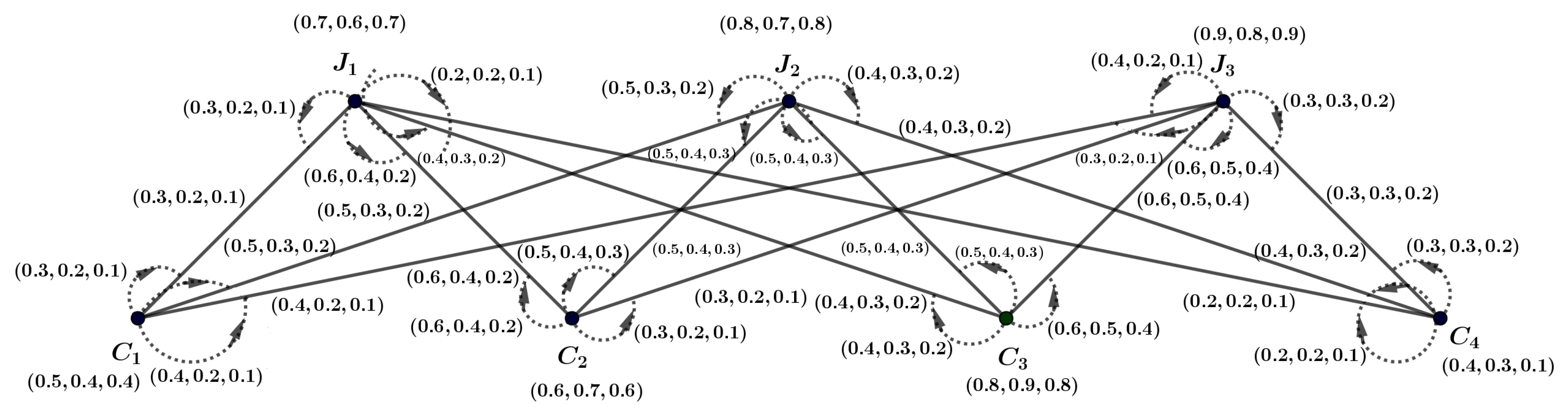
Example 7. Figure 8 shows an mPFIG . We will now determine all possible matchings—MmPFIPNs, MMmPFIN, MMVmPFIN, and MMCN—for Figure 8, as shown in Table 2. As a result, calculating the following figures is straightforward: , ,
Proposition 2. In m-PFIG , let be a matching. We therefore have the following for each and : Proof. Let
. As
is an
m-PFIG,
and
for all
and
. So, we have:
□
Definition 30. With a matching , let be an m-PFIG. An -alternating track with distinct nodes is an m-polar fuzzy -augmenting track (AT) in . The following follows: , where , , Neither nor are in .
Corollary 2. Consider as an m-PFIG that includes an -AT P within its structure. The related crisp graph similarly uses P as a -AT in this instance.
Proof. Let be an m-polar fuzzy incidence graph (m-PFIG) associated with . Suppose P is an m-polar fuzzy incidence -alternating trail, and let denote their symmetric difference (SD). The resulting set forms a matching, as it consists of a group of incidence pairs that are mutually nonadjacent and ensures that holds for every . □
Theorem 5. Let be an m-PFIG containing a matching . If the m-PFI -AT is P, then Proof. An
m-PF
-AT is represented by
P. Definition 30 is used to obtain the following:
We now have the following using Definition 28:
Consequently, we obtain the following:
□
Theorem 6. The m-PFIG has a corresponding matching with MMVmPFIN. Then, MMCN is present in .
Proof. Let be an m-PFIG that includes a matching with MMVmPFIN. To establish that contains the maximum number of incidence pairs, it is sufficient to demonstrate this property. Since is a matching in the corresponding graph , the presence of an -AT P implies that, by applying the SD, increases the MVmPFIN, as supported by Theorem 5. Thus, the requirement for the maximum number of incidence pairs is satisfied. Consequently, in a matching with MMVmPFIN, an MMCN is present. The Berge theorem states that contains the maximum possible number of edges, provided that no -AT exists. □
Remark 1. Since an m-Polar Fuzzy Incidence Covering Matching (m-PFICM) encompasses all the vertices of an m-PFIG, it follows that every m-polar fuzzy covering matching satisfies MMVm-PFIN.
Corollary 3. Consider as an m-PFIG that includes an m-polar fuzzy incidence covering matching (). In this case, satisfies MMVm-PFIN.
Proof. Let be an m-PFIG. If no -AT exists, then at least one matching must be present. The Berge theorem states that, in the absence of an -AT, contains the maximum possible number of edges. Consequently, it must satisfy MMVm-PFIN. □
Definition 31. Let be an m-PFIG. Consider any two vertices . The vertex is said to be m-PFI prior to precisely when . This relationship is represented as .
Let be an m-PFIG with two matchings, and , such that . The matching is considered m-PFI prior to if and only if .
Let be the set containing all possible matchings in that have MMCN. A matching is defined as an m-PFI strong vertex matching if it satisfies for all .
Proposition 3. Let be the m-PFIG. If a m-PFI strong vertex subgraph in is denoted as , then Proof. From
, consider
. The MMCN is admitted by any
according to Theorem 6. Thus, applying the m-PFI strong vertex matching definition, we have
Hence,
□
Definition 32. Assume that the m-PFIG is . A graph is considered a BmPFIG if it is possible to partition τ into two subsets, and , that are distinct, where every edge exclusively links a vertex from to one in or vice versa.
Remark 2. The spanning graph of is every perfect matching of . In order to find matchings using MmPFIPNs, we aim to establish pseudo-fuzzy limitations for the BmPFIG, which will be applied across different approaches.
Definition 33. Let the BmPFIG be represented by . Two subsets, and , are generated from the vertex set τ by partitioning τ, such that . We define the pseudo m-PFI restrictions for as follows:and , The pseudo mPFI constraints for are similarly regarded as follows: Theorem 7. Let the pseudo m-PFI restrictions and of the BmPFIG have two matchings, and , where represents the set of vertices. Then, a new matching exists, which matches all the vertices covered by and .
Proof. Let a BmPFIG be denoted as . Also, assume that and . There will be a matching that covers the entire set if there is a matching in that fully contains A and another matching that fully encompasses B. Therefore, if in the pseudo-fuzzy limitations and of BmPFIG , with as the set of vertices, contain two matchings— and , respectively—then there will be a new matching , which will match all the vertices covered by and . □


 ,
, 
