Article

Self-Coupling PID Control with Adaptive Transition Function for Enhanced Electronic Throttle Position Tracking

1
College of Electrical & Information Engineering, Beihua University, Jilin 132021, China
2
Intelligent Connected Vehicle Development Institute, China FAW Group Co., Ltd., Changchun 130022, China
*
Author to whom correspondence should be addressed.
Symmetry 2025, 17(5), 673; https://doi.org/10.3390/sym17050673 (registering DOI)
Submission received: 4 April 2025 / Revised: 22 April 2025 / Accepted: 25 April 2025 / Published: 28 April 2025
(This article belongs to the Special Issue Symmetry/Asymmetry of Applications in Automation and Control Systems)

Abstract

:
The objective of this study was to enhance the tracking effectiveness of the position adjustment for the electronic throttle in electric vehicles, as well as boost fuel efficiency and the dynamic performance of the vehicles. Firstly, a mathematical model, which pertains to the electronic throttle system, is established, and subsequently, the nonlinear uncertain system is made into a linear uncertain system. Subsequently, a self-coupling PID control law is designed, and an analysis is conducted on the system’s stability and its capacity to reject disturbances. Secondly, taking into consideration that the parameters of the PID controller with self-coupling mechanism are related to the system’s response speed, disturbance rejection capability, and overshoot, a self-adjusting speed factor transition function is put forward to address the conflict between speed and overshoot. Finally, numerical simulations and experimental tests are carried out. The results verify that, compared with the conventional PID controller, ADRC (Active Disturbance Rejection Control), and fuzzy PID, the proposed controller has a faster response speed, higher control accuracy, and better robustness.

1. Introduction

The nonlinear and uncertain characteristics of electronic throttle pose challenges to high-performance trajectory tracking control, and many scholars have conducted research on complex system control strategies using electronic throttle as the controlled entity. A model-based PID controller design method was presented for the nonlinear factor [1], but the nonlinear characteristics of the model are ignored; a nonlinear controller was proposed based on the backstepping method [2], but due to the need to derive the virtual control law, there may be a differential explosion problem; A sliding mode control method relying on the adaptive model was presented [3], which is complex and computationally expensive; a control method was proposed based on particle swarm identification and disturbance observer [4], which depends on the performance of the observer. Aiming at addressing the uncertainty factor, a robust filtering approach was presented to offset the model’s uncertainty [5], but the membership function and filter design are difficult; an adaptive integration terminal sliding mode technology was applied to deal with uncertainty [6], but sliding-mode chattering still exists; and an adaptive backstepping technology was used to enhance the robustness of the system [7], but there is still the problem of differential explosion. A variable structure algorithm is proposed for model tracking [8], but the tracking accuracy is slightly lower. A predictive control was proposed [9], but the construction of the error system containing the target signal is complex. An electronic throttle control system was proposed based on anti-disturbance [10], but the controller parameter tuning is difficult. In the context of state constraints and uncertain parameters, an adaptive constrained control strategy was developed [11]; however, it needs to construct an asymmetric barrier Lyapunov function. Given the utilization of an extended state observer, a tracking control method of robust adaptive dynamic sliding mode was proposed, which compensates for the total disturbance caused by nonlinearities and uncertainties of the springs due to friction and backlash through an extended state observer [12], but the performance of the system depends on the observation accuracy of the observer. At present, some scholars have conducted Q-learning research on high-performance control, path planning, trajectory tracking, and other issues in nonlinear uncertain systems [13]: a fuzzy Lyapunov reinforcement learning control strategy was proposed for nonlinear systems based on genetic algorithm optimization, which improves the stability and tracking performance of complex systems [14]; and a robotic arm control based on stochastic genetic algorithm-assisted fuzzy Q-learning was proposed to improve trajectory tracking performance [15], but these methods have a long learning time and are prone to local convergence. In addition, due to the difficulty in accurately describing the internal mechanism of the system, modern control theories based on models are limited in practical engineering applications. PID control still occupies a dominant position in practical engineering applications. However, the traditional PID control has problems such as poor robustness and the arithmetic operations that violate the dimension attribute. The strategy set forth in this paper aims to improve the traditional PID control algorithm, starting from the physical properties.
This paper focuses on the transition process, stability control, and high-precision tracking requirements of nonlinear uncertain electronic throttle servo systems. A control algorithm for electronic throttle systems utilizing self-coupling PID is proposed, and stability and disturbance rejection analyses are conducted. Simulation experiments are compared with fuzzy PID and ADRC. Finally, prototype experiments are conducted to demonstrate the efficiency of the presented control tactic.
The major contributions are as follows: (1) Transformation of nonlinear uncertain systems: By defining the system dynamics and cumulative disturbances from internal and external uncertainties, we transform nonlinear uncertain systems into linear uncertain systems. This approach diminishes the distinctions between linear and nonlinear, as well as time-varying and time-invariant systems. Additionally, an error dynamic system driven by the cumulative disturbance is constructed to enhance system immunity. (2) Self-coupling PID strategy: To address the contradictory issues of “dimensional conflict” and “uncoordinated control mechanism” in PID control, we propose a self-coupling PID strategy. This strategy uses the velocity factor as the core connection element, effectively resolving the significant problems of poor gain robustness and disturbance resistance in PID control systems. (3) Adaptive speed factor design: To improve the performance of the transition process, we design an adaptive speed factor. This design specifically targets the mitigation of overshoot and oscillation during the initial dynamic response stage, thereby enhancing overall system performance.

2. Electronic Throttle Model

The electronic throttle system of an automobile includes the throttle body and the electronic controller. The throttle valve comprises a DC motor, reduction gear set, throttle flap, return spring, and displacement sensor [4]. The structure of the throttle valve is illustrated in Figure 1.
According to the Kirchhoff voltage law, the armature loop equation of the DC motor can be obtained as follows:
u a = R i a + L d i a d t + e a
e a = k e θ m
T m = k m i a
where e a is the back EMF of the armature, u a is the applied voltage for the armature, i a is the current through the armature winding, R is the equivalent resistance of the armature circuit, L is the armature circuit’s equivalent inductance, k e is the back EMF coefficient, θ m is the motor’s rotation angle, ω m is the motor’s rotational speed, k m is the electromagnetic torque coefficient, and T m is the motor’s output torque.
Since L is very small, it can usually be ignored. Equation (1) can be simplified as follows:
u a = R i a + e a
According to the principle of torque conservation, the dynamic equation is obtained as follows:
J m θ · · m = T m k c θ · m T i
where J m is the moment of inertia of the rotor of the DC motor, T l is the load torque, and k c is the motor shaft’s viscous coefficient. The equation that describes the motion of the throttle flap is
J g θ · · = T g T s p T t f T a f
where J g is the inertia moment of the throttle flap, T s p is the spring torque, T a f is the aerodynamic torque, T g is the torque conveyed from the gear to the flap, T t f is the frictional torque, and θ is the flap’s position.
The relationships between the spring torque ( T s p ), the nonlinear friction ( T t f ), and the opening degree of the throttle flap are as follows:
T s p = k s p ( θ θ 0 )
T t f = k t f sgn θ ˙ + k f θ ˙
According to the gear ratio relationship, n = θ m θ = T g T l , the mathematical model of the gear set is
T g = n k m i a n 2 J m θ ¨ n 2 k c θ ˙
i a = u a R n R k e θ ˙
θ ¨ = 1 n 2 J m + J g [ k s p ( θ θ 0 ) k t f sgn θ ˙ + n k m u a R ( n 2 k c + k f + n 2 R k m k e ) θ ˙ ] T a f n 2 J m + J g
The above model does not take into account changes in motor parameters, spring parameters, etc. Therefore, the control challenge for the electronic throttle is to ensure that, in the presence of unmodeled dynamics and unpredictable external disturbances, the position response of the electronic throttle can exhibit superior tracking performance.
To facilitate analysis and controller design, define the state variable as x = θ θ · T , the control input as u = u a , and a system output, and then the system’s state space formulated is written as follows:
x ˙ 1 x ˙ 2 = 0 1 k s p J a x 1 x 2 + 0 n k m J R u + 0 b x 2 + 0 1 d 0 y = x 1
where a = n 2 k c + k f + n 2 k e k m R J , J = n 2 J m + J g , b x 2 = k t f sgn x 2 + k s p θ 0 J , and external bounded disturbance is d 0 = T a f J .
As can be seen from Equation (11) or Equation (12), the electronic throttle’s mathematical model is a second-order nonlinear uncertain system. To facilitate the design of the controller, it is necessary to carry out an equivalent transformation of the mathematical model.

3. Design of Electronic Throttle Controller

Write Equation (12) as a second-order nonaffine nonlinear uncertain system [16].
x ˙ 1 = x 2 x ˙ 2 = f ( x 1 , x 2 , u ) + d 0 y = x 1
where f x 1 , x 2 , u represents a function that is unknown and uncertain. According to Equation (13), the unknown uncertainties and the system’s external disturbances are defined as total disturbances:
d = f x 1 , x 2 , u + d 0 b 0 u
where b 0 is the control gain estimate. And then Equation (13) can be written as follows:
x ˙ 1 = x 2 x ˙ 2 = d + b 0 u y = x 1
It can be seen that Equation (15) is a second-order linear uncertain affine system equivalent to Equation (13). For the tracking control problem of the system of Equation (13), the error is e 1 = r y , and the error’s integral value is e 0 = e 1 d t , so let
e 2 = e ˙ 1 = r ˙ y ˙ = r ˙ x 2 e ˙ 2 = e ¨ 1 = r ¨ y ¨ = r ¨ d b 0
According to e 1 , e 0 , and Equation (16), the controllable error system can be obtained as follows:
e ˙ 0 = e 1 e ˙ 1 = e 2 e ˙ 2 = r ¨ d b 0 u
For the error system equation of Equation (17), in order to achieve dimensional attribute matching and achieve error closed-loop system with three identical poles, z c , based on the relationship between cubic equation roots and coefficients, the self-coupling PID control is selected as follows:
u = r ¨ + z c 3 e 0 + 3 z c 2 e 1 + 3 z c e 2 b 0
where z c is the velocity factor, 3 z c 2 is equivalent to k p of the PID controller, z c 3 is equivalent to k i of the PID controller, and 3 z c is equivalent to k d of the PID controller. The innovation of the self-coupling PID control method is firstly to combine proportion, integral, and differential to form the control quantity through z c , and secondly to take into account the second-order differential of the input signal. It can be seen that if the dimension of z c is 1/second (s − 1), the location dimension of r is meters (m), the dimension of e 1 = r y is m , the dimension of e 0 = e 1 d t is ms, and the dimension of e 2 = r · y · is ms − 1, then the dimensions of r · · , 3 z c 2 e 1 , z c 3 e 0 , and 3 z c e 2 are all ms − 2; that is, by converting the proportion, integral, and differential into the same physical dimension for addition, it is more reasonable from the dimension attribute. And also, the intrinsic relationship between the gains of e 0 , e 1 , and e 2 is established. In addition, Equation (18) has a generalized acceleration magnitude property coinciding with the magnitude property requirement of the control input, b 0 u , of any second-order system, and the block diagram of the second-order system self-coupling PID closed-loop control structure is shown in Figure 2. It can be seen that the self-coupling PID solves the problems of “quantitative conflict” and “uncoordinated control mechanism” in PID control.

4. Analysis of Stability and Disturbance Rejection of System

Theorem 1. 
Suppose that the total disturbance Equation (14) of the system is bounded, that is, d <  , then if  z c > 0  , the closed-loop control system constituted by the control quantities defined in Equation (18) is stable and has good disturbance robustness.
Proof. 
Substituting Equation (18) into error system of Equation (17), the following can be obtained:
e ˙ 0 = e 1 e ˙ 1 = e 2 e ˙ 2 = d z c 3 e 0 3 z c 2 e 1 3 z c e 2
Equation (19) is the error dynamic system under total disturbance, d ; set the initial states as e 0 0 = 0 , e 1 0 0 , and e 2 0 0 ; and then we have the following:
s e 0 ( s ) e 0 ( 0 ) = e 1 ( s ) s e 1 ( s ) e 1 ( 0 ) = e 2 ( s ) s e 2 ( s ) e 2 ( 0 ) = d ( s ) z c 3 e 0 ( s ) 3 z c 3 e 1 ( s ) 3 z c e 2 ( s )
s 3 e 1 ( s ) + z c 3 e 1 ( s ) + 3 z c 3 s e 1 ( s ) + 3 z c s 2 e 1 ( s ) = s [ s e 1 ( 0 ) + 3 z c e 1 ( 0 ) + e 2 ( 0 ) d ( s ) ]
E 1 ( s ) = ( s e 1 ( 0 ) + 3 z c e 1 ( 0 ) + e 2 ( 0 ) d ( s ) / H ( s )
Equation (21) consists of zero input response and zero state response. Here, H s is
H ( s ) = s s + z c 3
Its unit pulse response is as follows:
h ( t ) = ( 0.5 z c t 2 t ) e z c t
Then, the time domain expression of Equation (21) is as follows:
e 1 ( t ) = e 1 ( 0 ) h ˙ ( t ) [ ( e 2 ( 0 ) + 3 z c e 1 ( 0 ) ] h ( t ) + h ( t ) d ( t )
where h ˙ ( t ) = ( 0.5 z c 2 t 2 + 2 z c t 1 ) e z c t . In addition, according to e 2 = e · 1 , we have the following:
e 2 ( t ) = e 1 ( 0 ) h ¨ ( t ) [ ( e 2 ( 0 ) + 3 z c e 1 ( 0 ) ] h ˙ ( t ) + h ˙ ( t ) d ( t ) + h ( t ) d ˙ ( t )
It can be seen from Equation (22) that if z c satisfies z c > 0 , Equation (22) has three poles in the left half flap and the system exhibits asymptotic stability. It can be seen from Equations (23)–(25) that when z c > 0 , lim t 0 h ( t ) = 0 , and lim t 0 h ( t ) = 0 , then when d < , there must be lim t 0 e 1 ( t ) = 0 and lim t 0 e 2 ( t ) = 0 , that is, any initial state not zero toward the origin 0 , 0 .
From the above analysis, it can be seen that z c > 0 can ensure the stability of the system. When z c is larger, the system demonstrates a more rapid dynamic response speed and a superior capacity to withstand and counteract disturbances. However, a larger z c will lead to overshoot and oscillation in the initial dynamic response stage. A smaller z c results in less control power for proportional and integral, which not only reduces the system’s response speed but also the steady-state control accuracy and immunity to disturbances. Consequently, for the purpose of achieving no overshoot, a quick response speed, and a high level of disturbance rejection ability, the adaptive transition function, z c , is designed as Formula (26). The initial value of this function is small and gradually increases with the progress of the transition process.
z c = β [ 1 α exp ( t T d ) ]
where β is the gain coefficient, α is the attenuation coefficient, and T d is the transition time. □

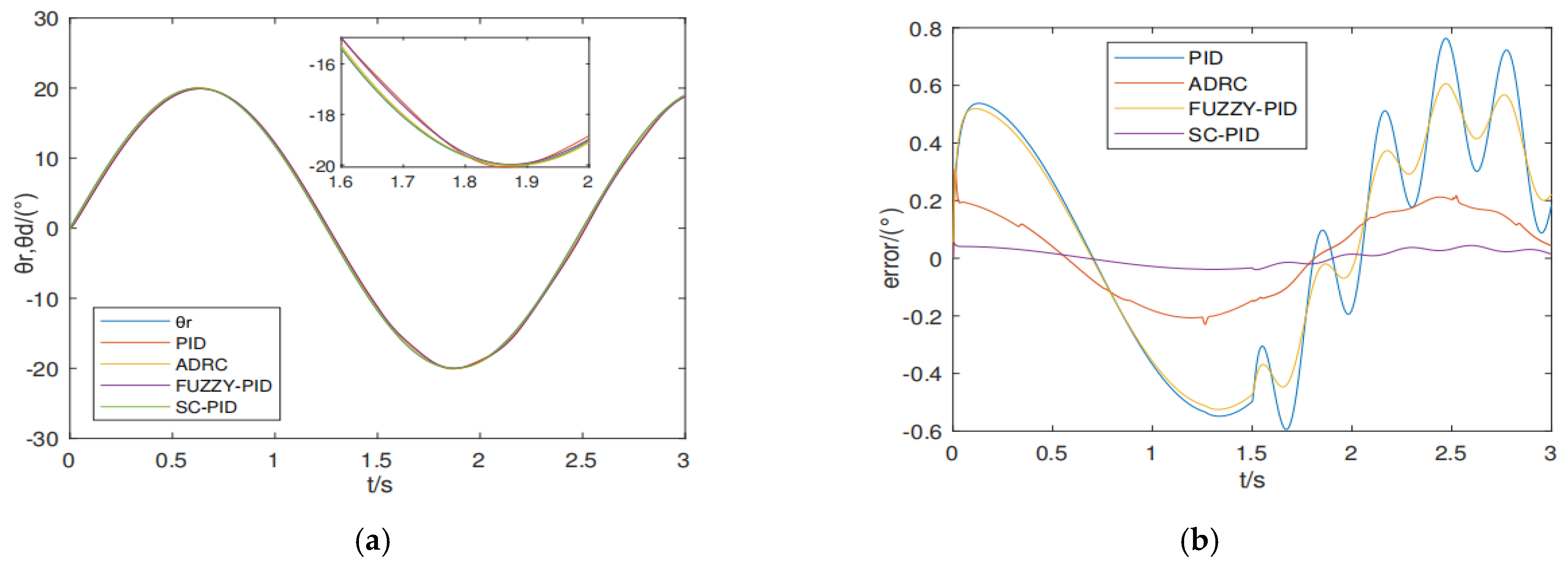
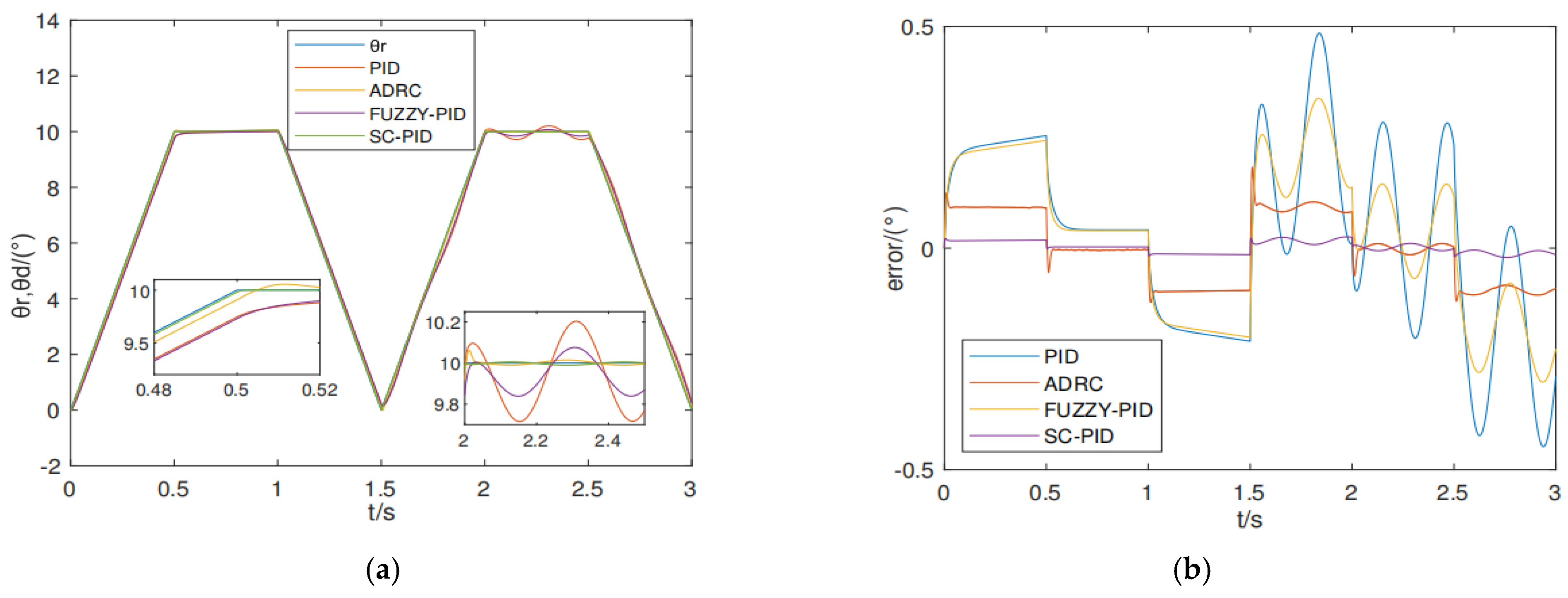
5. Comparative Simulation Experiments of Conventional PID, Active Disturbance Rejection, Fuzzy PID, and the Proposed Control Strategy

With the aim of assessing the control performance of the control strategy presented in this paper, simulation verification is performed in the MATLAB2019b/Simulink environment, and the electronic throttle used by a certain model Hongqi car of FAW is selected for simulation [2]. Table 1 summarizes its major parameters.
According to the speediness and no overshoot requirements of the electric throttle tracking control, the parameters of the adaptive transition function, z c , are selected as β = 10 , α = 0.7 , and T d = 0.025 . For the purpose of confirming the effectiveness of the control strategy put forward in this paper, the steps described below were carried out: a comparative simulation experiment was performed between conventional PID, ADRC, Fuzzy PID control, and the control strategy proposed in this paper. The parameters for the standard PID controller are, specifically, k p = 80 , k i = 0.5 , and k d = 2 . The parameters for the active disturbance rejection controller are, specifically, β 1 = 450 , β 2 = 20.5 , β 01 = 180 , β 02 = 1000 , β 03 = 20 , h = 0.01 , and T = 0.01 . The parameters for the fuzzy PID controller are, specifically, k p 0 = 75 , k i = 0.4 , and k d = 1.5 . Finally, prototype experiments were conducted.
Figure 3, Figure 4 and Figure 5 represent the expected angle of the throttle valve for step signal θ r = 60 , sine signal θ r = 20 sin 0.4 t , and trapezoidal signal θ r = 20 t , t < 0.5 10 , 0.5 t < 1 10 20 ( t 1 ) , 1 t < 1.5 , respectively. And at t = 1.5   s , we introduce a disturbance signal, f ( t ) = 5 sin ( 20 t ) . Response curves and error curves are for conventional PID control, active disturbance rejection control, fuzzy PID control, and the proposed control strategy.
The position tracking response curve and the error curve are obtained in Figure 3 when a disturbance, f ( t ) , is added, with the expected value being a step signal. The performance indicators of the four control methods are summarized in Table 2. The results indicate that the proposed control strategy has a fast response to the step signal and a small tracking error for the periodic disturbance.
The position tracking response curve and the error curve are displayed in Figure 4 for when a disturbance is added, with the expected value being a sinusoidal signal. The performance indicators of the four control methods are summarized in Table 3. The result indicated that the proposed control strategy has small amplitude and phase errors in tracking the sinusoidal signal and has good disturbance rejection performance.
Figure 5 shows the position tracking response curve and the error curve when disturbance, f ( t ) , is added, with the expected value being a trapezoidal signal. The performance indicators of the four control methods are shown in Table 4. The results indicate that the proposed control strategy has good tracking accuracy and the ability to resist external disturbances for the trapezoidal signal.

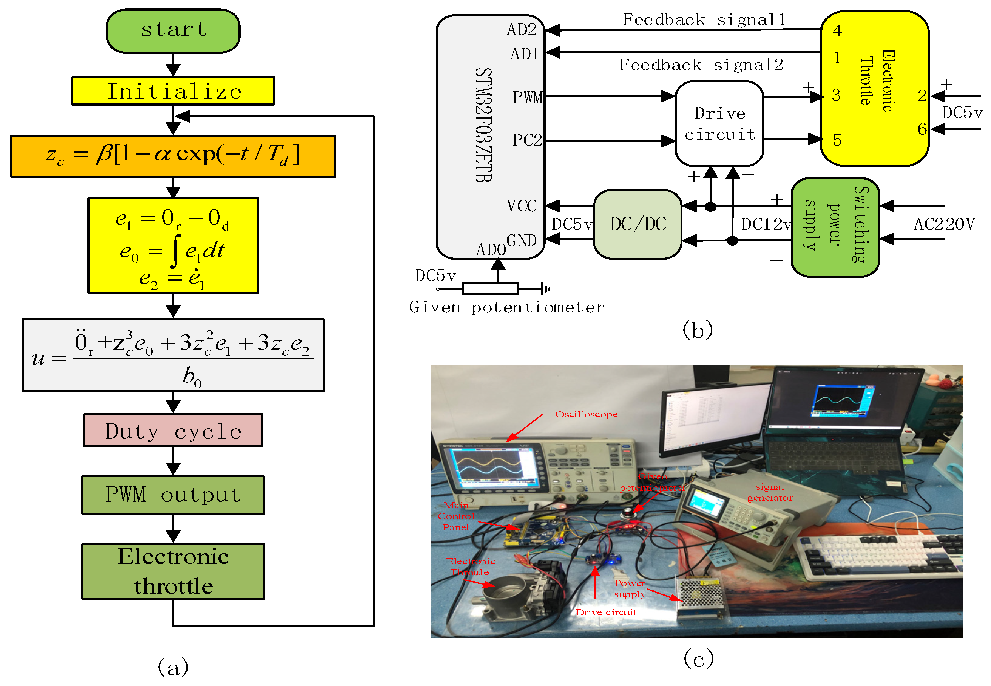
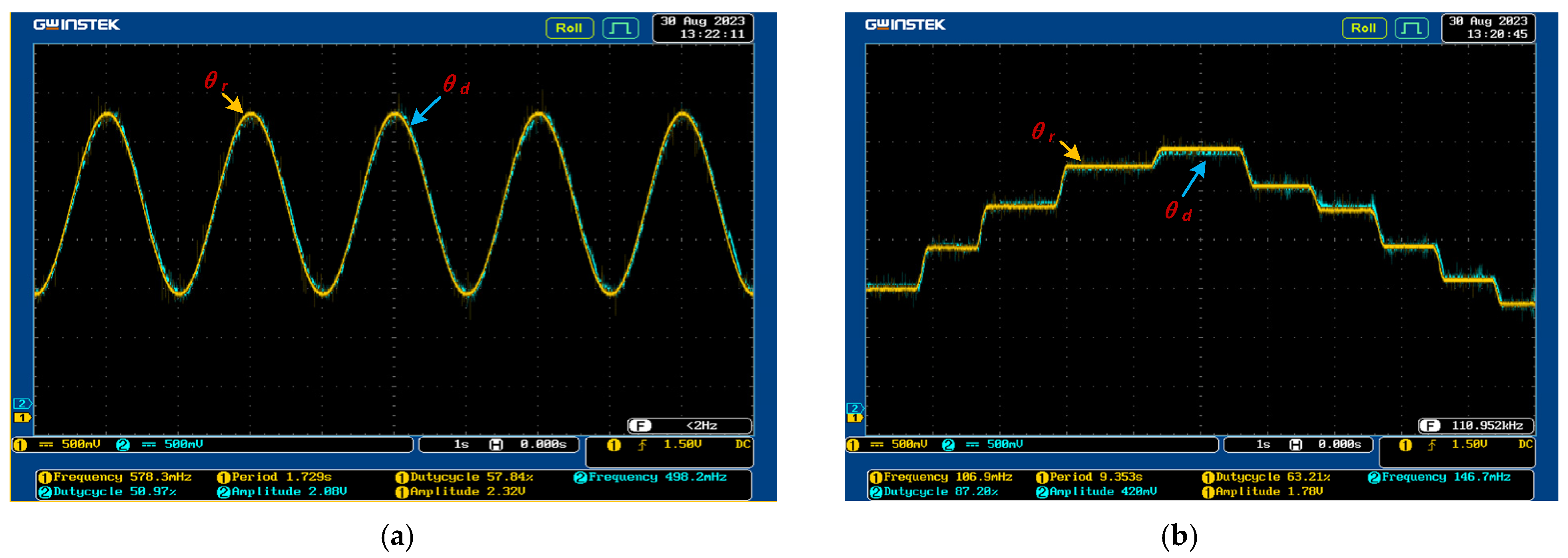
6. Prototype Experiment

An experimental platform was constructed based on the theoretical analysis depicted in Figure 6a,b. Figure 6c shows that the experimental prototype comprises a main control board (STM32F03ZETB), power supply, and drive circuit.
The control algorithm process is as follows:
Step 1: Set the parameters of the controller: β , α , T d , and b 0 .
Step 2: Obtain Z c .
Step 3: Calculate the deviation, e 1 ; integral, e 0 ; derivative, e 2 ; and θ ¨ r .
Step 4: Calculate the control quantity, u , and convert it into a duty cycle.
Step 5: Output PWM pulses to control the throttle motor voltage.
We must take into account that the actual operation of the vehicle accelerator pedal will not lead to an abrupt step change, meaning that there is no sudden jump in the desired trajectory of the throttle valve. In this paper, a sinusoidal signal and a trapezoidal wave signal are employed to mimic the desired trajectory of the throttle valve for the purpose of conducting a position-tracking performance test.
From Figure 7, when the input signal is sinusoidal and step signal, the control strategy proposed in this paper can realize stable control, the error of tracking sinusoidal signal is less than 0.05, the error of tracking step signal is less than 0.03, and the response time of the system is less than 100 ms, which can satisfy the requirements of the actual control indexes of the servo system of the automotive electronic throttle.

7. Conclusions

This paper focuses on the electronic throttle valve and presents a self-coupling PID control method to meet the control performance requirements. An adaptive velocity factor function is designed, and a comprehensive dynamic system of disturbance errors is constructed. Comparative simulation experiments are conducted with PID, fuzzy PID, and ADRC. On the basis of the experiments, the following conclusions can be drawn:
(1)
The self-coupling PID control law enables the throttle valve opening to track the target signal quickly, accurately, and without overshoot. It also exhibits good robustness.
(2)
The adoption of the adaptive transition function effectively addresses the trade-off between speed and overshoot. The self-coupling PID control method is easier to tune compared to conventional PID, fuzzy PID, and ADRC.
(3)
By transforming the closed-loop control system of a nonlinear uncertain system into an error dynamic system under comprehensive disturbance excitation, and analyzing the system performance using pulse excitation response, a new approach is proposed for nonlinear control, which is easy to understand and provides a new avenue for nonlinear control exploration.
The proposed self-coupling PID controller proposed is an integer-order PID controller. However, the power supply circuit and mechanical transmission of the actual electronic throttle system have fractional-order characteristics, thus limiting the performance of the integer-order self-coupling PID controller. Therefore, the fractional-order self-coupling PID controller is an issue for further study in the future.

Author Contributions

Conceptualization, Y.C.; methodology, Y.C., C.L. and P.L.; software, Y.C. and C.L.; validation, Y.C., C.L. and P.L.; writing—original draft, Y.C. and C.L.; writing—review and editing, C.L. All authors have read and agreed to the published version of the manuscript.

Funding

The work was supported by the Department of Education of Jilin Province (grants JJKH20200044KJ, JJKH20230064KJ, and JJKH20240084KJ), the Jilin Provincial Development and Reform Commission (grant 2022C045-11), and the Beihua University Research and Innovation Project (grant [2024]016).

Data Availability Statement

Data are contained within the article.

Conflicts of Interest

Author Mr. Peilin Liu was employed by Intelligent Connected Vehicle Development Institute, China FAW Group Co., Ltd., Changchun, China. The remaining authors declare that the research was conducted in the absence of any commercial or financial relationships that could be construed as potential conflicts of interest.

References

  1. Chang, Y. Model-based analysis and tuning of electronic throttle controller. In 2004 Society of Automotive Engineers World Congress; SAE International: Detroit, MI, USA, 2004. [Google Scholar]
  2. Chen, H.; Hu, Y.F.; Guo, H.Z. Electronic throttle control based on Backstepping method. Control Theory Appl. 2011, 28, 491–496. [Google Scholar]
  3. Hashimoto, E.; Tetsuya, I.; Yasut, Y. High reliability electronic throttle system design. In 2003 Society of Automotive Engineers World Congress; SAE International: Detroit, MI, USA, 2003. [Google Scholar]
  4. Sun, Z.T.; Jiao, X.H.; Xue, J.Q. Prescribed performance control Based on PSO identification and disturbance observer for automotive electronic throttle system with actuator constraint. J. Control Eng. Appl. Inform. 2020, 22, 24–31. [Google Scholar]
  5. Yuan, X.F.; Wang, Y.N. A novel electronic throttle valve controller based on approximate model method. IEEE Trans. Ind. Electron. 2009, 56, 883–890. [Google Scholar] [CrossRef]
  6. Wang, H.; Li, Z.; Jin, X.; Huang, Y.; Kong, H.; Yu, M.; Ping, Z.; Sun, Z. Adaptive integral terminal sliding mode control for automobile electronic throttle via an uncertainty observer and experimental validation. IEEE Trans. Veh. Technol. 2018, 67, 8129–8143. [Google Scholar] [CrossRef]
  7. Wang, D.; Liu, S.; He, Y.; Shen, J. Barrier Lapunov Function based adaptive back-stepping control for electronic throttle control system. Mathematics 2021, 9, 326. [Google Scholar] [CrossRef]
  8. Jia, D.M.; Zhang, H. Electronic Throttle Control Based on Model-following Variable Structure Algorithm. Electr. Drive 2021, 51, 58–64. [Google Scholar]
  9. Zhang, B.J.; Chen, Z.; Tian, Y.; Zhang, N.; Wang, M. Optimal Preview position control for automotive electronic throttle. Nongye Jixie Xuebao 2017, 48, 349–354. [Google Scholar]
  10. Chen, F.X.; Liu, L.; Zhang, T. Control of electronic throttle based on active disturbance rejection control of technique. China Sci. Pap. 2014, 9, 1188–1191. [Google Scholar]
  11. He, Y.; Liu, X.; Wang, D.; Yuan, C.; Shen, J. Adaptive constrained control for automotive electronic throttle control system with experimental analysis. at-Automatisierungstechnik 2022, 70, 192–204. [Google Scholar] [CrossRef]
  12. Hu, Y.; Wang, H. Robust tracking control for vehicle electronic throttle using adaptive dynamic sliding mode and extended state observer. Mech. Syst. Signal Process. 2020, 135, 106375. [Google Scholar] [CrossRef]
  13. Kumar, A.; Kukker, A. Reinforcement learning-based intelligent energy management system for electric vehicle. In Intelligent Control for Modern Transportation Systems; CRC Press: Boca Raton, FL, USA, 2023; pp. 153–166. [Google Scholar]
  14. Kukker, A.; Sharma, R. Genetic Algorithm-Optimized Fuzzy Lyapunov Reinforcement Learning for Nonlinear Systems. Arab. J. Sci. Eng. 2020, 45, 1629–1638. [Google Scholar] [CrossRef]
  15. Kukker, A.; Sharma, R. Stochastic Genetic Algorithm-Assisted Fuzzy Q-Learning for Robotic Manipulators. Arab. J. Sci. Eng. 2021, 46, 9527–9539. [Google Scholar] [CrossRef]
  16. Zeng, Z.Z.; Liu, W.J. Self-coupling PID Controllers. Actor Antomatica Sin. 2021, 47, 404–422. [Google Scholar]
Figure 1. The electronic throttle system.
Symmetry 17 00673 g001
Figure 2. Structure diagram of the self-coupling PID-based closed-loop control system.
Symmetry 17 00673 g002
Figure 3. Performance with disturbance signal f t = 5 sin 20 t at t = 1.5   s for a step signal reference angle: (a) output curve and (b) error curve.
Symmetry 17 00673 g003
Figure 4. Performance with disturbance signal f t = 5 sin 20 t at t = 1.5   s for a sinusoidal reference angle: (a) output curve and (b) error curve.
Symmetry 17 00673 g004
Figure 5. Performance with disturbance signal f t = 5 sin 20 t at t = 1.5   s for a trapezoidal reference angle: (a) output curve and (b) error curve.
Symmetry 17 00673 g005
Figure 6. Implementation of experiment: (a) flowchart, (b) system composition diagram, and (c) experimental prototype.
Symmetry 17 00673 g006
Figure 7. Experimental curve: (a) tacking a sinusoidal signal and (b) tracking a trapezoidal signal.
Symmetry 17 00673 g007
Table 1. Major parameters of the electronic throttle.
ParametersValueUnitParametersValueUnit
k e 0.016 V rad / s k f 4 × 10⁻⁴ N · m rad / s
k c 1.6 × 10⁻⁶ N · m rad / s k s p 0.0247 N · m rad / s
k t f 0.0048 N · m R 2.8 Ω
θ 0 0.0349 rad J 1.15 × 10⁻³ kg · m 2
n 16.95 k m 0.016 N · m · A 1
Table 2. Performance indicators for a step signal reference angle.
Property IndexPIDFUZZY-PIDADRCSC-PID
Adjusting time (s)0.20.20.120.06
Maximum error under f ( t ) disturbance (°)0.450.340.0540.009
Table 3. Performance indicators for a sinusoidal reference angle.
Property IndexPIDFUZZY-PIDADRCSC-PID
Tracking error without disturbance (°)0.50.50.20.03
Maximum error under f ( t ) disturbance (°)0.70.60.20.044
Table 4. Performance indicators for a trapezoidal reference angle.
Property IndexPIDFUZZY-PIDADRCSC-PID
Tracking error without disturbance (°)0.250.240.110.017
Maximum error under f ( t ) disturbance (°)0.470.330.170.02
Disclaimer/Publisher’s Note: The statements, opinions and data contained in all publications are solely those of the individual author(s) and contributor(s) and not of MDPI and/or the editor(s). MDPI and/or the editor(s) disclaim responsibility for any injury to people or property resulting from any ideas, methods, instructions or products referred to in the content.

