Article

A Composite Linear Active Disturbance Rejection Control-Sliding Mode Control Strategy with Nominal Model Compensation for Precision Motion Tracking in Semiconductor Die Attach Machines

1
State Key Laboratory of Climate System Prediction and Risk Management/Key Laboratory of Meteorological Disaster, Ministry of Education/Collaborative Innovation Center on Forecast and Evaluation of Meteorological Disasters, Nanjing University of Information Science and Technology, Nanjing 210044, China
2
School of Atmospheric Sciences, Nanjing University of Information Science and Technology, Nanjing 210044, China
3
Wuxi Autowell Technology Co., Ltd., Wuxi 214000, China
4
School of Automation, Wuxi University, Wuxi 214105, China
5
School of Automation, Nanjing University of Information Science & Technology, Nanjing 210044, China
*
Author to whom correspondence should be addressed.
Symmetry 2025, 17(5), 636; https://doi.org/10.3390/sym17050636
Submission received: 19 March 2025 / Revised: 12 April 2025 / Accepted: 14 April 2025 / Published: 23 April 2025
(This article belongs to the Section Engineering and Materials)

Abstract

:
In this paper, the concept of symmetry is utilized to design the composite controller for the die attach machine’s motion platform—that is, the construction and the solution of the nominal model-based composite controller design approach are symmetrical. With escalating demands for ultra-high-speed operations and microscale positioning accuracy (<5 μm) in semiconductor manufacturing, motion platforms face critical challenges, including high-speed instability, positioning jitter, and insufficient disturbance rejection. To address these limitations, a composite control strategy integrating nominal model-based linear active disturbance rejection control (NMLADRC) with sliding mode control (SMC) is developed. The synergistic interaction ensures the concurrent realization of robust tracking accuracy and rapid transient convergence. Simulation results demonstrate significant improvements over conventional PI control, LADRC, and NMLADRC. The phase lag is reduced by 50.04%, 36.34%, and 23.07%, respectively, while positioning time within ±5 μm accuracy threshold is shortened by 44.00%, 56.31%, and 31.51% when tracking the executed motion profile. The composite controller substantially enhances motion control precision, strengthens disturbance rejection capability, and improves system stability during high-speed operations. These advancements highlight the method’s strong practical applicability in precision motion control systems requiring both rapid response and microscale positioning accuracy.

1. Introduction

Recent advancements in semiconductor packaging technology have imposed stringent requirements on the motion platform control systems of die attach machines [1], demanding micron-sized positioning accuracy (<5 μm) under complex operational environments characterized by extreme operational velocities (>10 g acceleration) and multi-physical field coupling (including mechanical vibrations, thermal deformation, and placement force fluctuations).
Conventional motion control methodologies, such as proportional-integral-derivative (PID) control, robust control [2], adaptive control [3], adaptive robust control [4,5], and Sliding Mode Control (SMC) [6], exhibit fundamental limitations in addressing the complex nonlinear dynamics inherent in die attach machines. These limitations primarily stem from three technical constraints: (1) strong model dependency compromising robustness against unmodeled dynamics and parametric uncertainties; (2) insufficient disturbance rejection bandwidth for effective resonance suppression; and (3) inadequate adaptation mechanisms for variable loading conditions during high-speed pick-and-place operations.
Active Disturbance Rejection Control (ADRC), proposed by Han Jingqing [7], presented a paradigm in disturbance compensation through its innovative Extended State Observer (ESO) framework. Departing from conventional model-dependent approaches, ADRC fundamentally addresses system uncertainties by formulating both internal dynamics and external disturbances as augmented states for real-time estimation. The core methodology employs nonlinear feedback control laws to achieve dynamic compensation, establishing an active disturbance rejection mechanism that enables robust motion control system design. Distinct from traditional disturbance observers, ADRC demonstrates three principal advantages in die attach machine motion control applications: First, its model-independent architecture eliminates requirements for precise system modeling while preventing high-frequency chattering. Second, the wide-band disturbance estimation capability of ESO effectively suppresses mechanical resonance induced by high-speed operation. Third, the integrated nonlinear tracking differentiator optimizes trajectory planning through reference signal smoothing and adaptive control allocation, achieving an optimal balance between rapid response and overshoot mitigation. This feature significantly reduces the impact effects caused by abrupt start–stop transitions in die attach machine operations.
ADRC initially faced challenges in practical implementation due to its reliance on numerous parameter adjustments and limited adaptability to complex operational conditions. To address these parameter-tuning difficulties, Gao Zhiqiang et al. made significant contributions by proposing Linear ADRC (LADRC) accompanied by a bandwidth-parameterization method [8]. This breakthrough substantially simplified the parameter configuration process while maintaining control performance, marking a crucial step toward practical adoption. Subsequent research efforts have focused on enhancing the core observer structure, particularly through innovations in ESO architecture optimization [9,10,11]. Parallel developments have emerged in parameter optimization methodologies, where computational intelligence techniques have been successfully integrated with ADRC frameworks. Notable approaches include particle swarm optimization (PSO) [12,13,14], glowworm swarm algorithms [15], neural network-based tuning [16,17], and reinforcement learning strategies [18,19]. These intelligent methods have effectively addressed the multi-parameter optimization challenge inherent in ADRC implementation. The convergence of theoretical advancements in parameterization methodologies and ESO structural improvements has elevated ADRC to a mature control paradigm with broad engineering applicability. Representative applications demonstrate its effectiveness across diverse domains: electromechanical systems (permanent magnet synchronous motor control [20]), autonomous systems (robotic manipulation [21], unmanned aerial vehicles navigation [22]), industrial applications (agricultural control systems [23]), and smart structures (piezoelectric actuator control [24]). This expanding implementation spectrum underscores ADRC’s versatility as a modern control solution for complex dynamic systems.
The application of ADRC in motion control systems has undergone a systematic evolution since its inception. Initial implementations demonstrated ADRC’s potential through comparative studies, where Gao et al. conducted comprehensive simulations and hardware experiments showing ADRC’s superior disturbance rejection capabilities over conventional PID controllers in motion control scenarios [25]. Subsequent methodological innovations addressed specific technical challenges: Xue et al. developed a modularized ADRC framework for enhanced set-point tracking robustness, effectively compensating for unknown mass variations and abrupt external disturbances [26], while Garrido et al. pioneered a hybrid ADRC–Luenberger observer architecture to improve nano-positioning accuracy in ultrasonic motors with parametric uncertainties [27]. The theoretical development progressed through systematic order escalation. Su et al. established the foundation through first-order ADRC implementations for high-precision motion control [28], followed by expanded second-order formulations that enhanced dynamic compensation in position control systems [29,30,31]. Recent advances have culminated in third-order ADRC architectures, demonstrating improved stability and tracking performance in complex motion control applications [32,33,34]. This hierarchical development reflects both increasing theoretical sophistication and practical implementation requirements across different control scenarios.
ADRC and its evolutionary variants have undergone significant development since their initial conception. The primary iterations include (1) the seminal ADRC framework originally proposed by Han Jingqing [7], (2) the Linear ADRC (LADRC) enhancement developed by Gao Zhiqiang [8], and (3) the nominal model-based LADRC (NMLADRC) subsequently proposed by some researchers [35], which incorporates the identified model parameters of the plant into both the ESO design and state feedback control law synthesis to enhance control precision. Taking the second-order system as an example, a comparative study of their respective frameworks and control laws is presented in Table 1.
Despite ADRC demonstrating significant robustness and disturbance rejection capabilities in motion control applications, persistent challenges hinder its broader adoption. Key limitations include suboptimal adaptability of control parameters, inherent phase lag in ESO estimation processes, and dynamic coupling effects in multi-axis motion platforms. This study specifically addresses the critical issue of servo performance improvement by proposing a novel composite control architecture integrating nominal model-based LADRC (NMLADRC) with SMC. Firstly, a theoretical transfer function model of the Y-axis of the motion platform in a die attach machine is derived, and frequency-domain system identification is performed using swept-sine experimental data to calibrate dynamic parameters. Subsequently, an NMLADRC framework is developed, incorporating a nominal model-based ESO for disturbance estimation and compensation. An SMC mechanism is integrated to construct a composite controller, mitigating nonlinear phase lag effects on positioning accuracy. Comparative simulations on an actual motion trajectory profile demonstrate the efficacy of the proposed method. Results indicate that the composite controller outperforms conventional LADRC and PI controllers, achieving a 56.31% and 44% reduction in positioning time within a ±5 μm positioning accuracy threshold, along with 23.07% and 50.04% reductions in phase lag, respectively. This work provides a systematic solution for further improving servo performance in high-precision motion control systems.

2. Modeling and Identification of the Motion Platform

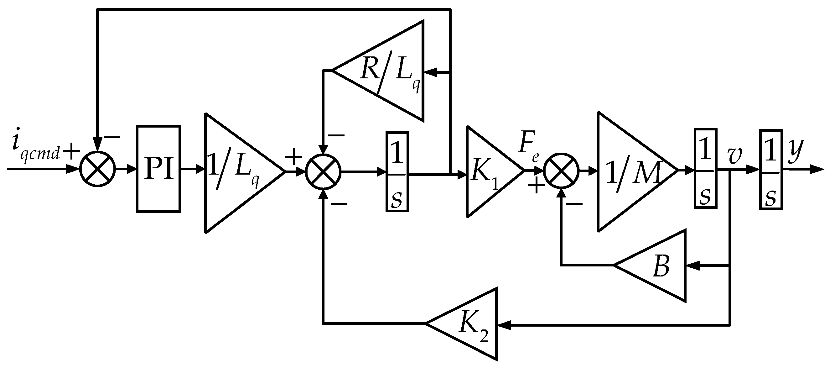
2.1. Mechanistic Model

In this paper, the motion platform’s performance characteristics, including ultra-high speed, frequent start–stop operations, and microscale precision positioning, are realized through the Y-axis, which is driven by a coreless permanent magnet synchronous linear motor. The control system of the Y-axis typically consists of a current loop, speed loop, and position loop, as shown in Figure 1, with the current loop PI controller being implemented internally within the driver. Consequently, for the model identification of the Y-axis of the motion platform, both the current loop of the driver and the linear motor are treated as a unified system.
Before performing model identification, it is essential to determine the model order information of the unified system. Based on the current loop PI controller, the working principle of the linear motor and the motion equation, the block diagram of the q-axis current command to linear motor displacement is illustrated in Figure 2, where K 1 = 3 π P n Ψ P M 2 τ , K 2 = π Ψ P M τ L q , P n is the number of poles, Ψ P M is the magnetic flux of the linear motor, τ is the pole pitch of the linear motor, L q is the motor inductance, R is the motor resistance, M is the motor rotor mass, and B is the viscous friction coefficient.
The transfer function from the given current command to the motor displacement is
Y s I q c m d s = 3 π τ P n Ψ P M K p s + K i s 2 τ 2 M s + B L q s 2 + R + K p s + K i + 3 π 2 P n Ψ P M 2 s
where K p represents the proportional coefficient of current loop PI controller, and K i represents the integral coefficient of current loop PI controller.
Equation (1) is written as a parameterized transfer function, and the following equation is obtained.
Y s I q c m d s = b 1 s + b 0 s s 3 + a 2 s 2 + a 1 s + a 0
Therefore, it can be deduced that, theoretically, the transfer function model of the motion platform possesses four poles and one zero. Since the electrical time constant is typically much smaller than the mechanical one, the delay due to electrical transient response may be ignored, giving the following simplified model:
Y s I q c m d s = d 1 s + d 0 s s 2 + c 1 s + c 0
It can be seen from Equation (3) that the simplified model exhibits three poles, one zero, and is classified as a Type 1 system.

2.2. Model Identification

As illustrated in Figure 3, the tested motion platform is frequency swept to obtain the frequency domain characteristic data of the Y axis of the motion platform. A sinusoidal current signal is used as the excitation for the frequency sweep, with the sweep frequency set from 1 Hz to 1000 Hz to encompass the mechanical resonance range. Simultaneously, the sine output displacement is recorded. After processing the input signal and output signals, the actual frequency domain response curve of the Y axis of the motion platform is obtained, depicted by the black line in Figure 3.
Subsequently, the frequency domain characteristics are identified utilizing a Simulated Annealing Improved PSO (SA-IPSO) algorithm, and the identified transfer function model is
G p s = 73.03 s + 140280 s s 2 + 66.79 s + 436.69
It can be seen from Figure 4 that the identified transfer function demonstrates strong congruence with experimental measurements within approximately 1000 rad/s, exhibiting closely aligned dynamic characteristics and minimal deviation over a range of approximately 1000 rad/s. This quantitative validation confirms the model’s fidelity in capturing the system’s essential dynamics, thereby establishing it as a rigorous mathematical foundation for the development of nominal model-based composite control strategies.

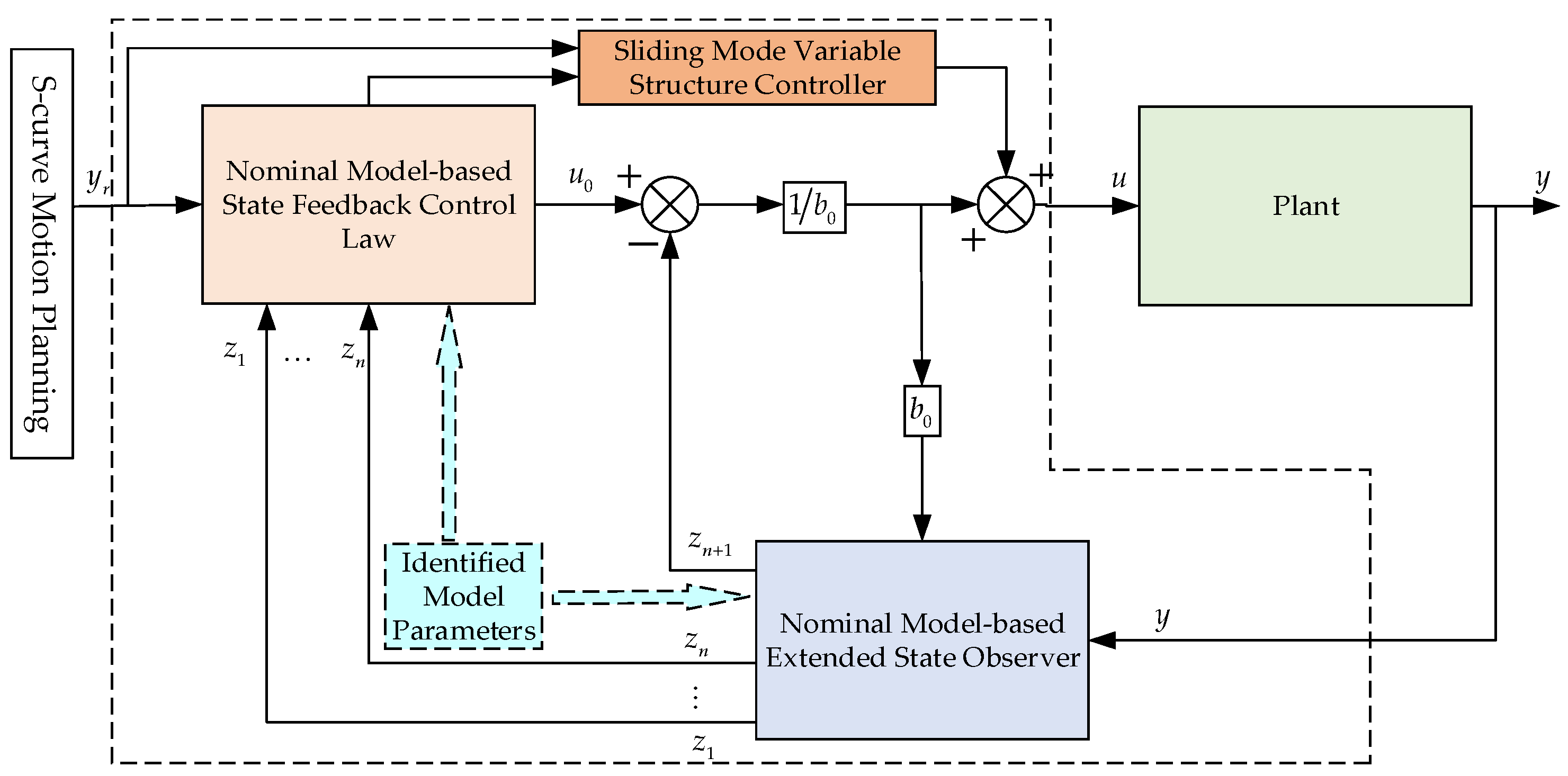
3. The Proposed Composite Control Strategy

A novel composite control scheme is developed through the synergistic integration of a nominal model-based LADRC (NMLADRC) and SMC. The architectural framework of this composite control scheme is systematically presented in Figure 5.
As illustrated in Figure 5, the proposed composite control structure demonstrates threefold technical merits: Firstly, the intrinsic robustness of SMC against parametric uncertainties and external disturbances effectively compensates for LADRC’s observer-induced phase lag. Secondly, the complementary dynamic characteristics between the two control strategies substantially enhance the motion control platform’s transient response. Thirdly, the SMC component synergistically interacts with the disturbance rejection capabilities of model identification-enhanced LADRC, forming a dual-compensation mechanism that improves positioning accuracy. This coordinated control paradigm not only preserves the disturbance rejection advantages of LADRC but also inherits the finite-time convergence property of SMC, ultimately optimizing the system’s dynamic stiffness and tracking precision in high-speed precision motion control scenarios.

3.1. NMLADRC

The unknown total disturbance of the system is defined as shown in Equation (5), and it is assumed to be bounded and differentiable.
f = a 0 a 0 n y a 1 a 1 n y ˙ a 2 a 2 n y ¨ + b 1 u ˙ + b b 0 u
where a 0 n = 0 , a 1 n = 436.69 , a 2 n = 66.79 , and b 0 = 140280 are the nominal model parameters of a 0 , a 1 , a 2 , and b , respectively.
Subsequently, Equation (4) can be rewritten as
y = a 1 n y ˙ a 2 n y ¨ + f + b 0 u
Defining x 1 = y , x 2 = y ˙ , and x 3 = y ¨ , x 4 = f , the state equation of Equation (6) can be expressed as
z ˙ 1 = z 2 β 1 z 1 y z ˙ 2 = z 3 β 2 z 1 y z ˙ 3 = a 1 n z 2 a 2 n z 3 + z 4 β 4 z 1 y + b 0 u z ˙ 4 = β 4 z 1 y
According to Equation (7), the nominal model-based ESO (NMESO) is
z ˙ 1 = z 2 β 1 z 1 y z ˙ 2 = z 3 β 2 z 1 y z ˙ 3 = a 1 n z 2 a 2 n z 3 + z 4 β 4 z 1 y + b 0 u z ˙ 4 = β 4 z 1 y
where z 1 , z 2 , z 3 , and z 4 are the estimates of x 1 , x 2 , x 3 , and x 4 , respectively; β 1 , β 2 , β 3 , and β 4 are the gains of NMESO.
The control law of NMLADRC is
u N M L A D R C = u 0 z 4 b 0
where u 0 is implemented using
u 0 = k p y r z 1 k d 1 z 2 k d 2 z 3
where y r is the reference signal, k p is the proportional coefficient, and k d 1 and k d 2 are the differential coefficients.
The bandwidth parameterization method is used to tune the control parameter of NMLADRC, and the resulting expressions are:
β 1 = 4 w o a 2 n β 2 = 6 w o 2 β 1 a 2 n a 1 n β 3 = 4 w o 3 β 2 a 2 n β 1 a 1 n a 0 n β 4 = w o 4 k p = w c 3 k d 1 = 3 w c 2 a 1 n k d 2 = 3 w c a 2 n
where ω c denotes the controller bandwidth, and ω o represents the observer bandwidth, which should be 3–10 times larger than ω c .

3.2. SMC

The tracking error and its derivative are defined as
e = y r y e ˙ = y ˙ r y ˙ e ¨ = y ¨ r y ¨ e = y r y
Substituting u = u N M L A D R C + u S M C into Equation (7), Equation (13) is obtained.
y = a 1 n y ˙ a 2 n y ¨ + e ˜ 4 + u 0 + b 0 u S M C
where e ˜ 4 = x 4 z 4 is the disturbance estimation error of NMESO.
Considering Equation (10), and z 1 x 1 = y , z 2 x 2 = y ˙ , and z 3 x 3 = y , u 0 are simplified to
u 0 k p y r y k d 1 y ˙ k d 2 y ¨ = k p e k d 1 y ˙ r e ˙ k d 1 y ¨ r e ¨
If the reference signal changes slowly (i.e., y ˙ r 0 , y ¨ r 0 ), it can be further approximated as
u 0 k p e + k d 1 e ˙ + k d 2 e ¨
Substituting Equation (15) into Equation (13), and combining the definition of tracking error in Equation (12), we can obtain the error dynamic equation of the system:
e = y r a 1 n y ˙ a 2 n y ¨ + e ˜ 4 + k p e + k d 1 e ˙ + k d 2 e ¨ + b 0 u S M C = y r + a 1 n y ˙ + a 2 n y ¨ e ˜ 4 k p e k d 1 e ˙ k d 2 e ¨ b 0 u S M C
The corresponding sliding mode surface is designed as
s = c 1 e + c 2 e ˙ + e ¨
where c 1 and c 2 are the design parameters of the sliding mode surface. They are related to the system’s dynamic performance, where increasing c 1 can enhance the control speed of the system, while c 2 alters the system’s damping.
To address the chattering phenomenon induced by SMC, an exponential reaching law is used, which is expressed as follows:
s ˙ = k 1 sgn s k 2 s
where k 1 and k 2 represent the control parameters of the control law. A larger value of k 1 improves the elimination of chattering, while increasing k 2 speeds up the approach to the sliding surface, thereby reducing the impact of phase lag and achieving better tracking.
The derivative of the sliding mode surface is as follows:
s ˙ = c 1 e ˙ + c 2 e ¨ + e = c 1 e ˙ + c 2 e ¨ + y r + a 1 n y ˙ + a 2 n y ¨ e ˜ 4 k p e k d 1 e ˙ k d 2 e ¨ b 0 u S M C
Let the derivative of the sliding model surface equal to the exponential reaching law, and the sliding mode control law can be obtained as
u S M C = 1 b 0 c 1 e ˙ + c 2 e ¨ + y r + a 1 n y ˙ + a 2 n y ¨ e ˜ 4 k p e k d 1 e ˙ k d 2 e ¨ + k 1 sgn s + k 2 s = 1 b 0 y r + k 2 c 1 k p e + c 1 k d 1 + k 2 c 2 e ˙ + c 2 k d 2 + k 2 e ¨ e ˜ 4 + k 1 sgn s
In contrast to conventional SMC architectures, the SMC formulation embedded within the composite control strategy synthesizes both intrinsic control parameters and interdependent parameters from the NMLADRC framework, establishing a co-designed parametric coupling mechanism.

3.3. Stability Analysis

3.3.1. NMESO Stability

Defining the observation error e ˜ 1 = x 1 z 1 , e ˜ 2 = x 2 z 2 , e ˜ 3 = x 3 z 3 , e ˜ 4 = x 4 z 4 , the error state of NMESO is expressed as e ˜ = e ˜ 1 e ˜ 2 e ˜ 3 e ˜ 4 T . Combining Equations (7) and (8), the state–space equation is obtained as
e ˜ ˙ = A e ˜ e ˜ + B e ˜ h
where A e ˜ satisfies its characteristic polynomial s + w 0 4 , and its eigenvalues are all located at s = w o , ensuring A e ˜ is the Hurwitz matrix and h is the disturbance change rate.
The Lyapunov function on NMESO is selected as
V o b s = e ˜ T P e ˜
where P satisfies A e ˜ T P + P A e ˜ = Q P , Q > 0 .
Subsequently, the time derivative of the Lyapunov function V o b s is analytically derived as
V ˙ o b s = e ˜ T A e ˜ T P + P A e ˜ e ˜ + 2 e ˜ T P B e ˜ h - λ min Q e ˜ 2 + 2 P B e ˜ H e ˜
Furthermore, applying Young’s inequality ( 2 a b ε a 2 + b 2 ε ) and taking ε = λ min Q 2 , Equation (23) can be expressed as
V ˙ o b s λ min Q 2 e ˜ 2 + 2 P B e ˜ 2 H 2 λ min Q
When e ˜ 4 P B e ˜ 2 H 2 λ min Q 2 , Equation (24) can be expressed as
V ˙ o b s λ min Q 4 e ˜ 2
According to Uniformly Ultimately Boundedness (UUB), the observation error e ˜ exponentially converges to the domain.

3.3.2. SMC Stability

The Lyapunov function on MSC is selected as
V S M C = 1 2 s 2
The time derivative of the Lyapunov function V S M C is derived as
V ˙ S M C = s s ˙ = s k 1 sgn s k 2 s k 2 s 2 k 1 s
It shows that the sliding mode surface s = 0 is reachable in a finite time, and the tracking error exponentially converges to zero.

3.3.3. Overall Stability of Composite Control System

The Lyapunov function of the composite control system is constructed as
V = V o b s + γ V S M C γ > 0
The time derivative of the Lyapunov function V is derived as
V ˙ λ min Q 2 e ˜ 2 + 2 P B e ˜ 2 H 2 λ min Q γ k 2 s 2 γ k 1 s
When e ˜ and s are large enough, the negative terms dominate, and the system state enters and remains in the set:
e ˜ , s | λ min Q 2 e ˜ 2 + γ k 2 s 2 + γ k 1 s 2 P B e ˜ 2 H 2 λ min Q
That is, the tracking error and the observation error satisfy UUB.

4. Simulation Results and Analysis

To validate the effectiveness of the composite control architecture proposed in this paper, which is marked as NMLADRC-SMC, some simulation cases are conducted on the control system of the die bonding machine’s motion platform built on MATLAB/Simulink. Moreover, to further verify the advantages of the proposed composite control architecture, the results simulated by the proposed composite control architecture are compared with PI controller, LADRC, and NMLADRC.
The parameter tuning process for the NMLADRC-SMC involves two interconnected stages. Firstly, following the control law of NMLADRC, as shown in Equation (10), the bandwidth parameterization method is utilized to derive the tuning expressions outlined in Equation (11). This adjustment of two critical parameters: the control bandwidth w c and the ESO bandwidth w o . To ensure prioritized disturbance estimation over control execution, the bandwidth separation principle (e.g., setting w o to 3–10 times w c ) is rigorously applied. The selection of these two bandwidths necessitates a comprehensive consideration of multiple performance metrics, including system settling time, positioning time, overshoot, and robustness.
Subsequently, for the sliding mode control law, as shown in Equation (20), the design focuses on determining the sliding surface coefficients to regulate error convergence rates. A critical trade-off exists between chattering attenuation and robust tracking performance, demanding careful coordination with the NMLADRC parameters.
The parameters are iteratively optimized through a systematic framework combining theoretical analysis (e.g., stability verification via Lyapunov methods), and high-fidelity simulations under varied operational scenarios. This integrated approach ensures the final parameter set achieves stable operation, rapid dynamic response, and effective disturbance attenuation, while mitigating conflicts between observer-based estimation and sliding mode enforcement.

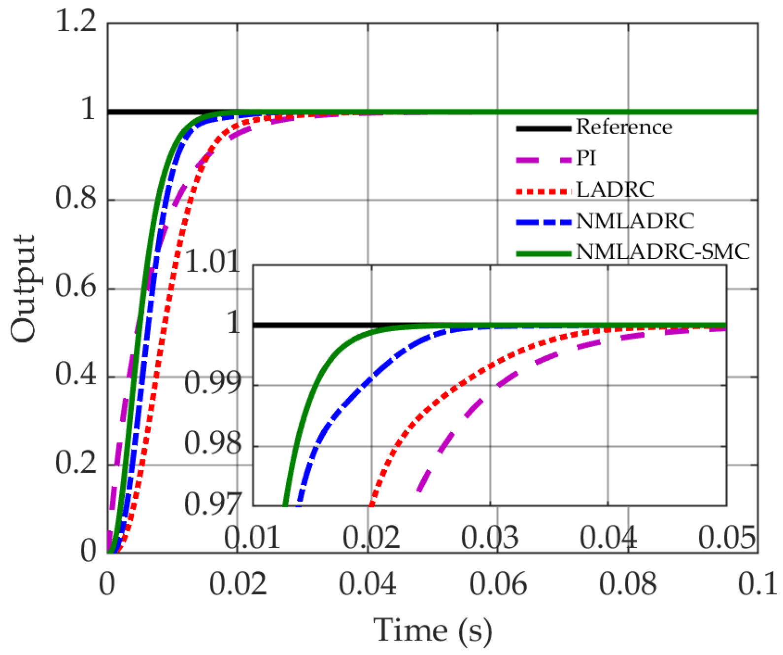
4.1. Dynamic and Static Characteristic Analysis

Firstly, a unit step reference signal is applied to the four different control system of the die bonding machine’s motion platform. The system’s dynamic response characteristics are subsequently evaluated through the displacement tracking response curve, as quantitively illustrated in Figure 6.
As evidenced by the comparative results presented in Figure 6, the displacement transient response profiles exhibit no overshoot characteristics with comparable rise time performance observed across all schemes. However, notable discrepancies emerge in the settling times (within ±2% error band): PI (0.02609 s), LADRC (0.02214 s), NMLADRC (0.01537 s), and NMLADRC-SMC (0.01367 s). Quantitative analysis reveals that the proposed NMLADRC-SMC architecture achieves 47.60%, 38.26%, and 11.06% reduction in settling time compared to PI, LADRC, and NMLADRC, respectively.
To further validate the tracking performance of the composite controller, a 1 Hz unit-amplitude sinusoidal reference signal is implemented in four distinct control systems of the die bonding machine’s motion platform. The resultant sinusoidal displacement tracking profiles and their corresponding error trajectories are comparatively presented in Figure 7.
As depicted in Figure 7a, under equivalent amplitude conditions with zero overshoot, the composite controller demonstrates the smallest phase among the evaluated control strategies and exhibits the smallest phase lag. Figure 7b reveals that all four control algorithms exhibit periodic fluctuations with consistent amplitude characteristics in their error profiles. Specifically, the conventional PI controller manifests the maximum tracking error amplitude, whereas the proposed NMLADRC-SMC algorithm achieves superior tracking accuracy with minimum error magnitude. For systematic evaluation of the four control strategies regarding tracking accuracy and phase synchronization characteristics, quantitative comparisons are presented in Table 2.
As evidenced by the comparative data in Table 2, the proposed NMLADRC-SMC demonstrates superior performance metrics in both phase lag and maximum tracking error minimization when benchmarked against PI, LADRC and NMLADRC strategies, achieving phase lag reductions of 50.04%, 36.34% and 23.07%, respectively.

4.2. Robustness Evaluation Under Disturbances and Parametric Uncertainties

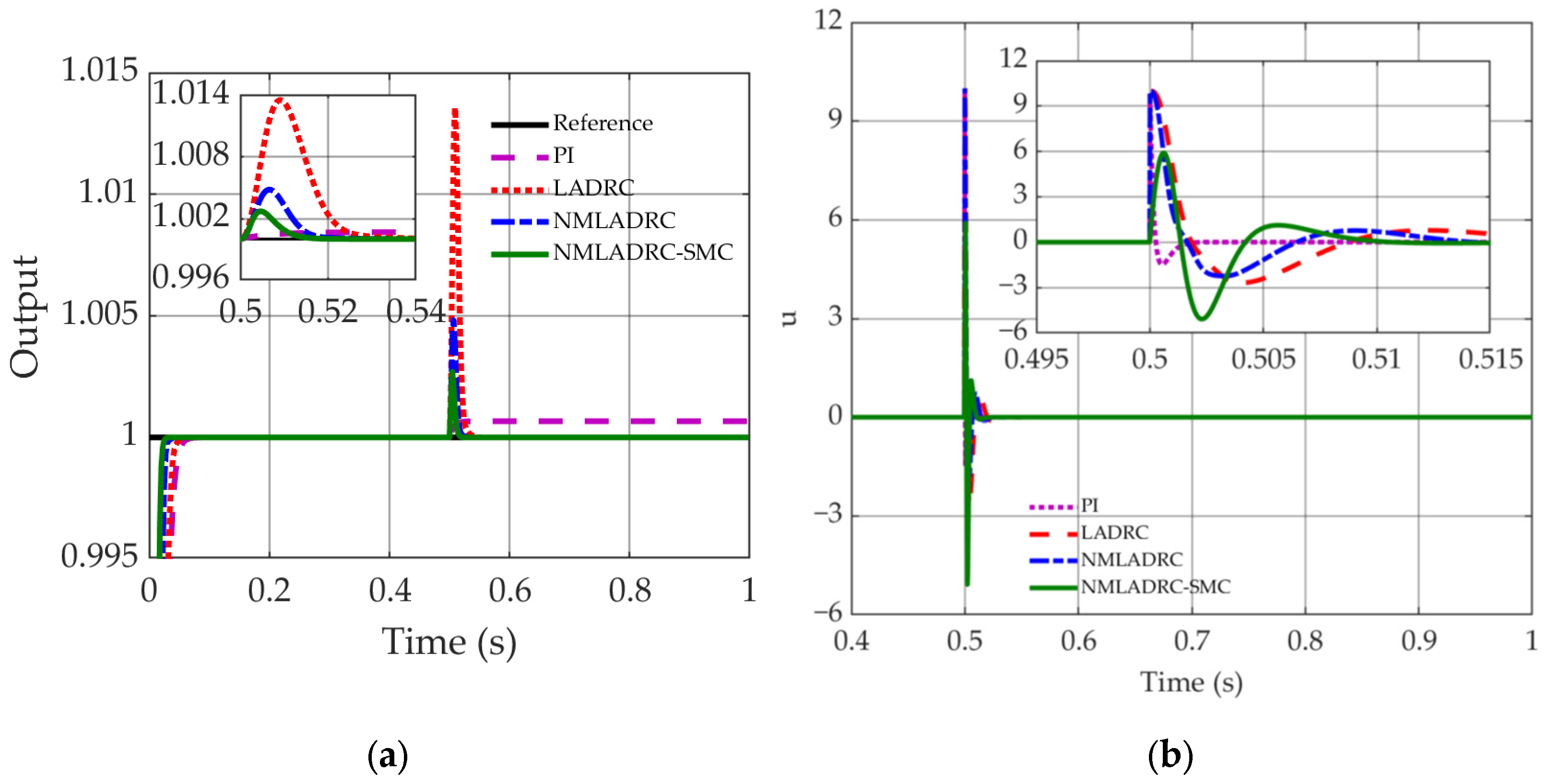
4.2.1. External Step Disturbance

To assess the disturbance rejection robustness of the four distinct control strategies, step disturbance signals with amplitudes of 10, 50, 100 are injected into the control system of the die bonding machine’s motion platform at 0.5 s during the simulation, respectively. The output transient response characteristics and control effort variations under these disturbances are quantitatively evaluated through displacement tracking profiles and actuation signal trajectories, as presented in Figure 8, Figure 9 and Figure 10, respectively.
As evidenced by the comparative trajectory profiles in Figure 8, Figure 9 and Figure 10, under stepped disturbance input conditions, the PI controller demonstrates fundamental tracking failure with persistent offset, while the LADRC, NMLADRC and NMLADRC-SMC exhibit distinct transient deviations at disturbance onset. Quantitative analysis reveals that a maximum transient deviation of 13.58% (LADRC), 4.82% (NMLADRC) and 2.71% (NMLADRC-SMC) under 100 step disturbance, establishing a clear hierarchical relationship in disturbance sensitivity. Although all advanced controllers achieve disturbance suppression with settling times under 0.021 s, the proposed NMLADRC-SMC exhibits 66.04%, 40.92% faster error convergence compared to conventional LADRC and NMLADRC, respectively. This temporal precision advantage is quantitatively corroborated by the control input energy consumption, revealing that the proposed NMLADRC-SMC exhibits about 40.91% reduction in maximum control input amplitude compared to NMLADRC under identical disturbance conditions.

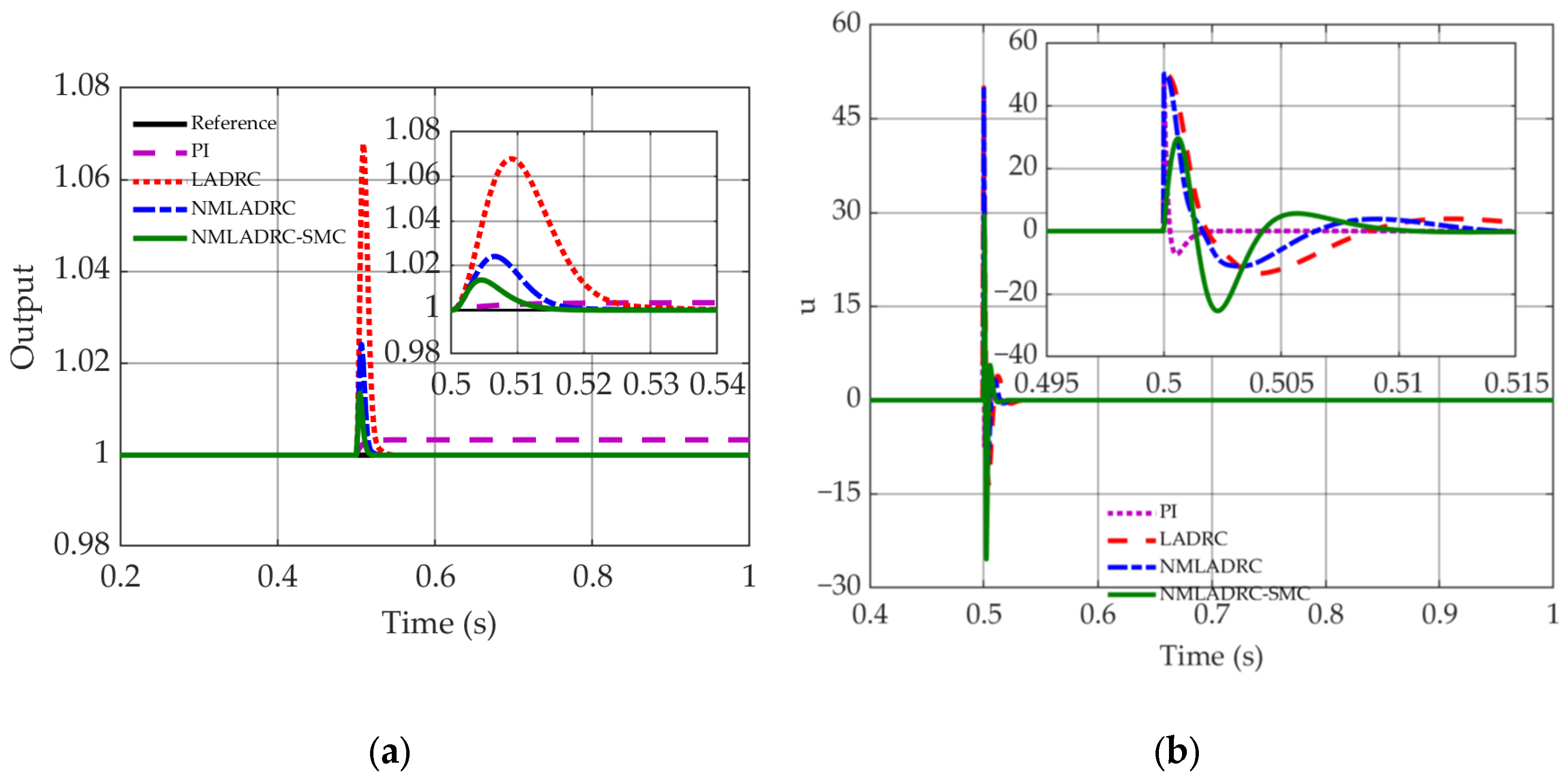
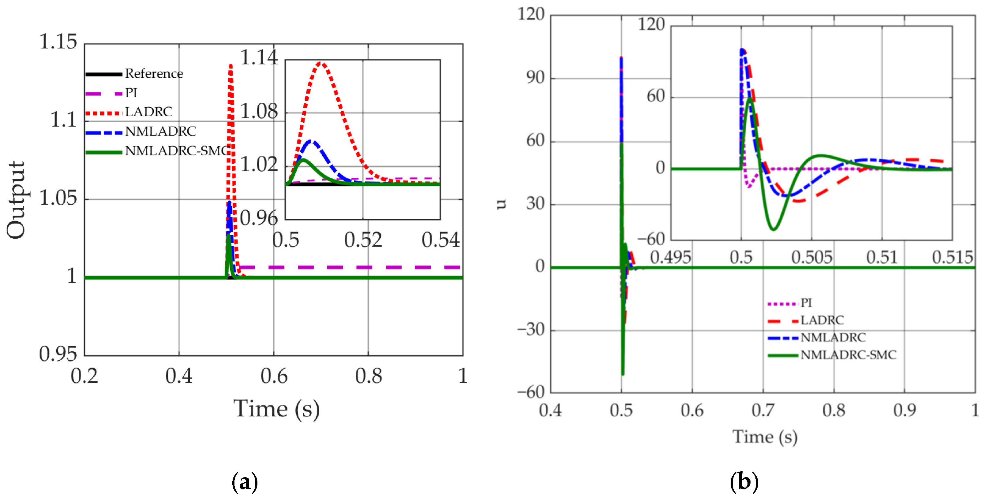
4.2.2. Model Parameter Uncertainties

To systematically evaluate the robustness of four distinct control strategies against parametric uncertainties, a simulation-based sensitivity analysis is conducted by introducing perturbations to the different parameters of the plant model. Given space limitations, this paper specifically focuses on the dynamic characteristics of the control system of the die bonding machine’s motion platform under ±50% variations in b0, because b0 is the pivotal design parameter in LADRC architecture. Figure 11 illustrates the closed-loop transient dynamics and actuation signal behavior under a 50% parametric reduction (b0→0.5b0), while Figure 12 presents the corresponding profiles under a 50% parametric augmentation (b0→1.5b0).
Figure 11 and Figure 12 reveal that parametric augmentation of b 0 exhibits negligible impact on the closed-loop transient dynamics, whereas a 50% reduction in b 0 significantly degrades settling performance and induces sustained oscillations. Concurrently, b 0 perturbations amplify the amplitude of actuation signal fluctuations in the control input.

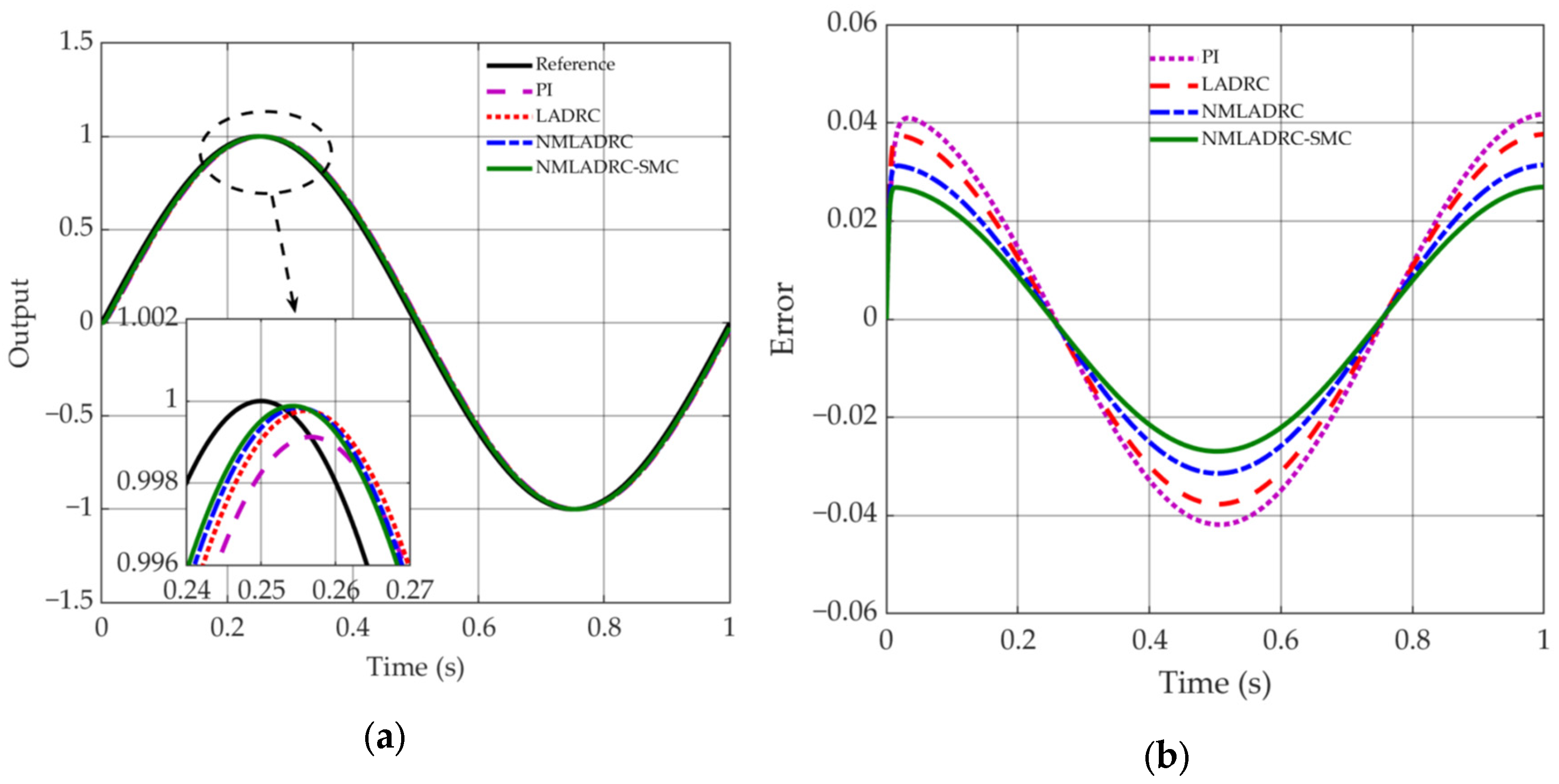
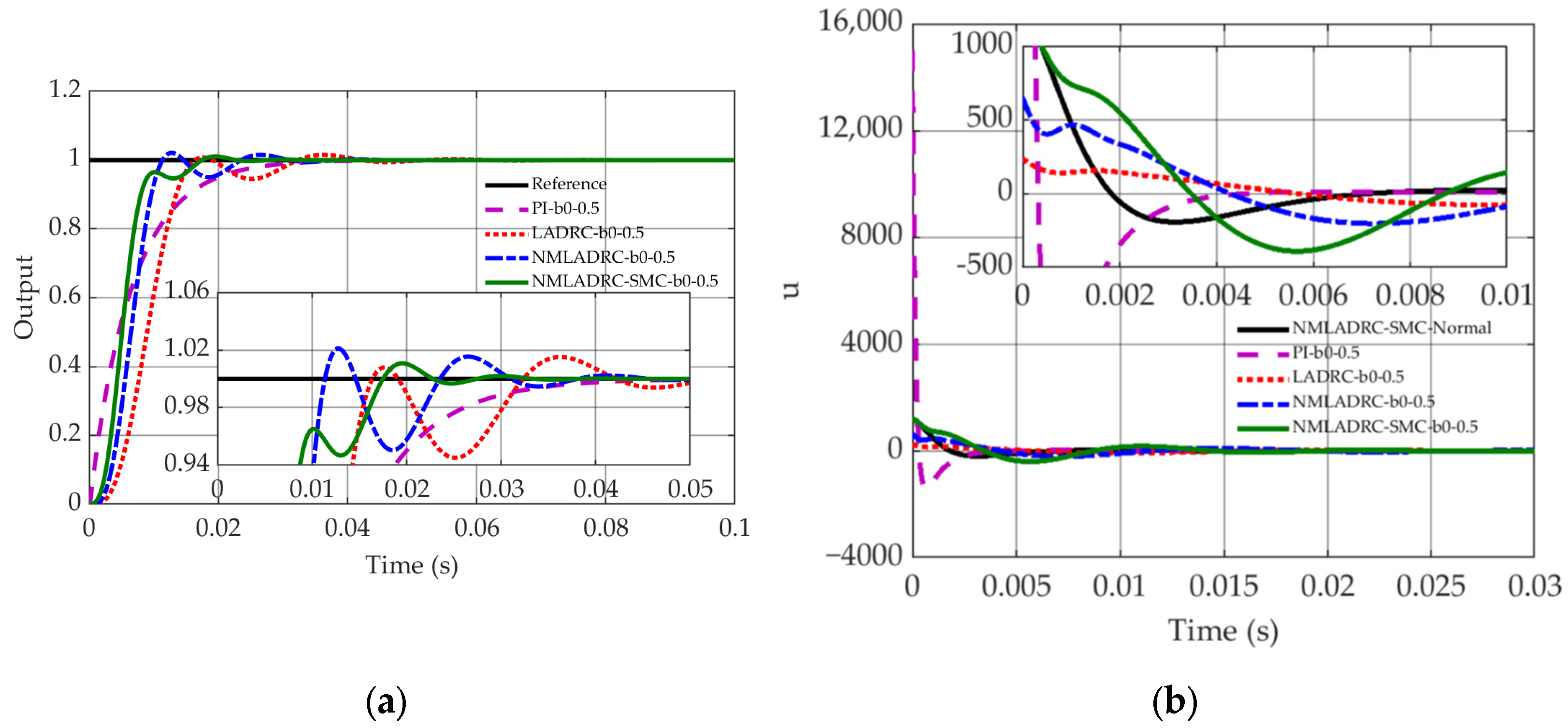
4.3. Servo Tracking Performance Analysis Under High-Acceleration and High-Speed Operating Conditions

Following comprehensive simulation validations, comparative studies on servo tracking performance are systematically conducted under high-acceleration and high-speed operational regimes. The S-curve reference trajectory is replicated from the actual motion trajectory planning of the test platform depicted in Figure 3, with kinematic boundaries constrained to a maximum jerk of 21 × 103 m/s3, peak acceleration of 160 m/s2, and maximum velocity of 2.8 m/s. This trajectory is implemented across three control architectures governing the Y axis of the die bonding machine’s motion platform, with captured transient dynamics quantitatively depicted in Figure 13 through displacement tracking trajectories, where the test profile is derived from the actual test results of the motion platform, and its control system adopts a composite control architecture consisting of feedforward control and feedback PI control with notch filters. Subsequently, the Y-axis positioning time at target positioning accuracies of 10 μm, 5 μm, 3 μm and 2 μm is quantitatively assessed for each control strategy, with comparative data systematically tabulated in Table 3.
As quantitatively demonstrated by Figure 13 and Table 3, the proposed NMLADRC-SMC control algorithm exhibits superior transient response metrics, achieving positioning time of 6.56 ms, 7.65 ms, 8.43 ms, and 9.05 ms at positioning accuracies of ±10 μm, ±5 μm, ±3 μm, and ±2 μm, respectively. Comparative analysis reveals statistically significant performance enhancements: At the 5 μm accuracy threshold, the proposed control architecture reduces positioning time by 31.51%, 56.31%, and 44% compared to the NMLADRC, LADRC and the actual test. Furthermore, when benchmarked against the actual experimental data, the proposed NMLADRC-SMC achieves progressive time reductions of 13.23% (10 μm), 44% (5 μm), 41.01% (3 μm), and 89.92% (2 μm), demonstrating precise positioning capabilities.
To sum up the above, the simulation results conclusively validate the proposed composite control architecture’s superior disturbance rejection robustness and transient response performance. The enhanced performance originates from the composite architecture’s dual capability: the ESO achieves precision estimation of disturbances, while the SMC guarantees finite-time convergence via an exponential reaching law. Their synergistic interaction ensures the concurrent realization of robust tracking accuracy and rapid transient convergence.

5. Conclusions

A novel composite control architecture, termed NMLADRC-SMC, that synergistically integrates NMLADRC with SMC is proposed to address the critical challenges of high-precision positioning in die bonding machines. Through systematic simulation, the proposed NMLADRC-SMC demonstrates significant advantages over PI, LADRC, NMLADRC, yielding 13–89.92% shorter positioning times at ±2–±10 μm positioning accuracy thresholds.
However, this study presents two primary limitations: Firstly, the current parameter tuning of the composite controller relies on empirical adjustments derived from the linear model of the motion platform, while neglecting its inherent high-frequency dynamics exceeding 200 Hz, as demonstrated in Figure 4. Secondly, it lacks noise sensitivity analysis and robustness assessment against measurement uncertainties. To transcend these limitations while addressing emerging challenges in ultra-precision motion control, three actionable future directions are proposed for subsequent investigation: (1) development of adaptive parameter tuning mechanisms for ADRC to maintain consistent servo performance under varying operational conditions; (2) co-design methodology for ADRC that optimizes the trade-off between noise sensitivity suppression and disturbance rejection robustness, particularly targeting high-frequency mechanical resonances induced by linear motor transients during high-acceleration maneuvers; and (3) formulation of saturation-aware ADRC architectures incorporating nonlinear constraint handling to ensure bounded disturbance compensation that respects actuator physical limitations and prevents control saturation failures. The systematic resolution of these challenges would enable significant performance enhancements: extended control bandwidth, effective mitigation of positioning jitter phenomena, and improved operational reliability for semiconductor manufacturing equipment. Through systematic investigation of these critical aspects, ADRC-based control systems could transcend current implementation barriers, establishing new benchmarks in precision motion control applications.

Author Contributions

Conceptualization, Y.Z. and W.L. (Wen Li); methodology, H.C. and X.Z.; validation, H.C., X.Z. and W.L. (Weiming Liang); test, X.Z., W.L. (Weiming Liang) and H.C.; writing—original draft preparation, H.C., X.Z. and W.L. (Weiming Liang); writing—review and editing, Y.Z., W.L. (Wen Li) and H.C. All authors have read and agreed to the published version of the manuscript.

Funding

This research received no external funding.

Data Availability Statement

All data used to support the findings of this study are available from the corresponding author upon request.

Conflicts of Interest

Author Wen Li was employed by the company Wuxi Autowell Technology Co., Ltd. The remaining authors declare that the research was conducted in the absence of any commercial or financial relationships that could be construed as a potential conflict of interest.

References

  1. Guste, R.R.A.; Mariñas, K.A.A.; Ong, A.K.S. Efficiency Analysis of Die Attach Machines Using Overall Equipment Effectiveness Metrics and Failure Mode and Effects Analysis with an Ishikawa Diagram. Machines 2024, 12, 467. [Google Scholar] [CrossRef]
  2. Braembussche, P.; Swevers, J.; Brussel, H. Design and Experimental Validation of Robust Controllers for Machine Tool Drives with Linear Motor. Mechatronics 2001, 11, 545–562. [Google Scholar] [CrossRef]
  3. Liu, T.-H.; Lee, Y.-C.; Chang, Y.-H. Adaptive Controller Design for a Linear Motor Control System. IEEE Trans. Aerosp. Electron. Syst. 2004, 40, 601–615. [Google Scholar]
  4. Tan, K.; Huang, S.; Dou, H.; Lee, T.; Chin, S.; Lim, S. Adaptive Robust Motion Control for Precise Trajectory Tracking Application. ISA Trans. 2001, 40, 57–71. [Google Scholar] [CrossRef]
  5. Xu, L.; Yao, B. Adaptive Robust Precision Motion Control of Linear Motors with Negligible Electrical Dynamics: Theory and Experiments. IEEE/ASME Trans. Mechatron. 2001, 6, 444–452. [Google Scholar]
  6. Li, Y.; Wikander, J. Model Reference Discrete-Time Sliding Mode Control of Linear Motor Precision Servo Systems. Int. J. Mechatron. 2004, 14, 835–851. [Google Scholar] [CrossRef]
  7. Han, J. From PID to Active Disturbance Rejection Control. IEEE Trans. Ind. Electron. 2009, 56, 900–906. [Google Scholar] [CrossRef]
  8. Gao, Z. Scaling and bandwidth-parameterization based controller tuning. In Proceedings of the 2003 American Control Conference, Denver, CO, USA, 4–6 June 2003; pp. 4989–4996. [Google Scholar]
  9. Huang, J.; Ma, P.; Gao, F.; Shi, X. Research on Position Servo System Based on Fractional-Order Extended State Observer. IEEE Access 2020, 8, 102748–102756. [Google Scholar] [CrossRef]
  10. Liu, L.; Liu, Y.; Zhou, L.; Wang, B.; Cheng, Z.; Fan, H. Cascade ADRC with Neural Network-based ESO for Hypersonic Vehicle. J. Frankl. Inst. 2023, 360, 9115–9158. [Google Scholar] [CrossRef]
  11. Michalski, J.; Mrotek, M.; Pazderski, D.; Kozierski, P.; Retinger, M. Improving Performance of ADRC Control Systems Affected by Measurement Noise Using Kalman Filter-Tuned Extended State Observer. Electronics 2024, 13, 4916. [Google Scholar] [CrossRef]
  12. Yang, F.; Su, X.; Ren, X. Optimization of Active Disturbance Rejection Control System for Vehicle Servo Platform Based on Artificial Intelligence Algorithm. Electronics 2025, 14, 752. [Google Scholar] [CrossRef]
  13. Xu, H.; Zhang, J.; Liu, J.; Cao, Y.; Ma, A. Optimization of Ship Permanent Magnet Synchronous Motor ADRC Based on Improved QPSO. Appl. Sci. 2025, 15, 1608. [Google Scholar] [CrossRef]
  14. Zhou, Z.; Wang, L.; Wang, Y.; Zhou, X.; Tong, Y. Research on Active Disturbance Rejection Control with Parameter Tuning for Permanent Magnet Synchronous Motor Based on Improved PSO Algorithm. Electronics 2024, 13, 3436. [Google Scholar] [CrossRef]
  15. Gao, B.; Shen, W.; Dai, Y.; Ye, Y. Parameter tuning of auto disturbance rejection controller based on improved glowworm swarm optimization algorithm. Assem. Autom. 2022, 42, 427–444. [Google Scholar] [CrossRef]
  16. Zhao, C.; Zuo, Y.; Wang, H.; Hou, Q.; Lee, C.H.T. Smooth speed control of permanent magnet synchronous machine using back propagation neural network. World Electr. Veh. J. 2023, 14, 92. [Google Scholar] [CrossRef]
  17. Ding, H.; Liu, S.; Wang, Z.; Zhang, H.; Wang, C. An ADRC parameters self-tuning controller based on RBF neural network for multi-color register system. Machines 2023, 11, 320. [Google Scholar] [CrossRef]
  18. Wang, Y.; Fang, S.; Hu, J.; Huang, D. A novel active disturbance rejection control of PMSM based on deep reinforcement learning for more electric aircraft. IEEE Trans. Energy Convers. 2023, 38, 1461–1470. [Google Scholar] [CrossRef]
  19. Qin, H.; Tan, P.; Chen, Z.; Sun, M.; Sun, Q. Deep reinforcement learning based active disturbance rejection control for ship course control. Neurocomputing 2022, 484, 99–108. [Google Scholar] [CrossRef]
  20. Guo, B.; Bacha, S.; Alamir, M. A review on ADRC based PMSM control designs. In Proceedings of the IECON 2017—43rd Annual Conference of the IEEE Industrial Electronics Society, Beijing, China, 29 October–1 November 2017; pp. 1747–1753. [Google Scholar]
  21. Fareh, R.; Khadraoui, S.; Abdallah, M.Y.; Baziyad, M.; Bettayeb, M. Active disturbance rejection control for robotic systems: A review. Mechatronics 2021, 80, 102671. [Google Scholar]
  22. Khadraoui, S.; Fareh, R.; Baziyad, M.; Elbeltagy, M.B.; Bettayeb, M. A Comprehensive Review and Applications of Active Disturbance Rejection Control for Unmanned Aerial Vehicles. IEEE Access 2024, 12, 185851–185868. [Google Scholar] [CrossRef]
  23. Tu, Y.; Wang, R.; Su, W. Active Disturbance Rejection Control—New Trends in Agricultural Cybernetics in the Future: A Comprehensive Review. Machines 2025, 13, 111. [Google Scholar] [CrossRef]
  24. Li, J.; Zhang, L.; Li, S.; Mao, Q.; Mao, Y. Active Disturbance Rejection Control for Piezoelectric Smart Structures: A Review. Machines 2023, 11, 174. [Google Scholar] [CrossRef]
  25. Gao, Z.; Hu, S.; Jiang, F. A Novel Motion Control Design Approach Based on Active Disturbance Rejection. In Proceedings of the 40th IEEE Conference on Decision and Control (Cat. No. 01Ch37228), Orlando, FL, USA, 4–7 December 2001; IEEE: Piscataway, NJ, USA, 2001; Volume 5, pp. 4877–4882. [Google Scholar]
  26. Xue, W.; Madonski, R.; Lakomy, K.; Gao, Z.; Huang, Y. Add-on Module of Active Disturbance Rejection for Set-Point Tracking of Motion Control Systems. IEEE Trans. Ind. Appl. 2017, 53, 4028–4040. [Google Scholar] [CrossRef]
  27. Garrido, R.; Luna, L. Robust ultra-precision motion control of linear ultrasonic motors: A combined ADRC-Luenberger observer approach. Control. Eng. Pract. 2021, 111, 104812. [Google Scholar] [CrossRef]
  28. Su, Y.X.; Zheng, C.H.; Duan, B.Y. Automatic Disturbances Rejection Controller for Precise Motion Control of Permanent-Magnet Synchronous Motors. IEEE Trans. Ind. Electron. 2005, 52, 814–823. [Google Scholar] [CrossRef]
  29. Sun, K.; Zhao, Y. A New Robust Algorithm to Improve the Dynamic Performance on the Position Control of Magnet Synchronous Motor Drive. In Proceedings of the 2010 2nd International Conference on Future Computer and Communication, Wuhan, China, 21–24 May 2010; pp. V3-268–V3-272. [Google Scholar]
  30. Zuo, Y.; Liu, C.; Hui, F.; Zhang, T.; Hu, Y. A Decoupled Active Disturbance Rejection Controller for PMSM Speed-Regulation System with Position Feedback. In Proceedings of the 2015 18th International Conference on Electrical Machines and Systems (ICEMS), Pattaya, Thailand, 25–28 October 2015; pp. 1769–1774. [Google Scholar]
  31. Gai, J.; Huang, S.; Huang, Q.; Li, M.; Wang, H.; Luo, D. A New Fuzzy Active-Disturbance Rejection Controller Applied in PMSM Position Servo System. In Proceedings of the 2014 17th International Conference on Electrical Machines and Systems (ICEMS), Hangzhou, China, 22–25 October 2014; pp. 2055–2059. [Google Scholar]
  32. Gao, J.; Kuang, J.; Huang, S.; Huang, S.; Xu, Z.; Chen, Y. A Novel Position Controller for PMSM Servo System Based on Variable Structure Active Disturbance Rejection Controller. In Proceedings of the 2011 International Conference on Electrical Machines and Systems, Beijing, China, 20–23 August 2011; pp. 1–5. [Google Scholar]
  33. Sira-Ramírez, H.; Linares-Flores, J.; García-Rodríguez, C.; Contreras-Ordaz, M.A. On the Control of the Permanent Magnet Synchronous Motor: An Active Disturbance Rejection Control Approach. IEEE Trans. Control. Syst. Technol. 2014, 22, 2056–2063. [Google Scholar] [CrossRef]
  34. Zurita-Bustamante, E.W.; Sira-Ramirez, H.; Linares-Flores, J. On the Sensorless Rotor Position Control of the Permanent Magnet Synchronous Motor: An Active Disturbance Rejection Approach. In Proceedings of the 2016 13th International Conference on Power Electronics (CIEP), Guanajuato, Mexico, 20–23 June 2016; pp. 12–17. [Google Scholar]
  35. Fu, C.; Tan, W. Tuning of linear ADRC with known plant information. ISA Trans. 2016, 65, 384–393. [Google Scholar] [CrossRef]
Figure 1. Three-loop control structure of the Y-axis of the motion platform.
Symmetry 17 00636 g001
Figure 2. Block diagram of q-axis current command to linear motor displacement.
Symmetry 17 00636 g002
Figure 3. The tested motion platform.
Symmetry 17 00636 g003
Figure 4. Comparison between identified curve and frequency sweep curve.
Symmetry 17 00636 g004
Figure 5. Architectural framework of the composite control scheme.
Symmetry 17 00636 g005
Figure 6. Step Response of the System.
Symmetry 17 00636 g006
Figure 7. Sine signal system response. (a) Sine displacement tracking curve; (b) Sine displacement tracking error curve.
Symmetry 17 00636 g007
Figure 8. Dynamic response with a step disturbance amplitude of 10. (a) Output response; (b) control input response.
Symmetry 17 00636 g008
Figure 9. Dynamic response with a step disturbance amplitude of 50. (a) Output response; (b) control input response.
Symmetry 17 00636 g009
Figure 10. Dynamic response with a step disturbance amplitude of 100. (a) Output response; (b) control input response.
Symmetry 17 00636 g010
Figure 11. Dynamic response to a 50% reduction of parameter b0. (a) Output response; (b) control input response.
Symmetry 17 00636 g011
Figure 12. Transient response under a 50% increase in parameter b0. (a) Output response; (b) control input response.
Symmetry 17 00636 g012
Figure 13. Response curves of different control system under S-curve reference trajectory. (a) Displacement response; (b) local plot of displacement response.
Symmetry 17 00636 g013
Table 1. Comparison of different versions of ADRC.
VersionFrameworkControl Law
ADRC(1) Transient profile generator
(2) ESO
(3) Nonlinear weighted sum
v ˙ 1 = v 2
v ˙ 2 = f h a n v 1 v , v 2 , r 0 , h
u 0 = f h a n v 1 z 1 , c v 2 z 2 , r , h 1
u = u 0 z 3 b 0
LADRC(1) ESO
(2) State feedback
u 0 = k p r z 1 k d z 2
u = u 0 z 3 b 0
NMLADRC(1) Nominal model-based ESO
(2) Nominal model-based state feedback
u 0 = k p r z 1 k d z 2
u = u 0 z 3 b 0
Table 2. Performance analysis of four distinct control system in response to sinusoidal input.
AlgorithmPhase Lag (Degrees)Maximum Tracking Error (mm)
NMLADRC-SMC1.3770.269
NMLADRC1.7900.313
LADRC2.1630.375
PI2.7560.495
Table 3. Positioning time for each control strategy.
Control StrategyPositioning Time/ms
±10 μm±5 μm±3 μm±2 μm
Test7.5613.6614.2989.75
LADRC15.6417.5118.8519.94
NMLADRC9.811.1712.0912.78
NMLADRC-SMC6.567.658.439.05
Disclaimer/Publisher’s Note: The statements, opinions and data contained in all publications are solely those of the individual author(s) and contributor(s) and not of MDPI and/or the editor(s). MDPI and/or the editor(s) disclaim responsibility for any injury to people or property resulting from any ideas, methods, instructions or products referred to in the content.

