Article

Research on Sliding Mode Control of Robot Fingers Driven by Tendons Based on Nonlinear Disturbance Observer

1
School of Mechanical Engineering, Anhui Polytechnic University, Wuhu 241000, China
2
School of Economics and Management, Anhui Polytechnic University, Wuhu 241000, China
*
Author to whom correspondence should be addressed.
These authors contributed equally to this work.
Symmetry 2025, 17(4), 560; https://doi.org/10.3390/sym17040560
Submission received: 5 March 2025 / Revised: 26 March 2025 / Accepted: 2 April 2025 / Published: 7 April 2025
(This article belongs to the Special Issue Meta-Heuristics for Manufacturing Systems Optimization, 3rd Edition)

Abstract

:
To reduce weight and improve dexterity performance, dexterous robot fingers usually use tendons for transmission, which may lead to complex nonlinear control problems. In order to improve tracking performance in joint space, this paper proposes an anti-interference controller, which synthesizes the nonsingular fast terminal sliding mode technique. A flexible joint dynamic model is established considering the flexibility of the cable-driven mechanism. A nonlinear disturbance observer is adopted to estimate and compensate the system uncertainties and various disturbances, and global fast terminal sliding mode is used to ensure good control performance in both the reaching phase and the sliding mode phase. Furthermore, symmetry is used to simplify dynamic modeling and control design, and the stability of the controller is proven with Lyapunov theory. Finally, the effectiveness of the controller is verified through simulation experiments. The simulation results demonstrate that the proposed controller achieves a steady state in 0.3 s, higher tracking accuracy than the other controllers through quantitative analysis of MAE and MSE metrics, and stronger anti-interference capability, which can satisfy the requirements of finger dexterity operation.

1. Introduction

Compared with a traditional robot end effector, the dexterous robot hand has outstanding advantages such as the ability to operate complex-shaped objects with dexterity and accurate trajectory tracking and force control, which attract the attention of many scholars [1,2]. To increase dexterity, dexterous fingers usually use a cable-driven mechanism, with the pulley cable or synchronous belt to transmit driving torque, reducing the inertia and energy consumption of the fingers and improving their flexibility and integration [3,4]. Although this can effectively reduce the size and weight of the fingers, it also leads to a decrease in the overall stiffness of the joint. This joint flexibility may cause many problems with nonlinear friction, inaccurate sensor information, external interference, etc. It makes it difficult for the dexterous finger to establish an accurate mathematical model and increases the difficulty of controller design. Therefore, designing a high-performance controller to achieve high-precision and anti-interference grasping operations of the dexterous finger is crucial.
For control systems with symmetric structures, such as certain fingers of a dexterous hand, symmetry can simplify dynamic modeling and control design. In the process of designing control algorithms, symmetry can be utilized to reduce the number of control variables, thereby simplifying the control algorithm.
Currently, scholars have proposed many feasible control strategies for the dexterous finger control problem, such as PID control [5], adaptive control [6], impedance control [7,8,9], sliding mode control [10,11], and various composite control methods. Among them, sliding mode control has been widely used in many high-precision control systems such as electric motors, manipulators, quadrotors, and dexterous hands due to their invariance to system parameter perturbations and external interference [12,13,14].
The traditional sliding mode control method uses the linear hyperplane equation, which can only guarantee linear convergence. To achieve rapid convergence in finite time, MAN et al. [15] innovated high-order nonlinear functions on the surface of the sliding mode and proposed the terminal sliding mode control (TSM) method, which effectively weakened chattering but also brought discontinuity and singularity problems at the same time. Feng et al. [16] proposed nonsingular terminal sliding mode (NTSM) control for manipulator trajectory tracking control, which solved the singularity problem of the TSM while ensuring fast convergence in the sliding phase. The literature [17,18,19,20,21] combined fast terminal sliding mode control and nonsingular terminal sliding mode control and proposed the nonsingular fast terminal sliding mode control method, namely, the NFTSM method, which solved the slow convergence rate of nonsingular terminal sliding mode and the singularity of fast terminal sliding mode control.
Due to the presence of many uncertainties in the parameters and various interferences in cable-driven dexterous fingers, the trajectory tracking effect is limited to only using the NFTSM method. When a disturbance occurs in the system, in order to meet the conditions of the existence and reachability of the sliding mode surface and to effectively suppress the disturbance, the gain of the control system must increase with the increase in the disturbance, and a large control gain will often excite the high-frequency chattering of the system, which seriously affects the control performance of the system. Research in the literature [22,23,24] showed that the disturbance observer can effectively estimate and compensate for the disturbance of the system and improve the anti-interference ability of the system. Using the output of a nonlinear disturbance observer, the impact of external disturbances on the system can be compensated for. Combined with the disturbance observer and sliding mode control, high control accuracy can be obtained in uncertain, strongly coupled nonlinear systems such as aircraft, robots [25,26], etc. The question of how to select a set of optimal parameters to achieve better control quality is one of the key issues for sliding mode control. Genetic algorithms and artificial immune algorithms often fall into the optimal local solution, while the particle swarm optimization (PSO) algorithm has global search ability. The PSO algorithm is simple and easy to implement and has fewer adjustment parameters to adjust. It has been widely used in function optimization [27], parameter tuning of control systems [28], etc.
Based on the above, this paper proposes a new anti-interference control strategy to solve the trajectory tracking control problem in the joint space of the tendon-driven dexterous fingers by combining the advantages of a nonlinear disturbance observer and nonsingular fast terminal sliding mode control. The main contributions of this paper are summarized as follows:
(I)
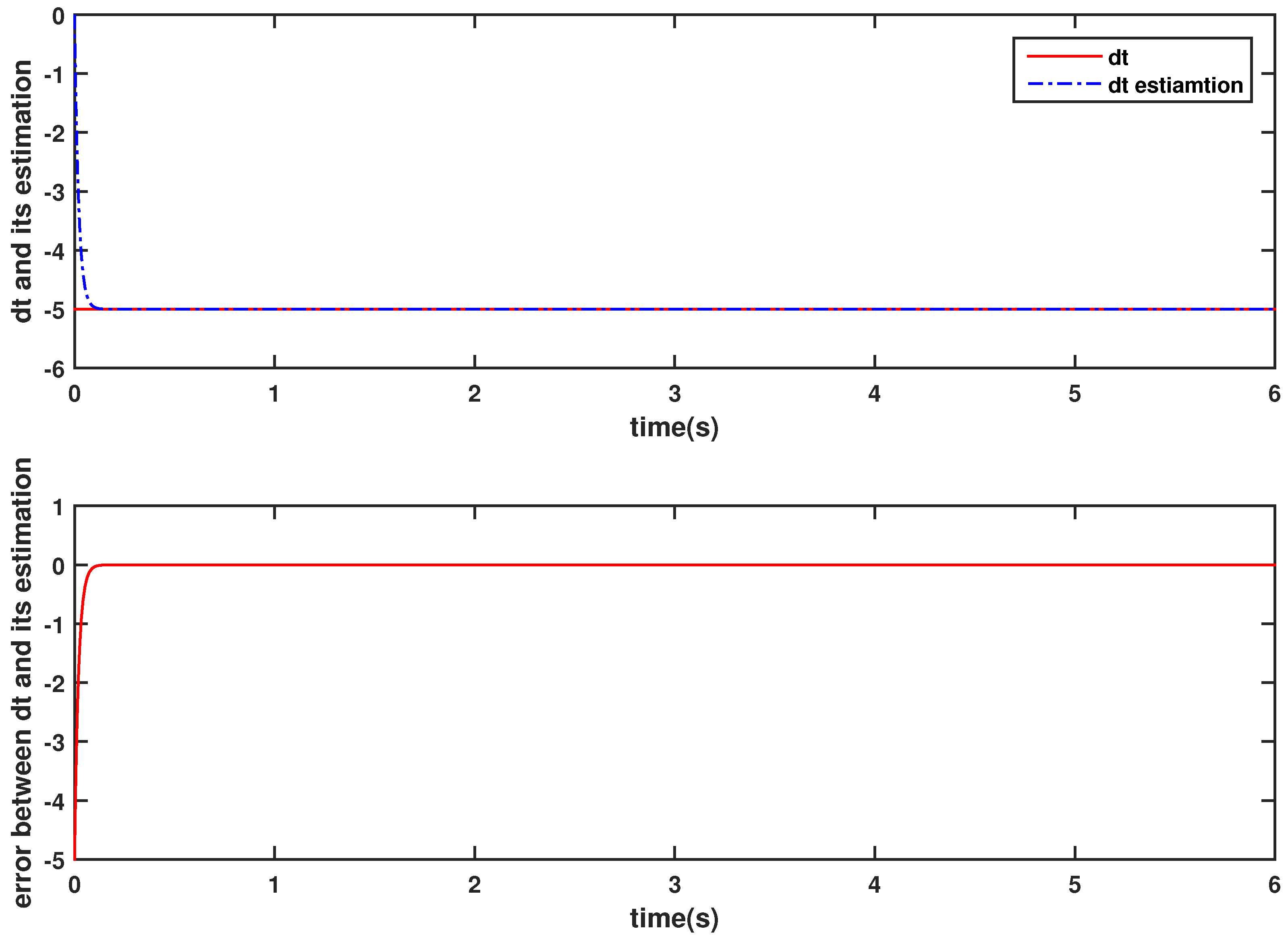
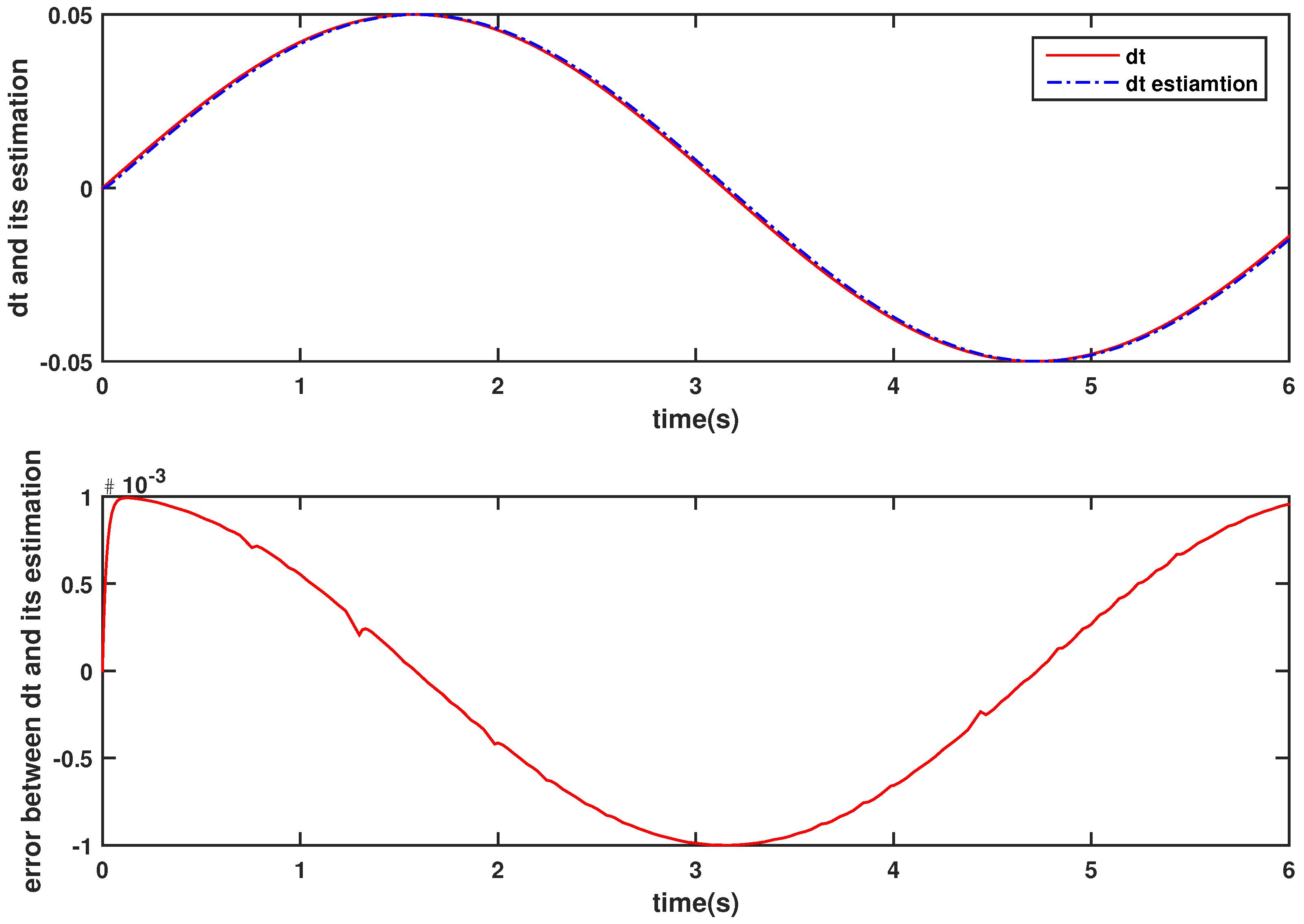
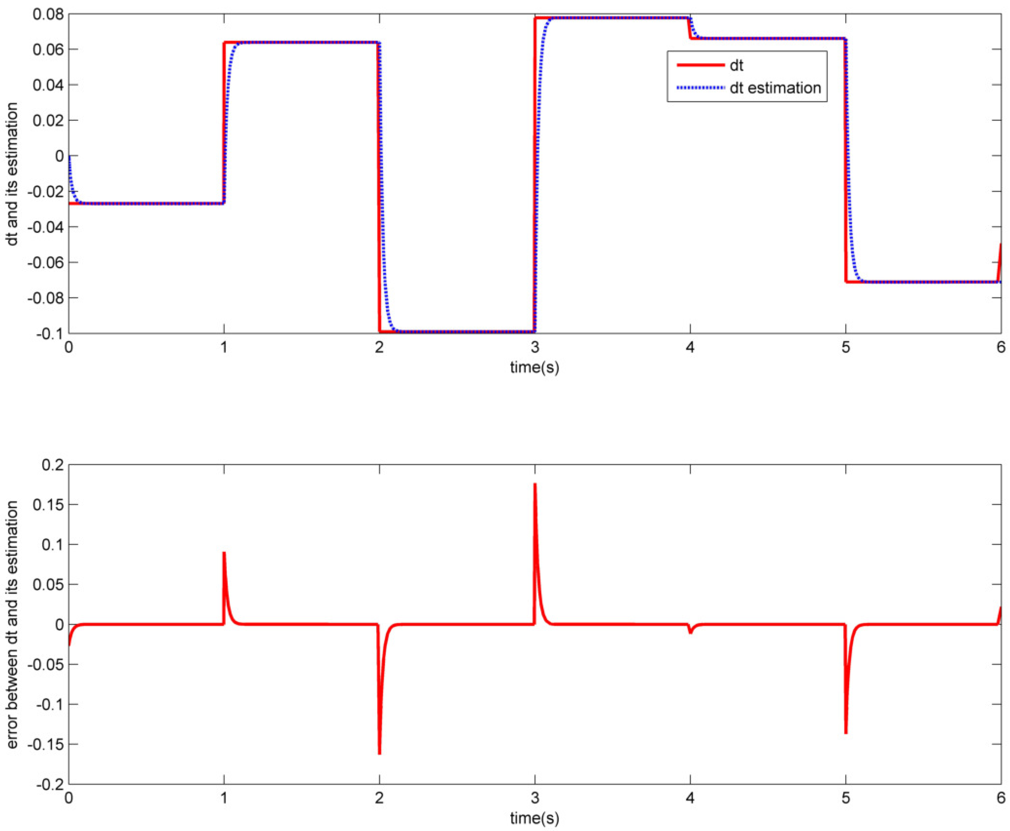
The system modeling takes into account the influence of disturbances on the control system. The unknown disturbance is accurately estimated by using a nonlinear disturbance observer, and the estimated value is used as a feedback signal to provide compensation for the sliding mode controller, effectively restraining the trajectory tracking error caused by the disturbance and improving the anti-interference ability of the system.
(II)
A nonsingular fast terminal sliding mode controller based on nonlinear disturbance observer compensation is proposed for dexterous robot finger control. The nonlinear hyperbolic tangent function is used to replace the symbolic function, which further weakens the chattering problem. Fast and high-precision tracking of the expected trajectory in joint space is achieved.
(III)
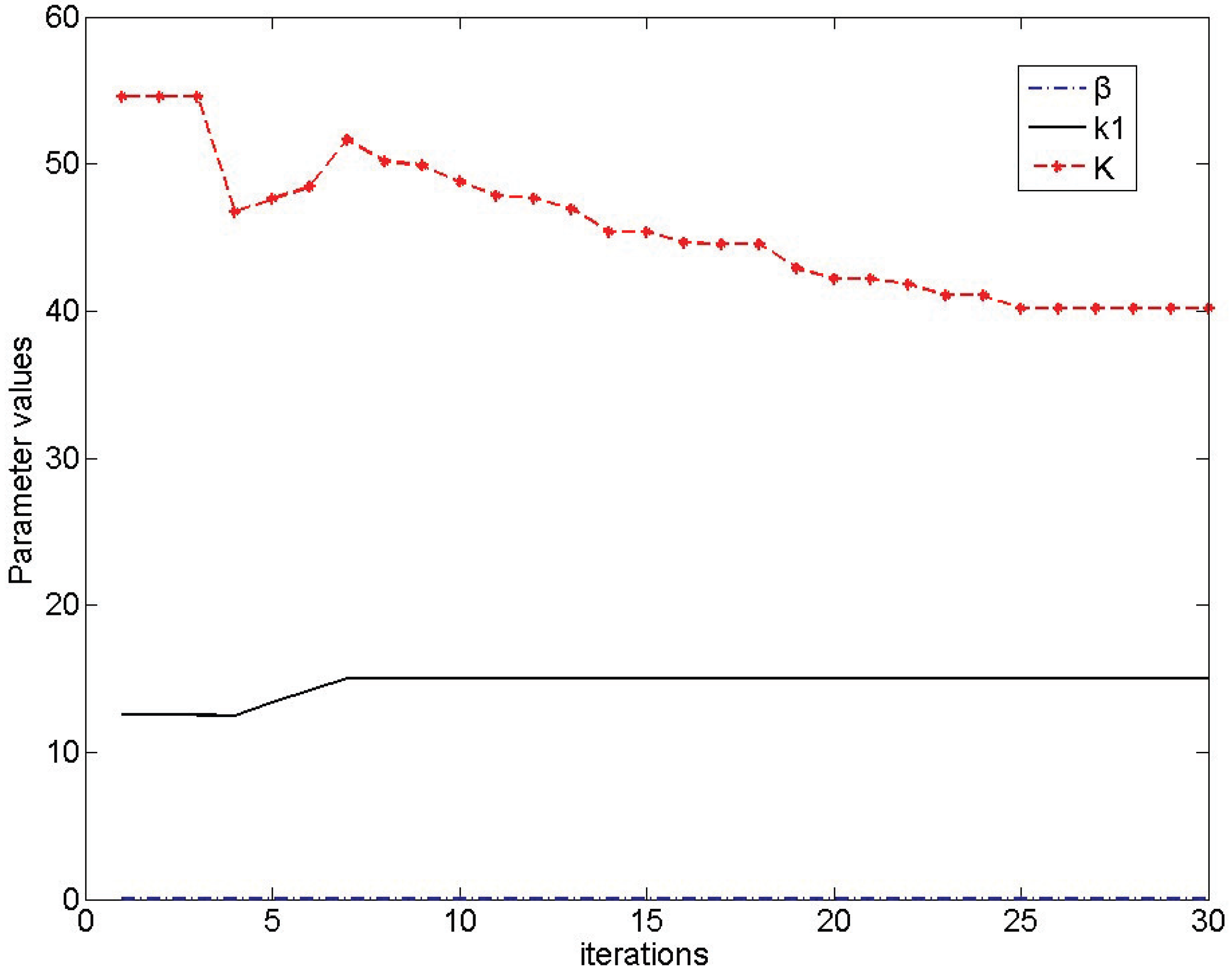
Parameter optimization of the control system is implemented using the PSO algorithm, which improves the overall performance of the controller.
The structure of the paper is as follows. First, a theoretical model of the dexterous hand system is established. Based on this model, the controller is designed, including the design of a nonlinear disturbance observer, the design of a fast continuous nonsingular terminal sliding mode controller with stability proof, and parameter tuning using the PSO algorithm. Then, a detailed comparison of simulation experiments under different controllers is provided to verify the system’s stability, robustness, and tracking performance. Finally, the conclusions of the paper are summarized, and references are also provided.

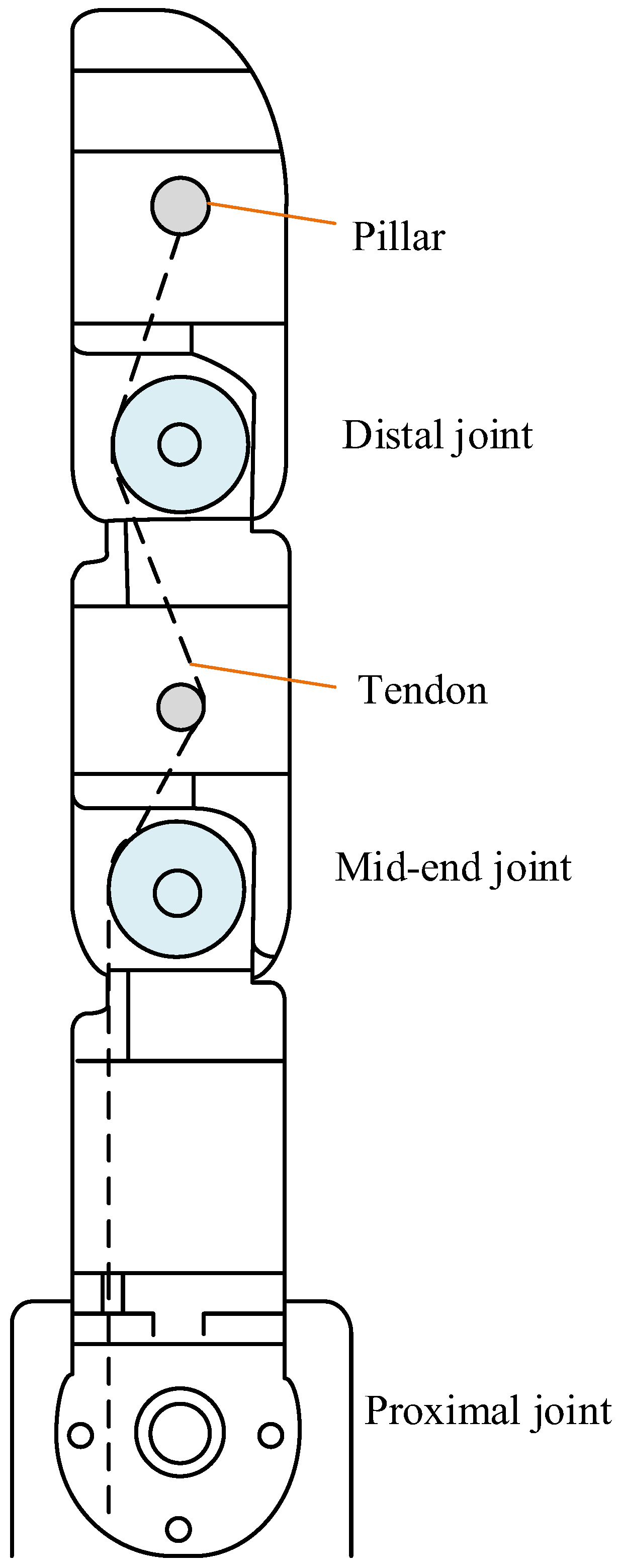
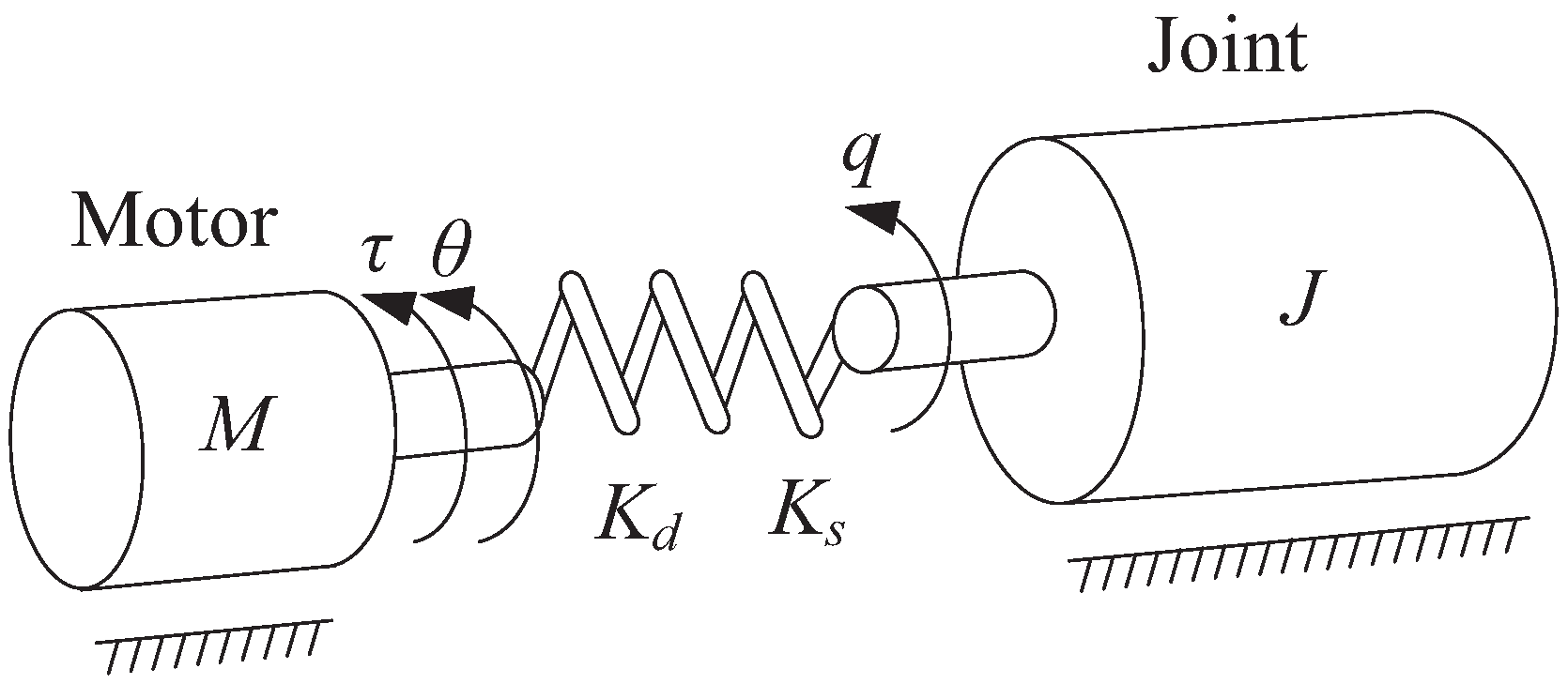
2. System Description

The structure model of a dexterous robotic finger driven by tendons is shown in Figure 1. Every degree of freedom of the finger is driven by the motors. Through the pillar, every motor, which is mounted on the forearm frame, drives the tendons to give pull control. Torsion springs are installed to ensure the return of the fingers.
In the process of tendon-driven finger movement, the power from the motor to the joint is transmitted by the tendon, and the flexibility of the tendon is mainly concentrated on the joint, which can be equivalent to a flexible joint. We simplify the flexible joint into a linear spring for modeling and analysis (see Figure 2). The Lagrange–Euler method can be used to derive the dynamic model of an n-degree-of-freedom cable-driven dexterous finger. Considering joint flexibility, it can be described as
J ( q , t ) q ¨ + C ( q , t ) q ˙ + G ( q , t ) + τ d ( t ) = K s ( θ q ) + K d ( θ ˙ q ˙ )
M ( θ , t ) θ ¨ + D ( θ , t ) θ ˙ + K s ( θ q ) + K d ( θ ˙ q ˙ ) = τ ( t )
where q q ˙ q ¨ are the vectors of joint angle, joint velocity, and joint acceleration; θ θ ˙ θ ¨ are the vectors of angle, angular velocity, and angular acceleration of the motor, respectively; J ( q , t ) denotes the mass–inertia matrix of the joint; C ( q , t ) denotes the Coriolis force and centrifugal force matrix; G ( q , t ) is the gravitational force vector; τ d ( t ) denotes the vector of disturbance torques; and K s K d are the joint stiffness and damping matrices, respectively. τ ( t ) is the output torque of the motor, which is the input of the controller.
By combining Equations (1) and (2), it can be concluded that the dynamic model of a cable-driven dexterous finger driven by an electric motor is as follows.
J ( q , t ) q ¨ + C ( q , t ) q ˙ + G ( q , t ) + M ( θ , t ) θ ¨ + D ( θ ˙ , t ) θ ˙ + τ d = τ
During the operation of the dexterous finger, a change in the posture of the fingertip can cause changes in the load moment of inertia on the joints, and the driving chain is long, which will be influenced by various frictional forces. These factors will bring modeling uncertainty; therefore, it is necessary to estimate the modeling uncertainty.
By introducing a constant diagonal gain matrix J ¯ , (3) can be written as
J ¯ · q ¨ + d = τ
where d = ( J J ¯ ) q ¨ + C ( q , t ) q ˙ + G ( q , t ) + M ( θ , t ) θ ¨ + D ( θ ˙ , t ) θ ˙ + τ d , which denotes a lumped disturbance including all the external disturbances and system uncertainties.

3. Controller Design

3.1. Design of Nonlinear Disturbance Observer

In order to reduce the impact of external interference on the system and improve the control accuracy of the system, an interference observer is introduced to approximate the interference of the system. The nonlinear disturbance observer (NDO) has a brief structure, small computation cost, and high approximation accuracy. The design process of the observer is as follows.

3.1.1. Observer Structure Design

Suppose that
d ^ ˙ = K ( d d ^ )
where d is the actual output of the NDO and d ^ is the estimated output of the NDO, K is the parameter to be designed. Define an auxiliary vector (the internal state vector of NDO)
z = d ^ + K J ¯ q ˙
Differentiating Equation (6) yields
z ˙ = d ^ ˙ + K J ¯ · q ¨
Bringing Equation (4) into Equation (5) yields
d ^ ˙ = K ( d d ^ ) = K ( τ J ¯ q ¨ ) K d ^
By combining Equations (7) and (8), we obtain
z ˙ = K ( τ d ^ )
The nonlinear interference observer is designed as
d ^ = z K J ¯ q ˙ z ˙ = K ( τ d ^ )

3.1.2. Estimation Error Dynamics

Assuming interference and uncertainty change slowly, it can be assumed that d ˙ = 0 . Suppose the observation error is
d ˜ = d d ^
Differentiating Equation (11) yields
d ˜ ˙ = d ˙ d ^ ˙ = d ^ ˙ = z ˙ + K J ¯ · q ¨
We substitute Equation (10) into Equation (11):
d ˜ ˙ = K ( τ z + K J ¯ q ˙ ) + K J ¯ · q ¨ = K ( z K J ¯ q ˙ ) K ( τ J ¯ · q ¨ )

3.1.3. Convergence of Error

We simplify Equation (9), and then the observation error equation is
d ˜ ˙ + K d ˜ = 0
It is solved as
d ˜ ( t ) = d ˜ ( t 0 ) e K t
Thus, d ˜ ( t 0 ) is determined, the error of the observer is exponentially convergent, and the convergence accuracy depends on the parameter K.

3.1.4. Selection of Parameter K

By designing the parameter K, the estimated value d ^ approximates the disturbance and uncertainty terms d.
  • Depending on the dynamic characteristics of the system, an initial value K 0 is selected;
  • We tune the parameter K using simulation or experimental methods, so that the convergence speed of the observer meets the requirements.
  • We consider the accuracy of the system and the energy efficiency of particle swarm optimization parameter K, as shown in Section 3.3.

3.1.5. Proof of Stability of Observer

We design the Lyapunov function V = 1 2 d ˜ T d ˜ and then V ˙ = d ˜ T d ˜ ˙ = d ˜ T ( K d ˜ ) = d ˜ T K d ˜ , because K is a positive parameter; V 0 , so the observer system is stable.

3.2. Design of Fast Continuous Nonsingular Terminal Sliding Mode Controller

3.2.1. Control Input

The sliding mode control law is composed of equivalent control u e q and switching robust control u c t . By making s ˙ = 0 , the equivalent term u e q can be obtained, and then we assume the input u = u e q + u c t . By selecting the fast terminal sliding mode approach law and finding the input u that meets the condition of s s ˙ η | s | , the switching robust term u 1 c t of the sliding mode control law can be obtained.
Assume the tracking error of the joint angle q of the dexterous finger is e = q r q and the tracking error of the angular velocity is e ˙ = q ˙ r q ˙ . The designed fast continuous nonsingular terminal sliding surface is
s = e + β e ˙ γ tanh ( e ˙ ) = e + β sig ( e ˙ ) γ = 0
where q r , q ˙ r are the reference values for the joint angle and its first derivative, β > 0 , 1 < γ < 2 are the parameters of the controller, and tanh ( · ) is a hyperbolic tangent function, which can effectively suppress the buffeting of the input torque signal by replacing the common sign subsection function in the sliding mode control sig ( s ) p = s p sign ( s ) .
Taking the derivative of Equation (16) yields
s ˙ = e ˙ + β γ e ˙ γ 1 e ¨ = 0
We substitute Equation (17) into Equation (4), and the equivalent input of the system is
u e q = J ¯ ( ( β 1 γ 1 e ˙ ) 2 γ + q ¨ r + d ^ )
In order to enable the system’s state to converge and suppress chattering in a finite time, a fast terminal sliding mode approach law is selected:
s ˙ = k 1 s k 2 sig ( s ) p
where 0 < p < 1 , k 1 , k 2 are the controller parameters.
Then, the switched robust control input based on this approach law is
u c t = J ¯ ( k 1 s + k 2 sig ( s ) p )
Based on the principle of equivalent control in the sliding mode, the control input for the joint angle q can be obtained as:
u = u e q + u c t

3.2.2. Proof of Stability and Convergence of Sliding Mode

Theorem 1 ([29]). 
All signals in the system are bounded; the joint angle tracking error and its first derivative converge to zero in finite time, that is,
e 2 Δ = 2 min ( Δ 1 , Δ 2 )
e ˙ ( Δ / β ) 1 1 γ γ
where Δ 1 = d ^ d / k 1 , Δ 2 = ( d ^ d / k 2 ) 1 1 p p .
Define a Lyapunov function as:
V = 1 2 s T s
Then,
V ˙ = s T s ˙
Simultaneously taking Equations (16)∼(21), the first derivative of a fast continuous nonsingular terminal sliding surface can be derived as follows:
s ˙ = e ˙ + β γ e ˙ γ 1 ( β 1 γ 1 e ˙ 2 γ k 1 s k 2 sig ( s ) p + d ^ d )
Substituting Equation (26) into (25) yields
V ˙ = β γ e ˙ 1 γ 1 ( d ^ d ) s k 1 β γ e ˙ 1 γ 1 s 2 k 2 β γ e ˙ 1 γ 1 sig ( s ) p + 1
Equation (27) can be described in two forms:
V ˙ = ( k 1 β γ e ˙ γ 1 β γ e ˙ γ 1 ( d ^ d ) s 1 ) s 2 k 2 β γ e ˙ γ 1 s p + 1
V ˙ = k 1 β γ e ˙ γ 1 s 2 ( k 2 β γ e ˙ γ 1 β γ e ˙ γ 1 ( d ^ d ) s i g ( s ) p ) s p + 1
For (28), if k 1 β γ e ˙ 1 γ 1 β γ e ˙ 1 γ 1 ( d ^ d ) s 1 is positive definite, then V ˙ < 0 . For (29), if k 2 β γ e ˙ 1 γ 1 β γ e ˙ 1 γ 1 ( d ^ d ) s i g ( s ) p is positive definite, then V ˙ < 0 is also available.
Lemma 1 ([30]). 
If there is a Lyapunov function V that satisfies the following equation
V ˙ + ε V + ω V δ 0
where ϵ > 0 , ω > 0 , 0 < δ < 1 , then the stability time under this condition is
τ S ε 1 ( 1 δ ) 1 ln ( 1 + ε ω 1 V 0 1 δ )
where V 0 is the initial condition of V 1 .
According to Theorem 1 and Lemma 1, the sliding surface (16) is stable and converges to a certain region within a finite time:
s β γ e ˙ γ 1 ( d ^ d ) / β γ e ˙ γ 1 k 1 = d ^ d / k 1 = Δ 1
s ( β γ e ˙ γ 1 ( d ^ d ) / β γ e ˙ γ 1 k 2 ) 1 / p = ( d ^ d / k 2 ) 1 / p = Δ 2
By organizing the two Formulas (32) and (33), we can conclude that:
s Δ = min ( Δ 1 , Δ 2 )

3.2.3. The Proof of the Convergence of the Tracking Error and the First Derivative of the Tracking Error

We rewrite Equation (16) as:
e + ( β s s i g ( e ˙ ) γ ) s i g ( e ˙ ) γ = 0
For s Δ , when β s / s i g ( e ˙ ) γ > 0 , Equation (35) is kept in the form of TSM. Therefore, the first derivative of the tracking error is converged to the region in finite time:
e ˙ ( Δ / β ) 1 / γ
Based on Equations (35) and (36), it can be seen that the tracking error converges in finite time as
e β s i g e ˙ γ + s 2 Δ

3.3. Parameter Tuning of NDO-NFTSM Based on PSO Algorithm

3.3.1. Selection of Evaluation Function

Taking into account the stability, the accuracy of the system, and the energy efficiency, the evaluation function is
J ( p ) = 0 ( w 1 | e ( t ) | + w 2 | u ( t ) | ) d t
where e ( t ) is the system error, u ( t ) is the input control, and w 1 and w 2 are the weights. The smaller the value of J ( p ) (fitness function), the closer the corresponding particles to the global optimal solution. The value of the evaluation function will gradually decrease as the algorithm runs.

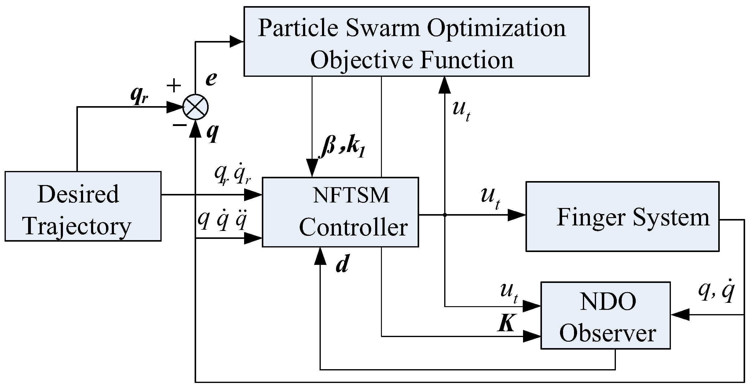
3.3.2. System Structure of NDO-NFTSM Control

The system structure of NDO-NFTSM control based on the PSO algorithm is shown below (see Figure 3).

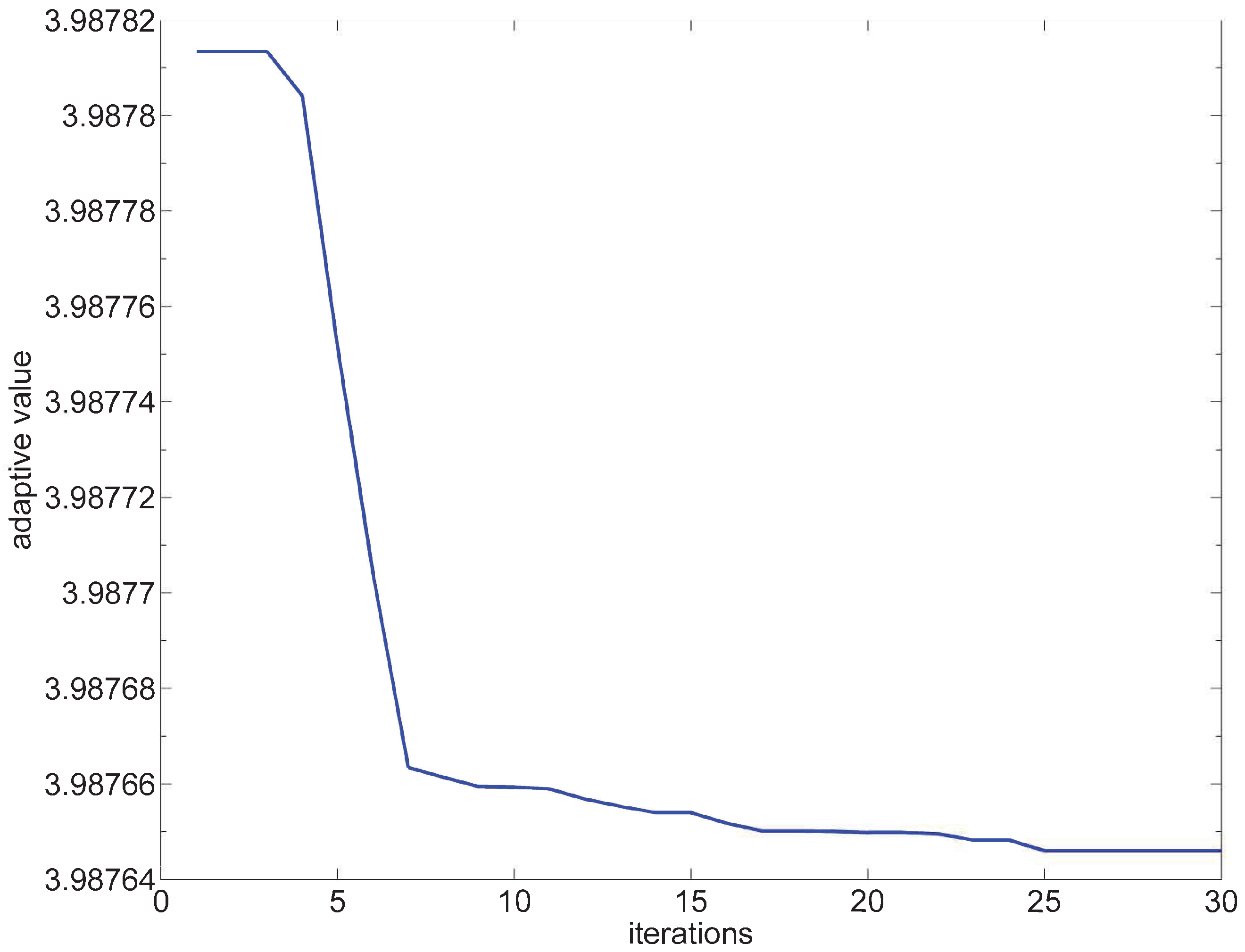
3.3.3. NDO-NFTSM Process Based on PSO Algorithm

The NDO-NFTSM process based on the PSO algorithm is shown in Figure 4.

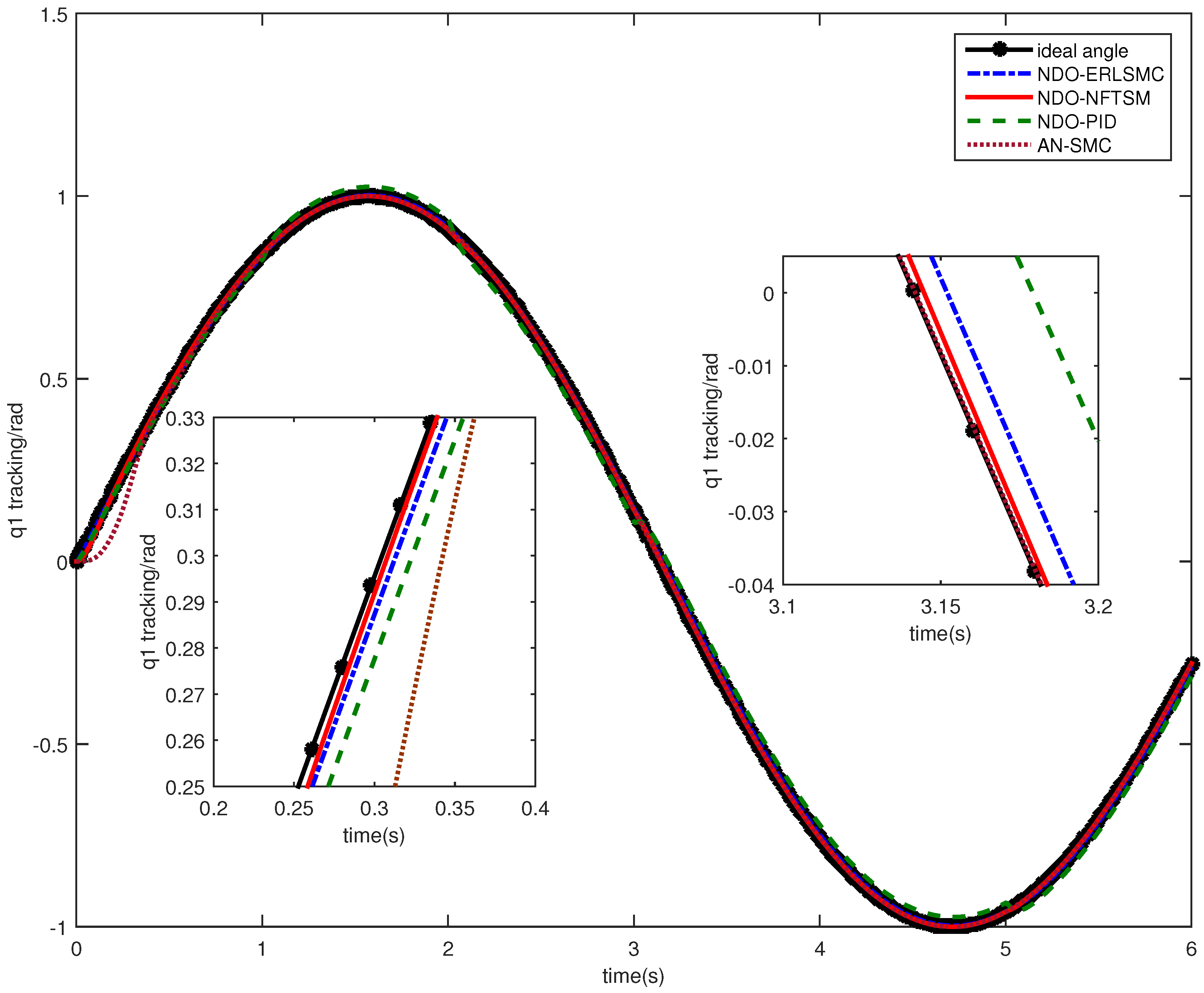
4. Numerical Simulations

To test the effectiveness of the controller, it is assumed that the desired trajectory of the dexterous finger joint angle q 1 is a sine signal (due to the similar control effects of each joint, to simplify the analysis, only one independent joint is analyzed in this paper) and the other conditions are 0. Gaussian noise signals with the mean value of 0 and variance of 0.01 are adopted as the jamming torque, and the simulation time is 6 s.
There are three parameters that need to be tuned, namely, the sliding mode controller parameters β and k 1 and the disturbance observer parameter K. The PSO algorithm is used to tune the parameters, which have a population of parameters of 20, a population size of 8, a self-learning factor of 0.8, a population learning factor of 0.5, and an inertia factor range of [0.4, 0.9]. The parameter-tuning effect is shown in Figure 4 and Figure 5. When iterating 30 times, the particle swarm found the optimal value and maintained it subsequently. (see Figure 5 and Figure 6).
The tuning results for parameters β , k 1 , and K are 0.010, 15.0000, and 40.2050. The optimal fitness value is 3.988.
We use four types of controllers, namely, NDO-NFTSM, NDO-ERLSMC (exponent reaching law sliding mode control), NA-SMC (the neural network adaptive sliding mode control) [31], and classical NDO-PID (Proportional Integral Differential), to conduct comparative simulation experiments and verify the effectiveness. The parameters of the four controllers are shown in Table 1.
As shown in Figure 7, all four controllers can effectively suppress external interference, achieving tracking of the reference trajectory in finite time. From the perspective of the trajectory tracking effect, the tracking accuracy of the controller in this paper is superior to the other three controllers. In an enlarged view, it can be seen that the tracking speed of the NDO-NFTSM controller is the fastest, and it can quickly track the reference trajectory from the initial state to around 0.3 s. Afterwards, it maintains a stable tracking state and has strong anti-interference ability. The performance of the NDO-ERLSMC controller is lower than that of the NDO-NFTSM, and the tracking performance of the NA-SMC is relatively poor before 0.4 s, indicating that this is the parameter adaptation phase. After that, the tracking accuracy improves significantly. In comparison, the performance of the NDO-PID is inferior.
In order to verify uncertainty, in this study, the sources of uncertainty are the moment of inertia of the motor and the external load disturbance. The moment of inertia J is modeled as an interval uncertainty parameter with a range of J [ J min , J max ] , which are J min = 0.8 J 0 , J max = 1.2 J 0 . The performance of the error indicators MAE (Mean Absolute Error) and MSE (Mean Square Error) under different moments of inertia J is shown in Table 2 below.
In order to verify system disturbance capability, suppose d t = 5 , d t = 0.05 s i n ( t ) , and d t is Gaussian white noise, respectively. The simulation results are shown in Figure 8, Figure 9 and Figure 10.
Figure 8 shows that under constant disturbance, the system can quickly converge and maintain stability, demonstrating strong anti-disturbance capability; Figure 9 shows that under sinusoidal disturbance, the system can effectively track the desired trajectory with small tracking errors, indicating good suppression of periodic disturbances; and Figure 10 shows that under Gaussian white noise disturbance, the system still maintains high tracking accuracy, showing strong robustness to random disturbances.
Under different control methods, the quantification of the error index under Gaussian noise is shown in Table 3 below.
From Table 3, it can be observed that the MSE and MAE of the NDO-NFTSM system are lower than the others, indicating that the NDO-NFTSM system has higher accuracy and stability.
Figure 11 shows the output torque response of four controllers. It can be seen that the control torque in this paper has a significant change in the initial stage and then tends to stabilize without an obvious chattering phenomenon. The NDO-ERLSMC controller is optimal in the initial stage with the smallest change in control torque, but its subsequent performance is worse than that of the NDO-NFTSM controller. The AN-SMC controller also performs well, and the NDO-PID controller has the maximum amplitude of torque, which indicates that its torque performance is the worst.

5. Conclusions

A fast terminal sliding mode control algorithm based on a nonlinear disturbance observer is proposed for the joint trajectory tracking problem of dexterous hand fingers, and the particle swarm optimization algorithm is used for parameter tuning to achieve optimal control of trajectory tracking of dexterous hand fingers.
(1)
A dynamic model of a dexterous cable-driven robot finger was established by equating the flexibility effect of rope drive with the joint, and the simulation results also proved the effectiveness of the model.
(2)
Utilizing NDOB to estimate unknown interference online and compensating for interference in the control system effectively suppresses the chattering of the system.
(3)
By tuning the controller parameters using the PSO algorithm, it makes parameter adjustment more convenient and improves the performance of the control system.
(4)
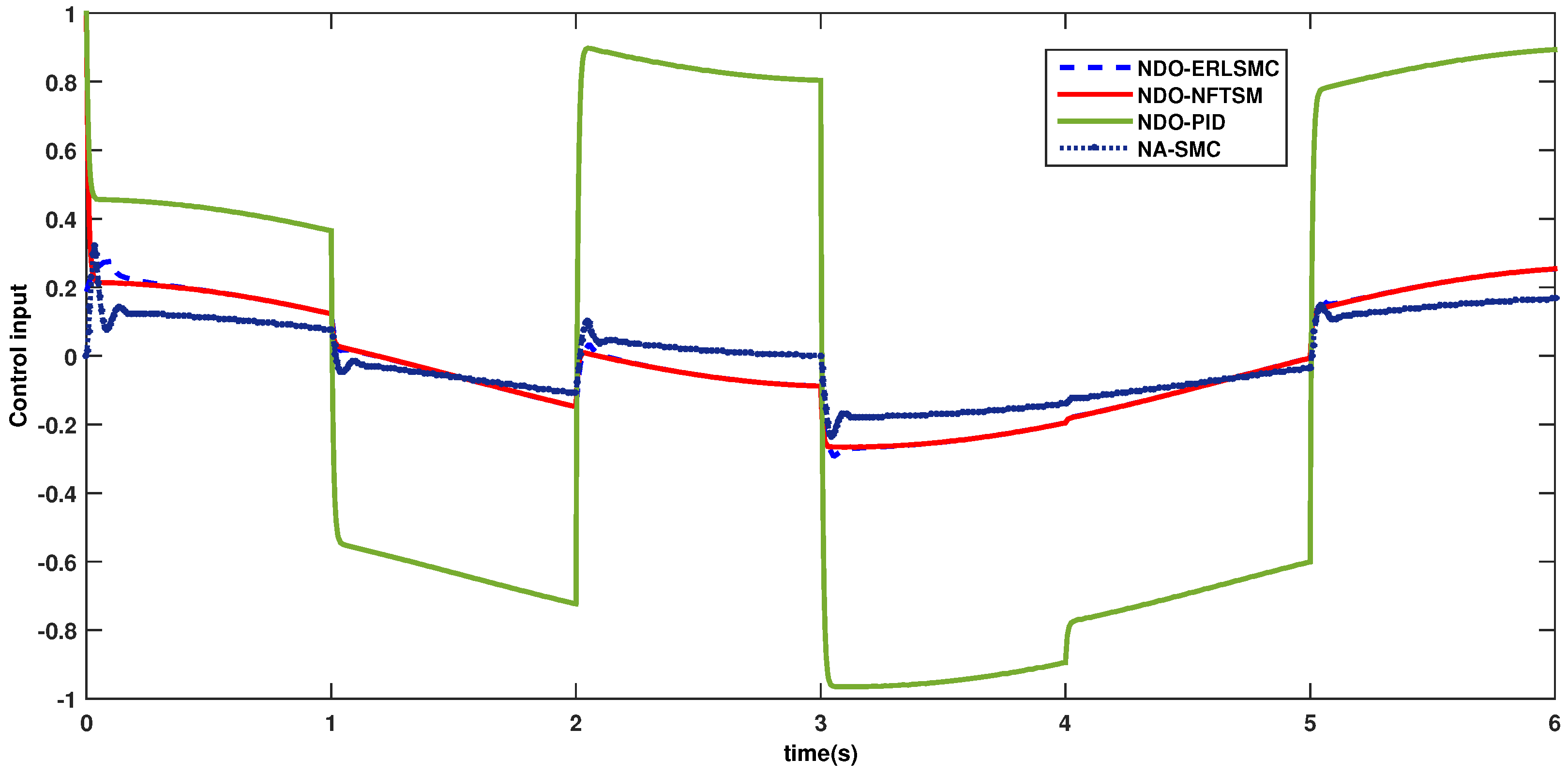
FNTSMC is introduced to accelerate the rate of convergence of the control law, so that the system tracking error can converge to the specified region in a finite time. The simulation results show that the control algorithm in this paper has a faster convergence rate and higher tracking accuracy than the others.

Author Contributions

Conceptualization, J.P. and J.C.; data curation, J.P.; formal analysis, J.P.; funding acquisition, J.P. and J.C.; investigation, J.P. and J.C.; methodology, J.P. and J.C.; project administration, J.P.; software, J.P. and J.C.; supervision, J.P.; validation, J.C.; visualization, J.P. and J.C.; writing—original draft, J.P. and J.C.; writing—review and editing, J.P. and J.C. All authors have read and agreed to the published version of the manuscript.

Funding

This research was funded by the research project of 2020 Anhui Polytechnic University’s research program, grant number Xjky2020002.

Data Availability Statement

The data presented in this study are available on request from the corresponding author.

Conflicts of Interest

The authors declare no conflicts of interest.

Abbreviations

The following abbreviations are used in this manuscript:
NFTSMnonsingular fast terminal sliding mode
ERLSMCexponent reaching law sliding mode control
PIDProportional Integral Differential
NA-SMCneural network adaptive sliding mode control
NDOnonlinear disturbance observer
PSOparticle swarm optimization
MSEMean Square Error
MAEMean Absolute Error

References

  1. Yoshikawa, T. Multifingered robot hands: Control for grasping and manipulation. Annu. Rev. Control. 2010, 34, 199–208. [Google Scholar] [CrossRef]
  2. Ozawa, R.; Tahara, K. Grasp and dexterous manipulation of multi-fingered robotic hands: A review from a control view point. Adv. Robot. 2017, 31, 1030–1050. [Google Scholar] [CrossRef]
  3. Grebenstein, M.; Albu-Schäffer, A.O.; Bahls, T.; Chalon, M.; Eiberger, O.; Friedl, W.; Gruber, R.; Haddadin, S.; Hagn, U.; Haslinger, R.; et al. The DLR hand arm system. In Proceedings of the 2011 IEEE International Conference on Robotics and Automation, Shanghai, China, 9–13 May 2011; pp. 3175–3182. [Google Scholar] [CrossRef]
  4. King, J.P.; Bauer, D.; Schlagenhauf, C.; Chang, K.H.; Moro, D.; Pollard, N.S.; Coros, S. Design. Fabrication, and Evaluation of Tendon-Driven Multi-Fingered Foam Hands. In Proceedings of the 2018 IEEE-RAS 18th International Conference on Humanoid Robots (Humanoids), Beijing, China, 6–9 November 2018; pp. 1–9. [Google Scholar] [CrossRef]
  5. Shadow Robot Company. Shadow Dexterous Hand Technical Specification; Shadow Robot Company: London, UK, 2022; Available online: https://www.shadowrobot.com/wp-content/uploads/2024/06/20240610-UPDATED-shadow_dexterous_hand_e_technical_specification.pdf (accessed on 1 January 2025.).
  6. Fan, S.; Gu, H.; Zhang, Y.; Jin, M.H.; Liu, H. Research on adaptive grasping with object pose uncertainty by multi-fingered robot hand. Int. J. Adv. Robot. Syst. 2018, 15, 1729881418766783. [Google Scholar] [CrossRef]
  7. Li, X.; Chen, Z.; Ma, C. Optimal grasp force for robotic grasping and in-hand manipulation with impedance control. Assem. Autom. 2021, 41, 208–220. [Google Scholar] [CrossRef]
  8. Shahriari, E.; Birjandi, S.A.B.; Haddadin, S. Passivity-based Adaptive Force-Impedance Control for Modular Multi-Manual Object Manipulation. IEEE Robot. Autom. Lett. 2022, 7, 2194–2201. [Google Scholar] [CrossRef]
  9. Zhang, T.; Jiang, L.; Fan, S.; Wu, X.; Feng, W. Development and experimental evaluation of multi-fingered robot hand with adaptive impedance control for unknown environment grasping. Robotica 2014, 34, 1168–1185. [Google Scholar] [CrossRef]
  10. Jalani, J.; Mahyuddin, M.N.; Herrmann, G.; Melhuish, C. Active robot hand compliance using operational space and Integral Sliding Mode Control. In Proceedings of the 2013 IEEE/ASME International Conference on Advanced Intelligent Mechatronics, Wollongong, Australia, 9–12 July 2013; pp. 1749–1754. [Google Scholar] [CrossRef]
  11. Herrmann, G.; Jalani, J.; Mahyuddin, M.N.; Herrmann, G.; Melhuish, C. Robotic hand posture and compliant grasping control using operational space and integral sliding mode control. Robotica 2016, 34, 2163–2185. [Google Scholar] [CrossRef]
  12. Labbadi, M.; Cherkaoui, M. Robust adaptive backstepping fast terminal sliding mode controller for uncertain quadrotor UAV. Aerosp. Sci. Technol. 2019, 93, 105306. [Google Scholar] [CrossRef]
  13. Zaihidee, F.M.; Mekhilef, S.; Mubin, M. Robust Speed Control of PMSM Using Sliding Mode Control (SMC)—A Review. Energies 2019, 12, 1669. [Google Scholar] [CrossRef]
  14. Jung, S. Improvement of Tracking Control of a Sliding Mode Controller for Robot Manipulators by a Neural Network. Int. J. Control. Autom. Syst. 2018, 16, 937–943. [Google Scholar] [CrossRef]
  15. Man, Z.; Paplinski, A.P.; Wu, H.R. A robust MIMO terminal sliding mode control scheme for rigid robotic manipulators. IEEE Trans. Autom. Control. 1994, 39, 2464–2469. [Google Scholar] [CrossRef]
  16. Feng, Y.; Yu, X.; Man, Z. Non-singular terminal sliding mode control and its application for robot manipulators. Automatica 2002, 38, 2159–2167. [Google Scholar] [CrossRef]
  17. Boukattaya, M.; Mezghani, N.; Damak, T. Adaptive nonsingular fast terminal sliding-mode control for the tracking problem of uncertain dynamical systems. ISA Trans. 2018, 77, 1–19. [Google Scholar] [CrossRef] [PubMed]
  18. Chen, Z.S.; Wang, X.S.; Cheng, Y.H. Considering disturbance and input saturation of the manipulator continuous nonsingular fast terminal sliding mode control. Control. Decis. 2022, 37, 903–912. [Google Scholar]
  19. Yi, S.; Zhai, J. Adaptive second-order fast nonsingular terminal sliding mode control for robotic manipulators. ISA Trans. 2019, 90, 41–51. [Google Scholar] [CrossRef]
  20. Ma, X.; Xu, Y.; Zhang, L.; Bai, J. Model-Free Generalized Super-Twisting Fast Terminal Sliding Mode Control for Permanent Magnet Synchronous Motors. Symmetry 2025, 17, 18. [Google Scholar] [CrossRef]
  21. Yao, Y.; Ding, L.; Ma, R.; Wang, Y.Y. Robust Control for a Cable-driven Aerial Manipulator with Joint Flexibility in Joint Space. Control. Decis. 2023, 38, 9–17. [Google Scholar] [CrossRef]
  22. Sun, G.F.; Zhao, E.Q.; Zhang, G.J.; Huang, M. Non-singular fast terminal sliding mode control of manipulator based on disturbance observe compensation. Control. Theory Appl. 2022, 39, 1506–1515. [Google Scholar] [CrossRef]
  23. Zhao, Z.; He, X.; Ki, A.C. Boundary Disturbance Observer-Based Control of a Vibrating Single-Link Flexible Manipulator. IEEE Trans. Syst. Man Cybern. Syst. 2021, 51, 2382–2390. [Google Scholar] [CrossRef]
  24. Fang, X.; Zhang, C.; Zhang, C.; Lu, Y.; Xu, G.; Shang, Y. Differential Flatness Based Unmanned Surface Vehicle Control: Planning and Conditional Disturbance-Compensation. Symmetry 2024, 16, 1118. [Google Scholar] [CrossRef]
  25. Bu, X.; Xiaoyan, W.; Yongxing, C.; Ruiyang, B. Nonlinear-disturbance-observer-based sliding mode backstepping control of hypersonic vehicles. Control. Theory Appl. 2015, 31, 1473–1479. [Google Scholar] [CrossRef]
  26. Yu, J.; Chen, M.; Jiang, C.S. Adaptive sliding mode control for nonlinear uncertain systems based on disturbance observer. Control. Theory Appl. 2014, 31, 993–999. [Google Scholar]
  27. Wang, X.; Guo, W.; Wei, M. Parameter Tuning of Fractional-Order PID Sliding Mode Control Based on Particle Swarm Optimization. Meas. Control. Technol. 2017, 36, 63–66. [Google Scholar]
  28. Duan, X.J.; Zhu, F.Y.; Liu, X.Q. Fuzzy Neural Network Sliding Mode Anti-swing Control for Tower Crane Based on PSO. Mach. Tool Hydraul. 2016, 44, 155–159. [Google Scholar]
  29. Nekoukar, V.; Erfanian, A. Adaptive fuzzy terminal sliding mode control for a class of MIMO uncertain nonlinear systems. Fuzzy Sets Syst. 2011, 179, 34–49. [Google Scholar] [CrossRef]
  30. Wang, Y.; Zhu, K.; Chen, B.; Jin, M. Model-free continuous nonsingular fast terminal sliding mode control for cable-driven manipulators. ISA Trans. 2020, 98, 483–495. [Google Scholar] [CrossRef]
  31. Liu, J. Sliding Mode Variable Structure Control MATLAB Simulation, 3rd ed.; Tsinghua University Press: Beijing, China, 2015. [Google Scholar]
Figure 1. Model of dexterous finger structure driven by tendon.
Symmetry 17 00560 g001
Figure 2. Simplified model of joint.
Symmetry 17 00560 g002
Figure 3. System structure of NDO-NFTSM control based on PSO algorithm.
Symmetry 17 00560 g003
Figure 4. The NDO-NFTSM process based on the PSO algorithm.
Symmetry 17 00560 g004
Figure 5. Optimal individual fitness value.
Symmetry 17 00560 g005
Figure 6. Parameter optimization curve.
Symmetry 17 00560 g006
Figure 7. Controller tracking performance comparison.
Symmetry 17 00560 g007
Figure 8. Step signal interference d t and its tracking effect.
Symmetry 17 00560 g008
Figure 9. Sinusoidal signal interference d t and its tracking effect.
Symmetry 17 00560 g009
Figure 10. Gaussian noise signal interference d t and its tracking effect.
Symmetry 17 00560 g010
Figure 11. Joint torque response curves.
Symmetry 17 00560 g011
Table 1. Controller parameters comparison.
ControllerParameters
NDO-NFTSM (the proposed controller) β  = 0.01, K = 40.205, γ  = 1.5, p = 0.1, k 1  = 15, k 2  = 400
NDO-ERLSMCc = 15, K = 40.205
NA-SMCc = 15, γ 1  = 0.05, η  = 0.1
NDO-PID k p  = 50, k i  = 0.5, k d  = 2
Table 2. Error indicators under different J values.
Error Indicator 0.8 J 0 J 0 1.2 J 0
MSE0.05230.04790.0446
MAE0.09420.08730.0784
Table 3. Error indicators under different controllers.
Error IndicatorNDO-NFTSMNDO-ERLSMCNA-SMCNDO-PID
MSE1.4417 × 10−41.8118 × 10−42.5063 × 10−42.2701 × 10⁻⁴
MAE0.00880.01020.01270.0091
Disclaimer/Publisher’s Note: The statements, opinions and data contained in all publications are solely those of the individual author(s) and contributor(s) and not of MDPI and/or the editor(s). MDPI and/or the editor(s) disclaim responsibility for any injury to people or property resulting from any ideas, methods, instructions or products referred to in the content.

