Article

Multi-Objective Approach for Wide-Area Damping Control Design

by
Murilo E. C. Bento
Department of Electrical Engineering, Federal University of Rio de Janeiro, Rio de Janeiro 21941-909, Brazil
Symmetry 2025, 17(11), 1781; https://doi.org/10.3390/sym17111781
Submission received: 10 September 2025 / Revised: 9 October 2025 / Accepted: 17 October 2025 / Published: 22 October 2025
(This article belongs to the Special Issue Symmetry in Optimal Control and Applications)

Abstract

Poorly damped low-frequency oscillation modes can destabilize power systems in the event of contingencies. Advances in the widespread use of phasor measurement units (PMUs) in power systems have led to the development of wide-area damping controllers (WADCs) capable of ensuring good damping ratios for these oscillation modes. However, cyberattacks or communication failures affect PMU data and can cause WADC malfunctions. Poor WADC operation can even destabilize the power system. Therefore, this paper proposes the design of a WADC robust to communication failures through a multi-objective optimization model requiring high damping ratios for the closed-loop system and the existence of a symmetric and positive defined matrix to guarantee the stability of the system. Bio-inspired algorithms can solve this proposed multi-objective optimization model, and the stellar oscillation optimizer proved to be a bio-inspired algorithm with an excellent ability to reach an optimal solution. Case studies show that defining the limiting values of the WADC time constants and the existence of this symmetric, positive-definite matrix are beneficial for good system dynamic performance.

1. Introduction

Power systems often face challenges in ensuring the desired supply of quality electricity to consumer centers [1]. Variability in energy demand, the interconnection of large generation centers by long transmission lines, the incorporation of new energy sources, and the increasing number of faults and incidents are some of the current operational challenges of modern power systems. Therefore, control projects are frequently proposed and implemented to improve the dynamic performance of power systems [1]. Xiong et al. [2] developed a control scheme to ensure the stability of power systems in major emergencies. Huang et al. [3] developed a hierarchical robustness strategy to address voltage and frequency deviation in islanded AC microgrids. Liu et al. [4] developed a technique using fault current limiters to treat commutation failure in power systems. Huang et al. [5] developed a new sliding mode controller to ensure stability and good transient stability indices of power systems. Song et al. [6] developed a new control to suppress low-frequency oscillations in power systems with wind generation. Ban et al. [7] propose a new control strategy for bus voltage regulation and SoC balance in microgrids.
Damping controller design is one of the most common control projects in small-signal angular stability studies of power systems. Oscillation modes associated with the electromechanical variables of power systems are in the frequency range of 0.1 to 2 Hz and, in most cases, have low damping ratios. The lower these damping ratios, the greater the oscillations in the system’s electrical quantities and the greater the system’s vulnerability to instability in the event of contingencies [8].
Power system stabilizers (PSSs) are traditional oscillation mode damping controllers designed and implemented to send control signals to automatic voltage regulators (AVRs) of synchronous generators [8]. A variety of PSS design techniques are presented in the literature, and their performance in improving signal damping is remarkable. De Campos et al. [9] develop a technique based on Linear Matrix Inequalities (LMIs) to obtain PSS parameters. Abido [10] presents a method based on Particle Swarm Optimization (PSO) for the robust design of a PSS. Bento et al. [11] propose a PSS design by a method based on the linear quadratic regulator (LQR). Metaheuristics such as genetic algorithm [12], bat algorithm [13], ant colony optimization [14], and marine predator algorithm [15] are recommended by the authors in the design of PSS, and the reported results are well detailed and satisfactory. PSSs have proven effective for many years but have shown limited effect in recent years in modern systems due to several factors. The expansion of the interconnection of large power systems has increased the number of inter-area oscillation modes with very low damping ratios, and PSSs are not effective for these inter-area modes due to the low observability of the system since PSSs receive and send control signals only to the synchronous generator to which they are connected.
The increased use of phasor measurement units (PMUs) due to technological advances has brought various benefits to the monitoring [16] and control [17] of power systems. PMUs collect voltage and current measurements in real time at impressive sampling rates, thus providing a snapshot of the system’s dynamics [18]. Furthermore, this PMU data can be acquired from different points of the system where the PMU is installed, facilitating increased system observability [19].
The benefits of PMUs have also extended to power system control due to improved observability and high data transmission rates. Researchers have developed wide-area damping controllers (WADCs), which utilize data from PMUs at different locations in the system and produce control signals for the AVRs [20]. Various techniques have been presented by the scientific community for the design of a WADC [21]. Zhang and Bose [17] presented a method based on LMIs. Bento [22] proposes an LQR-based technique for the design of a robust WADC. Mukherjee et al. [23] proposed the design of a WADC using reinforcement learning. Gupta et al. [24] proposed using reinforcement learning and deep neural networks to design a WADC. Ranjbar et al. [25] developed a method using Thevenin impedance and the CART technique for the design of a WADC. Metaheuristics such as PSO [26,27], greylag goose optimization [28], firefly algorithm [29], genetic algorithm [30,31], grey wolf optimizer [32], mountain gazelle optimizer [33], African vultures optimization [34], marine predators algorithm [35], and crow search algorithm [36] are also widely used in the design of this controller. Researchers have shown that WADCs can significantly increase the damping ratios of inter-area oscillation modes. Thus, the combined use of PSSs and a WADC can improve system performance requirements in small-signal stability studies. Furthermore, a well-defined optimization model can be solved by any metaheuristic.
Although the benefits of the WADC are notable and well documented, implementation challenges arise due to the vulnerability of communication channels to cyberattacks or communication failures. False data injection (FDI) attacks and denial-of-service attacks are a concern in operation centers that rely on PMU data for various applications. WADCs, for example, can malfunction or even destabilize a power system. There is some promising work addressing cyberattacks on WADC channels. Zhang and Vittal [37] propose turning off the WADC when a communication failure is identified, and thus the system operates only with local controls. Naguru [38] proposes a detection and correction matrix so that the WADC is able to tolerate different communication failures. Sarkar et al. [39] propose a dual input and single output for the operation of the WADC, and when a communication failure occurs, the WADC operates as a single input and single output. Bento [40] proposed a technique to address permanent failures in a WADC. Yao et al. [41] developed a WADC capable of handling deception attacks. Patel et al. [42] proposed a WADC with a dynamic loop where the input and output signals are dynamically changed to deal with cyberattacks. Zhang and Vittal [43] propose a structure of redundancy of communication channels to deal with communication failures. A relevant group of researchers have developed WADC control strategies to deal with FDI attacks. Liu et al. [44] developed a Markov game to deal with FDI attacks. Zhao et al. [45] combined goal representation heuristic dynamic programming and a linear state estimator to develop a resilient adaptive WADC capable of tolerating FDI attacks. Sun et al. [46] proposed a mechanism for WADC’s resilience to FDI attacks through a non-intrusive data verification technique that uses a deep convolutional neural network and an adaptive variational autoencoder. Vavdareh et al. [47] proposed and compared two tools to mitigate FDI attacks: (i) a multi-agent control strategy and (ii) a neural-network-based autoencoder. Kumar et al. [48] proposed applying a random forest classifier to detect and mitigate FDI attacks in the operation of a WADC. Saini and Bhui [49] developed a technique using a support vector machine and semi-supervised generative adversarial network to guarantee the security of a WADC against cyberattacks. Saini et al. [50] developed a technique using an unscented Kalman filter and autoencoder to detect dynamic attacks in WADCs. Zhao et al. [51] proposed mitigating strong attacks through a multiple-controller switching technique. Li et al. [52] developed a stochastic game theoretic framework to address cyberattacks on WADC channels. Zhao et al. [53] developed a robust subspace tracking to mitigate sparse attack in WADCs. Zhao et al. [54] developed a method to quantify the resilience of WADCs to cyberattacks. These studies are interesting, but the researchers still identified limitations that require further research.
In LMI-based damping control designs, the search for a symmetric, positive-definite matrix ensures the stability of the dynamic system. Various LMI-based techniques are available in the literature for damping control design [55,56]. However, one of the difficulties reported by the authors is determining this symmetric, positive-definite matrix and meeting the system’s dynamic performance requirements.
This paper presents the design of a WADC robust to communication failures through the solution of a multi-objective optimization model. Linearized power system models are employed. Constraints are incorporated into the optimization model, such as the requirement for the existence of a positive-definite symmetric matrix from an LMI formulation. Limiting the variables’ boundary values of the WADC has been shown to facilitate the obtainment of this positive-definite symmetric matrix. The stellar oscillation optimizer [57] and particle swarm optimization [58] metaheuristics are applied and compared in the multiobjective optimization model. In addition, modal and time domain analyses are presented to evaluate the benefits of the WADC in the operation of the power system. The main contributions of this article are as follows:
  • A multi-objective approach to designing a WADC resilient to communication failures is developed and discussed.
  • The control objective is to ensure that the WADC provides high damping rates for the three lowest damping modes of the system even when a single permanent communication failure occurs in the communication channels.
  • The convergence of the proposed method provides symmetric and positive-definite matrices to guarantee the stability of the closed-loop system.
  • Bio-inspired algorithms such as the stellar oscillation optimizer and particle swarm optimization are applied and compared to evolve the optimization model with constraints and a multi-objective function.
The remainder of the paper presents the following framework for understanding and evaluating the contributions of this research. Section 2 discusses the control structure and how the WADC operates in the control loop. Section 3 describes the system model, the WADC model, the time delay model, the closed-loop model, and the stability criterion using LMIs. Section 4 presents in detail the optimization model for the design of a WADC, describing the variables, objective function, and constraints. Section 5 evaluates the proposed method through case studies with modal analysis and time-domain analysis. Section 6 concludes the paper with the main evaluations.

2. Two-Level Control Structure

The two-level control structure is presented in Figure 1, where the first level consists of PSSs in the excitation loop of each synchronous generator, and the second level is the WADC. Figure 1 shows the communication channels at the WADC input and output, which are subject to signal transmission delays and potential cyberattacks or communication failures. The smart power system is equipped with a comprehensive set of PMUs and synchronous generators. PMU data are transmitted via appropriate communication channels to the application center, which in this study is the WADC, and the resulting control signals are transmitted as an additional signal to the AVRs of the synchronous generators.

3. Modeling

Power systems are formulated by nonlinear differential algebraic equations with varying levels of detail. In this research, we used a test system widely studied in small-signal stability studies, and full details of these equations are available in the technical report [59].

3.1. Electric Power System Model

Power systems are formulated using differential algebraic equations. These equations include all possible power system equipment, such as synchronous generators, loads, transmission lines, PSSs, AVRSs, transformers, and other equipment. In control projects, the use of linearized models is common. Thus, these complete and detailed equations are linearized at each operating point, resulting in the following formulation [8]:
x ˙ = Ax + Bu
y = Cx
where the vectors of input, output, and state variables are given by u , y , and x , respectively. Furthermore, A , B , and C are matrices known as state, input, and output matrices. In control design, A , B , and C are known and fixed.
WADC operates with remote signals from PMUs, and thus time delays were also applied in the formulation and are given by the following second-order Pade approximation [55]
G D ( s ) = 6 2 T D s 6 + 4 T D s + T D 2 s 2
where T D is the delay time.
Model (3) can also be formulated by the following equations:
x ˙ DI = A DI x DI + B DI u DI
y DI = C DI x DI
where di is the time delay of the WADC input and the following equations:
x ˙ DO = A DO x DO + B DO u DO
y DO = C DO x DO
where do is the time delay of the WADC output.
The parameter T is considered fixed to represent the maximum tolerated time delay limit. Thus, this parameter is known and can also be incorporated into the power system model (Equations (1)–(2)) using the following formulations:
x ¯ ˙ = A ¯ x ¯ + B ¯ u ¯
y ¯ = C ¯ x ¯
where A ¯ , B ¯ , and C ¯ are
A ¯ = A BC DI 0 0 A DI 0 B DO C 0 A DO
B ¯ = 0 B DI 0
C ¯ = 0 0 C DO
Therefore, the matrices A ¯ , B ¯ , and C ¯ will be fixed, and the objective will be to obtain the WADC parameters described in the next section.

3.2. WADC Model

Inter-area oscillation modes can be effectively damped with a WADC with multiple input and output signals. Thus, the WADC model is a matrix of transfer functions given by
H ( s ) = [ h k , m ( s ) ] = h 1 , 1 ( s ) h 1 , 2 ( s ) h 1 , p ( s ) h 2 , 1 ( s ) h 2 , 2 ( s ) h 2 , p ( s ) h p , 1 ( s ) h p , 2 ( s ) h p , p ( s )
where the element h k , m can be represented as
h k , m ( s ) = K k , m · ( T 1 k , m s + 1 ) · ( T 2 k , m s + 1 ) ( T 3 k , m s + 1 ) · ( T 4 k , m s + 1 ) · ( T 5 k , m s + 1 )
where m = 1 , . . . , p , k = 1 , . . . , p , the gain is represented by K k , m , and the time constants are represented by parameters T 5 k , m , T 4 k , m , T 3 k , m , T 2 k , m , and T 1 k , m .
The matrix formulated in (13) can also be represented by
x ˙ c = A c x c + B c u c
y c = C c x c
where A c , B c , and C c can be mathematically elaborated by the Jordan representation for systems with multiple inputs and outputs [8].

3.3. Closed-Loop Control System

The formulation of the closed-loop control system is essential to evaluate how the WADC to be designed improves the dynamic performance of the power system. Therefore, the following model is used:
x ^ ˙ = A ^ x ^
where the vector x ^ is formulated as x ^ = x ¯ T x c T T , and matrix A ^ is
A ^ = A ¯ B ¯ C c B c C ¯ A c
In damping controller designs, a modal evaluation of the closed-loop system’s eigenvalues is common. In addition to ensuring that all eigenvalues have a negative real component, damping ratios greater than 5% are desirable to effectively damp the dynamic responses associated with the electromechanical modes [8].

3.4. Resilience to Communication Failures

Communication failures can occur in WADC channels due to cyberattacks or physical problems. In [60], the authors discussed, through examples, how a sequence of DoS attacks could congest communication channels, leading to the channel being completely lost. Thus, a DoS attack can be detrimental to the secure operation of a WADC. The resilience of the WADC in this research will be related to permanent communication failures. The permanent loss of a speed signal from the WADC input can be calculated as zeroing the row of matrix C ¯ associated with the lost signal. This can be evaluated by the following closed-loop matrix:
A ˜ q = A ¯ B ¯ C c B c C ¯ q A c q = 1 , . . . , p
where q represents the number of permanently lost signals.
The permanent loss of a control signal from the WADC output can be calculated as zeroing the column of matrix B ¯ associated with the lost signal. This can be evaluated by the following closed-loop matrix:
A ˘ r = A ¯ B ¯ r C c B c C ¯ A c r = 1 , . . . , p
where r represents the number of permanently lost signals.
Thus, a successful WADC project should evaluate the three types of closed-loop matrices ( A ^ , A ˜ , and A ˘ ) to ensure resilience to communication failures and when failures do not occur.

3.5. Quadratic Stability

The system x ˙ = Ax is quadratically stable if, and only if, there exists a symmetric matrix P ( P = P T ) such that the conditions [61]
P 0
A T P + PA 0
are satisfied. If so, v ( x ) = x T P x is a Lyapunov function for the system [61].
In this research, there are three closed-loop matrices: (i) A ^ , corresponding to the WADC operating with all channels; (ii) A ˜ , corresponding to the WADC operating with the loss of one communication channel at the input; and (iii) A ˘ , corresponding to the WADC operating with the loss of one communication channel at the output. Thus, quadratic stability will be guaranteed if there exist symmetric matrices P ( P = P T ), Q ( Q = Q T ), and R ( R = R T ) that satisfy the following inequalities
P n = P n T 0
Q n = Q n T 0
R n = R n T 0
A ^ n T P n + P n A ^ n 0
A ˜ n T Q n + Q n A ˜ n 0
A ˘ n T R n + R n A ˘ n 0
where n = 1 , . . . , N o p .
In the process of finding the WADC parameters, the closed-loop matrices A ^ , A ˜ , and A ˘ are variables, as are the matrices P , Q , and R . The problem is then bilinear. In this research, for each set of choices of WADC parameters, the matrices P , Q , and R that satisfy inequalities (23)–(28) will be determined using the SeDuMi solver [62] and the YALMIP toolbox [63].

4. Proposed Method

The proposed method for designing a fault-resilient WADC consists of solving the optimization model described in detail in Section 4.1. The optimization model can be solved by metaheuristics, and the particle swarm optimization and stellar oscillation optimizer metaheuristics were chosen and evaluated in this research. Section 4.2 and Section 4.3 briefly describe the traditional PSO and SOO operators, respectively.

4.1. Optimization Problem

The variable vector X is composed of the parameters of the WADC to be designed: K k , m , T 5 k , m , T 4 k , m , T 3 k , m , T 2 k , m , T 1 k , m , m = 1 , . . . , p and k = 1 , . . . , p . The objective function f o b j as formulated in (29) aims to minimize the difference between the first three oscillation modes with the lowest damping ratios for each operating point for the three closed-loop matrices: A ^ , A ˜ , and A ˘ .
f o b j ( X ) = α 1 ( ζ m i n 1 ζ 1 ) 2 + α 2 ( ζ m i n 2 ζ 2 ) 2 + α 3 ( ζ m i n 3 ζ 3 ) 2
where α 1 , α 2 , and α 3 are desired user-defined weights; and ζ 1 , ζ 2 , and ζ 3 are desired damping ratio values for the first, second, and third oscillation modes for the three smallest damping ratios ζ m i n 1 , ζ m i n 2 , and ζ m i n 3 among all N o p operating points ( n = 1 , . . . , N o p ) .
The proposed optimization model is described in (30). The constraints of this optimization model limit the WADC gains and the WADC time constants. Furthermore, another constraint is the requirement that there exist symmetric and positive-definite matrices P, Q, and R that satisfy the inequalities for each closed-loop matrix.
Find X = [ K k , m , T 5 k , m , T 4 k , m , T 3 k , m , T 2 k , m , T 1 k , m ] Minimize f o b j ( X ) = α 1 ( ζ m i n 1 ζ 1 ) 2 + α 2 ( ζ m i n 2 ζ 2 ) 2 + α 3 ( ζ m i n 3 ζ 3 ) 2 Subject to K m i n K k , m K m a x T 1 m i n T 1 k , m T 1 m a x T 2 m i n T 2 k , m T 2 m a x T 3 m i n T 3 k , m T 3 m a x T 4 m i n T 4 k , m T 4 m a x T 5 m i n T 5 k , m T 5 m a x P n = P n T 0 Q n = Q n T 0 R n = R n T 0 A ^ n T P n + P n A ^ n 0 A ˜ n T Q n + Q n A ˜ n 0 A ˘ n T R n + R n A ˘ n 0

4.2. Particle Swarm Optimization

PSO was developed by [58] and is an old metaheuristic best used in optimization problems in scientific research [64]. Although it is an old metaheuristic, several improvements have been made over the years to improve the performance of operators and algorithms. From the definition of the vector x r ( r = 1 , . . . , N r ) of all the variables of an optimization problem of interest, this vector undergoes changes in its value throughout the iterations according to the following operators:
v r , t + 1 q = ω · v r , t q + b 1 · r a n d · ( x r , L q x r , t ) + b 2 · r a n d · ( x r , G x r , t )
x r , t + 1 q = x r , t q + v r , t + 1 q
where v is a velocity vector of each particle x , q ( q = 1 , . . . , N p ) is a vector that represents the number of particles, r a n d provides a value from a uniform distribution with a minimum limit of 0 and a maximum limit of 1, b 1 and b 2 are user-defined parameters and have a common value between 0 and 2, ω is a parameter for weighting the speed of the previous iteration, t ( t = 1 , . . . , N e ) represents the iteration of the algorithm, x r , G represents the particle with the best objective function among all particles, and x r , L q represents the best position of each particle up to the current moment of the iteration.

4.3. Stellar Oscillation Optimizer

SOL is a metaheuristic proposed in 2025 to be applied to solve optimization problems [57]. SSO attempts to mimic the behavior of stars, such as the characteristics of their internal structures, evolutionary stages, and physical properties. The vector of star positions called x is initialized randomly according to threshold values. The proposed method applies the properties of the asteroseismic oscillation to generate two new vectors x o s c 1 and x o s c 2 as
x o s c 1 ( j ) = x b e s t ( j ) r 1 r 3 [ ω ( t ) S ( t ) r 1 S ( t ) ] [ x i ( j ) | r 1 sin ( r 2 ) | r 3 x b e s t ( j ) | | ]
x o s c 2 ( j ) = x b e s t ( j ) r 2 r 3 [ ω ( t ) S ( t ) r 1 S ( t ) ] [ x i ( j ) | r 1 cos ( r 2 ) | r 3 x b e s t ( j ) | | ]
where j is the j-th element of the vectors x o s c 1 and x o s c 2 ; r 1 , r 2 , and r 3 are random values between 0 and 1 of a uniform distribution; x b e s t is the position vector with the best objective function; and S ( t ) is calculated according to the following equation:
S ( t ) = 2 2 t T
where t ( t = 1 , . . . , T ) is the current iteration, T is the maximum number of SSO iterations, and ω ( t ) is calculated according to
ω ( t ) = 2 π P ( t )
where
P ( t ) = P 0 + Δ P · t
The new position vector is calculated as
x n e w ( j ) = r 3 x o s c 1 ( j ) + x o s c 2 ( j ) 2
In the iterative process, the vector x a v g is calculated based on the top three stars
x a v g = 1 3 k = 1 3 x t o p , k
Therefore, x a v g is the average position of the top three stars, and x t o p , k is the position of the k-th best oscillator. From this formulation of x, a new vector of SOO positions can be obtained as
x o s c = x a v g + 0.5 [ sin ( r π ) ( x r 1 x r 2 ) + cos ( ( 1 r ) π ) ( x r 1 x r 3 ) ]
where x r 1 , x r 2 , and x r 3 are randomly chosen positions. From this calculation, the new position vector is updated as
x n e w ( j ) = x o s c ( j ) if   r j 0.5 x o l d ( j ) otherwise
where x o l d is the value of the previous position.

5. Case Studies and Discussion

The proposed method, composed of the optimization model and different metaheuristics for the design of a resilient WADC, was applied to the IEEE 68-bus to increase the damping ratios of multiple oscillation modes at multiple operating points. This test system consists of 68 buses and 16 generators and is a test system developed for stability studies in [59,65]. There is only one operating condition available and detailed in [59,65]. Three new operating points were obtained from this nominal operating point (C0): an operating point with a 1% load increase (C1), an operating point with a 2% load increase (C2), and an operating point with a 3% load increase (C3). Table 1 presents a modal analysis of these four operating points. The oscillation modes of the four operating points have damping ratios below 5%. It is important to note that this system already has PSSs designed and implemented in generators 1 through 12, but these existing PSSs are not sufficient to effectively improve oscillation modes. Therefore, an appropriate WADC design could be beneficial and necessary for these operating points.
Once the oscillation modes with the lowest damping ratios have been identified, the next step is to select the WADC input and output signals. The selection will be made based on geometric measures of observability and controllability. The generators at buses 12, 13, 14, 15, and 16 were selected to have their velocity signals estimated by PMUs and sent as input to the WADC. The generators at buses 5, 9, 10, 11, and 12 were selected to receive control signals generated by the WADC output. Thus, the WADC to be designed can be formulated as
H ( s ) = [ h k , m ( s ) ] = h 5 , 12 ( s ) h 5 , 13 ( s ) h 5 , 14 ( s ) h 5 , 15 ( s ) h 5 , 16 ( s ) h 9 , 12 ( s ) h 9 , 13 ( s ) h 9 , 14 ( s ) h 9 , 15 ( s ) h 9 , 16 ( s ) h 10 , 12 ( s ) h 10 , 13 ( s ) h 10 , 14 ( s ) h 10 , 15 ( s ) h 10 , 16 ( s ) h 11 , 12 ( s ) h 11 , 13 ( s ) h 11 , 14 ( s ) h 11 , 15 ( s ) h 11 , 16 ( s ) h 12 , 12 ( s ) h 12 , 13 ( s ) h 12 , 14 ( s ) h 12 , 15 ( s ) h 12 , 16 ( s )
Now, the proposed method will be applied to design a fault-resilient WADC for these four operating points. The codes were implemented in MATLAB version 2016a [66]. Time-domain analyses with the application of contingencies were performed in ANATEM version 12.5.1 [67]. The population of both metaheuristics was chosen as 20, and the maximum number of epochs was chosen as 1000. The minimum damping rates were set as ζ 1 = 0.05 , ζ 2 = 0.07 , and ζ 3 = 0.09 . The weights α 1 , α 2 , and α 3 were also chosen as 1. The minimum and maximum values of the time constants associated with the WADC poles were chosen as 0.01 and 0.1, respectively. Thus, T 3 m i n = 0.01 , T 3 m a x = 0.1 , T 4 m i n = 0.01 , T 4 m a x = 0.1 , T 5 m i n = 0.01 , and T 5 m a x = 0.1 . The choice of minimum and maximum values for the time constants associated with the zeros of the WADC deserves special attention. The time constants could assume values between 0 and 1, but initial simulations showed that high time constant values made it difficult to determine the symmetric matrices P, Q, and R and to satisfy the inequalities of the constraints that make up the optimization model. Convergence and satisfaction of the inequalities were guaranteed when the minimum and maximum bounds were set to 0 and 0.5, respectively. Thus, T 1 m i n = 0 , T 1 m a x = 0.5 , T 2 m i n = 0 , and T 2 m a x = 0.5 . In addition to evaluating the proposed optimization model, the metaheuristics’ performance was also evaluated. To evaluate how random initialization of variables and metaheuristic operators affects the convergence of the optimization model, 100 simulations of each of the two metaheuristics were performed, and the objective function results are reported in Table 2. These results allow the following evaluations:
  • Both methods converged with low multi-objective function values, indicating that the minimum damping ratios achieved are close to the desired damping ratios of ζ 1 = 0.05 , ζ 2 = 0.07 , and ζ 3 = 0.09 .
  • The SOO method provided the lowest multi-objective function values compared to the PSO method.
  • The SOO method also presents a much lower standard deviation when compared to the PSO method. Thus, the SSO method converges to low multi-objective function values regardless of the simulations performed.
The WADCs that achieved the lowest multi-objective function values for each metaheuristic were chosen to evaluate the closed-loop control system subject to contingencies and communication failures. Table 3 and Table 4 present the WADC(SOO) and WADC(PSO) parameters that yielded the lowest multi-objective function values for the SOO and PSO algorithms, respectively.
A comparative analysis was performed with another WADC design technique based on LQR, available in [40]. This technique aims to minimize control effort but does not necessarily increase the damping ratios of the oscillation modes. Furthermore, this technique considers uncertainties that can be modeled as a variation of the state matrix of the linearized system. The method was applied to this test system, and the parameters of this WADC(LQR) are available in Table 5, considering that the poles were fixed at −25 and −25, and thus the denominator is d e n ( s ) = s 2 + 50 s + 625 .
The oscillation modes of cases C0, C1, C2, and C3 with WADC(SSO) and WADC(PSO) can also be evaluated. Table 6, Table 7, Table 8 and Table 9 present the three oscillation modes with the lowest damping ratios for cases C0, C1, C2, and C3 with WADC(SOO), respectively. Table 10, Table 11, Table 12 and Table 13 present the three oscillation modes with the lowest damping ratios for cases C0, C1, C2, and C3 with WADC(PSO), respectively. Table 14, Table 15, Table 16 and Table 17 present the three oscillation modes with the lowest damping ratios for cases C0, C1, C2, and C3 with WADC(LQR), respectively. These results provide the following assessments:
  • Operating points C0, C1, C2, and C3 with WADC(SOO) and WADC(PSO) exhibit oscillation modes with higher damping ratios than those without WADC, even in scenarios with signal loss. Therefore, proper WADC design ensures good damping ratios for the closed-loop system.
  • The operating points C0, C1, C2, and C3 with WADC(SOO) presented higher damping ratios than the cases with WADC(PSO). This result is consistent with the fact that WADC(SOO) provided the lowest objective function value.
  • The guarantee of obtaining symmetric and positive-definite matrices ( P n , Q n , and R n ) in the linearized models was beneficial for ensuring the stability of the system.
  • The strategy of working by zeroing columns of B ¯ and rows of C ¯ to represent communication losses was beneficial in the WADC project because it only required working with different closed-loop matrices.
  • WADC(SOO) provided higher damping rates for the system than WADC(LQR) obtained by applying the technique [40].
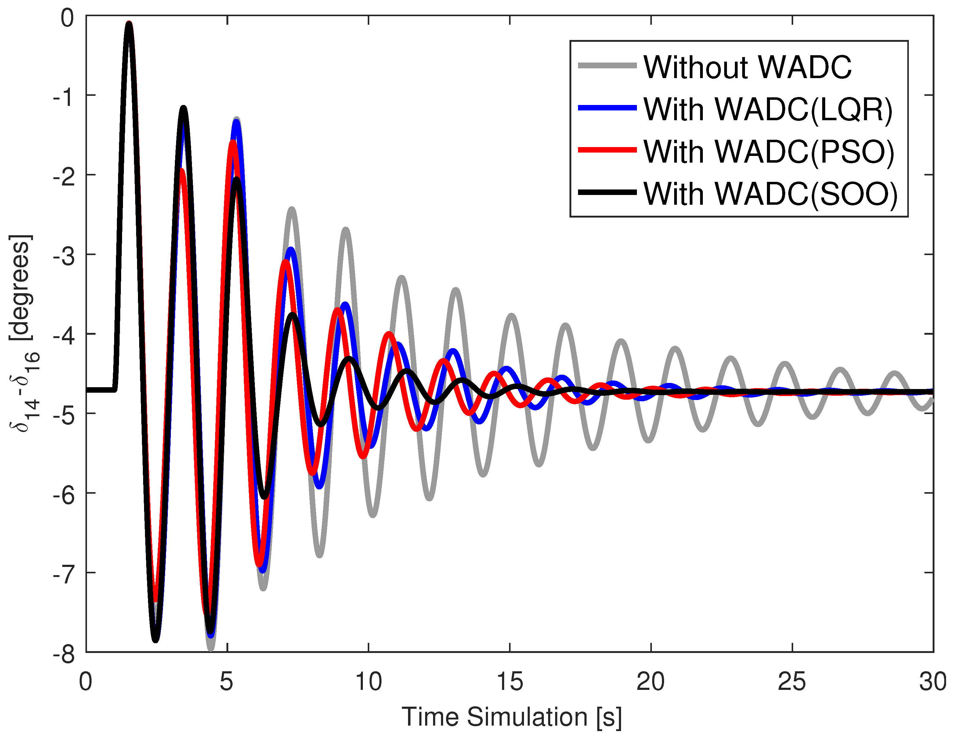
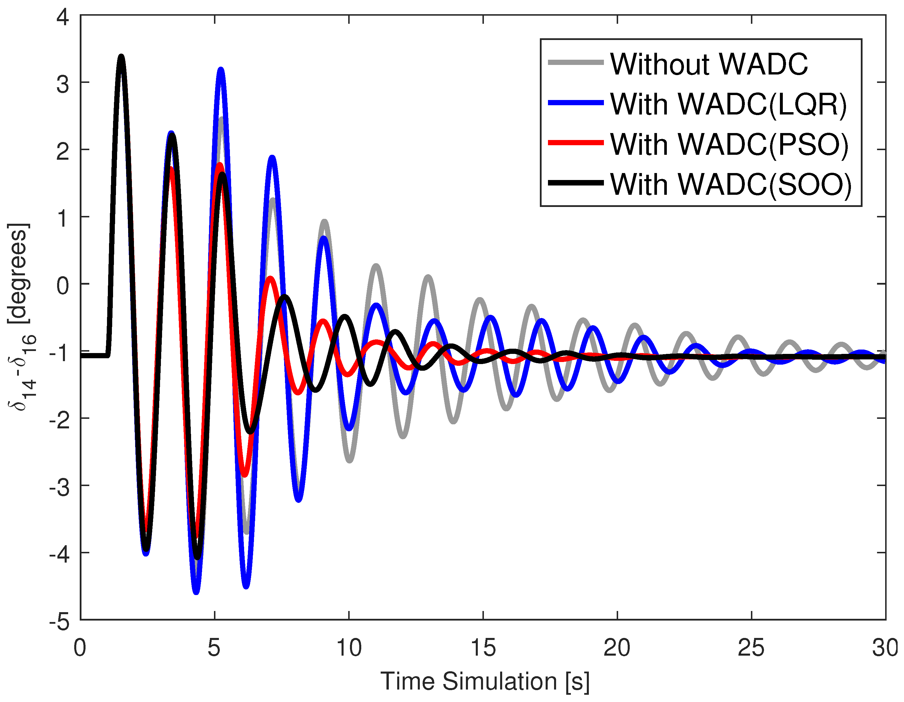
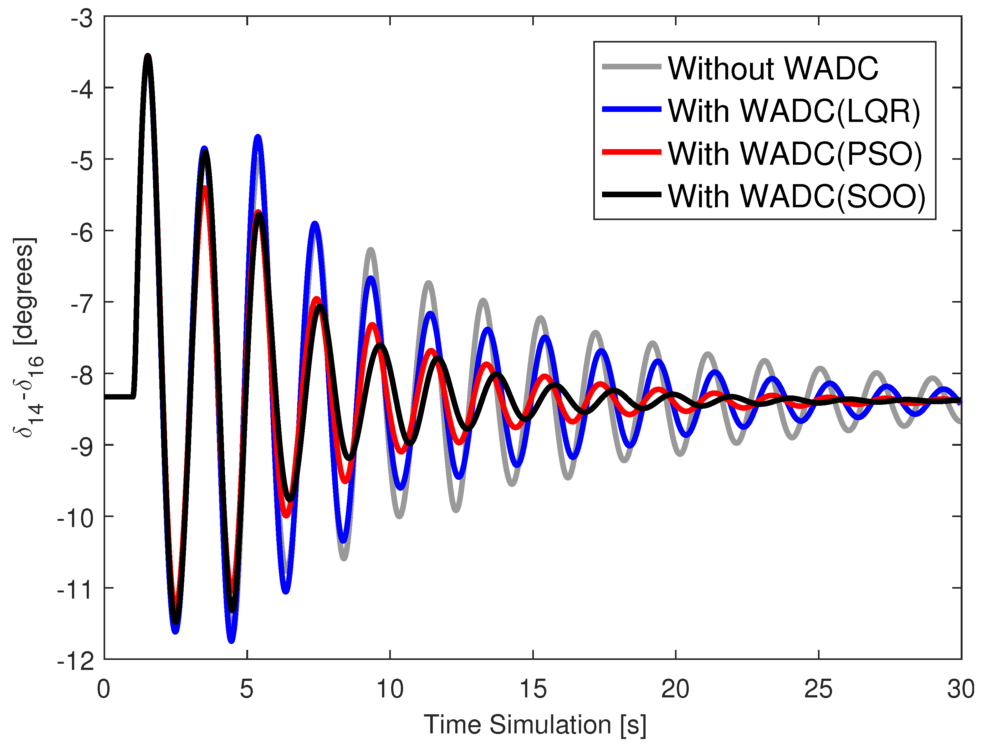
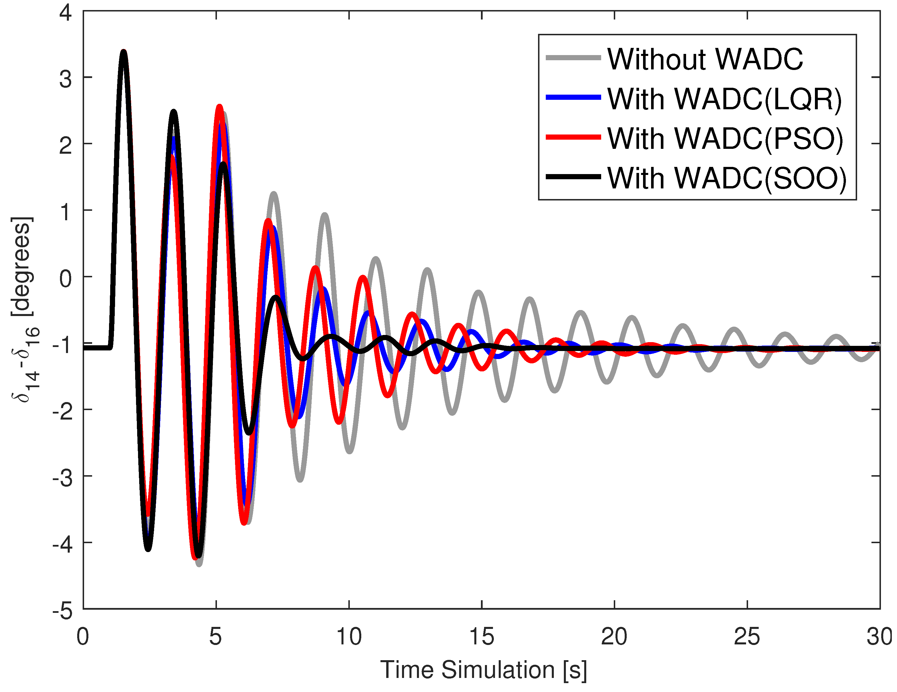
The results presented so far are a modal analysis of the system using linearized models. Therefore, a dynamic analysis of the system subject to contingencies was conducted. System bus 40 was chosen to experience a three-phase fault starting at 1 s and ending 100 ms later for cases C0, C1, C2, and C3, considering the WADCs operating normally and operating with the loss of the speed signal from generator 15, and operating with the loss of the WADC control signal that would go to the AVR of generator 11. Figure 2, Figure 3, Figure 4 and Figure 5 show the angle of generator 14 for cases C0, C1, C2, and C3 for this contingency scenario and with the WADC operating normally. Figure 6, Figure 7, Figure 8 and Figure 9 present the angle of generator 14 for cases C0, C1, C2 and C3 for this contingency scenario and with the WADC operating with the loss of the WADC control signal that would go to the AVR of generator 11. Figure 10, Figure 11, Figure 12 and Figure 13 present the angle of generator 14 for cases C0, C1, C2, and C3 for this contingency scenario and with the WADC operating with the loss of the speed signal from generator 15. These results provide the following observations:
  • The angular responses are well damped for the system operating with a WADC compared to the system without a WADC.
  • Angular responses are well damped for all operating cases, even in the event of a communication failure at the WADC input or output.
  • WADC(SOO) provided slightly better performance than WADC(PSO) in improving the damping of the angular response.
  • The WADC(SOO) provided better damped angular responses than the WADC(LQR) obtained by applying the technique [40].

6. Conclusions

This work proposed an optimization model for the design of a WADC resilient to communication failures. To ensure quadratic stability of the closed-loop control system, the optimization model required finding symmetric and positive-definite matrices that satisfied a set of inequalities. This requirement required that the minimum and maximum bounds of the WADC numerator time constants be between 0 and 0.5 to guarantee convergence. This is important because the SeDuMi solver may have difficulty solving LMIs and finding these symmetric and positive-definite matrices. The SOO and PSO methods were applied and compared to find the WADC parameters in the optimization model. The SOO method achieved a desired minimum value of 3.5965 × 10 8 , while the PSO method achieved a minimum value of 4.5362 × 10 4 . Comparative analyses with the LQR-based technique already existing in the literature showed the difficulty of this existing method in achieving high damping ratios for the oscillation modes, a desirable control objective for the system. Time-domain simulations with contingency and communication channel loss application showed well-damped angular responses with a WADC in the power system, especially for the WADC obtained by the SOO algorithm.
One of the most significant drawbacks of the proposed method is that the symmetric and positive-definite matrices have the same order as those in closed-loop control systems. Therefore, large power systems would have high-dimensional matrices in the linearized model, and thus the variable matrices would have high dimensions. The SeDuMi solver may present convergence problems, hindering the design of a fault-resilient WADC. Another drawback observed during the simulations is the initialization of the variables that define the WADC. In this study, the initialization was random, and different initial values may result in different WADCs with different objective function values.
The successful results of this research have opened new directions for future research, such as the development of WADC design strategies to deal with false data injection attacks. Furthermore, new strategies can be developed to deal with variations in time delays and uncertainties in power system operation. New bio-inspired algorithms can be applied in the future to the proposed multi-objective model, and the results can be compared and analyzed.

Funding

This study was financed in part by the Coordenação de Aperfeiçoamento de Pessoal de Nível Superior-Brasil (CAPES), Finance Code 001, and the Fundação de Amparo à Pesquisa do Estado de São Paulo (FAPESP), under Grant 2015/24245-8.

Data Availability Statement

The original contributions presented in this study are included in the article. Further inquiries can be directed to the corresponding author(s).

Conflicts of Interest

The authors declare that this study received funding from the Coordenação de Aperfeiçoamento de Pessoal de Nível Superior-Brasil (CAPES), Finance Code 001, and the Fundação de Amparo à Pesquisa do Estado de São Paulo (FAPESP), under Grant 2015/24245-8. The funders had no role in the design of the study; in the collection, analyses, or interpretation of data; in the writing of the manuscript; or in the decision to publish the results.

Abbreviations

The following abbreviations are used in this manuscript:
AVRAutomatic Voltage Regulator
LMILinear Matrix Inequality
LQRLinear Quadratic Regulator
PMUPhasor Measurement Unit
PSOParticle Swarm Optimization
PSSPower System Stabilizer
SOOStellar Oscillation Optimizer
WADCWide-Area Damping Controller
WAMSWide-Area Measurement System

References

  1. Bhusal, N.; Abdelmalak, M.; Kamruzzaman, M.; Benidris, M. Power System Resilience: Current Practices, Challenges, and Future Directions. IEEE Access 2020, 8, 18064–18086. [Google Scholar] [CrossRef]
  2. Xiong, L.; Huang, S.; Li, P.; Wang, Z.; Khan, M.W.; Niu, T. Hidden Markov Jump System Based Robust Control of Inverter-Fed Power Systems with Asynchronous Sliding Mode Observer. IEEE Trans. Ind. Electron. 2025, 1–13. [Google Scholar] [CrossRef]
  3. Huang, S.; Wang, L.; Xiong, L.; Zhou, Y.; Gao, F.; Huang, W.; Li, Y.; Guo, H.; Wang, F. Hierarchical Robustness Strategy Combining Model-Free Prediction and Fixed-Time Control for Islanded AC Microgrids. IEEE Trans. Smart Grid 2025, 1. [Google Scholar] [CrossRef]
  4. Liu, C.; Li, B.; Zhang, Y.; Jiang, Q.; Liu, T. The LCC type DC grids forming method and fault ride-through strategy based on fault current limiters. Int. J. Electr. Power Energy Syst. 2025, 170, 110843. [Google Scholar] [CrossRef]
  5. Huang, S.; Xiong, L.; Zhou, Y.; Gao, F.; Jia, Q.; Li, X.; Li, X.; Wang, Z.; Khan, M.W. Distributed Predefined-Time Control for Power System with Time Delay and Input Saturation. IEEE Trans. Power Syst. 2025, 40, 151–165. [Google Scholar] [CrossRef]
  6. Song, R.; Huang, S.; Xiong, L.; Zhou, Y.; Li, T.; Tan, P.; Sun, Z. Takagi–Sugeno Fuzzy Parallel Distributed Compensation Control for Low-Frequency Oscillation Suppression in Wind Energy-Penetrated Power Systems. Electronics 2024, 13, 3795. [Google Scholar] [CrossRef]
  7. Ban, C.; Huang, S.; Xiong, L.; Zhou, Y.; Wang, Q.; Song, R.; Wang, L.; Li, F. Distributed Model Predictive Control Based on Bus Voltage Derivative and SoC Dynamic Model for Shipboard DC Microgrids. Electronics 2024, 13, 2880. [Google Scholar] [CrossRef]
  8. Rogers, G.; Elliott, R.T.; Trudnowski, D.J.; Wilches-Bernal, F.; Osipov, D.; Chow, J.H. Power System Oscillations: An Introduction to Oscillation Analysis and Control; Springer Nature: Cham, Switzerland, 2025. [Google Scholar] [CrossRef]
  9. de Campos, V.A.F.; da Cruz, J.J.; Zanetta, L.C. Robust and optimal adjustment of Power System Stabilizers through Linear Matrix Inequalities. Int. J. Electr. Power Energy Syst. 2012, 42, 478–486. [Google Scholar] [CrossRef]
  10. Abido, M.A. Optimal design of power-system stabilizers using particle swarm optimization. IEEE Trans. Energy Convers. 2002, 17, 406–413. [Google Scholar] [CrossRef]
  11. Bento, M.E.C.; Dotta, D.; Kuiava, R.; Ramos, R.A. Design of Coordinated Decentralized Damping Controllers for Power Systems Considering Uncertainties. J. Control Autom. Electr. Syst. 2018, 29, 22–31. [Google Scholar] [CrossRef]
  12. Abdel-Magid, Y.L.; Abido, M.A. Optimal multiobjective design of robust power system stabilizers using genetic algorithms. IEEE Trans. Power Syst. 2003, 18, 1125–1132. [Google Scholar] [CrossRef]
  13. Sambariya, D.K.; Prasad, R. Robust tuning of power system stabilizer for small signal stability enhancement using metaheuristic bat algorithm. Int. J. Electr. Power Energy Syst. 2014, 61, 229–238. [Google Scholar] [CrossRef]
  14. Peres, W.; de Oliveira, E.J.; Passos Filho, J.A.; da Silva Junior, I.C. Coordinated tuning of power system stabilizers using bio-inspired algorithms. Int. J. Electr. Power Energy Syst. 2015, 64, 419–428. [Google Scholar] [CrossRef]
  15. Hattabi, I.; Kheldoun, A.; Bradai, R.; Khettab, S.; Sabo, A.; Belkhier, Y.; Khosravi, N.; Oubelaid, A. Enhanced power system stabilizer tuning using marine predator algorithm with comparative analysis and real time validation. Sci. Rep. 2024, 14, 28971. [Google Scholar] [CrossRef] [PubMed]
  16. Pazderin, A.; Zicmane, I.; Senyuk, M.; Gubin, P.; Polyakov, I.; Mukhlynin, N.; Safaraliev, M.; Kamalov, F. Directions of Application of Phasor Measurement Units for Control and Monitoring of Modern Power Systems: A State-of-the-Art Review. Energies 2023, 16, 6203. [Google Scholar] [CrossRef]
  17. Zhang, Y.; Bose, A. Design of Wide-Area Damping Controllers for Interarea Oscillations. IEEE Trans. Power Syst. 2008, 23, 1136–1143. [Google Scholar] [CrossRef]
  18. Li, F.; Qiao, W.; Sun, H.; Wan, H.; Wang, J.; Xia, Y.; Xu, Z.; Zhang, P. Smart Transmission Grid: Vision and Framework. IEEE Trans. Smart Grid 2010, 1, 168–177. [Google Scholar] [CrossRef]
  19. Sodhi, R.; Srivastava, S.C.; Singh, S.N. Optimal PMU placement method for complete topological and numerical observability of power system. Electr. Power Syst. Res. 2010, 80, 1154–1159. [Google Scholar] [CrossRef]
  20. Zhang, X.; Lu, C.; Liu, S.; Wang, X. A review on wide-area damping control to restrain inter-area low frequency oscillation for large-scale power systems with increasing renewable generation. Renew. Sustain. Energy Rev. 2016, 57, 45–58. [Google Scholar] [CrossRef]
  21. Yu, M.; Sun, J.; Tian, S.; Wu, Y.; Wei, J.; Wu, H. An Improved Smith Predictor for Wide-Area Damping Control Considering Time-Delays in Power System. IEEE Access 2024, 12, 107394–107405. [Google Scholar] [CrossRef]
  22. Bento, M.E.C. Wide-Area Measurement-Based Two-Level Control Design to Tolerate Permanent Communication Failures. Energies 2023, 16, 5646. [Google Scholar] [CrossRef]
  23. Mukherjee, S.; Chakrabortty, A.; Bai, H.; Darvishi, A.; Fardanesh, B. Scalable Designs for Reinforcement Learning-Based Wide-Area Damping Control. IEEE Trans. Smart Grid 2021, 12, 2389–2401. [Google Scholar] [CrossRef]
  24. Gupta, P.; Pal, A.; Vittal, V. Coordinated Wide-Area Damping Control Using Deep Neural Networks and Reinforcement Learning. IEEE Trans. Power Syst. 2022, 37, 365–376. [Google Scholar] [CrossRef]
  25. Ranjbar, S.; Aghamohammadi, M.; Haghjoo, F. A new scheme of WADC for damping inter-area oscillation based on CART technique and Thevenine impedance. Int. J. Electr. Power Energy Syst. 2018, 94, 339–353. [Google Scholar] [CrossRef]
  26. Bento, M.E.C. An Optimization Approach for the Wide-Area Damping Control Design. In Proceedings of the 2018 13th IEEE International Conference on Industry Applications (INDUSCON), Sao Paulo, Brazil, 12–14 November 2018; IEEE: New York, NY, USA, 2018; pp. 269–276. [Google Scholar] [CrossRef]
  27. Peres, W. An Unscented Transformation based approach for probabilistic design of Wide-Area Damping Controllers. Sustain. Comput. Inform. Syst. 2025, 46, 101116. [Google Scholar] [CrossRef]
  28. Bento, M.E.C. Design of a Decentralized Wide-Area Damping Controller Resilient to Permanent Communication Failures. IEEE Trans. Ind. Appl. 2025, 61, 4936–4947. [Google Scholar] [CrossRef]
  29. Surinkaew, T.; Ngamroo, I. Hierarchical Co-Ordinated Wide Area and Local Controls of DFIG Wind Turbine and PSS for Robust Power Oscillation Damping. IEEE Trans. Sustain. Energy 2016, 7, 943–955. [Google Scholar] [CrossRef]
  30. Yuan, Y.; Sun, Y.; Cheng, L. Design of Delayed-Input Wide-area FACTS Controller Using Genetic Algorithm. In Proceedings of the 2007 IEEE Power Engineering Society General Meeting, Tampa, FL, USA, 24–28 June 2007; pp. 1–6. [Google Scholar] [CrossRef]
  31. Bento, M.E.C. Design analysis of wide-area damping controllers using genetic algorithms. In Proceedings of the 2016 12th IEEE International Conference on Industry Applications (INDUSCON), Curitiba, Brazil, 20–23 November 2016; IEEE: New York, NY, USA, 2016; pp. 1–8. [Google Scholar] [CrossRef]
  32. Bento, M.E.C. Design of a Wide-Area Power System Stabilizer to Tolerate Multiple Permanent Communication Failures. Electricity 2023, 4, 154–170. [Google Scholar] [CrossRef]
  33. Bento, M.E.C. Design of a Wide-Area Power System Stabilizer resilient to permanent communication failures using bio-inspired algorithms. Results Control Optim. 2023, 12, 100258. [Google Scholar] [CrossRef]
  34. Bento, M.E.C. Design of a Resilient Wide-Area Damping Controller Using African Vultures Optimization Algorithm. In Proceedings of the 2021 31st Australasian Universities Power Engineering Conference (AUPEC), Perth, Australia, 26–30 September 2021; IEEE: New York, NY, USA, 2021; pp. 1–6. [Google Scholar] [CrossRef]
  35. Bento, M.E.C. Design of a resilient wide-area damping controller using time delays. Electr. Eng. 2025, 107, 1111–1124. [Google Scholar] [CrossRef]
  36. Bento, M.E.C. Resilient Wide-Area Damping Controller Design Using Crow Search Algorithm. IFAC-PapersOnLine 2022, 55, 938–943. [Google Scholar] [CrossRef]
  37. Zhang, S.; Vittal, V. Design of Wide-Area Power System Damping Controllers Resilient to Communication Failures. IEEE Trans. Power Syst. 2013, 28, 4292–4300. [Google Scholar] [CrossRef]
  38. Naguru, N.R. Detection and Correction Matrix-Based Wide Area Damping Controller Design to Tolerate All Kinds of Communication Failures. IEEE Access 2024, 12, 91909–91927. [Google Scholar] [CrossRef]
  39. Sarkar, M.; Subudhi, B.; Ghosh, S. Unified Smith predictor based H wide-area damping controller to improve the control resiliency to communication failure. IEEE/CAA J. Autom. Sin. 2020, 7, 584–596. [Google Scholar] [CrossRef]
  40. Bento, M.E.C. Fixed Low-Order Wide-Area Damping Controller Considering Time Delays and Power System Operation Uncertainties. IEEE Trans. Power Syst. 2020, 35, 3918–3926. [Google Scholar] [CrossRef]
  41. Yao, W.; Nan, J.; Zhao, Y.; Fang, J.; Ai, X.; Zuo, W.; Wen, J.; Cheng, S. Resilient Wide-Area Damping Control for Inter-Area Oscillations to Tolerate Deception Attacks. IEEE Trans. Smart Grid 2021, 12, 4238–4249. [Google Scholar] [CrossRef]
  42. Patel, A.; Roy, S.; Baldi, S. Wide-Area Damping Control Resilience Towards Cyber-Attacks: A Dynamic Loop Approach. IEEE Trans. Smart Grid 2021, 12, 3438–3447. [Google Scholar] [CrossRef]
  43. Zhang, S.; Vittal, V. Wide-Area Control Resiliency Using Redundant Communication Paths. IEEE Trans. Power Syst. 2014, 29, 2189–2199. [Google Scholar] [CrossRef]
  44. Liu, S.; Zenelis, I.; Li, Y.; Wang, X.; Li, Q.; Zhu, L. Markov Game for Securing Wide-Area Damping Control Against False Data Injection Attacks. IEEE Syst. J. 2021, 15, 1356–1365. [Google Scholar] [CrossRef]
  45. Zhao, Y.; Yao, W.; Nan, J.; Fang, J.; Ai, X.; Wen, J.; Cheng, S. Resilient Adaptive Wide-Area Damping Control to Mitigate False Data Injection Attacks. IEEE Syst. J. 2021, 15, 4831–4842. [Google Scholar] [CrossRef]
  46. Sun, Z.; Long, H.; Li, Z.; Gao, B.; Wei, X.; Levron, Y.; Belikov, J. Wide-Area damping control enhanced by non-invasive data verification against false data injection attacks. Electr. Power Syst. Res. 2025, 242, 111448. [Google Scholar] [CrossRef]
  47. Vavdareh, M.B.; Ghafouri, M.; Ameli, A. Developing Multi-Agent Wide Area Damping Controller to Mitigate False Data Injection Attacks. In Proceedings of the 2024 IEEE International Conference on Environment and Electrical Engineering and 2024 IEEE Industrial and Commercial Power Systems Europe (EEEIC/I&CPS Europe), Rome, Italy, 17–20 June 2024; pp. 1–6. [Google Scholar] [CrossRef]
  48. Kumar, K.; Saini, P.; Prakash, A.; Parida, S.K.; Al Jaafari, K. Detection and Mitigation of False Data Injection Attacks in Wide-Area Damping Controller Using Random Forest Classifier. In Proceedings of the 2024 23rd National Power Systems Conference (NPSC), Indore, India, 14–16 December 2024; pp. 1–6. [Google Scholar] [CrossRef]
  49. Saini, A.; Bhui, P. Securing Wide-Area Damping Controller Against Cyber Attacks using Semi-Supervised Generative Adversarial Network and Support Vector Machine-Based Synthetic Minority Oversampling Technique. J. Mod. Power Syst. Clean Energy 2025, 1–13. [Google Scholar] [CrossRef]
  50. Saini, A.; Mustafa, H.M.; Bhui, P.; Srivastava, A.K. Non-intrusive Hybrid Two-stage Detection of Dynamic Attacks in Wide-area Damping Controller Using Autoencoder and Unscented Kalman Filter with Unknown Input Estimation. J. Mod. Power Syst. Clean Energy 2025, 13, 1763–1775. [Google Scholar] [CrossRef]
  51. Zhao, Y.; Yao, W.; Zhang, C.K.; Ai, X.; Wen, J. Resilient Wide-Area Damping Control to Mitigate Strong Cyber Attack: A Multiple-Controller Switching Approach. IEEE Trans. Smart Grid 2023, 14, 2326–2337. [Google Scholar] [CrossRef]
  52. Li, Q.; Li, Y.; Liu, S.; Wang, X.; Chaoui, H. Incomplete Information Stochastic Game Theoretic Vulnerability Management for Wide-Area Damping Control Against Cyber Attacks. IEEE J. Emerg. Sel. Top. Circuits Syst. 2022, 12, 124–134. [Google Scholar] [CrossRef]
  53. Zhao, Y.; Yao, W.; Wen, J. Resilient Wide-Area Damping Control to Mitigate Sparse Attack Using Robust Subspace Tracking. In Proceedings of the 2023 IEEE 7th Conference on Energy Internet and Energy System Integration (EI2), Hangzhou, China, 15–18 December 2023; pp. 2680–2685. [Google Scholar] [CrossRef]
  54. Zhao, Y.; Yao, W.; Zhang, C.K.; Shangguan, X.C.; Jiang, L.; Wen, J. Quantifying Resilience of Wide-Area Damping Control Against Cyber Attack Based on Switching System Theory. IEEE Trans. Smart Grid 2022, 13, 2331–2343. [Google Scholar] [CrossRef]
  55. Bento, M.E.C.; Dotta, D.; Ramos, R.A. Performance analysis of Wide-Area Damping Control Design methods. In Proceedings of the 2016 IEEE Power and Energy Society General Meeting (PESGM), Boston, MA, USA, 17–21 July 2016; IEEE: New York, NY, USA, 2016. [Google Scholar] [CrossRef]
  56. de Campos, V.A.F.; da Cruz, J.J. Robust hierarchized controllers using wide area measurements in power systems. Int. J. Electr. Power Energy Syst. 2016, 83, 392–401. [Google Scholar] [CrossRef]
  57. Rodan, A.; Al-Tamimi, A.K.; Al-Alnemer, L.; Mirjalili, S. Stellar oscillation optimizer: A nature-inspired metaheuristic optimization algorithm. Clust. Comput. 2025, 28, 362. [Google Scholar] [CrossRef]
  58. Kennedy, J.; Eberhart, R. Particle swarm optimization. In Proceedings of the ICNN’95-International Conference on Neural Networks, Perth, Australia, 27 November–1 December 1995; Volume 4, pp. 1942–1948. [Google Scholar] [CrossRef]
  59. Canizares, C.; Fernandes, T.; Geraldi, E.; Gerin-Lajoie, L.; Gibbard, M.; Hiskens, I.; Kersulis, J.; Kuiava, R.; Lima, L.; DeMarco, F.; et al. Benchmark Systems for Small-Signal Stability Analysis and Control. In Power & Energy Society Technical Report PES-TR18; IEEE: New York, NY, USA, 2015; pp. 1–390. Available online: https://resourcecenter.ieee-pes.org/publications/technical-reports/pestr18 (accessed on 1 August 2025).
  60. Liu, S.; Liu, X.P.; El Saddik, A. Denial-of-Service (dos) attacks on load frequency control in smart grids. In Proceedings of the 2013 IEEE PES Innovative Smart Grid Technologies Conference (ISGT), Washington, DC, USA, 24–27 February 2013; IEEE: New York, NY, USA, 2013; pp. 1–6. [Google Scholar] [CrossRef]
  61. Boyd, S.; El Ghaoui, L.; Feron, E.; Balakrishnan, V. Linear Matrix Inequalities in System and Control Theory; Society for Industrial and Applied Mathematics: Philadelphia, PA, USA, 1994. [Google Scholar] [CrossRef]
  62. Sturm, J.F. Using SeDuMi 1.02, A Matlab toolbox for optimization over symmetric cones. Optim. Methods Softw. 1999, 11, 625–653. [Google Scholar] [CrossRef]
  63. Lofberg, J. YALMIP: A toolbox for modeling and optimization in MATLAB. In Proceedings of the 2004 IEEE International Conference on Robotics and Automation (IEEE Cat. No.04CH37508), Taipei, Taiwan, 2–4 September 2004; IEEE: New York, NY, USA, 2004. CACSD-04. pp. 284–289. [Google Scholar] [CrossRef]
  64. Liu, F.; Gao, C.; Liu, L. SK-PSO: A Particle Swarm Optimization Framework with SOM and K-Means for Inverse Kinematics of Manipulators. Symmetry 2024, 16, 1667. [Google Scholar] [CrossRef]
  65. Canizares, C.; Fernandes, T.; Geraldi, E.; Gerin-Lajoie, L.; Gibbard, M.; Hiskens, I.; Kersulis, J.; Kuiava, R.; Lima, L.; DeMarco, F.; et al. Benchmark Models for the Analysis and Control of Small-Signal Oscillatory Dynamics in Power Systems. IEEE Trans. Power Syst. 2017, 32, 715–722. [Google Scholar] [CrossRef]
  66. MATLAB. Mathworks Inc. 2016. Available online: https://www.mathworks.com/products/matlab.html (accessed on 1 August 2025).
  67. CEPEL. ANATEM User’s Manual. 2024. Available online: https://see.cepel.br/manual/anatem/ (accessed on 1 August 2025).
Figure 1. Proposed control structure composed of two levels.
Symmetry 17 01781 g001
Figure 2. Generator angle 14 after applying the contingency to the operating point C0.
Symmetry 17 01781 g002
Figure 3. Generator angle 14 after applying the contingency to the operating point C1.
Symmetry 17 01781 g003
Figure 4. Generator angle 14 after applying the contingency to the operating point C2.
Symmetry 17 01781 g004
Figure 5. Generator angle 14 after applying the contingency to the operating point C3.
Symmetry 17 01781 g005
Figure 6. Generator angle 14 after applying the contingency to the operating point C0 and loss of the control signal that would go to the generator AVR 11.
Symmetry 17 01781 g006
Figure 7. Generator angle 14 after applying the contingency to the operating point C1 and loss of the control signal that would go to the generator AVR 11.
Symmetry 17 01781 g007
Figure 8. Generator angle 14 after applying the contingency to the operating point C2 and loss of the control signal that would go to the generator AVR 11.
Symmetry 17 01781 g008
Figure 9. Generator angle 14 after applying the contingency to the operating point C3 and loss of the control signal that would go to the generator AVR 11.
Symmetry 17 01781 g009
Figure 10. Generator angle 14 after applying the contingency to the operating point C0 and loss of generator speed signal 15.
Symmetry 17 01781 g010
Figure 11. Generator angle 14 after applying the contingency to the operating point C1 and loss of generator speed signal 15.
Symmetry 17 01781 g011
Figure 12. Generator angle 14 after applying the contingency to the operating point C2 and loss of generator speed signal 15.
Symmetry 17 01781 g012
Figure 13. Generator angle 14 after applying the contingency to the operating point C3 and loss of generator speed signal 15.
Symmetry 17 01781 g013
Table 1. Oscillation modes.
CaseModes (Eigenvalues)Frequency (Hz)Damping Ratio (%)
C0 0.1656 ± j 4.8917 0.77853.3850
0.1184 ± j 3.2664 0.51983.6236
C1 0.1058 ± j 3.2382 0.51533.2675
0.1650 ± j 4.8894 0.77813.3730
C2 0.0926 ± j 3.2036 0.50982.8918
0.1643 ± j 4.8854 0.77753.3615
C3 0.0796 ± j 3.1613 0.50312.5188
0.1635 ± j 4.8796 0.77663.3501
Table 2. Multi-objective function results for 100 simulations for the SOO and PSO algorithms.
MethodMinimumAverageMaximumStandard Deviation
SOO 3.5965 × 10 8 2.6455 × 10 7 5.6893 × 10 7 1.4390 × 10 7
PSO 4.5362 × 10 4 7.7299 × 10 3 1.4461 × 10 2 4.2134 × 10 3
Table 3. WADC parameters of the SOO method (WADC(SOO)).
h k , m K k , m T 1 k , m T 2 k , m T 3 k , m T 4 k , m T 5 k , m
h 5 , 12 10.53990.43190.03630.01080.01230.0126
h 5 , 13 −4.54740.15060.48000.01080.01230.0126
h 5 , 14 23.28270.32560.10230.01080.01230.0126
h 5 , 15 27.23650.47580.48740.01080.01230.0126
h 5 , 16 −27.24990.49670.12460.01080.01230.0126
h 9 , 12 10.78410.14360.04330.01080.01230.0126
h 9 , 13 9.06720.11460.20870.01080.01230.0126
h 9 , 14 29.81700.45410.34210.01080.01230.0126
h 9 , 15 27.36850.44700.06110.01080.01230.0126
h 9 , 16 0.99070.31840.34690.01080.01230.0126
h 10 , 12 27.24510.06460.08590.01080.01230.0126
h 10 , 13 12.35110.35780.31960.01080.01230.0126
h 10 , 14 29.32610.27820.48790.01080.01230.0126
h 10 , 15 −28.75320.48990.48540.01080.01230.0126
h 10 , 16 28.12570.40830.40290.01080.01230.0126
h 11 , 12 6.08160.19820.21830.01080.01230.0126
h 11 , 13 9.39290.49390.49740.01080.01230.0126
h 11 , 14 15.17710.26080.26960.01080.01230.0126
h 11 , 15 −21.26250.48120.11180.01080.01230.0126
h 11 , 16 29.81480.49410.49570.01080.01230.0126
h 12 , 12 −28.11790.28230.02820.01080.01230.0126
h 12 , 13 2.63790.35600.43920.01080.01230.0126
h 12 , 14 29.78730.05770.28750.01080.01230.0126
h 12 , 15 26.35270.01300.03660.01080.01230.0126
h 12 , 16 −18.36920.06380.21400.01080.01230.0126
Table 4. WADC parameters of the PSO method (WADC(PSO)).
h k , m K k , m T 1 k , m T 2 k , m T 3 k , m T 4 k , m T 5 k , m
h 5 , 12 22.12390.00120.27550.06460.02280.0181
h 5 , 13 −15.68650.07480.03300.06460.02280.0181
h 5 , 14 20.09920.33940.16810.06460.02280.0181
h 5 , 15 16.10680.40520.49660.06460.02280.0181
h 5 , 16 17.55830.00390.05160.06460.02280.0181
h 9 , 12 −0.00380.42770.04990.06460.02280.0181
h 9 , 13 −0.99530.23580.01680.06460.02280.0181
h 9 , 14 3.22100.35810.47080.06460.02280.0181
h 9 , 15 29.59090.49990.08790.06460.02280.0181
h 9 , 16 2.14830.42600.37320.06460.02280.0181
h 10 , 12 7.85340.36640.44580.06460.02280.0181
h 10 , 13 29.90170.16860.47720.06460.02280.0181
h 10 , 14 −29.54070.46050.00300.06460.02280.0181
h 10 , 15 22.70180.02730.33490.06460.02280.0181
h 10 , 16 18.90400.41600.49920.06460.02280.0181
h 11 , 12 17.47490.41680.47230.06460.02280.0181
h 11 , 13 −18.69270.19090.46200.06460.02280.0181
h 11 , 14 −0.55350.10520.17050.06460.02280.0181
h 11 , 15 27.27290.14440.02840.06460.02280.0181
h 11 , 16 20.15480.47010.48600.06460.02280.0181
h 12 , 12 −10.37730.46320.01630.06460.02280.0181
h 12 , 13 0.42290.32500.06130.06460.02280.0181
h 12 , 14 21.23240.00090.49900.06460.02280.0181
h 12 , 15 19.75650.07660.36730.06460.02280.0181
h 12 , 16 −27.50900.40960.11190.06460.02280.0181
Table 5. WADC parameters of the LQR method (WADC(LQR)).
h k , m num(s)
h 5 , 12 10.382 s 2 889.54 s 6554.2
h 5 , 13 1061.2 s 2 + 4102.6 s + 3823.1
h 5 , 14 7.4885 s 2 1236.2 s 1669.8
h 5 , 15 222.51 s 2 + 743 s + 597.26
h 5 , 16 98.348 s 2 + 1989.7 s + 8569.5
h 9 , 12 537.28 s 2 + 6447 s + 15017
h 9 , 13 1782.2 s 2 11014 s 17002
h 9 , 14 819.5 s 2 + 7058.5 s + 6481
h 9 , 15 1925.6 s 2 + 15244 s + 20860
h 9 , 16 1319.1 s 2 + 7116 s + 9012.1
h 10 , 12 4328.1 s 2 + 14361 s + 11901
h 10 , 13 2691.3 s 2 + 13036 s + 13854
h 10 , 14 3210.7 s 2 + 11832 s + 10893
h 10 , 15 4121.7 s 2 13085 s 10217
h 10 , 16 3699.9 s 2 + 18664 s + 23498
h 11 , 12 68.9 s 2 + 1508.8 s + 4029.7
h 11 , 13 4014.6 s 2 + 14897 s + 13764
h 11 , 14 299.9 s 2 + 5997.9 s + 11041
h 11 , 15 2169.5 s 2 + 10222 s + 10028
h 11 , 16 5592.3 s 2 + 12079 s + 6489.3
h 12 , 12 163.39 s 2 4551.3 s 5291.6
h 12 , 13 533.73 s 2 3122.6 s 3510.6
h 12 , 14 1694.3 s 2 + 7277.6 s + 7531.7
h 12 , 15 1233.8 s 2 + 4946.5 s + 4957.4
h 12 , 16 559.65 s 2 + 2058.8 s + 1885.6
Table 6. Oscillation modes for C0 case with WADC(SOO).
Signal LossModes (Eigenvalues)Frequency (Hz)Damping Ratio (%)
None 0.5057 ± j 5.5996 0.89128.9953
0.4360 ± j 3.8897 0.619111.1391
0.5663 ± j 4.8950 0.779111.4933
V C 5 0.2542 ± j 3.1916 0.50807.9395
0.5156 ± j 5.0322 0.800910.1922
0.4418 ± j 4.0174 0.639410.9322
V C 9 0.2592 ± j 3.5220 0.56057.3388
0.4016 ± j 4.9777 0.79228.0416
1.0707 ± j 8.0447 1.280413.1932
V C 10 0.3850 ± j 4.9503 0.78797.7540
0.4517 ± j 3.8232 0.608511.7342
1.1029 ± j 8.0848 1.286713.5168
V C 11 0.3468 ± j 4.9857 0.79356.9384
0.3411 ± j 3.8578 0.61408.8079
0.2950 ± j 2.9915 0.47619.8152
V C 12 0.3205 ± j 3.9833 0.63408.0208
0.2587 ± j 3.1837 0.50678.0978
0.5114 ± j 5.0981 0.81149.9817
Δ ω 12 0.3928 ± j 3.2668 0.519911.9386
0.5029 ± j 4.1113 0.654312.1407
0.7546 ± j 5.6529 0.899713.2311
Δ ω 13 0.2079 ± j 3.7066 0.58995.6000
0.3544 ± j 5.0508 0.80396.9995
0.3437 ± j 2.8622 0.455511.9215
Δ ω 14 0.2184 ± j 3.4901 0.55556.2441
0.3409 ± j 4.8615 0.77376.9960
1.0699 ± j 8.0549 1.282013.1669
Δ ω 15 0.3602 ± j 5.0810 0.80877.0705
0.3664 ± j 3.9030 0.62129.3466
0.3082 ± j 3.1220 0.49699.8231
Δ ω 16 0.2215 ± j 3.0982 0.49317.1299
0.4799 ± j 5.0002 0.79589.5542
0.4699 ± j 4.0211 0.640011.6075
Table 7. Oscillation modes for C1 case with WADC(SOO).
Signal LossModes (Eigenvalues)Frequency (Hz)Damping Ratio (%)
None 0.4919 ± j 5.6032 0.89188.7453
0.3473 ± j 3.1745 0.505210.8747
0.5905 ± j 4.8835 0.777212.0035
V C 5 0.2374 ± j 3.1753 0.50547.4555
0.5996 ± j 5.5611 0.885110.7207
0.5447 ± j 5.0309 0.800710.7649
V C 9 0.2575 ± j 3.4137 0.54337.5216
0.4217 ± j 4.9768 0.79218.4421
1.0707 ± j 8.0442 1.280313.1944
V C 10 0.4022 ± j 4.9501 0.78788.0989
0.3927 ± j 3.1910 0.507912.2158
0.5054 ± j 3.8196 0.607913.1164
V C 11 0.3533 ± j 4.9921 0.79457.0604
0.2603 ± j 3.0334 0.48288.5502
0.3620 ± j 3.8331 0.61019.4026
V C 12 0.2280 ± j 3.1865 0.50727.1365
0.3391 ± j 3.9888 0.63488.4699
0.5302 ± j 5.1096 0.813210.3204
Δ ω 12 0.3258 ± j 3.2266 0.513510.0460
0.5162 ± j 4.1298 0.657312.4027
0.7343 ± j 5.6441 0.898312.9013
Δ ω 13 0.2324 ± j 3.6702 0.58416.3181
0.3625 ± j 5.0611 0.80557.1449
0.3331 ± j 2.9481 0.469211.2273
Δ ω 14 0.2143 ± j 3.3919 0.53986.3063
0.3528 ± j 4.8497 0.77187.2548
1.0699 ± j 8.0544 1.281913.1679
Δ ω 15 0.3739 ± j 5.0855 0.80947.3316
0.2795 ± j 3.1257 0.49758.9064
0.4013 ± j 3.8763 0.616910.2987
Δ ω 16 0.2028 ± j 3.1101 0.49506.5076
0.4989 ± j 5.0140 0.79809.9011
0.4768 ± j 4.0033 0.637111.8261
Table 8. Oscillation modes for C2 case with WADC(SOO).
Signal LossModes (Eigenvalues)Frequency (Hz)Damping Ratio (%)
None 0.4813 ± j 5.6063 0.89238.5528
0.2860 ± j 3.1649 0.50378.9998
0.6119 ± j 4.8708 0.775212.4649
V C 5 0.2162 ± j 3.1522 0.50176.8425
0.5822 ± j 5.5611 0.885110.4125
0.5708 ± j 5.0253 0.799811.2857
V C 9 0.2207 ± j 3.3034 0.52586.6658
0.4403 ± j 4.9721 0.79138.8202
1.0706 ± j 8.0436 1.280213.1932
V C 10 0.4182 ± j 4.9466 0.78738.4248
0.3120 ± j 3.1749 0.50539.7795
0.7232 ± j 5.3853 0.857113.3097
V C 11 0.2196 ± j 3.0648 0.48787.1476
0.3587 ± j 4.9963 0.79527.1612
0.3892 ± j 3.8081 0.606110.1678
V C 12 0.1967 ± j 3.1801 0.50616.1731
0.3581 ± j 3.9956 0.63598.9267
0.5469 ± j 5.1182 0.814610.6246
Δ ω 12 0.2567 ± j 3.1900 0.50778.0200
0.5276 ± j 4.1481 0.660212.6178
0.7188 ± j 5.6388 0.897412.6449
Δ ω 13 0.3695 ± j 5.0690 0.80687.2697
0.2690 ± j 3.6289 0.57767.3921
0.2967 ± j 3.0174 0.48029.7865
Δ ω 14 0.1910 ± j 3.3020 0.52555.7743
0.3630 ± j 4.8350 0.76957.4876
1.0697 ± j 8.0538 1.281813.1663
Δ ω 15 0.3865 ± j 5.0854 0.80947.5788
0.2431 ± j 3.1230 0.49707.7616
0.4430 ± j 3.8513 0.613011.4276
Δ ω 16 0.1810 ± j 3.1164 0.49605.7972
0.5152 ± j 5.0261 0.799910.1974
0.4868 ± j 3.9841 0.634112.1279
Table 9. Oscillation modes for C3 case with WADC(SOO).
Signal LossModes (Eigenvalues)Frequency (Hz)Damping Ratio (%)
None 0.2255 ± j 3.1432 0.50037.1563
0.4739 ± j 5.6083 0.89268.4206
0.6306 ± j 4.8571 0.773012.8741
V C 5 0.1910 ± j 3.1214 0.49686.1070
0.5689 ± j 5.5627 0.885310.1732
0.5927 ± j 5.0161 0.798311.7339
V C 9 0.1673 ± j 3.2054 0.51025.2131
0.4565 ± j 4.9636 0.79009.1577
1.0702 ± j 8.0431 1.280113.1894
V C 10 0.2370 ± j 3.1468 0.50087.5087
0.4321 ± j 4.9394 0.78618.7150
0.7094 ± j 5.3850 0.857013.0601
V C 11 0.1726 ± j 3.0832 0.49075.5904
0.3627 ± j 4.9977 0.79547.2387
0.4224 ± j 3.7860 0.602611.0886
V C 12 0.1654 ± j 3.1636 0.50355.2216
0.3770 ± j 4.0040 0.63729.3744
0.5610 ± j 5.1230 0.815310.8849
Δ ω 12 0.1912 ± j 3.1547 0.50216.0510
0.7103 ± j 5.6353 0.896912.5063
0.5372 ± j 4.1657 0.663012.7908
Δ ω 13 0.3750 ± j 5.0738 0.80757.3717
0.2359 ± j 3.0679 0.48837.6672
0.3251 ± j 3.5899 0.57139.0184
Δ ω 14 0.1614 ± j 3.2170 0.51205.0111
0.3713 ± j 4.8177 0.76687.6839
1.0692 ± j 8.0531 1.281713.1617
Δ ω 15 0.2004 ± j 3.1103 0.49506.4292
0.3973 ± j 5.0797 0.80857.7980
0.6512 ± j 5.4327 0.864611.9015
Δ ω 16 0.1559 ± j 3.1154 0.49584.9982
0.5278 ± j 5.0354 0.801410.4242
0.6723 ± j 5.3575 0.852712.4504
Table 10. Oscillation modes for C0 case with WADC(PSO).
Signal LossModes (Eigenvalues)Frequency (Hz)Damping Ratio (%)
None 0.2560 ± j 4.8914 0.77855.2266
0.2485 ± j 3.4820 0.55427.1181
0.2541 ± j 2.2817 0.363111.0666
V C 5 0.2401 ± j 4.8912 0.77854.9037
0.1993 ± j 3.4606 0.55085.7488
1.0774 ± j 8.0584 1.282513.2519
V C 9 0.2186 ± j 4.9196 0.78304.4398
0.2854 ± j 3.3913 0.53978.3849
0.3410 ± j 3.6907 0.58749.1992
V C 10 0.2170 ± j 4.8992 0.77974.4253
0.2142 ± j 3.5279 0.56156.0613
0.2160 ± j 2.3393 0.37239.1945
V C 11 0.2459 ± j 4.8354 0.76965.0787
0.2990 ± j 3.1890 0.50759.3336
0.3748 ± j 3.7489 0.59679.9481
V C 12 0.1401 ± j 3.4038 0.54174.1139
0.2572 ± j 4.8680 0.77485.2751
0.7302 ± j 7.3321 1.16699.9098
Δ ω 12 0.2445 ± j 4.8680 0.77485.0162
0.2280 ± j 3.5381 0.56316.4294
0.2128 ± j 2.4124 0.38408.7859
Δ ω 13 0.2621 ± j 4.8897 0.77825.3524
0.2276 ± j 3.4572 0.55026.5697
0.2646 ± j 2.2703 0.361311.5757
Δ ω 14 0.2388 ± j 4.9172 0.78264.8511
0.1976 ± j 3.4197 0.54435.7688
1.0781 ± j 8.0537 1.281813.2680
Δ ω 15 0.1911 ± j 4.9095 0.78143.8897
0.2811 ± j 3.7086 0.59027.5589
0.2919 ± j 3.3179 0.52818.7650
Δ ω 16 0.2442 ± j 4.8468 0.77145.0311
0.2199 ± j 3.2998 0.52526.6485
0.2371 ± j 2.1440 0.341210.9899
Table 11. Oscillation modes for C1 case with WADC(PSO).
Signal LossModes (Eigenvalues)Frequency (Hz)Damping Ratio (%)
None 0.2628 ± j 4.8877 0.77795.3685
0.2545 ± j 3.3730 0.53687.5241
0.4802 ± j 3.6755 0.585012.9547
V C 5 0.2462 ± j 4.8871 0.77785.0304
0.2132 ± j 3.3716 0.53666.3102
0.4906 ± j 3.7135 0.591013.0974
V C 9 0.2225 ± j 4.9163 0.78254.5213
0.2490 ± j 3.3255 0.52937.4671
0.3742 ± j 3.7205 0.592110.0077
V C 10 0.2203 ± j 4.8964 0.77934.4942
0.2567 ± j 3.4540 0.54977.4118
0.2854 ± j 2.3040 0.366712.2927
V C 11 0.2494 ± j 4.8280 0.76845.1593
0.2406 ± j 3.1780 0.50587.5503
0.4140 ± j 3.7515 0.597110.9697
V C 12 0.1496 ± j 3.3391 0.53144.4751
0.2621 ± j 4.8645 0.77425.3795
0.7244 ± j 7.3370 1.16779.8260
Δ ω 12 0.2482 ± j 4.8630 0.77405.0975
0.3254 ± j 3.4916 0.55579.2791
0.2954 ± j 2.3804 0.378912.3139
Δ ω 13 0.2704 ± j 4.8854 0.77755.5259
0.2247 ± j 3.3684 0.53616.6555
1.0761 ± j 8.0617 1.283113.2306
Δ ω 14 0.2457 ± j 4.9147 0.78224.9931
0.2019 ± j 3.3403 0.53166.0325
1.0777 ± j 8.0539 1.281813.2627
Δ ω 15 0.1913 ± j 4.9067 0.78093.8958
0.2500 ± j 3.2809 0.52227.5965
0.3300 ± j 3.7093 0.59048.8602
Δ ω 16 0.2480 ± j 4.8426 0.77075.1146
0.1893 ± j 3.2601 0.51895.7962
0.4513 ± j 3.7795 0.601511.8554
Table 12. Oscillation modes for C2 case with WADC(PSO).
Signal LossModes (Eigenvalues)Frequency (Hz)Damping Ratio (%)
None 0.2697 ± j 4.8817 0.77695.5167
0.2246 ± j 3.2747 0.52126.8417
0.4824 ± j 3.7429 0.595712.7824
V C 5 0.2523 ± j 4.8807 0.77685.1631
0.2000 ± j 3.2773 0.52166.0926
0.4822 ± j 3.7700 0.600012.6858
V C 9 0.2264 ± j 4.9107 0.78164.6058
0.2140 ± j 3.2546 0.51806.5610
0.4010 ± j 3.7466 0.596310.6414
V C 10 0.2235 ± j 4.8914 0.77854.5648
0.2715 ± j 3.3131 0.52738.1685
1.0902 ± j 8.0546 1.281913.4124
V C 11 0.2524 ± j 4.8188 0.76695.2316
0.1828 ± j 3.1578 0.50265.7804
0.4529 ± j 3.7599 0.598411.9595
V C 12 0.1435 ± j 3.2687 0.52024.3863
0.2669 ± j 4.8591 0.77335.4844
0.7172 ± j 7.3428 1.16869.7205
Δ ω 12 0.2516 ± j 4.8562 0.77295.1750
0.2933 ± j 3.2292 0.51399.0456
0.4294 ± j 3.5823 0.570111.9013
Δ ω 13 0.2790 ± j 4.8787 0.77655.7095
0.1999 ± j 3.2821 0.52246.0803
1.0751 ± j 8.0616 1.283013.2192
Δ ω 14 0.2530 ± j 4.9099 0.78145.1465
0.1847 ± j 3.2584 0.51865.6603
0.4987 ± j 3.7521 0.597213.1746
Δ ω 15 0.1912 ± j 4.9018 0.78023.8983
0.2080 ± j 3.2304 0.51416.4246
0.3766 ± j 3.7161 0.591410.0830
Δ ω 16 0.1570 ± j 3.2163 0.51194.8756
0.2518 ± j 4.8367 0.76985.1982
0.4590 ± j 3.7989 0.604611.9939
Table 13. Oscillation modes for C3 case with WADC(PSO).
Signal LossModes (Eigenvalues)Frequency (Hz)Damping Ratio (%)
None 0.2767 ± j 4.8731 0.77565.6697
0.1818 ± j 3.1859 0.50715.6962
0.4884 ± j 3.7972 0.604312.7571
V C 5 0.2586 ± j 4.8717 0.77545.3002
0.1703 ± j 3.1853 0.50705.3401
0.4818 ± j 3.8189 0.607812.5178
V C 9 0.2303 ± j 4.9026 0.78034.6917
0.1760 ± j 3.1784 0.50595.5285
0.4244 ± j 3.7696 0.600011.1880
V C 10 0.2266 ± j 4.8842 0.77734.6355
0.2084 ± j 3.1838 0.50676.5303
1.0887 ± j 8.0550 1.282013.3941
V C 11 0.1285 ± j 3.1288 0.49804.1042
0.2548 ± j 4.8077 0.76525.2922
0.4891 ± j 3.7720 0.600312.8590
V C 12 0.1273 ± j 3.1977 0.50893.9783
0.2715 ± j 4.8514 0.77215.5884
0.7081 ± j 7.3498 1.16989.5893
Δ ω 12 0.2546 ± j 4.8473 0.77155.2462
0.1964 ± j 3.1272 0.49776.2696
0.4564 ± j 3.6406 0.579412.4393
Δ ω 13 0.1638 ± j 3.1995 0.50925.1130
0.2879 ± j 4.8692 0.77505.9026
1.0737 ± j 8.0614 1.283013.2025
Δ ω 14 0.1548 ± j 3.1794 0.50604.8637
0.2608 ± j 4.9026 0.78035.3116
0.4957 ± j 3.8015 0.605012.9308
Δ ω 15 0.1908 ± j 4.8948 0.77903.8956
0.1675 ± j 3.1693 0.50445.2769
0.4196 ± j 3.7251 0.592911.1929
Δ ω 16 0.1233 ± j 3.1679 0.50423.8889
0.2553 ± j 4.8289 0.76855.2802
0.4657 ± j 3.8166 0.607412.1121
Table 14. Oscillation modes for C0 case with WADC(LQR).
Signal LossModes (Eigenvalues)Frequency (Hz)Damping Ratio (%)
None 0.2475 ± j 4.8482 0.77165.0984
0.4092 ± j 6.6055 1.05136.1823
0.2603 ± j 3.3559 0.53417.7329
V C 5 0.2337 ± j 4.8480 0.77164.8156
0.3949 ± j 6.5974 1.05005.9753
0.2309 ± j 3.4607 0.55086.6560
V C 9 0.1849 ± j 3.2987 0.52505.5979
0.2962 ± j 4.8770 0.77626.0631
0.2591 ± j 2.2767 0.362411.3074
V C 10 0.1689 ± j 4.8344 0.76943.4908
0.1312 ± j 3.5896 0.57133.6524
0.2316 ± j 2.7299 0.43458.4535
V C 11 0.1677 ± j 3.6508 0.58104.5893
0.2271 ± j 4.9131 0.78204.6169
0.1532 ± j 3.1750 0.50534.8211
V C 12 0.2623 ± j 6.7940 1.08133.8573
0.2337 ± j 4.8549 0.77274.8081
0.2488 ± j 3.2982 0.52497.5216
Δ ω 12 0.1089 ± j 3.4809 0.55403.1264
0.1211 ± j 2.8385 0.45184.2627
0.2220 ± j 4.8652 0.77434.5590
Δ ω 13 0.1752 ± j 3.8986 0.62054.4895
0.2426 ± j 4.9113 0.78174.9340
0.3115 ± j 3.2279 0.51379.6052
Δ ω 14 0.1078 ± j 3.4532 0.54963.1215
0.2169 ± j 4.8132 0.76614.5018
0.5638 ± j 6.6738 1.06228.4180
Δ ω 15 0.2466 ± j 4.9634 0.78994.9615
0.4007 ± j 6.5751 1.04656.0832
0.2171 ± j 3.3201 0.52846.5243
Δ ω 16 0.1884 ± j 4.8084 0.76533.9151
0.1928 ± j 3.1507 0.50156.1076
0.2771 ± j 4.0213 0.64006.8740
Table 15. Oscillation modes for C1 case with WADC(LQR).
Signal LossModes (Eigenvalues)Frequency (Hz)Damping Ratio (%)
None 0.2462 ± j 4.8371 0.76995.0830
0.4112 ± j 6.5983 1.05026.2204
0.2275 ± j 3.2910 0.52386.8958
V C 5 0.2312 ± j 4.8385 0.77014.7718
0.3971 ± j 6.5902 1.04896.0145
0.2221 ± j 3.3596 0.53476.5964
V C 9 0.1697 ± j 3.2512 0.51745.2134
0.2921 ± j 4.8663 0.77455.9908
0.6728 ± j 5.5240 0.879212.0904
V C 10 0.1635 ± j 4.8284 0.76853.3843
0.1896 ± j 3.5588 0.56645.3212
0.6282 ± j 6.4001 1.01869.7683
V C 11 0.1372 ± j 3.1643 0.50364.3319
0.2297 ± j 4.9122 0.78184.6711
0.1826 ± j 3.6497 0.58094.9971
V C 12 0.2666 ± j 6.7934 1.08123.9209
0.2320 ± j 4.8444 0.77104.7842
0.2109 ± j 3.2591 0.51876.4572
Δ ω 12 0.1327 ± j 3.4318 0.54623.8632
0.2203 ± j 4.8586 0.77334.5286
0.1784 ± j 2.8311 0.45066.2878
Δ ω 13 0.2469 ± j 4.9083 0.78125.0247
0.2064 ± j 3.9312 0.62575.2438
0.2476 ± j 3.1740 0.50527.7771
Δ ω 14 0.1195 ± j 3.3730 0.53683.5412
0.2059 ± j 4.7976 0.76364.2886
0.5645 ± j 6.6653 1.06088.4390
Δ ω 15 0.2554 ± j 4.9656 0.79035.1364
0.1924 ± j 3.2722 0.52085.8697
0.4034 ± j 6.5678 1.04536.1299
Δ ω 16 0.1844 ± j 4.8006 0.76403.8388
0.1755 ± j 3.1460 0.50075.5690
0.2969 ± j 4.0197 0.63987.3649
Table 16. Oscillation modes for C2 case with WADC(LQR).
Signal LossModes (Eigenvalues)Frequency (Hz)Damping Ratio (%)
None 0.2425 ± j 4.8239 0.76775.0199
0.1927 ± j 3.2255 0.51345.9623
0.4136 ± j 6.5916 1.04916.2630
V C 5 0.2265 ± j 4.8275 0.76834.6869
0.1931 ± j 3.2682 0.52015.8971
0.3996 ± j 6.5834 1.04786.0582
V C 9 0.1504 ± j 3.1979 0.50904.6973
0.2855 ± j 4.8555 0.77285.8699
0.6514 ± j 5.5449 0.882511.6676
V C 10 0.1573 ± j 4.8210 0.76733.2602
0.2862 ± j 3.5325 0.56228.0767
0.6226 ± j 6.3894 1.01699.6983
V C 11 0.1183 ± j 3.1487 0.50113.7549
0.2322 ± j 4.9094 0.78134.7245
0.2008 ± j 3.6488 0.58075.4939
V C 12 0.2709 ± j 6.7935 1.08123.9845
0.2283 ± j 4.8320 0.76904.7190
0.1778 ± j 3.2141 0.51155.5245
Δ ω 12 0.2172 ± j 4.8504 0.77204.4737
0.1571 ± j 3.3615 0.53504.6670
0.4541 ± j 6.3730 1.01437.1078
Δ ω 13 0.2510 ± j 4.9029 0.78035.1129
0.1843 ± j 3.1299 0.49815.8779
0.2349 ± j 3.9644 0.63105.9142
Δ ω 14 0.1205 ± j 3.2895 0.52353.6617
0.1914 ± j 4.7813 0.76103.9995
0.5650 ± j 6.6574 1.05968.4571
Δ ω 15 0.1658 ± j 3.2181 0.51225.1463
0.2642 ± j 4.9656 0.79035.3129
0.4064 ± j 6.5612 1.04426.1829
Δ ω 16 0.1796 ± j 4.7915 0.76263.7448
0.1548 ± j 3.1368 0.49924.9295
0.3210 ± j 4.0179 0.63957.9631
Table 17. Oscillation modes for C3 case with WADC(LQR).
Signal LossModes (Eigenvalues)Frequency (Hz)Damping Ratio (%)
None 0.2358 ± j 4.8090 0.76544.8982
0.1551 ± j 3.1607 0.50304.9002
0.4165 ± j 6.5853 1.04816.3120
V C 5 0.2196 ± j 4.8152 0.76644.5561
0.1538 ± j 3.1861 0.50714.8212
0.4025 ± j 6.5770 1.04686.1084
V C 9 0.1268 ± j 3.1393 0.49964.0358
0.2772 ± j 4.8450 0.77115.7115
0.6323 ± j 5.5663 0.885911.2873
V C 10 0.1501 ± j 4.8124 0.76593.1173
0.2066 ± j 3.1391 0.49966.5664
0.6158 ± j 6.3787 1.01529.6100
V C 11 0.0977 ± j 3.1264 0.49763.1240
0.2345 ± j 4.9044 0.78064.7761
0.2216 ± j 3.6487 0.58076.0611
V C 12 0.2753 ± j 6.7946 1.08144.0483
0.2221 ± j 4.8181 0.76684.6049
0.1487 ± j 3.1644 0.50364.6932
Δ ω 12 0.2128 ± j 4.8407 0.77044.3925
0.1654 ± j 3.2556 0.51815.0750
0.4466 ± j 6.3642 1.01297.0002
Δ ω 13 0.1297 ± j 3.0915 0.49204.1912
0.2547 ± j 4.8949 0.77905.1958
0.2612 ± j 3.9975 0.63626.5197
Δ ω 14 0.1136 ± j 3.2035 0.50993.5440
0.1734 ± j 4.7656 0.75853.6364
0.5655 ± j 6.6499 1.05848.4728
Δ ω 15 0.1375 ± j 3.1585 0.50274.3481
0.2729 ± j 4.9629 0.78995.4906
0.4101 ± j 6.5553 1.04336.2442
Δ ω 16 0.1736 ± j 4.7812 0.76103.6286
0.1312 ± j 3.1219 0.49694.1997
0.3498 ± j 4.0164 0.63928.6756
Disclaimer/Publisher’s Note: The statements, opinions and data contained in all publications are solely those of the individual author(s) and contributor(s) and not of MDPI and/or the editor(s). MDPI and/or the editor(s) disclaim responsibility for any injury to people or property resulting from any ideas, methods, instructions or products referred to in the content.