Abstract
Hydrodynamic cavitation usually occurs in marine and ocean engineering and hydraulic systems and may lead to destructive effects such as an enhanced drag force, noise, vibration, surface damage, and reduced efficiency. Previous studies employed several passive and active control strategies to manage unstable cavitation and its adverse effects. This study reviews various passive and active control strategies for managing diverse cavitation stages, such as partial, cloud, and tip vortex. Regarding the passive methods, different control factors, including the sweep angle of the foil, roughness, bio-inspired riblets, V-shaped grooves, J grooves, obstacles, surface roughness, blunt trailing edge, slits, various vortex generators, and triangular slots, are discussed. Regarding the active methods, various injection methods including air, water, polymer, and synthetic jet and piezoelectric actuators are reviewed. It can be concluded that unstable cavitation can be controlled by both the active and passive approaches independently. However, in the severe conditions of cavitation and higher angles of attack, the passive control methods can only alleviate some re-entrant jets propagating in the downward direction, and proper control of the cavity structure cannot be achieved. In addition, active control methods mostly require supplementary energy and, consequently, lead to higher expenses. Combined passive active control technologies are suggested by the author, using the strengths of both methods to suppress cavitation and control the cavitation instability for a broad range of cavitating flows efficiently in future works.
1. Introduction
The physical process of cavitation includes vaporization, bubble production, and the collapse of the bubble cluster close to the solid boundaries. Cavitation can occur on the suction side of hydrofoils and blades operating in high-speed flow [1,2,3,4,5]. In addition, cavitation can increase hydrodynamic drag, noise, vibration, and erosion and induce performance degradation of the ship rudders and propellers, turbine blades, and other fluid machinery systems. Different types of cavitation may occur in various stages such as inception, sheet, partial, cloud, and supercavitation [6,7,8,9,10,11]. In the case of supercavitating flows, there are numerous papers that used different active and passive control approaches for lowering the drag of immersible bodies. However, the focus of the present review is works regarding the control of sheet, partial, cloud, and tip-vortex cavitation using passive or active control methods. One of the most destructive types of cavitation is unsteady cloud cavitation which is usually accompanied by auto-oscillations of the associated cavity on the surface of the components of underwater vehicles or hydraulic systems.
The bursting of the cloud cavities on the surface of the immersible body may generate high pressure and velocity pulsations which lead to mechanical damage on the surfaces in ship and hydraulic system components. Considering the destructive reasons mentioned above, the unsteady cavitation poses a serious problem in different industrial applications. Therefore, it is essential to find a method to control these destructive effects in ship rudders and propellers, pump impellers, turbine blades, guide vanes, and various other applications. In the previous works by researchers, various methods for control of the cavitation and its undesirable effects under various stages were investigated, and at present, most of the well-known publications are reviewed to provide some general knowledge about the cavitation, its complex non-linear behavior, and the existing means to control the unsteady cavitating flows. In general, there are two types of cavitation control methods, known as passive and active methods, to mitigate cavitation. Figure 1 shows examples of the adverse impact of cavitation, which usually appears in the marine applications and hydraulic systems.
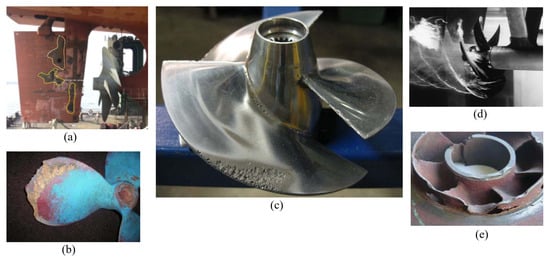
Figure 1.
Destructive effects caused by unsteady cavitation observed in marine applications and hydraulic systems: (a) cavitation-induced erosion on a ship rudder, (b) cavitation damage on the surface of a propeller, (c) cavitation-induced erosion on a propeller, (d) tip-vortex cavitation around a propeller, (e) cavitation damage on pump blades. Adapted from Refs. [12,13].
Huang et al. [14] conducted a research study on passive control techniques for cavitation phenomena that develop around a marine propeller positioned at the stern of a ship. Vortex generators (VGs) were employed to regulate propeller cavitation and hull pressure variations. The results suggested that a vortex generator with appropriate geometry may render an extremely non-uniform wake more uniform. Furthermore, the vortex generator can alter propeller cavitation and potentially diminish pressure variations. Chen et al. [15] conducted an experimental investigation of NACA66 hydrofoil to quantify the effect of a micro vortex generator (mVG). They utilized two distinct mVGas, designated as mVG-1, which was situated upstream of the separating zone of the hydrofoil, and mVG-2, which was kept at the separating point of the hydrofoil. Their findings demonstrated that mVG-1 can facilitate faster cavitation inception, while mVG-2 may postpone it, particularly in scenarios with smaller attack angles compared with the hydrofoil lacking cavitation control.
2. Hydrodynamic Cavitation Passive Control Methods
Before dealing with cavitation control using passive methods, in this section, the factors that cause an unsteady cavitation mechanism are briefly discussed so that readers can better understand how these mechanisms of unsteady cavitation formation may be controlled. Unsteady cloud cavitation and the mechanisms of the associated cavitation instabilities have been widely studied experimentally and numerically in [16,17,18,19,20,21]. Prior studies have shown that the transition to unsteady cloud cavitation is significantly influenced by a re-entrant jet [22,23,24,25]. The re-entrant jet flow typically ascends upward beneath a connected cavity owing to a negative pressure gradient at the closure zone of the cavity. The re-entrant jet was oriented perpendicular to the termination of an associated cavity interface [26]. A cavitation cloud may form downstream after the re-entrant jet severs the attached cavity near the hydrofoil’s leading edge, causing the attached cavity structure to roll up.
2.1. Vortex Generators (VGs)
Kadivar and el Moctar [27] conducted a detailed analysis of a passive controlling method’s impact on mitigating cavitation over an established hydrofoil. They employed a wedge-type vortex producer to regulate the transient cloud cavitation. Their findings demonstrated that selecting an appropriate size and placement of a wedge-type vortex generator on a hydrofoil helps alleviate wall-pressure peaks and turbulent velocity fluctuations. Researchers showed that a wedge-type vortex generator can transform large-scale cloud cavitation into a more stable attached cavity on a hydrofoil’s surface. In addition, the lift-to-drag ratio was improved for the hydrofoil with the optimal size and location of the vortex generator. Javadi et al. [28] numerically studied the application of bubble generators in two-dimensional cavitation modelling. They utilized a vortex generator (VG) on the hydrofoil and showed that the vortex generator may induce a lesser pressure recirculation zone back of the vortex generator. Their results show that the vaporization, bubble formation, and bubble collapse can be influenced and the force fluctuations may be mitigated.
Kadivar et al. [29,30] adapted a passive control method from the aerospace engineering application and used it to control cavitation in the marine engineering contexts. They employed cylindrical cavitating-bubble generators, a form of small vortex generator, to regulate the cloud cavitation’s erratic behavior. Their findings indicated that cylindrical cavitating-bubble generators can alleviate cloud cavitation instabilities and pressure pulsations. The cavity structure was modified to a stable configuration on the suction side of the hydrofoil across various cloud cavitating regimes. In addition, Kadivar et al. [31] performed numerical and experimental studies to mitigate the cavitation surge on a semi-circular leading-edge flat plate. Che et al. [32,33,34,35] investigated the influence of micro vortex generators on the unsteady cavitation dynamics of an NACA0015 hydrofoil. Their findings indicated that the micro vortex generators have significant ability to regulate the dynamics of associated cavitation. Furthermore, they demonstrated that the micro vortex generators may mitigate laminar separation in non-cavitating conditions and can rectify cavitation inception, resulting in more stable flow structures. Moreover, they stated that the hydrofoil modification may exert a minor influence on the transitional cavity oscillation due to the intrinsically unstable flow characteristics.
Qiu et al. [36] experimentally investigated the effects on the cavitation-induced erosion of the micro vortex generators over an NACA0015 hydrofoil. They demonstrated that the small vortex generators mitigated the periodic cavity shedding. The maximum impact on hydrofoil energy with the passive control method was about 48% of that of the hydrofoil without vortex generators. Additionally, the hydrofoil’s vortex generators helped to minimize the peak pressure variations as well as acoustic power by 32% and 10.8 dB, respectively. Also, they reported a significant reduction in erosion at the leading edge. Kadivar et al. [37] conducted an experimental investigation on the influence of hemispherical vortex generators on the cavitation dynamics surrounding a hydrofoil surface. Their findings showed that the effects of hemispherical vortex generators at the cloud cavitation and transient cavitation regimes significantly reduced the amplitude of the pressure pulsations in the hydrofoil wake area behind the hydrofoil. Zhu et al. [38] investigated the cavitation-induced erosion and cavitation control using a microstructure at different scales on an NACA0015 hydrofoil. To achieve this goal, they utilized vortex generators (VGs) measuring 0.25 mm (micro VG) and 2.5 mm (large VG), positioned at the leading edge of the NACA0015 hydrofoil. The pressure signal results indicate that the vortex generators may modify the pressure fluctuation period and diminish the primary frequency amplitude in comparison to the hydrofoil lacking a control technique. In addition, they showed that a superior suppression of pressure fluctuations can be obtained using the larger VGs. Furthermore, a reduction in erosion risk on the hydrofoil can be seen for the hydrofoil with the VGs due to the reduction in the large-scale cloud cavitation. The larger VGs demonstrated superior effectiveness in preventing cavitation erosion.
Velayati et al. [39] conducted a computational study with large eddy simulation (LES) to assess how adding surface contours influences cavitation dynamics on a Clark Y hydrofoil, with the purpose of stabilizing cloud-type cavitation. They arranged dome-shaped features at three different chordwise points. The analysis revealed that when these elements were placed close to the front edge of the hydrofoil, the sheet cavity became longer and the frequency of cloud shedding was reduced by around 5%. This adjustment, however, also produced an 11.45% growth in the drag-to-lift ratio. In contrast, relocating the rounded features toward the rear edge yielded a 2.5% enhancement in lift-to-drag performance but simultaneously raised the shedding frequency by 19.4%. Figure 2 illustrates a schematic of bio-inspired riblets applied near the leading edge on the suction side of a hydrofoil for passive cavitation control.
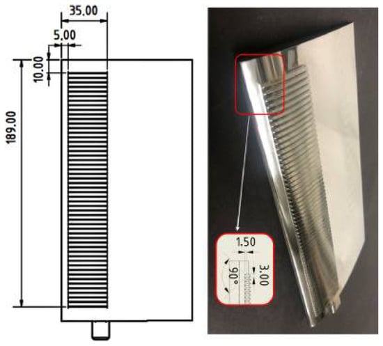
Figure 2.
Schematic view of mesoscale bio-inspired riblets which are employed on the suction side of a hydrofoil adjacent to the leading edge as a passive control method. Adapted from Ref. [40].
2.2. Obstacles
Kawanami et al. [23] performed experimental investigations on cloud cavitation dynamics and its control by introducing obstacles on hydrofoil. In this work, the obstacle was used to suppress the re-entrant jet and prevent the generation of cloud cavitation downstream of the hydrofoil. In addition, they presented that the cavitation-induced noise intensity and the hydrofoil drag were significantly reduced. Pham et al. [41] performed experimental work to study the unsteady sheet cavitation and cloud cavitation mechanisms. In addition, they used a tiny obstacle (barrier) on the hydrofoil to control cloud cavitation. Their findings demonstrated that this method can mitigate the amplitude of cavitation instabilities. Hofmann [42] experimentally studied different measures to control cloud cavitation. He examined various geometries of the blunt trailing edges of a semicircular leading-edge flat plate. He analyzed the effects of an obstacle mounted on a flat plate on the reduction in the cavitation-induced erosion.
Zhao et al. [43] performed an investigation around a 2D NACA0015 foil, both without and with obstructions. They employed various configurations of the barriers on the hydrofoil to manage the unstable cavitation. The study revealed that while lift and drag may be reduced, the lift-to-drag ratio can be enhanced for the hydrofoil by optimal sizing and positioning of the obstacles. Kim et al. [44] and Watanabe et al. [45] examined the influence of an axis-asymmetrical barrier plate positioned upstream of an inducer intake on the unsteadiness of cavitation surge to mitigate cavity instability. Ganesh et al. [46] conducted an experimental study on the effect of a barrier situated within a partial cavity on cavitation dynamics. They employed X-ray densitometry as a flow visualization technique to investigate the dynamics of bubbly shock fronts in cavitating flow. Their findings revealed that the local impact of low sound speed occurs once the cavity length exceeds the obstruction. They utilized an X-ray densitometer as a flow visualisation mechanism to study the dynamics of bubbly shock fronts in the cavitating flow. Their findings demonstrated that once the cavity length crosses the obstacle, the effect of low sound speed becomes localized. Zhang et al. [47] experimentally studied the cloud cavitation dynamics on a flat hydrofoil using the mounting of an obstacle downstream of the hydrofoil. They found that cloud cavitation shedding becomes weak with obstacles. In addition, they observed from the numerical results that the obstacle as a passive control method can reduce the strength and direction of the transient re-entrant jet and the pressure fluctuations on the flat hydrofoil.
Qiu et al. [48] used slits to control the periodic characteristics of unstable cloud cavitation on a hydrofoil. They showed that the high-speed jet induced from the slit can diminish the momentum of the re-entrant jet and may significantly reduce the complete detachment of the attached cavitation. In addition, their finding revealed that the primary frequency of cavitation pulsations can be reduced by 48.5% for the hydrofoil with cavitation control. Lin et al. [49] performed a numerical simulation to study the cavitation over flat hydrofoils using arc obstacles. They also employed large eddy simulation (LES) to model cavitating flows around the hydrofoil. Their study revealed that different types of surface obstacles could influence both the air distribution on flat hydrofoils and the frequency of cavitation shedding. Additionally, the presence of arc-shaped obstacles helped stabilize cavitation behavior and hinder its development on the hydrofoil surface. Similarly, Li et al. [50] conducted experiments to control unsteady cavitation around oscillating hydrofoils using spanwise obstacles near the trailing edge. These obstacles were found to generate a favorable torque on the hydrofoil, reducing the peak negative torque, while also effectively suppressing the growth of unstable cavitation and decreasing cavitation-induced noise within the flow.
2.3. Roughness
Coutier-Delgosha et al. [51] experimentally studied the roughness impact on the unsteady cavitation. It was found that the rough surface mounted on the immersed hydrofoil can rearrange the cavitation cycle in the sheet cavity structure. Hao et al. [52] investigated the influence of a surface roughness on the unsteady cloud cavitation flow around hydrofoils using high-speed video and particle image velocimetry (PIV). They indicated that the cloud cavitation mechanism, cavity structure, velocity, and vorticity distribution of the cloud cavitation may be changed compared to the hydrofoil without roughness. Chen et al. [53] conducted an experimental study on the regulation of cavitation patterns and associated hydrodynamics of the NACA66 hydrofoil by the use of leading edge roughness. Their findings suggest that leading edge roughness may influence hydrodynamic performance at sub-cavitation levels and can regulate the onset of cavitation inception.The hydrofoil without leading edge roughness had a higher lift coefficient than the hydrofoil with leading edge roughness, while the hydrofoil with leading edge roughness had a delayed angle for the maximum lift-to-drag ratio. Svennberg et al. [54] conducted an experimental investigation on the reduction in tip vortex cavitation through regulated surface roughness. The study showed that implementing an optimized roughness pattern on the hydrofoil could lower the cavitation number required for initiating tip vortex cavitation by approximately 33% compared to a smooth hydrofoil, although this was accompanied by a 2% increase in drag. Nichik et al. [55] carried out experimental research on controlling cavitation and modifying turbulence characteristics in the cross-flow around a circular cylinder, focusing on surface morphology and wettability effects. Their results demonstrated that introducing surface roughness significantly suppressed cavitation on the cylinder. They further observed that smaller-scale surface irregularities had a stronger influence on the examined wall structures. Additionally, both types of roughness were found to alter the turbulence characteristics of the wake, including mean velocity, turbulence intensity, and higher-order statistical moments of fluctuations.
2.4. Grooves, Riblets and Slots
Choi et al. [56] proposed a passive technique for regulating and reducing cavitation in the inducer by implementing J-Grooves. The suction performance of the inducer can be markedly enhanced over the majority of flow regimes. Danlos et al. [57,58] performed an experimental study to analyze the effects of surface roughness, such as grooves, on the cavitation in a venturi-type geometry. They used a proper orthogonal decomposition to study the effects of the grooves on the cavitation dynamics. They found that the grooves may suppress the flow unsteadiness linked with the cloud cavitation shedding on a venturi-type geometry. In addition, a reduction in the cavity sheet length and mitigation of the cloud cavitation shedding can be obtained by an optimal size of the grooves. Kamikura et al. [59] numerically studied the control of the cavitation instabilities using asymmetric slits on the inducer blades. They indicated that the asymmetric slits can act as a passive cavitation control method for controlling cavitation instabilities. Figure 3 shows a schematic representation of a cylinder without cavitation control and with the vertical and horizontal scalloped riblets which can be used as a passive control method for cavitation control. The geometry and construction of the riblets may play an important role in the flow control. Cheng et al. [60] investigated the suppressing of tip-leakage vortex cavitation by overhanging grooves. Their results demonstrated that the fluctuation of the tip-leakage vortex cavitation may be successfully reduced by overhanging grooves. However, no substantial change of the mean drag and lift was observed due to overhanging grooves.
Kadivar et al. [61,62] and Kumar et al. [63] performed investigations into the cavitation dynamics of both a smooth cylinder and cylinders including sawtooth and scalloped mesoscale riblets utilizing high-speed visualization and force fluctuation measurements. Their findings indicated that the riblets can regulate flow dynamics and von Karman vortex features while also mitigating cavitation-induced vibrations of the cylinder. Moreover, both riblet designs significantly reduced lift force fluctuations and diminished cavitation-induced vibration by approximately 41% for sawtooth riblets and 43% for scalloped riblets. Jia et al. [64] investigated the cavitating flow on NACA66 with a V-shaped groove and found the impact on broadband noise. The V-shaped groove could prolong a cycle of cavitation shedding and decrease the mean cavitation volume during a period by 17.46%. Moreover, it was found that the groove could diminish the average dipole noise on the hydrofoil surface by 5.07% and the average quadrupole noise in the center longitudinal section by 6.86% during a cavitation cycle. Qiu et al. [65,66] investigated the effect of the micro vortex generators on cavitation collapse and pressure pulsation on an NACA0015 hydrofoil. Their findings demonstrated that the lift-to-drag ratio may be optimized and the stability of the flow field may be augmented by the influence of the micro VGs. Furthermore, a reduction in pressure pulsation was seen for the hydrofoil equipped with micro vortex generators positioned at the leading edge. Moreover, the shedding and failure of the cloud cavity on the smooth hydrofoil were substituted by the partial detachment and collapse of sheet cavitation on the hydrofoil equipped with micro VGs in the cloud cavitating regime.
Bio-inspired riblets were used in an experimental study by Lin et al. [67] and Kumar et al. [40] to regulate partial and cloud cavitation on an NACA0015 hydrofoil. To achieve this objective, they applied two distinct types of bio-inspired riblets, namely, scalloped riblets and sawtooth riblets. This study revealed a reduction in noise for the hydrofoil, including scalloped and sawtooth riblets in the low-frequency domain and, in certain instances, at higher frequency ranges. They found that the cavitation oscillation process can be controlled and that large-scale cavitation structures may be eliminated by passive control methods. Their findings show that cavitation shedding was substantially alleviated due to a decrease in the momentum of the re-entrant jet. Biswas et al. [68] conducted a numerical simulation to investigate the unstable cavitation effects on the hydrodynamic performance of the NACA4412 hydrofoil featuring a triangular slot. The modified hydrofoil demonstrated superior management of cavitation phenomena compared to the unmodified hydrofoil at reduced cavitation numbers. At elevated cavitation levels, the base hydrofoil may provide marginally superior performance compared to the hydrofoil with a triangular slot regarding the lift-to-drag ratio. Furthermore, they demonstrated that stalling may be mitigated for the hydrofoil through the application of a passive control approach.

Figure 3.
Schematic view of a cylinder, (1) without cavitation control, (2) with vertical scalloped riblets cylinder and (3) with horizontal scalloped riblets. Adapted from Ref. [63].
2.5. Leading- or Trailing-Edge Modification for Passive Control
Ausoni et al. [69,70] performed an experiment to study the effects of a hydrofoil on the dynamics of the cavitation. Their results revealed that a more organized vortex shedding with the reduction in the vortex shedding frequencies was obtained using the blunt trailing edge. Custodio et al. [71] performed experimental work to analyze the cavitation dynamics and hydrodynamic efficiency of the hydrofoils without and with wavy leading edges. They evaluated multiple advanced leading edge configurations using three distinct amplitudes of 2.5%, 5%, and 12%, together with two wavelengths corresponding to 25% and 50% of the chord length. Their findings indicated that cavitation on hydrofoils equipped with cavitation control can occur at a reduced angle of attack compared to hydrofoils lacking wavy leading edges. Furthermore, the lift coefficient of the simple hydrofoil was either higher than or equal to that of the hydrofoils with wavy leading edges.The drag for the modified hydrofoils with the lower amplitude of the wavy leading edges was equal to the unmodified hydrofoil. Li et al. [72] numerically analyzed cavitation around hydrofoils by incorporating humpback-whale-inspired leading-edge undulations. Their simulations demonstrated that introducing a sinusoidal edge improves the lift-to-drag performance while cutting the cavitation volume by nearly 30%. They also observed that increasing the undulation amplitude can reduce pressure oscillations by close to 60%. In another investigation, Arab et al. [73] carried out experiments on an NACA0012 hydrofoil manufactured through additive 3D printing, where movable flaps were attached to the front and rear edges. Results indicated that flap deflection enhanced lift generation and suppressed cavitation volume. Furthermore, the hydrofoil fitted with a parabolic flap produced higher lift compared with a conventional flap design and extended the operational range without cavitation to some extent.
The effects of surface curving and leading-edge protrusion on cavitation and cavitation-induced noise in partially cavitating twisted hydrofoils were experimentally investigated by Çelik et al. [74]. Their findings indicated that the tubercled model generated a noise level comparable to or somewhat exceeding that of the corrugated model in the mid-frequency spectrum. Furthermore, they noted that the tubercle hydrofoil could demonstrate the minimal cavitation area and duration, roughly 70% and 50% of those seen in the normal and corrugated models, respectively. Xue et al. [75] performed a numerical analysis of the cavitating flow around an NACA0015 foil including bionic advanced protuberances using large eddy simulation (LES). The bionic hydrofoil surface exhibited a greater number of small vortex cores, which impeded the development of big vortices near the leading edge of the hydrofoil. The vortex intensity generated by cavity shedding was greater for the baseline hydrofoil than for the bionic hydrofoil. Usta et al. [76] developed a computational model to analyze how surface corrugations and leading-edge tubercles influence cavitation behavior on a twisted NACA0015 hydrofoil. Their findings indicated that the corrugated hydrofoil might attain superior efficiency compared to other layouts at several angles of attack in non-cavitating situations. They demonstrated that corrugated and tubercled hydrofoils can gradually enhance their performance at elevated angles of attack in cavitating situations. Their results indicated that incorporating tubercles can postpone stall onset and reduce the cavitating region across various angles of attack compared with the reference hydrofoil.
Figure 4 shows a schematic view of a cylinder without cavitation control and with two different surface morphologies, such as a rough surface and a finned surface.
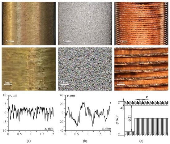
Figure 4.
Schematic view of a cylinder without control methods and with different surface morphologies as passive cavitation control methods. Visual appearance (top row), close-up view (middle row) and characteristic surface profiles (bottom row) of the (a) smooth cylinder, (b) rough cylinder and (c) finned cylinder. Adapted from Ref. [55].
Table 1 shows the summary of previous works in the fields of cavitation passive control methods.

Table 1.
Summary of researches for cavitation passive control methods.
Figure 5 represents the photographs of the cavity structures on the surface and in the wake of the cylinders for three types of wall morphology: smooth, rough, and finned.
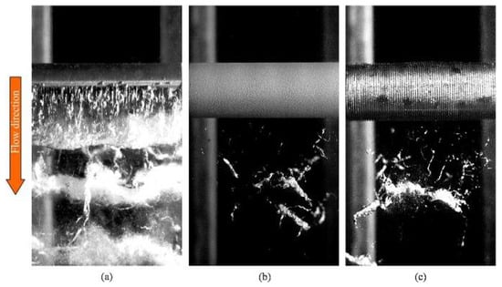
Figure 5.
Photographs of the cavitation dynamics on the surface and in the wake of the cylinders for three wall morphologies, (a) smooth; (b) rough and (c) finned. Adapted from Ref. [55].
2.6. Other Methods for Passive Control
Regarding the other works of control of cavitation using passive methods, the following works are discussed. Crimi [77] experimentally investigated the effects of hydrofoil sweep angle on the performance with cavitation. He indicated that the sweep angle can reduce the generated erosion on the surface. Onishi et al. examined the influence of hydrophilic and hydrophobic coatings on the cavitation dynamics surrounding a hydrofoil [78]. They observed that the hydrophilic coating may reduce the incipient cavitation number. In addition, the hydrophilic nature of textures can lead to a lower growth of cavitation at small attack angles. Petkovsek et al. [79,81] performed the unsteady cavitation dynamics analysis for the cylinder without and with passive control methods. They tested five different surface shapes (dimpled, velvet, oxidized, waved, and grooved) on the surface of the cylinder. The cavitation properties may considerably depend on surface texture and surface wetting. They concluded that cavitation on the cylinder can be mitigated using an appropriate laser-texturing parameter. Amini et al. [80] performed an experiment to study a passive control method for suppression of the tip vortex cavitation. They employed several winglets on the hydrofoils, demonstrating that these winglets can significantly augment the dimension of the tip vortex and postpone the onset of cavitation.
Zhao and Wang [83] conducted a numerical investigation on the passive management of cloud cavitation utilizing a bionic fin–fin structure on an NACA0015 hydrofoil. They reported a decrease in the hydrofoil’s average drag and a reduction in its lift. The bionic structure applied to the hydrofoil’s surface enhanced the lift-to-drag ratio. Furthermore, the bionic shape can significantly decrease kinetic energy, resulting in a more stable flow compared to the hydrofoil lacking a bionic structure. Yang et al. [84] numerically examined a passive cavitation control method by incorporating two bio-inspired structures into a hydrofoil design. Their analysis revealed that this integrated configuration suppressed cavitation development and lowered the total cavity volume by about 43%. In addition, the approach enhanced flow-field stability, reducing fluctuations in the pressure coefficient on the suction side of the hydrofoil by nearly 46.55%. Figure 6 shows a schematic view of a polished cylinder and laser-textured cylinders with various surface morphologies, such as dimpled, velvet, oxidized, waved and grooved surface, using a scanning electron microscope (SEM) and a 3D optical Infinite-Focus Measuring (IFM) device. Kumar et al. [85] numerically investigated the cavitation control on an NACA0018 hydrofoil using a surface cavity mounted on the suction surface of the foil. According to this study, an enhancement of about 7% and 3.1% in the lift-to-drag ratio was obtained for the hydrofoil with a surface cavity compared to the unmodified hydrofoil at high and low cavitation numbers, respectively.
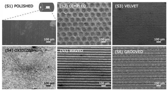
Figure 6.
Schematic view of a polished cylinder and laser-textured cylinders with various surface morphologies such as dimpled, velvet, oxidized, waved and grooved surface. Adapted from Ref. [81].
Figure 7 shows a schematic view of a basic hydrofoil model based on the NACA634–021 airfoil and bionic hydrofoils with a fin spine structure, sinusoidal leading edge, and a combined hydrofoil model constructed by combining two single bionic structures with sinusoidal leading edge.
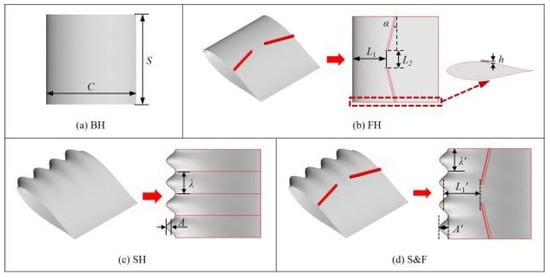
Figure 7.
Schematic view of a basic hydrofoil model (a) based on the NACA634–021 and bionic hydrofoils (b) and sinusoidal leading edge (c) and a combined hydrofoil model constructed by modify both with sinusoidal leading edge (d). Adapted from Ref. [84].
3. Hydrodynamic Cavitation Active Control Methods
In several previous studies, active methods of cavitation control were studied. The most important methods used were the cavitation active control using air injection and water injection. In this section, the relevant works in this field are reviewed.
3.1. Air Injection
Arndt et al. [86] performed analysis on cavitation-induced erosion on the surface of an elliptic hydrofoil using an active control technique. They injected air through small holes on the hydrofoil surface. Their findings demonstrated that the air injection method can effectively mitigate the cavitation-induced erosion. Reisman et al. [87] carried out experiments on air injection as a means of controlling cloud cavitation dynamics, aiming to suppress low-frequency pressure fluctuations. Pham et al. [41] experimentally investigated the control of the unsteady sheet cavitation and cloud cavitation mechanisms. They used an air injection through a slit on the hydrofoil surface to control cloud cavitation. Their findings revealed that the effects of air injection can reduce the amplitude of cavitation instabilities. Hofmann [42] experimentally studied the effects of an air injection on cavitation instability. He showed that the cavitation-induced erosion can be mitigated using the air injection in the cavitation zone. Ceccio et al. [88] showed that friction drag can be diminished through gas injection, resulting in the formation of a bubbly mixture that alters the flow structure within the turbulent boundary layer. The investigators demonstrated that partial cavity flows can also mitigate friction drag on a horizontal surface. They showed that application of the active techniques can be used for underwater vehicles and surface ships.
Zhang et al. [89] examined how air injection affects the behavior of unsteady cloud cavitation flows. They found that the ventilation method can damp pressure pulses induced by cloud cavity collapses in a converging–diverging channel and stabilize the attached cavity. Mäkiharju et al. [90] studied the effects of injecting non-condensable gas on the dynamics of partial cavity formation. Their experimental results illustrated that the gas injected near the apex of a convergent–divergent channel may increase the pressure near the suction peak and, thereby, suppress the vapor formation and reduce the overall cavity void fraction. Wang et al. [91] investigated the vortex shedding dynamics in a ventilated cavitating flow and indicated that the gas injection has a significant effect on the velocity and vorticity distributions. Using a proper orthogonal decomposition (POD) analysis, they found that the gas injection mainly affects the first mode of vortex shedding in the wake. Wang et al. [92] reported that introducing air can extend the attached cavity length and enlarge cloud cavity structures in unsteady cavitation flows. The influence was observed to intensify as the air injection rate increased.
Malekshah et al. conducted an investigation of the morphological and dynamic character of cavitation caused by varying air injection rates and places (Malekshah, 2023). The injection site significantly affects the cavitation dynamics and shape; however, the efficacy of air injection may be contingent upon the flow circumstances. Hilo et al. [93] performed an investigation on the regulation of cavitating flow and its associated noise using air injection. They evaluated the positioning of the air injection and the rate of air injection for the regulation of cavitation. Their findings suggested that injecting air nearer to the leading edge may provide the most substantial influence on diminishing noise. Furthermore, they discovered that introducing air at the midpoint of the foil’s chord might diminish the length of the vapor sheet cavity by 27%. The volume of the ventilated cavitation can be augmented by enhancing the air injection rate. Singh et al. [94] performed an experiment to investigate the cavitation dynamics within a converging–diverging nozzle utilizing air injection at various injection locations. They assessed the cavitation length, cavity area, and energy distribution. Their findings showed that the lengths and distributions of bubbles within the channel may be modified by adjusting the injection locations. They demonstrated the pivotal significance of the injection site in enhancing cavitation efficiency within the converging–diverging nozzle. Hilo et al. [95] performed laboratory experiments to evaluate how injecting air at the front edge of a three-dimensional hydrofoil affects cavitation-related noise. Their observations showed that as the rate of air supply increased, the frequency of sheet-cavity shedding declined in an almost linear fashion, implying that flow fluctuations became weaker under stronger ventilation. A modest rise in drag was recorded when air was introduced. Moreover, the study highlighted that air injection tends to raise the acoustic pressure at frequencies below 1 kHz. Sun et al. [96] carried out a numerical simulation of cavitating flow over an NACA66 hydrofoil, concentrating on how ventilation affects cavitation dynamics. They investigated the dynamics of cavities, the structure of vortices, and the wake field. A Schnerr–Sauer cavitation model and a large eddy simulation (LES) approach were employed to simulate cavitation both with and without ventilation. Their findings indicated that the shedding frequency of the vented cloud structures might exceed that of natural cavitation. Furthermore, the ventilation can significantly diminish both the turbulence strength and the turbulence integral scale in the hydrofoil’s wake. The ventilation may enhance the velocity pulsation and instability of the cavitation. Luo et al. [97] performed a numerical analysis to examine the interaction between vortex dynamics and turbulent flow in a ventilated cavitation on an NACA0015 hydrofoil using large eddy simulation.
3.2. Water Injection
Wang et al. [98] investigated the water injection for control of cloud cavitation on an NACA0066 hydrofoil. The researchers examined the orientation and trajectory of the water jet concerning the cavitation dynamics on the hydrofoil. Their findings indicated that water injection can enhance the velocity gradient in the boundary layer and potentially diminish the degree of flow separation on the hydrofoil. Additionally, they presented that the velocity of the re-entrant jets can be mitigated due to the effects of the water injection. Timoshevskiy et al. [99] investigated the effects of active cavitation control through the injection of a liquid along the surface. They established that an active control strategy can alleviate cavitation and diminish the amplitude of pressure pulsations through water injection. They attempted to control cavitation on the surface of a scaled-down model of guide vanes of a hydraulic turbine using a wall jet of water that was injected through a spanwise slot nozzle along the wall, depending on injection rate. In addition, their results revealed that the active control method based on water injection is capable of mitigating cavitation and reducing the amplitude of pressure pulsations caused by the unsteady cavitating flow. They presented that the attached cavity length can be reduced by 25% compared to the case without injection. Wang et al. (2020) conducted an experimental investigation with water injection for cavitation reduction in an NACA66 (MOD) hydrofoil. The researchers examined the impact of water injection on cavity formation using four types of jet flow at two distinct jet locations. Their results indicate that water injection can obstruct the upstream movement of the re-entrant jet and may reduce its momentum. The longest sheet cavity length was diminished by 79.4%, and shedding is alleviated with an injection flow rate coefficient of 0.0245 and a jet position of 0.45C. In numerical simulation, researchers conduct several tasks. Wang et al. [100] examined the influence of the placement of water injection holes on the control of cavitation flow over the NACA66(MOD) hydrofoil. Their studies demonstrated that the effectiveness of cavitation suppression is closely associated with the porosity of the jet orifice. Their findings suggest that the double-row jet hole structure in a front trapezoidal arrangement may markedly improve cavitation reduction and hydrodynamic performance. Furthermore, 155° jet holes positioned along the leading edge generated increased pressure while diminishing the lift of the hydrofoil. Yan et al. [101] numerically studied the influence of active jet parameters on the cavitation performance of Clark-Y hydrofoil. They used the large eddy simulation combined with the Zwart–Gerber–Belamri cavitation model to simulate the cavitating flows. Their results showed that the active water jet can block the re-entrant jet and reduce the cavity volume on the hydrofoil when the jet position is located at the leading edge of the hydrofoil. However, this effect may reduce the lift coefficient of the hydrofoil. According to this study, the hydrofoil’s lift–drag ratio may rise by 11.4% with the ideal jet arrangement. Moreover, the percentage of cavitation volume was reduced by 30% relative to the baseline hydrofoil.
Gu et al. [102] conducted a numerical investigation on the regulation of cavitation in fluid machinery under high-velocity flow circumstances, employing a shark gill slit jet construction inspired by bionic principles. The jet orientation aligns with the primary flow direction, but at varying places on the hydrofoil. The findings demonstrated that the time-averaged volume fraction decreased by 46% relative to the primary hydrofoil at a jet position of 0.6C. The lift-to-drag ratio of the jet hydrofoil was enhanced relative to the primary hydrofoil, and the pronounced shock wave was substantially reduced. Moreover, cavitation management can transform lift–drag pulsation from low-frequency, large-amplitude to high-frequency, small-amplitude. Wang et al. [103] conducted analysis on the regulation of cloud cavitation surrounding an NACA66 hydrofoil using active water injection. The study revealed a 49.34% reduction in cavitation volume and an 8.55% gain in the lift–drag ratio at the best water injection parameter of 0.30C with a jet angle of 60 degrees. Yan et al. [104] conducted an analysis of the regulation of cavitation on a Clark-Y hydrofoil utilizing a biomimetic water jet. Their findings indicated that the lift-to-drag ratio can be enhanced by 16.4% through the optimal implementation of water injection in conjunction with a passive bioinspired structure. Li et al. [105] conducted a numerical investigation of the cavitating flow surrounding an NACA66 hydrofoil utilizing large eddy simulations and the acoustic analogy approach. They employed active water injection in conjunction with barchan dune vortex generators to mitigate cavitation-induced noise. The researchers discovered that the cavitation volume can be diminished by nearly 90% in some cavitating regimes, while monopole and dipole noise can be attenuated by 9.25 dB and 5.23 dB, respectively. Furthermore, a 15.47% improvement in the lift-to-drag ratio was seen for the hydrofoil equipped with passive control barchan dune vortex generators. Moreover, the lift-to-drag ratio was enhanced by 64.54% for the hydrofoil by the utilization of water injection in conjunction with barchan dune vortex generators for control. Li et al. [106] performed a numerical simulation to control cloud cavitation using an active control method. They used a water jet at various stages of attached cavitation development on an NACA66 (MOD) hydrofoil to analyze the effects of intervention position and jet dynamics on cavitation control. They set the jet positions on the hydrofoil at 0.19C (named H019C), 0.30C (named H030C), and 0.45C (named H045C) from the leading edge. Their results revealed that the re-entrant jet strength for H019C, H030C, and H045C were reduced by 43.44%, 54.96%, and 49.47%, respectively, compared to the original hydrofoil without a control method. Furthermore, an improvement in the lift-to-drag ratio was observed for H019C, H030C, and H045C of 0.30%, 8.44%, and 12.30%, respectively. Ji et al. [107] numerically studied the water injection on tip leakage vortex cavitation for a hydrofoil. For the numerical simulation of the cavitating flows, they used a large eddy simulation combined with the Schnerr–Sauer cavitation model. According to this study, the tip leakage vortex was significantly reduced using the water injection, and the drag coefficient was mitigated by 3.5%. In addition, a reduction of about 15.40% in the maximum circumferential velocity of the tip leakage vortex was obtained with the cavitation control. Figure 8 shows a schematic view of a hydrofoil without injection and with water injection as an active cavitation control method.
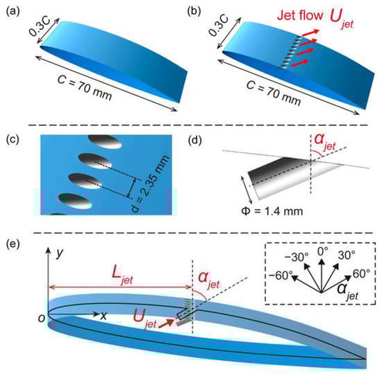
Figure 8.
Schematic view of a hydrofoil with water injection as an active cavitation control method. (a) Original hydrofoil without injection, (b) Modified hydrofoil with water injection, (c) Details of the jet hole distance, (d) Diameter of the jet hole and (e) Graphical interpretation for three variable parameters. Adapted from Ref. [103].
Figure 9 shows a schematic representation of a test section of an air injection as an active cavitation control method on a convergent–divergent channel. Figure 10 illustrates the experimental results of typical cloud cavitation dynamics on a convergent–divergent channel using different air injection rates.
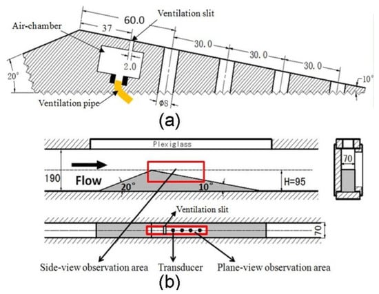
Figure 9.
Schematic view of a test section of an air injection as an active cavitation control method on a convergent–divergent channel. (a) A transducer mounting and ventilation slit and (b) test section and test model of convergent–divergent channel. Adapted from Ref. [89].
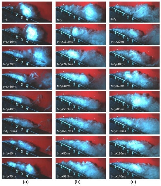
Figure 10.
The experimental results of cloud cavitation dynamics on a convergent–divergent channel under different injection rates: (a) without injection; (b) with air injection rate Qv = 1.135 × 10⁻³; and (c) with air injection rate Qv = 2.27 × 10⁻³. Adapted from Ref. [89].
Table 2 shows the summary of previous works in the fields of cavitation active control methods.
Table 2.
Summary of researches for cavitation active control methods.
3.3. Other Active Methods to Control Cavitation
The effects of polymer injection on the dynamics of vortex cavitation have been studied [108,109,112]. Their results revealed that the pressure in the vortex core can be increased with this control technique by reducing the maximum tangential velocity along the vortex, thus delaying the cavitation inception. De Giorgi et al. [113] conducted a numerical investigation of an active control technique for unstable cavitation utilizing a single synthetic jet actuator surrounding an NACA0015 hydrofoil. Their findings demonstrated that the synthetic jet management method can achieve a reduction of 34.6% in average vapor content and 17.8% in average torsional load, respectively. Wang et al. [114] investigated how an actively controlled flexible surface influences and constrains cloud cavitation around a hydrofoil. Piezoelectric actuators with varying amplitudes and frequencies of actuation drive the flexible surfaces at three representative locations along the hydrofoil. They indicated that the cavity shedding mode from a large-scale shedding was changed to a small-scale shedding at the cavity closure with the cavitation control near the leading edge. Figure 11 shows a schematic view of a hydrofoil with water injection as an active control method for cavitation.
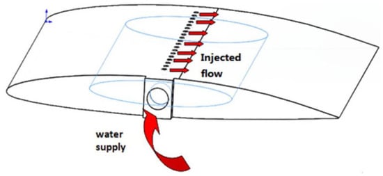
Figure 11.
Schematic view of a modified NACA66(MOD) hydrofoil with water injection as an active control method for control of the unsteady cavitation. Adapted from Ref. [100].
4. Conclusions and Perspectives
This review provides an overview of the previous numerical and experimental works on the cavitation control using passive and active methods. As presented in the state-of-the-art, there are different methods of passive and active flow control methods, including sweep angle of foil, roughness, bio-inspired riblets, V-shaped, J-grooves, obstacles, surface roughness, blunt trailing edge, slits, various vortex generators and triangular slots, air injections, water injections, polymer injections, synthetic jet actuators, and piezoelectric actuators. The main achievements of these numerical and experimental works in the field of cavitation control in marine engineering applications can be summarized for the different destructive effects of the cavitation as follows:
4.1. Control of Cavity Structures
4.1.1. Passive Method
In the case of using various types of vortex generators (VGs), the results mostly indicated that by choosing a proper size and location for the vortex generator on a hydrofoil, cavitation volume can be reduced on the hydrofoil surface. Some results indicated that an arc obstacle may stabilize the cavitation behavior on a flat plate. Furthermore, an axis-asymmetrical obstacle plate in the inducer inlet’s upstream can mitigate the cavitation surge unsteadiness. In addition, the asymmetric slits can also control the instability of the cavitation in an inducer. In the case of using roughness, the researchers presented that the roughness may rearrange the cavitation cycle and can manipulate the velocity and vorticity distribution of the cloud cavitation. In addition, some results revealed that the roughness may reduce the cavitation structures on a circular cylinder at different cavitating regimes. In addition, some other works found a reduction in tip vortex cavitation by 30% with a penalty of drag force of about 2% using roughness. Using an optimal shape of grooves, it can be observed that the flow unsteadiness with the cloud cavitation shedding can be mitigated on a venturi-type geometry. Some results revealed that the fluctuation of a tip-leakage vortex cavitation may be suppressed using overhanging grooves. Some investigators showed that the V-shaped groove may mitigate the average cavitation volume on the foil surface by around 17%. In the case of utilizing a hydrofoil with wavy leading edge, a mitigation of cavitation volume on the foil’s surface by 30% can be reached. In some works, they found that a tubercled hydrofoil can induce the lowest cavitation volume and period by about 70% and 50% compared to the unmodified hydrofoil and corrugated hydrofoil, respectively. Some achieved a reduction in the vortex shedding frequency using a blunt trailing edge. Using hydrophilic textures, a lower growth of cavitation can be obtained in the previous works. Furthermore, previous investigations have observed a delay in the cavitation inception process due to the use of winglets on hydrofoils. Utilizing two bionic structures, a cavitation volume reduction up to around 40% was presented in some studies.
4.1.2. Active Method
Some works indicated that cloud cavitation characteristics can be changed and the magnitude of pressure pulsation may be reduced for the cases using air injection in the small frequency range. Additionally, injecting air through a slit may control the pulsation of the cloud cavity structures. Utilizing air injection, some works found that a reduction in the vapor cavitation and noise can be observed by air injection close to the leading edge of a foil. In addition, injecting air at the center of a hydrofoil surface may mitigate the size of the sheet cavity structures by around 20–30%. Furthermore, the attached cavity shedding rate can be reduced linearly with the enhancement of the air injection rates. According to the results of air injection in a converging–diverging nozzle, it was shown that the bubble length and distributions in the nozzle can be altered for different locations of the air injection. According to some results, a higher shedding frequency of the cloud cavity structures with air injection was observed compared to the case without air injection. In addition, the velocity pulsation and cavitation instability may be mitigated for the cases with optimal air injection. From some previous achievements, it can be seen that the water injection may enhance the velocity momentum inside the boundary layer and can control flow separation which can occur on an unmodified hydrofoil. Some researchers showed that the cavity structure may be mitigated on a hydrofoil using a water injection through a spanwise slot on the suction surface of the foil. They indicated that the length of the attached cavity may be mitigated up to 25% compared to the hydrofoil without water injection. Some other results revealed that the attached cavity length may be mitigated by around 70–80% with the water injection located at 0.45 of the foil’s chord. Some other studies found that the momentum of the re-entrant jet on the hydrofoil can be reduced using water injection on the modified foil. Some findings revealed that the unsteady cavitation can be suppressed using double-row water jet holes mounted in the forward trapezoidal structures. Using an optimal water injection system in a hydrofoil, the cavitation volume may be reduced by about 30% compared to the unmodified foil. Utilizing a shark gill slit water jet located at 0.6 of a hydrofoil chord, the cavitation volume may be mitigated by around 40–50% compared with the unmodified foil. Some results revealed that the cavitation volume can be reduced by over 90% in some cavitating regimes for a hydrofoil using a water injection combined with barchan dune VGs. Utilizing a water injection located at 0.19, 0.30, and 0.45 of the foil’s chord showed that a reduction in the speed of the re-entrant jet of up to 43%, 54%, and 49% can be obtained, respectively.
4.2. Control of Hydrodynamic Efficiency
4.2.1. Passive Method
In the case of using VGs, some works showed that the lift-to-drag ratio can be reduced by more than 10% using microstructures mounted close to the leading edge. However, an enhancement of the lift-to-drag ratio was observed of around 2.5% by some microstructures located near the trailing edge. In addition, using spanwise obstacles may generate a positive torque on the hydrofoil and can induce a reduction in the maximum negative torque. Some results indicated that the maximum lift-to-drag ratio can be delayed for the hydrofoil using roughness mounted on the leading edge hydrofoil surface. The utilization of J-grooves demonstrated an enhancement in the suction effectiveness of an inducer across various cavitating regimes. Some results indicated that sawtooth and scalloped riblets may mitigate the cavitation-induced vibration of a cylindrical cylinder by around 40% at different flow regimes. According to some of the previous results, a better performance of a hydrofoil with a triangular slot in terms of lift-to-drag ratio can be observed. According to some results using a wavy leading edge, the researchers indicated that an improvement in the lift-to-drag ratio may be obtained for the foil using a wavy leading edge. In addition, some works presented a delay stall and less cavitation for a tubercled hydrofoil. In the case of using wavy leading, the lift coefficient for an unmodified hydrofoil may be comparable to or greater than the foils with wavy leading edges. Using a bionic fin–fin structure, the average drag of the foil was mitigated, and the lift also was reduced. The results indicated that when using an optimal size and location of the VGs, the pressure fluctuations can be mitigated by around 30%. In addition, the pressure coefficient with two bionic structures can be reduced by around 40–50%.
4.2.2. Active Method
Some studies showed that using air injection on a hydrofoil can slightly enhance the drag force compared to cases without injection. Using a water injection, the pressure pulsation on a hydrofoil was reduced according to the results obtained in some of the previous studies. A higher pressure and lower lift force could be obtained for the hydrofoil with a 155° injection holes, as observed in some previous findings. Some works showed that the lift force of a hydrofoil may be reduced by water injection on a hydrofoil in some cavitating regimes. However, using an optimal water jet, an enhancement of the lift–drag ratio of up to 10–12% can be obtained. Some works found that the lift-to-drag ratio of a hydrofoil using a shark gill slit water jet can be improved compared to the foil without water injection. In addition, the amplitude and frequency of the lift and drag pulsations may be changed to a lower amplitude with a higher frequency for the foil with water injection. Some researchers indicated that the lift–to-drag ratio can be increased by about 8–10% for an optimal water injection located at 0.3 of the foil’s chord with the jet angle of 60 degrees. Some previous works showed that the lift-to-drag ratio can be enhanced by 16% using an optimal water injection located behind a bioinspired structure on the hydrofoil suction surface. Some works showed that a water injection with VGs may increase the lift-to-drag ratio by up to 60% for a hydrofoil, and a reduction of about 15% can be obtained for the lift-to-drag ratio by using only barchan dune VGs. According to the results of the previous studies, it can be deduced that the lift-to-drag ratios for a hydrofoil with water injection located at 0.19, 0.30, and 0.45 of a foil’s chord can be increased by around 0.30%, 8%, and 12%, respectively. The results revealed that the tip leakage vortex may be mitigated using the water injection, and the drag force can be reduced by 3–4%.
4.3. Control of Cavitation-Induced Erosion and Noise
4.3.1. Passive Method
Using the passive method VGs, the cavitation-induced erosion can be alleviated in some cavitating regimes. In the case of using obstacles, some works showed that an obstacle mounted on a flat plate may mitigate the cavitation-induced erosion. The acoustics induced by cavitation can be reduced by around 10 dB for the hydrofoil with the optimal size and position of the VGs on the suction surface. In the case of using grooves, a reduction in the average dipole noise and average quadrupole noise on the hydrofoil of 5–7% can be observed in the previous studies.
4.3.2. Active Method
According to the results using air injection via small holes, a reduction in the cavitation erosion was observed. Utilizing an air injection on a hydrofoil, it was mentioned that the sound pressure level at frequencies smaller than 1000 Hz can be captured on a hydrofoil using the air injection. Utilizing a water injection with barchan dune VGs, a reduction in the monopole and dipole noise of the hydrofoil can be observed of around 9 dB and 5 dB, respectively.
4.4. Future Perspectives
Based on the detailed literature, the passive or active cavitation control methods can control the dynamics of cavitation in various cavitation regimes. For moderate cavitation scenarios, including sheet and partial cavitation, various passive control strategies have been effectively applied to stabilize cavity formation by weakening the momentum of the re-entrant jet and minimizing the damaging influence of pressure pulsations on hydrofoils. However, for highly unstable cavitating flows such as unsteady cloud cavitation, the control of the cloud cavitation cannot be achieved by only passive methods. This condition can usually occur at higher propeller loading and higher ship speeds or at larger angles of attack of the hydrofoils. In addition, in the previous works, most of the numerical and experimental studies of the cavitation control were performed on the hydrofoils with low or medium angles of attack of about 5–8 degrees. Therefore, the active and passive cavitation control methods for the cases at higher angles of attack should be considered for future works.
Regarding the advantage of the passive flow control methods, it can be deduced that there is no requirement of energy, and a desired effect can be obtained by using the small changes like VGs, grooves, riblets, and obstacles on the surface of the hydrofoils. Under the severe cavitating conditions such as cloud cavitation and cavitation surge regime, the cavitation-induced instability can happen due to the re-entrant jets and also significant associated pressure waves propagating inside the cavity structures on the hydrofoils. In these severe cavitation conditions, passive control methods can only mitigate some re-entrant jets expanding in the streamwise direction; however, the stabilization of the cavity structure on the hydrofoil and a proper mitigation of the pressure pulsation on the hydrofoils cannot be achieved. In addition to the passive control techniques, the active control methods also require additional energy and, consequently, lead to higher costs for control of cavitation.
The ratio of drag to lift of the immersible bodies was not measured in the experimental works of the majority of the earlier research. In addition, the lift-to-drag ratio of the hydrofoils with cavitation control using active and passive methods was also not discussed in detail. Furthermore, these topics about the reduction in the cavitation-induced erosion and noise have been studied by few researchers, and the effects of the active and passive control methods were not investigated in detail. Therefore, these aspects should be considered by researchers in future studies. There are still significant research gaps that can affect the cavitation control in real cases. In addition, the following parameters could also be considered for future works: manufacturing processes of the passive, active, or combined control methods; cost of combined methods; lifetime and durability; scale effects; exchange of information and identification of cavitating flows on immersible bodies; and transfer to a combined active–passive control method for optimal cavitation control.
The results of previous numerical and experimental studies suggest that combined passive–active control methods may be the most effective approach for managing cavitation and its various undesirable effects. There are only some numerical works regarding the combined passive–active control methods; therefore, it is suggested to develop different combined passive–active control methods, using the strengths of both methods, to suppress cavitation and cavitation instability for a broad range of cavitating flows efficiently in future works. These future works should comprise not only numerical simulation but also experimental testing in the cavitation tunnels. In the combined control method, the active cavitation control can be only used for the severe cavitation regimes, where the passive cavitation control method is not able to properly control the undesirable effects. In other words, the proper location of the passive control methods should be determined, and the air or water injection rates and optimal location of the air or water should be defined for the optimal configuration of a combined active–passive control method to suppress cavitation and its negative effects. To the knowledge of the author, passive–active control techniques and related physical effects have not been studied in detail.
Author Contributions
Conceptualization, E.K.; methodology, E.K.; validation, E.K.; formal analysis, E.K.; investigation, E.K.; resources, E.K.; writing—original draft preparation, E.K.; writing—review and editing, E.K. and P.K.; supervision, P.K.; writing—review and editing, E.K.; project administration, E.K. All authors have read and agreed to the published version of the manuscript.
Funding
This research received no external funding.
Data Availability Statement
The original contributions presented in this study are included in the article. Further inquiries can be directed to the corresponding authors.
Conflicts of Interest
The author declares no conflicts of interest.
References
- Knapp, R.T.; Daily, J.W.; Hammitt, F.G. Cavitation; McGraw-Hill: New York, NY, USA, 1970. [Google Scholar]
- Brennen, C.E. Cavitation and Bubble Dynamics; Oxford University Press: Oxford, UK, 1995. [Google Scholar]
- Reisman, G.; Wang, Y.; Brennen, C. Observations of shock waves in cloud cavitation. J. Fluid Mech. 1998, 355, 255–283. [Google Scholar] [CrossRef]
- Blake, W.K. Mechanics of Flow-Induced Sound and Vibration; Academic Press: New York, NY, USA, 1986; Volumes I & II. [Google Scholar]
- Franc, J.-P.; Michel, J.-M. Fundamentals of Cavitation; Springer: Berlin/Heidelberg, Germany, 2005. [Google Scholar]
- Kuiper, G. Theoretical and Experimental Investigations on the Flow around Cavitating Hydrofoils. Ph.D. Thesis, Delft University of Technology, Delft, The Netherlands, 1981. [Google Scholar]
- Arndt, R.E.A. Cavitation in fluid machinery and hydraulic structures. Annu. Rev. Fluid Mech. 2002, 34, 143–175. [Google Scholar] [CrossRef]
- Dular, M.; Bachert, B.; Stoffel, B.; Sirok, B. Relationship between cavitation structures and cavitation damage. Wear 2004, 257, 1176–1184. [Google Scholar] [CrossRef]
- Patella, R.; Choffat, T.; Reboud, J.; Archer, A. Mass loss simulation in cavitation erosion: Fatigue criterion approach. Wear 2013, 300, 205–215. [Google Scholar] [CrossRef]
- Huang, B.; Zhao, Y.; Wang, G. Large eddy simulation of turbulent vortex-cavitation interactions in transient sheet/cloud cavitating flows. Comput. Fluids 2014, 92, 113–124. [Google Scholar] [CrossRef]
- Lin, Y.; Kadivar, E.; Moctar, O.; Neugebauer, J.; Schellin, T. Experimental investigation on the effect of fluid–structure interaction on unsteady cavitating flows around flexible and stiff hydrofoils. J. Phys. Fluids 2022, 34, 083308. [Google Scholar] [CrossRef]
- Ganz, S. Cavitation: Causes, Effects, Mitigation and Application, Friction and Wear of Materials; Rensselaer Polytechnic Institute: Hartford, CT, USA, 2012. [Google Scholar]
- Oh, J.; Lee, H.B.; Shin, K.; Lee, C.; Rhee, S.H.; Suh, J.C.; Kim, H. Rudder gap flow control for cavitation suppression. In Proceedings of the 7th International Symposium on Cavitation CAV2009, Ann Arbor, MI, USA, 16–20 August 2009. [Google Scholar]
- Huang, H.-B.; Long, Y.; Ji, B. Experimental investigation of vortex generator influences on propeller cavitation and hull pressure fluctuations. J. Hydrodyn. 2020, 32, 82. [Google Scholar] [CrossRef]
- Chen, J.; Hu, C.; Zhang, M.; Huang, B.; Zhang, H. The influence of micro vortex generator on inception cavitation. Phys. Fluids. 2021, 33, 103312. [Google Scholar] [CrossRef]
- Arndt, R.E.A.; Song, C.C.S.; Kjeldsen, M.; Keller, A. Instability of partial cavitation: A numerical/experimental approach. In Proceedings of the Twenty-Third Symposium on Naval Hydrodynamics, Val de Reuil, France, 17–22 September 2000. [Google Scholar]
- Kim, S.E. A numerical study of unsteady cavitation on a hydrofoil. In Proceedings of the 7th International Symposium on Cavitation, Ann Arbor, MI, USA, 17–22 August 2009. [Google Scholar]
- Peng, X.X.; Ji, B.; Cao, Y.; Xu, L.; Zhang, G.; Luo, X.; Long, X. Combined experimental observation and numerical simulation of the cloud cavitation with U-type flow structures on hydrofoils. Int. J. Multiphase Flow 2016, 79, 10–22. [Google Scholar] [CrossRef]
- Leroux, J.; Coutier-Delgosha, O.; Astolfi, J. A joint experimental and numerical study of mechanisms associated to instability of partial cavitation on two-dimensional hydrofoil. Phys. Fluids 2005, 17, 052101-20. [Google Scholar] [CrossRef]
- Coutier-Delgosha, O.; Deniset, F.; Astolfi, J.; Leroux, J. Numerical prediction of cavitating flow on a two-dimensional symmetrical hydrofoil and comparison to experiments. J. Fluids Eng. 2007, 129, 279–292. [Google Scholar] [CrossRef]
- Lu, N.; Bensow, R.E.; Bark, G. LES of unsteady cavitation on the delft twisted foil. J. Hydrodyn. B 2010, 22, 742–749. [Google Scholar] [CrossRef]
- Le, Q.; Franc, J.P.; Michel, J.M. Partial mean pressure distribution. J. Fluids Eng. 1993, 115, 243–248. [Google Scholar] [CrossRef]
- Kawanami, Y.; Kato, H.; Yamaguchi, H.; Tanimura, M.; Tagaya, Y. Mechanism and control of cloud cavitation. J. Fluids Eng. 1997, 119, 788. [Google Scholar] [CrossRef]
- Sato, K.; Tanada, M.; Monden, S.; Tsujimoto, Y. Observations of oscillating cavitation on a flat plate hydrofoil. JSME Int. J. Ser. B 2002, 45, 646. [Google Scholar] [CrossRef]
- Saito, Y.; Nakamori, I.; Ikohagi, T. Numerical analysis of unsteady vaporous cavitating flow around a hydrofoil, In Proceedings of the Fifth International Symposium on Cavitation, Osaka, Japan, 1–4 November 2003.
- Pelz, P.F.; Keil, T.; Ludwig, G. On the kinematics of sheet and cloud cavitation and related erosion. In Advanced Experimental and Numerical Techniques for Cavitation Erosion Prediction, Volume106 of the Series Fluid Mechanics and Its Applications; Springer Netherlands: Dordrecht, The Netherlands, 2014; pp. 221–237. [Google Scholar]
- Kadivar, E.; el Moctar, O. Investigation of Cloud Cavitation Passive Control Method for Hydrofoils Using Cavitating-Bubble Generators (CGs). In Proceedings of the International Cavitation Symposium (CAV2018), Baltimore, MD, USA, 14–16 May 2018. [Google Scholar]
- Javadi, K.; Mortezazadeh Dorostkar, M.; Katal, A. Cavitation passive control on immersed bodies. J. Mar. Sci. Appl. 2017, 16, 33–41. [Google Scholar] [CrossRef]
- Kadivar, E.; el Moctar, O.; Javadi, K. Stabilization of cloud cavitation instabilities using cylindrical cavitating-bubble generators (CCGs). Int. J. Multiph. Flow 2019, 115, 108–125. [Google Scholar] [CrossRef]
- Kadivar, E.; Timoshevskiy, M.V.; Pervunin, K.S.; el Moctar, O. Cavitation control using cylindrical cavitating-bubble generators (CCGs): Experiments on a benchmark CAV2003 hydrofoil. Int. J. Multiphase Flow 2020, 125, 103186. [Google Scholar] [CrossRef]
- Kadivar, E.; Timoshevskiy, M.V.; Pervunin, K.S.; el Moctar, O. Experimental and numerical study of the cavitation surge passive control around a semi-circular leading-edge flat plate. J. Mar. Sci. Technol. 2020, 25, 1010–1023. [Google Scholar] [CrossRef]
- Che, B.; Wu, D. Study on vortex generators for control of attached cavitation. In Proceedings of the Fluids Engineering Division Summer Meeting, Waikoloa, HI, USA, 30 July–3 August 2017. [Google Scholar]
- Che, C.; Chu, N.; Cao, L.; Schmidt, S.J.; Likhachev, D.; Wu, D. Control effect of micro vortex generators on attached cavitation instability. Phys. Fluids 2019, 31, 064102. [Google Scholar] [CrossRef]
- Che, B.; Chu, N.; Schmidt, S.J.; Cao, L.; Likhachev, D.; Wu, D. Control effect of micro vortex generators on leading edge of attached cavitation. Phys. Fluids 2019, 31, 044102. [Google Scholar] [CrossRef]
- Che, B.; Cao, L.; Chu, N.; Likhachev, D.; Wu, D. Effect of obstacle position on attached cavitation control through response surface methodology. J. Mech. Sci. Technol. 2019, 33, 4265. [Google Scholar] [CrossRef]
- Qiu, N.; Zhou, W.; Che, B.; Wu, D.; Wang, L.; Zhu, H. Effects of microvortex generators on cavitation erosion by changing periodic shedding into new structures. Phys. Fluids 2020, 32, 104108. [Google Scholar] [CrossRef]
- Kadivar, E.; Ochiai, T.; Iga, Y.; el Moctar, O. An experimental investigation of transient cavitation control on a hydrofoil using hemispherical vortex generators. J. Hydrodyn. 2021, 33, 1139–1147. [Google Scholar] [CrossRef]
- Zhu, H.; Qiu, N.; Xu, P.; Zhou, W.; Gong, Y.; Che, B. Cavitation erosion characteristics influenced by a microstructure at different scales. Int. J. Mech. Sci. 2025, 285, 109842. [Google Scholar] [CrossRef]
- Velayati, V.; Javadi, K.; el Moctar, O. Exploring the influence of surface microstructures on cloud cavitation control: A numerical investigation. Ocean Eng. 2025, 188, 105206. [Google Scholar] [CrossRef]
- Kumar, P.; Kadivar, E.; el Moctar, O. Experimental study of cavitation control on a hydrofoil with bio-inspired riblets using proper orthogonal decomposition. Ocean Eng. 2025, 334, 121500. [Google Scholar] [CrossRef]
- Pham, T.; Larrarte, F.; Fruman, D. Investigation of unsteady sheet cavitation and cloud cavitation mechanisms. ASME J. Fluids Eng. 1999, 121, 289–296. [Google Scholar] [CrossRef]
- Hofmann, M. Ein Beitrag zur Verminderung des Erosiven Potenzials kavitierender Strömungen. Ph.D Thesis, Technischen Universität Darmstadt, Darmstadt, Germany, 2001. [Google Scholar]
- Zhao, W.-G.; Zhang, L.-X.; Shao, X.-M.; Deng, J. Numerical study on the control mechanism of cloud cavitation by obstacles. J. Hydrodyn. Ser. B 2010, 22, 792. [Google Scholar] [CrossRef]
- Kim, J.H.; Ishzaka, K.; Watanabe, S.; Furukawa, K. Cavitation surge suppression of pump inducer with axi-asymmetrical inlet plate. Int. J. Fluid Mach. Syst. 2010, 3, 50–57. [Google Scholar] [CrossRef][Green Version]
- Watanabe, S.; Enomoto, N.; Ishizaka, K.; Furukawa, A.; Kim, J.-H. Suppression of cavitation surge of a helical inducer occurring in partial flow conditions. Turbomachinery 2004, 32, 94. [Google Scholar][Green Version]
- Ganesh, H.; Makiharju, S.; Ceccio, S. Interaction of a compressible bubbly flow with an obstacle placed within a shedding partial cavity. J. Phys. Conf. Ser. 2015, 656, 012151. [Google Scholar] [CrossRef]
- Zhang, L.; Chen, M.; Shao, X. Inhibition of cloud cavitation on a flat hydrofoil through the placement of an obstacle. Ocean Eng. 2018, 155, 1–9. [Google Scholar] [CrossRef]
- Qiu, N.; Xu, P.; Zhu, H.; Zhou, W.; Xun, D.; Li, M.; Che, B. Cavitation morphology and erosion on hydrofoil with slits. Int. J. Mech. Sci. 2024, 275, 109345. [Google Scholar] [CrossRef]
- Lin, Z.; Tao, J.; Yin, D.; Zhu, Z. Numerical study on cavitation over flat hydrofoils with arc obstacles. Phys. Fluids 2021, 33, 085101. [Google Scholar] [CrossRef]
- Li, H.; Li, S.; Wang, P.; Wang, L.; Huang, B.; Wu, D. Suppression of unsteady cavitation around oscillating hydrofoils using spanwise obstacles near trailing edge. Energy 2025, 330, 136754. [Google Scholar] [CrossRef]
- Coutier-Delgosha, O.; Devillers, J.-F.; Leriche, M.; Pichon, T. Effect of wall roughness on the dynamics of unsteady cavitation. J. Fluids Eng. 2005, 127, 726–733. [Google Scholar] [CrossRef]
- Hao, J.; Zhang, M.; Huang, X. The influence of surface roughness on cloud cavitation flow around hydrofoils. Acta Mech. Sin. 2018, 34, 10. [Google Scholar] [CrossRef]
- Chen, Q.; Liu, Y.; Wu, Q.; Wang, Y.; Liu, T.; Wang, G. Global cavitation patterns and corresponding hydrodynamics of the hydrofoil with leading edge roughness. Acta Mech. Sin. 2020, 36, 1202. [Google Scholar] [CrossRef]
- Svennberg, U.; Asnaghi, A.; Gustafsson, R.; Bensow, R. Experimental analysis of tip vortex cavitation mitigation by controlled surface roughness. J. Hydrodyn. 2020, 32, 1059. [Google Scholar] [CrossRef]
- Nichik, M.Y.; Ilyushin, B.B.; Kadivar, E.; el Moctar, O.; Pervunin, K.S. Cavitation suppression and transformation of turbulence structure in the cross flow around a circular cylinder: Surface morphology and wettability effects. Ultrason. Sonochemistry 2024, 106, 106875. [Google Scholar] [CrossRef]
- Choi, Y.D.; Kurokawa, J.; Imamura, H. Suppression of cavitation in inducers by j-grooves. J. Fluids Eng. 2007, 129, 129. [Google Scholar] [CrossRef]
- Danlos, A.; Ravelet, F.; Coutier-Delgosha, O.; Bakir, F. Cavitation regime detection through proper orthogonal decomposition: Dynamics analysis of the sheet cavity on a grooved convergent–divergent nozzle. Int. J. Heat Fluid Flow 2014, 47, 9. [Google Scholar] [CrossRef]
- Danlos, A.; Mehal, J.-E.; Ravelet, F.; Coutier-Delgosha, O.; Bakir, F. Study of the cavitating instability on a grooved venturi profile. J. Fluids Eng. 2014, 136, 101302. [Google Scholar] [CrossRef]
- Kamikura, Y.; Kobayashi, H.; Kawasaki, S.; Iga, Y. Three dimensional numerical analysis of inducer about suppression of cavitation instabilities by asymmetric slits on blades. In Proceedings of the IAHR Symposium, Kyoto, Japan, 17–21 September 2018. [Google Scholar]
- Cheng, H.; Long, X.; Ji, B.; Peng, X.; Farhat, M. Suppressing tip-leakage vortex cavitation by overhanging grooves. Exp. Fluids 2020, 61, 159. [Google Scholar] [CrossRef]
- Kadivar, E.; Dawoodian, M.; Lin, Y.; el Moctar, O. Experiments on Cavitation Control around a Cylinder Using Biomimetic Riblets. J. Mar. Sci. Eng. 2024, 12, 293. [Google Scholar] [CrossRef]
- Kadivar, E.; Lin, Y.; el Moctar, O. Experimental investigation of the effects of cavitation control on the dynamics of cavitating flows around a circular cylinder. Ocean Eng. 2023, 286, 115634. [Google Scholar] [CrossRef]
- Kumar, P.; Kadivar, E.; el Moctar, O. Experimental investigation of passive cavitation control on a cylinder using proper orthogonal decomposition. Appl. Ocean Res. 2025, 158, 104569. [Google Scholar] [CrossRef]
- Jia, J.; Zhang, J.; Huang, Z. Cavitation flow and broadband noise source characteristics of NACA66 hydrofoil with a V groove on the suction surface. Ocean Eng. 2022, 266, 112889. [Google Scholar] [CrossRef]
- Qiu, N.; Xu, P.; Zhu, H.; Gong, Y.; Che, B.; Zhou, W. Effect of micro vortex generators on cavitation collapse and pressure pulsation: An experimental investigation. Ocean Eng. 2023, 288, 116060. [Google Scholar] [CrossRef]
- Qiu, N.; Zhu, H.; Che, B.; Zhou, W.; Bai, Y.; Wang, C. Interaction mechanism between cloud cavitation and micro vortex flows. Ocean Eng. 2024, 297, 117004. [Google Scholar] [CrossRef]
- Lin, Y.; Kadivar, E.; el Moctar, O.; Schellin, T.E. Experimental investigation of partial and cloud cavitation control on a hydrofoil using bio-inspired riblets. Phys. Fluids 2024, 36, 053338. [Google Scholar] [CrossRef]
- Biswas, S.; Harish, R. Effect of unsteady cavitation on hydrodynamic performance of NACA 4412 Hydrofoil with novel triangular slot. Heliyon 2025, 11, e42266. [Google Scholar] [CrossRef]
- Ausoni, P.; Farhat, M.; Avellan, F. Hydrofoil roughness effects on von Karman vortex shedding. In Proceedings of the 2nd IAHR International Meeting of the Workgroup on Cavitation and Dynamic Problems in Hydraulic Machinery and Systems, Timisoara, Romania, 24–26 October 2007. [Google Scholar]
- Ausoni, P.; Zobeiri, A.; Avellan, F.; Farhat, M. The effects of a tripped turbulent boundary layer on vortex shedding from a blunt trailing edge hydrofoil. J. Fluids Eng. 2012, 134, 051207. [Google Scholar] [CrossRef]
- Custodio, D.; Henoch, C.; Johari, H. Cavitation on hydrofoils with leading edge protuberances. Ocean Eng. 2018, 162, 196. [Google Scholar] [CrossRef]
- Li, D.; Yang, Q.; Yang, W.; Chang, H.; Wang, H. Bionic leading-edge protuberances and hydrofoil cavitation. Phys. Fluids 2021, 33, 093317. [Google Scholar] [CrossRef]
- Arab, F.M.; Augier, B.; Deniset, F.; Casari, P.; Astolfi, J.A. Effects on cavitation inception of leading and trailing edge flaps on a high-performance hydrofoil. Appl. Ocean Res. 2022, 126, 103285. [Google Scholar] [CrossRef]
- Çelik, F.; Usta, O.; Öksüz, S.; Delikan, M.; Kara, E.; Özsayan, S.; Ünal, U.O. Experimental investigation of leading-edge tubercle and surface corrugation effects on cavitation and noise in partially cavitating twisted hydrofoils. Ocean Eng. 2025, 324, 120646. [Google Scholar] [CrossRef]
- Xue, H.; Lin, P.; Dou, W.; Jin, Z.; Zhu, Z.; Li, X. Investigation of cavitation control mechanism around bionic hydrofoil from multi-perspective vortex identification methods. Ocean Eng. 2025, 339, 122079. [Google Scholar] [CrossRef]
- Usta, O.; Öksüz, S.; Celik, F. Effect of leading-edge tubercles and surface corrugations on the performance and cavitation characteristics of twisted hydrofoils. Ocean Eng. 2025, 335, 121663. [Google Scholar] [CrossRef]
- Crimi, P. Experimental study of the effects of sweep on hydrofoil loading and cavitation (Sweep angle relationship to cavitation inception on hydrofoils and to hydrofoil performance deterioration due to cavitation). J. Hydronautics 1970, 4, 3–9. [Google Scholar] [CrossRef]
- Onishi, K.; Matsuda, K.; Miyagawa, K. Influence of hydrophilic and hydrophobic coating on hydrofoil performance. In Proceedings of the International Symposium on Transport Phenomena and Dynamics of Rotating Machinery (ISROMAC), Maui, HI, USA, 16–21 December 2017. [Google Scholar]
- Petkovsek, M.; Hocevar, H.; Gregorcic, P. Cavitation Dynamics on Laser-Textured Surfaces; ASME Press: New York, NY, USA, 2018. [Google Scholar]
- Amini, A.; Reclari, M.; Sano, T.; Iino, M.; Farhat, M. Suppressing tip vortex cavitation by winglets. Exp. Fluids 2019, 60, 159. [Google Scholar] [CrossRef]
- Petkovsek, M.; Hocevar, M.; Gregorcic, P. Surface functionalization by nanosecond-laser texturing for controlling hydrodynamic cavitation dynamics. Ultrason. Sonochemistry 2020, 67, 105126. [Google Scholar] [CrossRef] [PubMed]
- Zhao, G.; Cao, L.; Che, B.; Wu, R.; Yang, S.; Wu, D. Towards the control of blade cavitation in a waterjet pump with inlet guide vanes: Passive control by obstacles. Ocean Eng. 2021, 231, 108820. [Google Scholar] [CrossRef]
- Zhao, W.G.; Wang, G. Research on passive control of cloud cavitation based on a bionic fin-fin structure. Eng. Comput. 2019, 37, 863. [Google Scholar] [CrossRef]
- Yang, Q.; Li, D.; Xiao, T.; Chang, H.; Fu, X.; Wang, H. Control mechanisms of different bionic structures for hydrofoil cavitation. Ultrason. Sonochemistry 2024, 102, 106745. [Google Scholar] [CrossRef]
- Kumar, P.; Kadivar, E.; el Moctar, O. Numerical Analysis of Cavitation Suppression on a NACA 0018 Hydrofoil Using a Surface Cavity. J. Mar. Sci. Eng. 2025, 13, 1517. [Google Scholar] [CrossRef]
- Arndt, R.E.A.; Ellis, C.R.; Paul, S. Preliminary Investigation of the Use of Air Injection to Mitigate Cavitation Erosion. J. Fluids Eng. 1995, 117, 498–504. [Google Scholar] [CrossRef]
- Reisman, G.E.; Duttweiler, M.E.; Brennen, C.E. Effect of air injection on the cloud cavitation of a hydrofoil. In Proceedings of the ASME Fluids Engineering Division Summer Meeting FEDSM’97, Vancouver, BC, Canada, 22–26 June 1997. [Google Scholar]
- Ceccio, S.L. Friction drag reduction of external flows with bubble and gas injection. Annu. Rev. Fluid Mech. 2010, 42, 183–203. [Google Scholar] [CrossRef]
- Zhang, N.; Zhao, Y.; Wei, H.; Chen, G. Experimental study on the influence of air injection on unsteady cloud cavitating flow dynamics. Adv. Mech. Eng. 2016, 8, 1–7. [Google Scholar] [CrossRef]
- Mäkiharju, S.A.; Ganesh, H.; Ceccio, S.L. The dynamics of partial cavity formation, shedding and the influence of dissolved and injected non-condensable gas. J. Fluid Mech. 2017, 829, 420–458. [Google Scholar] [CrossRef]
- Wang, Z.; Huang, B.; Zhang, M.; Wang, G.; Zhao, X. Experimental and numerical investigation of ventilated cavitating flow structures with special emphasis on vortex shedding dynamics. Int. J. Multiph. Flow 2018, 98, 79. [Google Scholar] [CrossRef]
- Wang, C.; Huang, B.; Zhang, M.; Wang, G.; Wu, Q.; Kong, D. Effects of air injection on the characteristics of unsteady sheet/cloud cavitation shedding in the convergent-divergent channel. Int. J. Multiph. Flow 2018, 106, 1–20. [Google Scholar] [CrossRef]
- Hilo, A.K.; Go, Y.-J.; Kim, G.-D.; Ahn, B.-K.; Park, C.; Kim, G.-D.; Moon, I.-S. Cheolsoo Park. Cavitating flow control and noise suppression using air injection. Phys. Fluids 2024, 36, 087146. [Google Scholar] [CrossRef]
- Singh, S.K.; Duth, P.S.; Kumar, P.; Kadivar, E.; el Moctar, O. Experimental investigation of the cavitation control in a convergent–divergent nozzle using air injection. Phys. Fluids 2024, 36, 113348. [Google Scholar] [CrossRef]
- Hilo, A.K.; Kim, Y.-J.; Hong, J.-W.; Ahn, B.-K. An experimental study on the effect of air injection around the leading edge of a three-dimensional hydrofoil for cavitation noise reduction. Ocean Eng. 2025, 333, 121430. [Google Scholar] [CrossRef]
- Sun, T.; Wang, Z.; Zou, L.; Wang, H. Numerical investigation of positive effects of ventilated cavitation around a NACA66 hydrofoil. Ocean Eng. 2020, 197, 106831. [Google Scholar] [CrossRef]
- Luo, X.; Qian, Z.; Wang, X.; Yu, A. Mode vortex and turbulence in ventilated cavitation over hydrofoils. Int. J. Multiph. Flow 2022, 157, 104252. [Google Scholar] [CrossRef]
- Wang, W.; Yi, Q.; Lu, S.; Wang, X. Exploration and research of the impact of hydrofoil surface water injection on cavitation suppression. Turbo Expo Powerfor Land Sea Air 2017, 50817, V02DT46A013. [Google Scholar]
- Timoshevskiy, M.V.; Zapryagaev, I.I.; Pervunin, K.S.; Maltsev, L.I.; Markovich, D.M.; Hanjalic, K. Manipulating cavitation by a wall jet: Experiments on a 2D hydrofoil. Int. J. Multiph. Flow 2018, 99, 312–328. [Google Scholar] [CrossRef]
- Wang, W.; Zhang, Q.; Tang, T.; Lu, S.; Yi, Q.; Wang, X. Numerical study of the impact of water injection holes arrangement on cavitation flow control. Sci. Prog. 2020, 103, 1–23. [Google Scholar] [CrossRef]
- Yan, H.; Li, J.; Wu, M.; Xie, C.; Liu, C.; Qi, F. Study on the influence of active jet parameters on the cavitation performance of Clark-Y hydrofoil. Ocean Eng. 2022, 261, 111900. [Google Scholar] [CrossRef]
- Gu, Y.; Yin, Z.; Yu, S.; He, C.; Wang, W.; Zhang, J.; Wu, D.; Mou, J.; Ren, Y. Suppression of unsteady partial cavitation by a bionic jet. Int. J. Multiph. Flow 2023, 164, 104466. [Google Scholar] [CrossRef]
- Wang, W.; Li, Z.; Ji, X.; Wang, Y.; Wang, X. Water Injection for Cloud Cavitation Suppression: Analysis of the Effects of Injection Parameters. J. Mar. Sci. Eng. 2024, 12, 1277. [Google Scholar] [CrossRef]
- Yan, H.; Xie, T.; Li, J.; Fan, J.; Dai, X. Drag reduction of Clark-Y hydrofoil by biomimetic fish scale structure under the condition of biomimetic jet. Front. Energy Res. 2024, 12, 1360495. [Google Scholar] [CrossRef]
- Li, Z.; Wang, W.; Ji, X.; Wang, Y.; Wang, X. Active water injection combined with barchan dune vortex generators for cavitating flow noise suppression. Ocean Eng. 2024, 312, 119123. [Google Scholar] [CrossRef]
- Li, Z.; Wang, W.; Ji, X.; Wang, Y.; Wang, X. Water injection for cloud cavitation suppression: Focusing on intervention position and jet dynamics. Ocean Eng. 2025, 321, 120437. [Google Scholar] [CrossRef]
- Ji, X.; Wang, W.; Li, Z.; Wang, X. Effect of water injection on tip leakage vortex cavitation for a NACA0009 hydrofoil with medium clearance. Ocean Eng. 2025, 320, 120349. [Google Scholar] [CrossRef]
- Hsiao, C.-T.; Zhang, Q.; Wu, X.; Chahine, G.L. Effects of polymer injection on vortex cavitation inception. In Proceedings of the 28th Symposium on Naval Hydrodynamics, Pasadena, CA, USA, 12–17 September 2010. [Google Scholar]
- Chahine, G.L.; Hsiao, C.-T.; Wu, X.; Zhang, Q.; Ma, J. Vortex cavitation inception delay by local polymer injection. In Proceedings of the 29th Symposium on Naval Hydrodynamics, Gothenburg, Sweden, 26–31 August 2012. [Google Scholar]
- Wang, W.; Tang, T.; Zhang, Q.D.; Wang, X.F.; An, Z.Y.; Tong, T.H.; Li, Z.J. Effect of water injection on the cavitation control:experiments on a NACA66 (MOD) hydrofoil. Acta Mech. Sin. 2020, 36, 999–1017. [Google Scholar] [CrossRef]
- Malekshah, E.H.; Wróblewski, W.; Bochon, W.; Majkut, M. Experimental analysis on dynamic/morphological quality of cavitation induced by different air injection rates and sites. Phys. Fluids 2023, 35, 013335. [Google Scholar] [CrossRef]
- Zhang, Q.; Hsiao, C.T.; Chahine, G.L. Numerical study of vortex cavitation suppression with polymer injection. In Proceedings of the 7th International Symposium on Cavitation CAV 2009, Ann Arbor, MI, USA, 16–20 August 2009. [Google Scholar]
- De Giorgi, M.G.; Fontanarosa, D.; Ficarella, A. Active Control of Unsteady Cavitating Flows Over Hydrofoil. ASME J. Fluids Eng. 2020, 142, 111201. [Google Scholar] [CrossRef]
- Wang, W.; Liu, S.; Qu, Y.; Gao, P.; Peng, Z. Inhibition of cloud cavitation with actively controlled flexible surface driven by piezoelectric actuator. Int. J. Multiph. Flow 2025, 192, 105347. [Google Scholar] [CrossRef]
Disclaimer/Publisher’s Note: The statements, opinions and data contained in all publications are solely those of the individual author(s) and contributor(s) and not of MDPI and/or the editor(s). MDPI and/or the editor(s) disclaim responsibility for any injury to people or property resulting from any ideas, methods, instructions or products referred to in the content. |
© 2025 by the authors. Licensee MDPI, Basel, Switzerland. This article is an open access article distributed under the terms and conditions of the Creative Commons Attribution (CC BY) license (https://creativecommons.org/licenses/by/4.0/).