Article

Exceptional Point Engineering and Optical Transport in Coupled Double Waveguides

1
State Key Laboratory of Quantum Optics Technologies and Devices, Institute of Laser Spectroscopy, Shanxi University, Taiyuan 030006, China
2
Collaborative Innovation Center of Extreme Optics, Shanxi University, Taiyuan 030006, China
*
Author to whom correspondence should be addressed.
These authors contributed equally to this work.
Symmetry 2025, 17(10), 1748; https://doi.org/10.3390/sym17101748
Submission received: 8 September 2025 / Revised: 9 October 2025 / Accepted: 14 October 2025 / Published: 16 October 2025
(This article belongs to the Special Issue Symmetry-Related Quantum Phases in Exciton-Polariton Condensates)

Abstract

Exceptional points (EPs), as spectral singularities unique to non-Hermitian systems, have been extensively studied in PT-symmetric frameworks. This work constructs a non-PT-symmetric coupled waveguide array, successfully observes multiple EPs and reveals the rich optical phenomena they induced. Theoretical analysis demonstrates the presence of various EPs in the system’s Hamiltonian and scattering matrices, which partition the parameter space into multiple regions with distinct transmission behaviors. These EPs can excite non-Hermitian effects, including unidirectional transmission, signal amplification, periodic oscillations, and divergent responses. The diverse optical phenomena observed in this study provide new perspectives for the design and application of novel non-Hermitian photonic devices.

1. Introduction

Exceptional points (EPs) in non-Hermitian systems are singularities where eigenvalues and their corresponding eigenvectors coalesce, resulting in unique optical properties absent in Hermitian systems [1,2,3]. When two or more eigenvalues and their eigenvectors merge simultaneously, higher-order EPs are formed, giving rise to unique properties not found in Hermitian systems [4,5]. EPs have been extensively studied [6,7,8,9,10,11,12,13,14], with higher-order EPs being observed in quantum systems such as atoms [15,16,17,18], ion traps [19], single spins [20], and cavities [21].
The concept of EPs was initially proposed within parity-time (PT) symmetric systems, which require the potential function to satisfy strict PT-symmetry conditions [22]. This theoretical framework has been applied to multiple fields, including optics [23,24,25,26,27], photonics [28], electronics [29], atomic systems [30], and acoustics [31]. By constructing PT-symmetric structures in corresponding systems, researchers have observed numerous unique physical phenomena at EPs. Examples include: unidirectional reflectionless phenomena observed in optical non-Hermitian PT-symmetric systems on silicon-on-insulator platforms [32], nonreciprocal transmission resulting from PT-symmetry breaking in coupled resonators [33], asymmetric transmission achieved through integrated waveguide-based PT-symmetric optical circulators [34], and unidirectional transparency realized at EPs in non-Hermitian acoustics through the introduction of PT symmetry [31]. While most current research on EPs remains focused on PT-symmetric architectures [26,35,36,37,38,39] and second-order EPs, the concept has subsequently been generalized to more general non-PT-symmetric systems, where chiral transmission of eigenmodes has been successfully demonstrated [40]. In contrast to most previous studies that largely focus on second-order EPs, our work aims at the light transport at higher-order EPs.
In this work, we designed a non-Hermitian waveguide array consisting of two parallel waveguides and constructed a non-PT-symmetric model by modulating refractive index parameters to investigate the scattering properties of the system. We observed the output responses of the system at different EPs and within the regions partitioned by these points, obtaining through numerical calculations the variation of output amplitude with waveguide length, which revealed rich optical transmission phenomena at distinct locations. The study found that the Hamiltonian and scattering matrix of this waveguide system possess four distinct EPs, dividing the system into five regions, and a series of unique optical behaviors were discovered at these EPs and within the regions, including unidirectional transmission, signal amplification, periodic oscillations, and divergent responses. Through rigorous mathematical modeling, we established the theoretical framework for the non-Hermitian waveguide array system. We systematically derived the Hamiltonian formulation governing the system’s dynamical evolution and the corresponding scattering matrix representation, providing key analytical tools for characterizing the emergence of EPs (non-Hermitian singularities) in the complex energy spectrum. Furthermore, an innovative parameter control scheme was proposed to achieve dynamic modulation of the waveguide refractive index. By conducting systematic parameter studies combined with quantitative analysis of transmission characteristics, we demonstrated precise control over the output field distribution by tracking the evolution of amplitude with waveguide length.
In Section 2, we establish the theoretical framework for the non-Hermitian waveguide array system through rigorous mathematical modeling, and cross-validated our results using the transmission matrix and finite element simulation. The section systematically derives both the Hamiltonian formulation governing the system’s dynamical evolution and the associated scattering matrix formalism, providing critical analytical tools for characterizing the emergence of EPs-non-Hermitian singularities—within the complex energy spectrum. Section 3 develops a novel parametric control scheme for dynamic modulation of waveguide refractive index. Through systematic parametric studies accompanied by quantitative analyses of transmission characteristics, we demonstrate precise control over output field distributions by tracking the amplitude evolution as a function of the length of the waveguide. Finally, Section 4 provides comprehensive conclusions summarizing the principal findings of this investigation.

2. Model

In this section, we develop the theoretical framework in two stages. Section 2.1 rigorously reconstructs the single-waveguide Hamiltonian from Helmholtz equation fundamentals, following the established approach in Ref. [41]. Section 2.2 then introduces our coupled double-waveguide system, deriving both the extended Hamiltonian and scattering matrix through field-coupling theory. Systematic eigenvalue analysis reveals the system’s EPs via characteristic eigenvalue coalescence.

2.1. Single-Waveguide System

Before modulating the waveguide array, we review the properties of each waveguide in the array, the theoretical study of which is discussed in Ref. [41] and the experimental study in Ref. [37].
We consider a waveguide of length L in a homogeneous medium with a uniform refractive index n 0 , which supports two modes E f ( z ) and E b ( z ) . E f ( z ) represents the amplitude of the forward propagating modes and E b ( z ) represents the amplitude of the backward propagating modes. The refractive index in the waveguide is uniformly distributed in the X-Y plane and changes periodically in the Z direction. In the single-waveguide system, the refractive index n ( z ) = n 0 + Δ n ( z ) for 0 < z < L , and n ( z ) = n 0 for z < 0 and z > L , where n 0 Δ n ( z ) . Here n ( z ) represents the refractive index of the waveguide, and Δ n ( z ) represents the modulated refractive index of the waveguide. The modulated refractive index is
Δ n ( z ) = m cos ( q z ) + i [ g + p sin ( q z ) ] ,
where q is a constant. Following Ref. [37], the modulation range we choose is 4 n π / q + π / q z 4 n π / q + 2 π / q (where the constant n is a natural number). k = n 0 k 0 is the wave vector in the homogeneous medium. k 0 is the wave vector in vacuum. m, g, and p are parameters that we change during the modulation process, all of which are real numbers and g 0 .
A time-harmonic electric field obeys the Helmholtz equation
d 2 E ( z ) d z 2 + k 0 2 n 2 ( z ) E ( z ) = 0 .
Here the electric field can be written as E ( z ) = E f ( z ) e i k z + E b ( z ) e i k z . We set q = 2 k to coupling these two modes, e i k z and e i k z . Then we introduce the fundamental mode ψ 1 = e i k z and ψ 2 = e i k z . Substitute the electric field E ( z ) into the Helmholtz equation, and using n 0 Δ n ( z ) , neglect the small quantities within it, the coupled-mode equation in single waveguide can be derived in a form similarly to Schrödinger equation [41]:
d d z E f ( z ) E b ( z ) = i H s E f ( z ) E b ( z ) .
Here, we assume the attenuation and mode coupling between forward and backward fundamental modes in the system is 1, which does not affect the occurrence of the physical phenomenon. The Hamiltonian in a single waveguide is
H s = C 0 σ z C q C q 2 σ x i C q + C q 2 σ y ,
where σ x , σ y and σ z are Pauli matrices and
C 0 = k 0 q 4 π π / q 2 π / q Δ n ( z ) d z = i k 0 ( g 4 p 2 π ) ,
C ± q = k 0 q 4 π π / q 2 π / q Δ n ( z ) e i q z d z = k 0 ( m ± p 8 g 2 π ) .
Here, the form of Δ n ( z ) is as shown in Equation (1), 4 π / q is one modulation period and the integration range from π / q to 2 π / q is a modulation range within one modulation period.
Then we obtain the transmission and reflection of light through the waveguide by deriving the scattering matrix. Through Equation (3), we can obtain that the transmission matrix T satisfies
E f ( L ) E b ( L ) = T E f ( 0 ) E b ( 0 ) = e i H s L E f ( L ) E b ( L ) .
Due to H s 2 = ( C 0 2 C q C q ) I , we perform the Taylor expansion of the transmission matrix and write it as
T = T 11 T 12 T 21 T 22 = cos ( C 0 2 C q C q L ) i H s sin ( C 0 2 C q C q L ) C 0 2 C q C q .
Then we can obtain that the scattering matrix satisfies
E f ( L ) E b ( 0 ) = S E f ( 0 ) E b ( L ) = 1 T 22 1 T 12 T 21 1 E f ( 0 ) E b ( L ) .
Here, this scattering matrix S is similar to the one mentioned in Ref. [42] that has the same EP as the Hamiltonian, which is mentioned in Ref. [42].
Then, we will briefly introduce the calculation of the finite element method and compare the results of light transmission and reflection calculated by the finite element method and the scattering matrix method to confirm the accuracy of the scattering matrix method.
The core of the finite element method is to decompose the model into a large number of tiny elements, establish a system of equations through the connections between different elements, and solve them in combination with boundary conditions.
First, we break down the Helmholtz equation into two first-order differential equations. Define P ( z ) = d E ( z ) d z , and the Helmholtz equation [Equation (2)] can be written as
d E ( z ) d z = P ( z ) , d P ( z ) d z = k 0 2 n 2 ( z ) E ( z ) .
Then, the equation satisfied between adjacent elements is established using the definition of differentiation
E ( z + δ z ) P ( z + δ z ) = 1 δ z k 0 2 n 2 ( z ) δ z 1 E ( z ) P ( z ) .
Here, δ z represents the distance between adjacent elements. This means that we have divided the waveguide into L / δ z elements in the z direction, and then using Equation (11), we can establish a system of equations satisfied by the electric fields of these elements.
Finally, we present the boundary conditions that the waveguide satisfies. Outside the waveguide, i.e., when z < 0 and z > L , the refractive index n ( z ) = n 0 , so the electric field can be written as E ( z ) = E 0 f e i k z + E 0 b e i k z , z < 0 and E ( z ) = E L f e i k z + E L b e i k z , z > L , The corresponding P ( z ) can be obtained through P ( z ) = d E ( z ) / d z . Among them, E 0 b and E L f are unknowns, and the values of E 0 f and E L b depend on where the light is incident. When light is incident from the left side of the waveguide, E 0 f = 1 (we assume that the incident electric field is of unit 1), E L b = 0 . At this point, the variations of E 0 b (triangular) and E L f (diamond) obtained by the finite matrix element method with the length of the waveguide are shown in Figure 1a. When light is incident from the right side of the waveguide, E 0 f = 0 , E L b = 1 . At this point, the variations of E 0 b (triangular) and E L f (diamond) with the length of the waveguide are shown in Figure 1b. The green and blue solid lines in Figure 1 represent E 0 b and E L f calculated through the scattering matrix. It can be seen that the results calculated by the two methods are completely overlapping, indicating that the scattering matrix method is accurate. It should be noted that the scattering matrix method calculates the equivalent average of the modulated refractive index within one period. Therefore, the two methods are the same only when the waveguide length is an integer multiple of the period 4 π / q of the modulated refractive index.

2.2. Double-Waveguide System

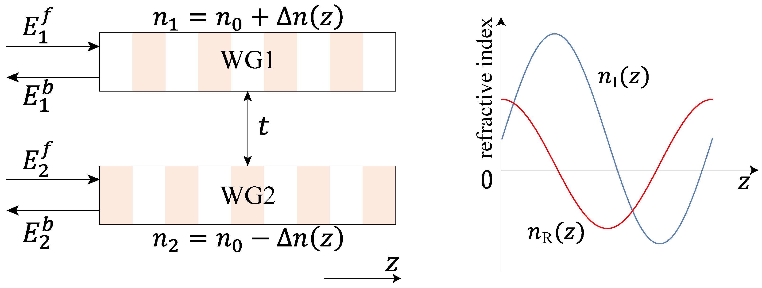
We form a waveguide array using two waveguides as described in Section 2.1, arranged in parallel as shown in Figure 2. In order to distinguish between the two waveguides, the top waveguide is named WG1 and the bottom waveguide is named WG2. Meanwhile, we define E 1 f ( z ) and E 1 b ( z ) as the forward and backward propagation modes for WG1, while E 2 f ( z ) and E 2 b ( z ) as the forward and backward propagation modes for WG2. For WGj ( j = 1 , 2 ), the refractive index n j ( z ) = n 0 + Δ n j ( z ) for 0 < z < L and n j ( z ) = n 0 for z < 0 and z > L . To generate more types of EPs, we have chosen a refractive index modulation scheme with odd symmetry in the waveguide arrangement direction, i.e., Δ n 1 ( z ) = Δ n 2 ( z ) = Δ n ( z ) , this modulation scheme will cause the two waveguides to have gain and loss, respectively, which may lead to gain in the total energy output of the system. There is coupling between two waveguides with a coupling coefficient t, and the coupling only occurs between the same propagation modes. The rest of the settings are the same as those of Section 2.1.
Using the same approach as Section 2.1, we can obtain the Hamiltonian in the waveguide array. The coupled-mode equation in the waveguide array can be written as
d d z Ψ = i H d Ψ ,
here Ψ = [ E 1 f ( z ) , E 1 b ( z ) , E 2 f ( z ) , E 2 b ( z ) ] T and the Hamiltonian is
H d = C 0 σ z σ z C q C q 2 σ z σ x + t σ x I i C q + C q 2 σ z σ y ,
here, ⊗ denotes the direct product, I is the identity matrix, and the other parameters are the same as those in Equation (4). From this, we can obtain the eigenvalues of the Hamiltonian of the system:
λ H = ± a ,
where a = C 0 2 + t 2 C q C q .
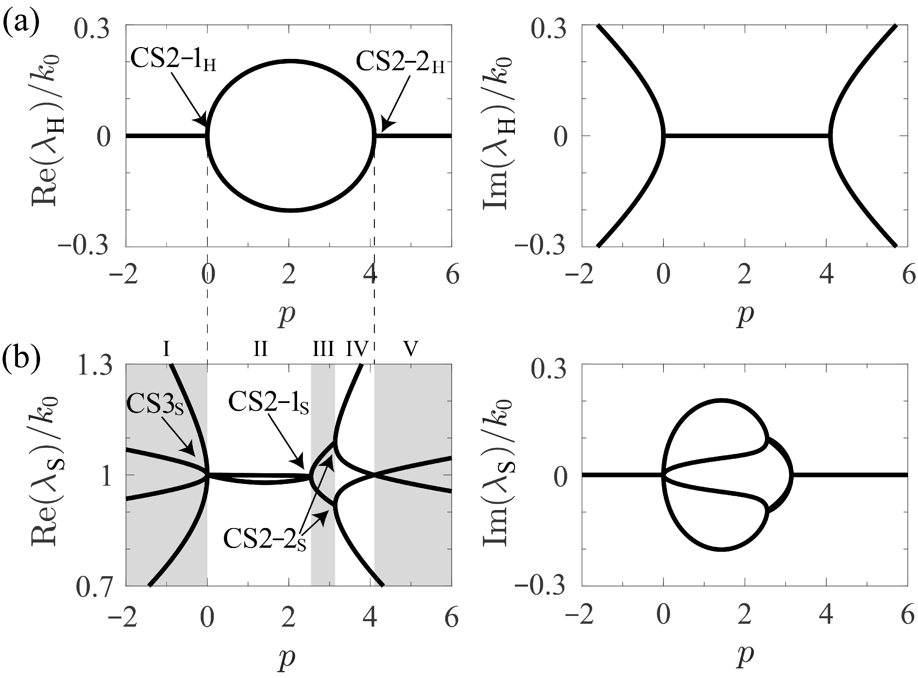
Here, two of the four eigenvalues of the Hamiltonian are exactly the same, and the other two are also exactly the same. There are two EPs in the Hamiltonian when a = 0 , and there are two conditions in which coalescence of states (CSs) occur, respectively, named CS2-1 H that C 0 2 + t 2 = C q C q = 0 and CS2-2 H that C 0 2 + t 2 = C q C q 0 , as shown in Figure 3a. In these two situations, there are two different EPs, each featuring a single defective state. By choosing appropriate refractive index modulation and changing parameters, we can observe the appearance and disappearance of these kinds of EPs. For CS2-1 H , where p = 0 , the real parts of the eigenvalues split and the imaginary parts degenerate as p increases. For CS2-2 H , where p = 8 π / ( 16 π 2 ) , the real parts of the eigenvalues degenerate and the imaginary parts split as p increases. In reality, the change in the real part of the eigenvalue of the Hamiltonian only affects the phase of the wave. In experiments, people are often more interested in the change in the imaginary part that affects the intensity. When the imaginary part is greater than zero, it shows a gain to the system; otherwise, it is a loss. In an optical resonator, as the imaginary part of the eigenvalue splits, the system output increases [9].
Then we derive the scattering matrix of the system to obtain the EPs of the scattering matrix. The transmission matrix of the system is T ( z ) = e i H d z . We defined the vector of the wave, which is located at the left side of the array ( z = 0 ) as E 0 , i.e., E 0 = [ E 1 f ( 0 ) , E 1 b ( 0 ) , E 2 f ( 0 ) , E 2 b ( 0 ) ] T . Meanwhile, we defined the vector of the wave which located at the right side of the array ( z = L ) as E L , i.e., E L = [ E 1 f ( L ) , E 1 b ( L ) , E 2 f ( L ) , E 2 b ( L ) ] T . So the transmission matrix of the system from z = 0 to z = L satisfies
E L = T ( L ) E 0 .
Due to H d 2 = λ H 2 I , the transmission matrix can be written as T = cos ( a L ) I i H d α , where α = sin ( a L ) / a . The corresponding scattering matrix satisfies
E out = S E in ,
where the outgoing vector E out = [ E 1 f ( L ) , E 1 b ( 0 ) , E 2 f ( L ) , E 2 b ( 0 ) ] T , and the incoming vector E in = [ E 1 f ( 0 ) , E 1 b ( L ) , E 2 f ( 0 ) , E 2 b ( L ) ] T . By combining Equations (15) and (16), we can obtain the concrete form of the scattering matrix of the system:
S = 1 b f d 2 S n = 1 b f d 2 b b c d c d b e b d e d d c d f c f d e d e f f ,
where b = cos ( a L ) + i C 0 α , c = i C q α , d = i t α , e = i C q α , f = cos ( a L ) i C 0 α . Then the eigenvalues of the scattering matrix are
λ S , 1 = 1 + i C q C q α cos ( a L ) i C 0 2 + t 2 α , λ S , 2 = 1 i C q C q α cos ( a L ) i C 0 2 + t 2 α , λ S , 3 = 1 + i C q C q α cos ( a L ) + i C 0 2 + t 2 α , λ S , 4 = 1 i C q C q α cos ( a L ) + i C 0 2 + t 2 α .
Similar to Hamiltonian, there are three conditions in which CSs occur, respectively, named CS 3 S that a = 0 and C q C q = 0 , CS2-1 S that a 0 and C q C q = 0 , CS2-2 S that a 0 and C 0 2 + t 2 = 0 , as shown in Figure 3b. At p = 0 , as p increases, the imaginary parts of the eigenvalues split from one value to four different values, and the real parts of the eigenvalues degenerate from four values to one value. At the moment, the system is in CS 3 S , indicating the coalescence of four states, among which three are defective. In addition, this is the same as CS2-1 H . At p = 8 / π , as p increases, the imaginary parts of the eigenvalues degenerate from four values to two values, the real parts of the eigenvalues degenerate from two values to one value, and the system is in CS2-1 S . At p = π , as p increases, the imaginary parts of the eigenvalues degenerate from four values to one value, and the real parts of the eigenvalues split from two values to four values. The system is in CS2-2 S at this point.
As the coupling coefficient, when t / | C ± q | 0 , the system degenerates into two independent single-waveguides, and the phenomena of each waveguide have already been studied in the past [37,41]. When t / | C ± q | , it is equivalent to the other parameters in the Hamiltonian tending towards zero, and according to Equation (17), the system will not exhibit a reflection phenomenon.
The parameters of this work are shown in Table 1.

3. Light Transmission

In this section, we will generate different EPs by adjusting the parameter p and investigate the optical transmission phenomena across different parameter spaces. Based on the four EPs identified in Section 2 through Hamiltonian and scattering matrix eigenvalue analysis, Section 3.1, Section 3.2, Section 3.3 and Section 3.4 characterize unique optical phenomena at each EP. Section 3.5 subsequently contrasts these results by demonstrating transmission behavior when deviating from these EPs.

3.1. CS2-1H (CS3S)

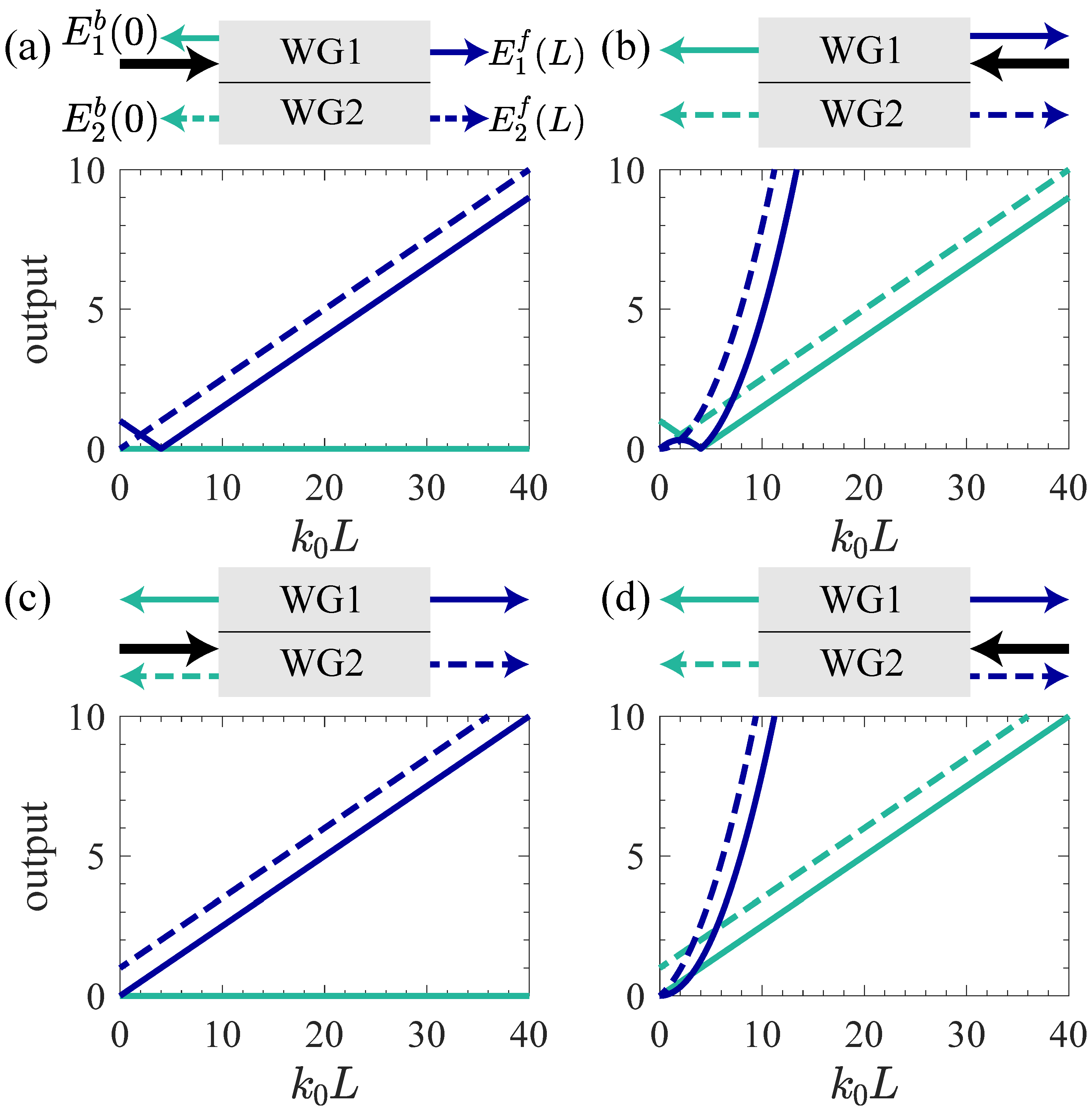
When we modulate the parameters of the refractive index that make the system locate at CS2-1 H ( CS 3 S ), unidirectional transparency will occur in the system, as shown in Figure 4. In this moment, b f d 2 = 1 , then the scattering matrix is
S = 1 + i C 0 L i C q L C 0 C q L 2 i t L t C q L 2 0 1 + i C 0 L 0 i t L i t L t C q L 2 1 i C 0 L i C q L C 0 C q L 2 0 i t L 0 1 i C 0 L .
As shown in Figure 4a, when we give the system an input E in = [ 1 , 0 , 0 , 0 ] T , the outputs of the system varies with the waveguide length L. When the wave enters from the left side of WG1, the entire wave will be transmitted, and there will be no reflected light. As the waveguide length increases, the wave emitted from the right side of WG1 will first decrease and then increase (blue solid line), while the wave emitted from the right side of WG2 will continue to increase (blue dashed line). Equation (19) also shows that the outputs on the right side of the system are linear functions of L. At this time, the total energy of the outgoing wave is ε = | 1 + i C 0 L | 2 + | t L | 2 . This means that the total energy output of the system is proportional to L 2 when L .
Then, as shown in Figure 4b, when we give the system an input E in = [ 0 , 1 , 0 , 0 ] T , the outputs of the system varies with the waveguide length L. When the wave enters from the right side of WG1, there will be outputs in all four directions, unlike the condition that is incident from the left side. As the waveguide length increases, the outputs on the left side of the system are a linear function of L, and the outputs on the right side of the system are a quadratic function of L, as shown in Equation (19). The wave emitted from the right side of WG1 first increases, then decreases to 0, and finally increases to infinity (blue solid line). The wave emitted from the left side of WG1 will first decrease and then increase (green solid line). The wave emitted from both sides of WG2 will continue to increase (dashed line). At this time, the total energy of the outgoing wave is ε = | i C q L C 0 C q L 2 | 2 + | 1 + i C 0 L | 2 + | t C q L 2 | + | t L | 2 . This means that the total energy output of the system is proportional to L 4 when L .
As shown in Figure 4c,d, when we give the system inputs E in = [ 0 , 0 , 1 , 0 ] T and E in = [ 0 , 0 , 0 , 1 ] T , the outputs of the system varies with the waveguide length L. When a wave is incident on both sides of WG2, its output is similar to that of WG1, but the difference is that the outgoing amplitude will continue to increase with the increase of waveguide length without decreasing. Equation (19) also shows the similarity between the outputs when the wave is incident from WG2 and when it is incident from WG1. For Figure 4c, the total energy of the outgoing wave is ε c = | t L | 2 + | 1 i C 0 L | 2 and this is proportional to L 2 when L . For Figure 4d, the total energy is ε d = | t C q L 2 | 2 + | t L | 2 + | i C q L + C 0 C q L 2 | 2 + | 1 i C 0 L | 2 and this is proportional to L 4 when L .
In summary, at CS2-1 H ( CS 3 S ), irrespective of the input, the system’s incoming wave is transmitted, with the transmitted wave linearly varying with the waveguide length. However, the incoming wave incident from WG1 initially couples to WG2 during transmission, causing the transmitted wave from WG1 to first decrease and then increase, whereas the wave incident from WG2 directly transmits and linearly escalates. Concurrently, due to the coupling effect between waveguides, whether it is the transmitted wave or the reflected wave, the outgoing wave of WG2 is more intense than that of WG1.

3.2. CS2-1S

Then, when we modulate the parameters of the refractive index that make the system locate at CS2-1 S , periodic transmission occurs, as shown in Figure 5. In this moment, b f d 2 = 1 , then the scattering matrix is
S = b 0 d 0 b e b d e d d 0 f 0 d e d e f f .
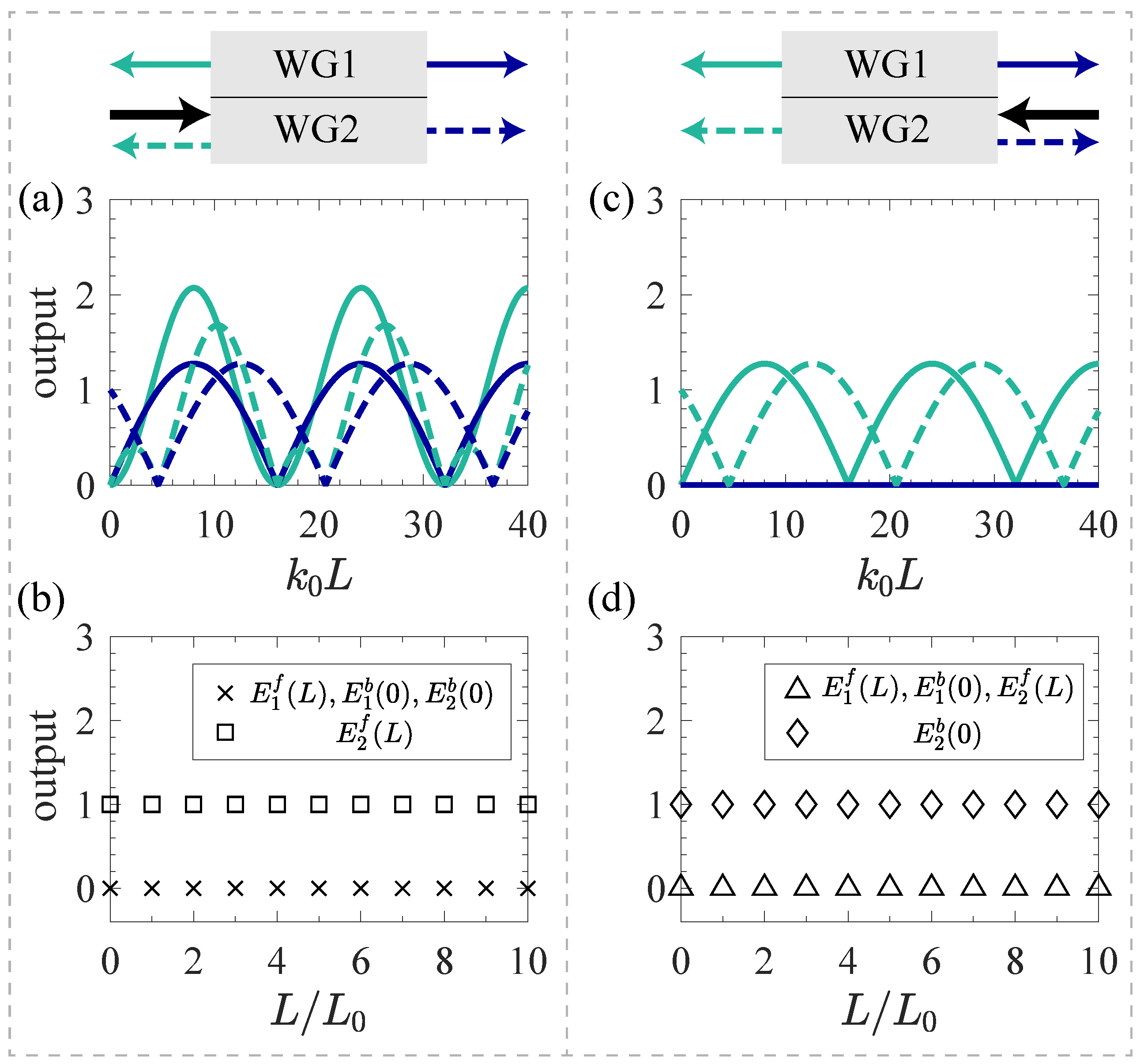
As shown in Figure 5a,b, when we give the system an input E in = [ 0 , 0 , 1 , 0 ] T , the outputs of the system vary with the waveguide length L. When the wave enters from the left side of WG2, the outgoing amplitude changes periodically with the length of the waveguide L, and as shown in Equation (20), the variation period is L 0 = π / a . At the same time, if the waveguide length is changed equidistantly from 0 with a spacing of L 0 , it can be observed that the wave will be transmitted from the right side of WG2, as shown in Figure 5b. At this time, the total energy of the outgoing wave is ε = | d ( L ) | 2 + | d ( L ) e ( L ) | 2 + | f ( L ) | 2 + | e ( L ) f ( L ) | 2 , which is a periodic function with a period of L 0 . Therefore, the total energy output will oscillate periodically as the length of the waveguide increases.
Then, as shown in Figure 5c,d, when we give the system an input E in = [ 0 , 0 , 0 , 1 ] T , the outputs of the system vary with the waveguide length L. The wave that is incident from the right side of the system will be transmitted without reflection, which can also be seen from Equation (20). If the waveguide length is changed equidistantly from 0 with a spacing of L 0 , it can be observed that all incident waves will be transmitted from the other side of the incident waveguide, without reflection or emission from both sides of the other waveguide through coupling, as shown in Figure 5d. At this time, the total energy of the outgoing wave is ε = | d ( L ) | 2 + | f ( L ) | 2 , which is also a periodic function with a period of L 0 . So the total energy output is similar to before and shows periodic oscillate.
In summary, at CS2-1 S , as the waveguide length increases, the outgoing wave amplitude periodically changes with a period of L 0 . At the same time, if the wave is incident from the right side of the system, it will not be reflected.

3.3. CS2-2S

When we modulate the parameters of the refractive index that make the system locates at CS2-2 S , we will observe that the output of wave changes periodically that is similar to the system at CS2-1 S , as shown in Figure 6. In this moment, b f d 2 = cos 2 ( a L ) , then the scattering matrix is
S = S n cos 2 ( a L ) ,
here S n is defined in Equation (17).
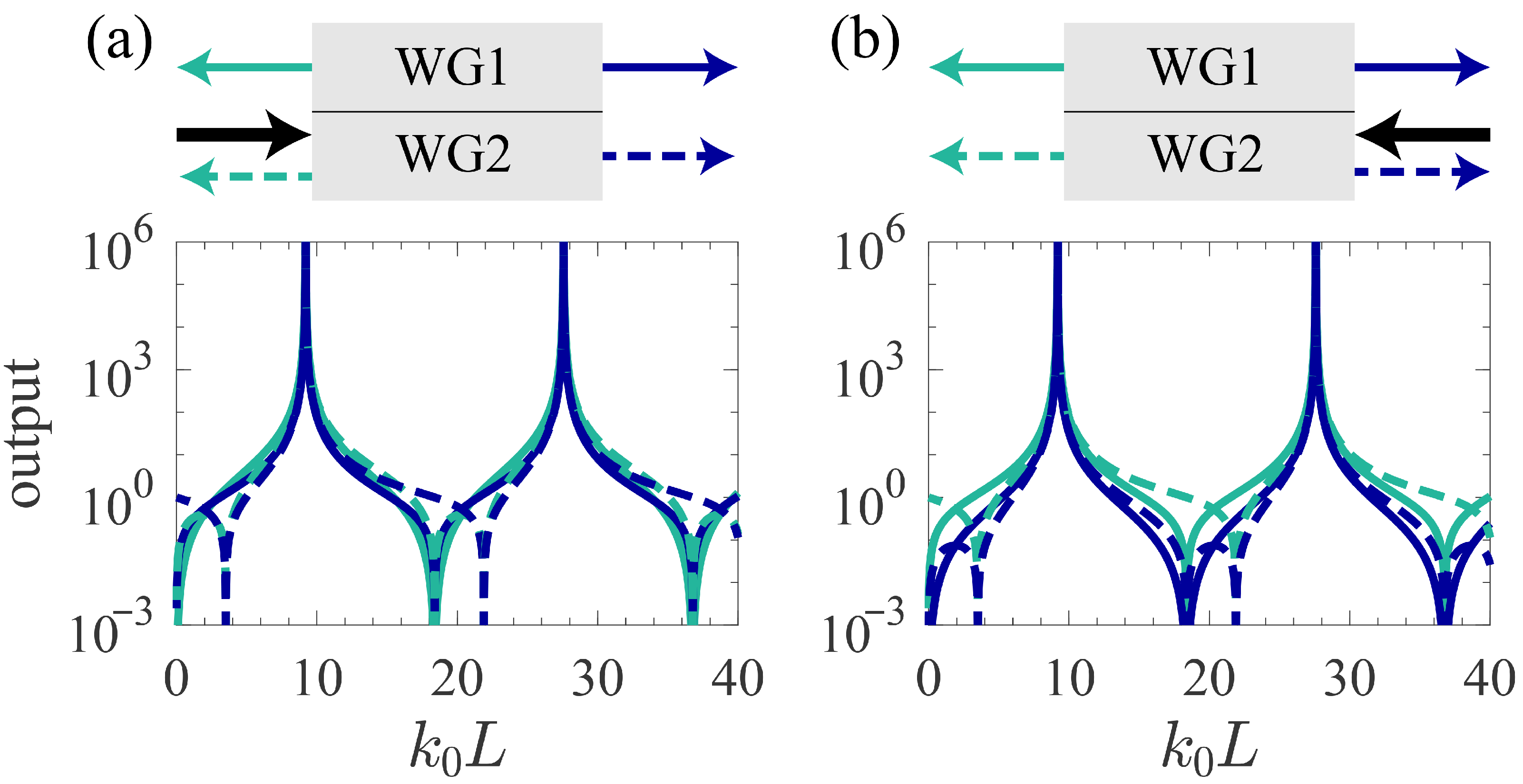
As shown in Figure 6, When we give the system inputs E in = [ 0 , 0 , 1 , 0 ] T and E in = [ 0 , 0 , 0 , 1 ] T , the outgoing wave will appear in all four exit directions, and the amplitude will periodically change with the increase of waveguide length L, with divergent points tending towards infinity appearing in each period. In this case, as shown in Equation (21), there is no significant difference in the outputs corresponding to the four different inputs. In addition, each element in Equation (21) is a periodic function with respect to the waveguide length L, with a period of L 0 . Meanwhile, due to the common factor of the scattering matrix related to L, the output will rapidly increase to infinity when a L = π / 2 + n π (here n is a natural number). This divergence point arises because we are considering an ideal system where the gain does not decrease as the electric field increases. However, in real systems, external energy input is finite, and the electric field cannot increase indefinitely. Therefore, real physical systems do not exhibit divergence points. In addition, at this EP, the total energy of the outgoing wave is ε a = [ | d ( L ) | 2 + | d ( L ) e ( L ) | 2 + | f ( L ) | 2 + | e ( L ) f ( L ) | 2 ] / cos 4 ( a L ) for Figure 6a and ε b = [ | c ( L ) d ( L ) | 2 + | d ( L ) | 2 + | c ( L ) f ( L ) | 2 + | f ( L ) | 2 ] / cos 4 ( a L ) for Figure 6b. Here, both ε a and ε b are periodic functions with a period of L 0 , causing periodic oscillations. In an ideal system, the total energy output will rapidly increase to infinity when a L = π / 2 + n π .
In summary, at CS2-2 S , as the waveguide length increases, the amplitude of the outgoing wave periodically changes, with a period of L 0 . At the same time, when the waveguide length satisfies a L = π / 2 + n π , the outgoing amplitude tends to infinity, and divergence points appear in this situation.

3.4. CS2-2H)

Subsequently, we modulate the parameters of the refractive index to position that making the system at CS2-2 H . In this moment, b f d 2 = 1 + ( C 0 2 + t 2 ) L 2 , then the scattering matrix is
S = S n 1 + ( C 0 2 + t 2 ) L 2 ,
here S n is defined in Equation (17).
Unlike the previous three situations, in this situation, the scattering matrix of the system does not exhibit degeneracy of the eigenvalues and eigenstates, but is replaced by the degeneracy of the Hamiltonian.
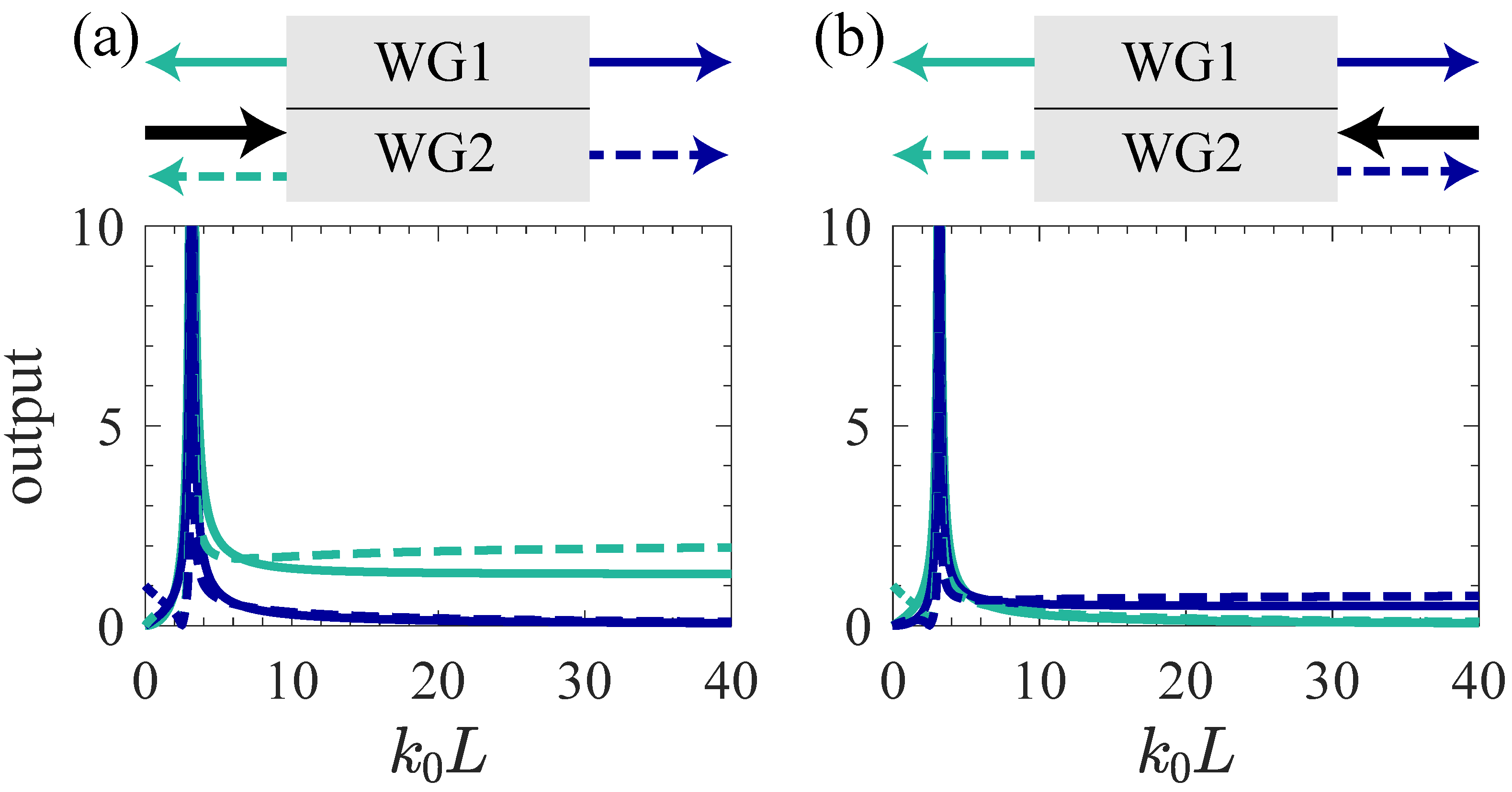
As shown in Figure 7, when we give the system inputs E in = [ 0 , 0 , 1 , 0 ] T and E in = [ 0 , 0 , 0 , 1 ] T , regardless of the direction in which the wave enters the system, as the waveguide length increases, the outgoing amplitude will first pass through a divergent point that tends towards infinity and then tend towards a finite value. At this time, the total energy of the outgoing wave is ε a = [ | d ( L ) | 2 + | d ( L ) e ( L ) | 2 + | f ( L ) | 2 + | e ( L ) f ( L ) | 2 ] / [ 1 + ( C 0 2 + t 2 ) L 2 ] 2 for Figure 7a and ε b = [ | c ( L ) d ( L ) | 2 + | d ( L ) | 2 + | c ( L ) f ( L ) | 2 + | f ( L ) | 2 ] / [ 1 + ( C 0 2 + t 2 ) L 2 ] 2 for Figure 7b.
Unlike CS2-1 S and CS2-2 S , each element in Equation (22) is no longer a periodic function of the waveguide length L, so the outgoing amplitude as the waveguide length changes does not have the characteristic of periodic variation in Figure 7. Similar to CS2-2 S , due to the common factor of the scattering matrix related to L, when 1 + ( C 0 2 + t 2 ) L 2 = 0 , the outgoing amplitude and total energy output will rapidly increase to infinity in an ideal system. When the waveguide length L , by calculating the limits of each element in the matrix, it can be found that
lim L S = 1 C 0 2 + t 2 0 C 0 C q 0 t C q C 0 C q 0 t C q 0 0 t C q 0 C 0 C q t C q 0 C 0 C q 0 .
These calculation results are the contribution of the wave that is incident from different directions to the four outgoing amplitudes. This means that for an infinitely long waveguide array, the incoming wave with stable amplitude will all reflect, and there will also be a wave reflected from another waveguide under the coupling effect between waveguides. For the waves that enter from the left side of the waveguide, the total energy output is ε left = ( | C 0 C q | 2 + | t C q | 2 ) / ( C 0 2 + t 2 ) 2 , while for the waves that enter from the right side of the waveguide, the total energy output is ε right = ( | C 0 C q | 2 + | t C q | 2 ) / ( C 0 2 + t 2 ) 2 .
In summary, at CS2-2 H , as the waveguide length increases, the system will pass through a divergent point where the waveguide length satisfies 1 + ( C 0 2 + t 2 ) L 2 = 0 . As the length continues to increase beyond this point, the outgoing amplitude will rapidly decrease and gradually approach finite values independent of the waveguide length.

3.5. Out of EPs

Finally, we modulate the refractive index parameter so that the system is no longer in any of the four positions mentioned above, and observe the variation of the outgoing amplitude with the length of the waveguide when the system is in one of the regions that are divided by these four positions.
The five regions divided by these positions is shown in Figure 8a, and then we select one position from every region to observe the variation of the outgoing amplitude with the length of the waveguide when we give the system an input E in = [ 0 , 0 , 1 , 0 ] T .
The positions at I and V are located on both sides of the two CSs of the Hamiltonian, i.e., p < 0 and p > 8 π / ( 16 π 2 ) , respectively. As shown in Figure 8b,f, we can observe that the curve trend is similar to the variation at CS2-2 H , first passing through a divergent point, and then decreasing rapidly and tending towards a finite value when L . As shown in Figure 8c–e, when the system is in II, III, and IV, the outgoing amplitude exhibits a periodic variation with the length of the waveguide, and these three positions are located between the two CSs of the Hamiltonian. The position at II is between CS2-1 H ( CS 3 S ) and CS2-1 S , the position at III is between CS2-1 S and CS2-2 S , and the position at IV is between CS2-2 S and CS2-2 H . Compared to II, the system at III has a higher gain, which will bring more energy to the wave. For IV, unlike the other two, there will be two divergent points in each period. At this time, the total energy of the outgoing wave for these regions is ε = [ | d ( L ) | 2 + | d ( L ) e ( L ) | 2 + | f ( L ) | 2 + | e ( L ) f ( L ) | 2 ] / [ b ( L ) f ( L ) d 2 ( L ) ] 2 . For I and V, the total energy output will rapidly increase and then tend to a value. For II, III, and IV, the total energy output will oscillate periodically, and for IV, in addition to this, there will also be periodic divergent responses.
In summary, we modulate the refractive index of the system to positions that place the system in regions I–V and observed the output at these regions. The phenomena are shown in Table 2. When the refractive index of the system is modulated between CS2-1 H ( CS 3 S ) and CS2-2 H , the outgoing amplitude will periodically change with the increase of waveguide length. When the refractive index of the system is modulated to both sides of CS2-1 H ( CS 3 S ) and CS2-2 S , the outgoing amplitude will diverge when the waveguide length satisfies b f d 2 = 0 . When the refractive index of the waveguide is modulated to both sides of CS2-1 H ( CS 3 S ) and CS2-2 H , and the length of the waveguide tends towards infinity, the outgoing amplitude tends to finite values.

4. Conclusions

In summary, this study has presented a comprehensive investigation into the behavior of a double-waveguide system under various EPs, revealing the complex interplay between non-Hermitian physics and optical transmission. Our findings underscore the profound impact of EPs on the scattering and transmission characteristics of waveguides. At CS2-1 H ( CS 3 S ), we observed unidirectional transparency and amplification, highlighting the potential for novel optical devices that exploit these properties. The periodic transmission observed at CS2-1 S and CS2-2 S has implications for the design of optical switches and modulators, where precise control over wave propagation is paramount. Furthermore, the divergence phenomena at CS2-2 H and in regions beyond the EPs have shed light on the limits of transmission and the conditions for instability in these systems.
The model discussed in this paper is experimentally feasible. Based on the experimental scheme described in Ref. [37], we can achieve the modulated refractive index proposed herein by separately modulating the real and imaginary parts of the refractive index in silicon-based waveguides. Then, the waveguides are coupled via evanescent waves to realize the model discussed in this paper. Although we have made some approximations and simplifications in the article, this will not affect the occurrence of physical phenomena. In subsequent research, we can explore the optical transmission characteristics under different conditions by expanding the waveguide array or introducing nonlinearity.

Author Contributions

Conceptualization, Y.S. and Y.H.; methodology, Y.Y. and Y.S.; software, Y.Y. and Z.W.; validation, Z.W.; formal analysis, Y.Y., Z.W. and Y.S.; investigation, Y.Y. and Z.W.; data curation, Z.W.; writing—original draft preparation, Z.W.; writing—review and editing, Y.Y. and Z.W.; visualization, Z.W. All authors have read and agreed to the published version of the manuscript.

Funding

This research is funded by the National Natural Science Foundation of China (Grants No. 12374246). Y.H. acknowledges support by Beijing National Laboratory for Condensed Matter Physics (No. 2023BNLCMPKF001).

Data Availability Statement

The datasets used and/or analyzed during the current study are available from the corresponding author on reasonable request.

Conflicts of Interest

The author declares no conflicts of interest.

References

  1. Heiss, W.D. Repulsion of Resonance States and Exceptional Points. Phys. Rev. E 2000, 61, 929–932. [Google Scholar] [CrossRef] [PubMed]
  2. Heiss, W.D. The Physics of Exceptional Points. J. Phys. A Math. Theor. 2012, 45, 444016. [Google Scholar] [CrossRef]
  3. Ashida, Y.; Gong, Z.; Ueda, M. Non-Hermitian Physics. Adv. Phys. 2020, 69, 249–435. [Google Scholar] [CrossRef]
  4. Bergholtz, E.J.; Budich, J.C.; Kunst, F.K. Exceptional Topology of Non-Hermitian Systems. Rev. Mod. Phys. 2021, 93, 015005. [Google Scholar] [CrossRef]
  5. Ding, K.; Fang, C.; Ma, G. Non-Hermitian Topology and Exceptional-point Geometries. Nat. Rev. Phys. 2022, 4, 745–760. [Google Scholar] [CrossRef]
  6. Ding, K.; Ma, G.; Xiao, M.; Zhang, Z.Q.; Chan, C.T. Emergence, Coalescence, and Topological Properties of Multiple Exceptional Points and Their Experimental Realization. Phys. Rev. X 2016, 6, 021007. [Google Scholar] [CrossRef]
  7. Ding, K.; Zhang, Z.Q.; Chan, C.T. Coalescence of Exceptional Points and Phase Diagrams for One-dimensional PT-symmetric Photonic Crystals. Phys. Rev. B 2015, 92, 235310. [Google Scholar] [CrossRef]
  8. San-Jose, P.; Cayao, J.; Prada, E.; Aguado, R. Majorana Bound States from Exceptional Points in Non-topological Superconductors. Sci. Rep. 2016, 6, 21427. [Google Scholar] [CrossRef]
  9. Peng, B.; Özdemir, K.; Rotter, S.; Yilmaz, H.; Liertzer, M.; Monifi, F.; Bender, C.M.; Nori, F.; Yang, L. Loss-Induced Suppression and Revival of Lasing. Science 2014, 346, 328–332. [Google Scholar] [CrossRef]
  10. Wang, K.; Xiao, L.; Lin, H.; Yi, W.; Bergholtz, E.J.; Xue, P. Experimental Simulation of Symmetry-protected Higher-order Exceptional Points with Single Photons. Sci. Adv. 2023, 9, eadi0732. [Google Scholar] [CrossRef] [PubMed]
  11. Arkhipov, I.I.; Miranowicz, A.; Minganti, F.; Özdemir, K.; Nori, F. Dynamically Crossing Diabolic Points while Encircling Exceptional Curves: A Programmable Symmetric-Asymmetric Multimode Switch. Nat. Commun. 2023, 14, 2076. [Google Scholar] [CrossRef]
  12. Dembowski, C.; Gräf, H.D.; Harney, H.L.; Heine, A.; Heiss, W.D.; Rehfeld, H.; Richter, A. Experimental Observation of the Topological Structure of Exceptional Points. Phys. Rev. Lett. 2001, 86, 787–790. [Google Scholar] [CrossRef]
  13. Sayyad, S.; Kunst, F.K. Realizing Exceptional Points of any Order in the Presence of Symmetry. Phys. Rev. Res. 2022, 4, 023130. [Google Scholar] [CrossRef]
  14. Eleuch, H.; Rotter, I. Open Quantum Systems and Dicke Superradiance. Eur. Phys. J. D 2014, 68, 74. [Google Scholar] [CrossRef]
  15. Peng, P.; Cao, W.; Shen, C.; Qu, W.; Wen, J.; Jiang, L.; Xiao, Y. Anti-parity–time Symmetry with Flying Atoms. Nat. Phys. 2016, 12, 1139–1145. [Google Scholar] [CrossRef]
  16. Li, J.; Harter, A.K.; Liu, J.; de Melo, L.; Joglekar, Y.N.; Luo, L. Observation of Parity-time Symmetry Breaking Transitions in a Dissipative Floquet System of Ultracold Atoms. Nat. Commun. 2019, 10, 855. [Google Scholar] [CrossRef] [PubMed]
  17. Ren, Z.; Liu, D.; Zhao, E.; He, C.; Pak, K.K.; Li, J.; Jo, G.B. Chiral Control of Quantum States in Non-Hermitian Spin–orbit-coupled Fermions. Nat. Phys. 2022, 18, 385–389. [Google Scholar] [CrossRef]
  18. Liang, C.; Tang, Y.; Xu, A.N.; Liu, Y.C. Observation of Exceptional Points in Thermal Atomic Ensembles. Phys. Rev. Lett. 2023, 130, 263601. [Google Scholar] [CrossRef]
  19. Ding, L.; Shi, K.; Zhang, Q.; Shen, D.; Zhang, X.; Zhang, W. Experimental Determination of PT-symmetric Exceptional Points in a Single Trapped Ion. Phys. Rev. Lett. 2021, 126, 083604. [Google Scholar] [CrossRef] [PubMed]
  20. Wu, Y.; Liu, W.; Geng, J.; Song, X.; Ye, X.; Duan, C.K.; Rong, X.; Du, J. Observation of Parity-time symmetry Breaking in a Single-spin System. Science 2019, 364, 878–880. [Google Scholar] [CrossRef]
  21. Choi, Y.; Kang, S.; Lim, S.; Kim, W.; Kim, J.R.; Lee, J.H.; An, K. Quasieigenstate Coalescence in an Atom-cavity Quantum Composite. Phys. Rev. Lett. 2010, 104, 153601. [Google Scholar] [CrossRef] [PubMed]
  22. Bender, C.M.; Boettcher, S. Real Spectra in Non-Hermitian Hamiltonians Having PT Symmetry. Phys. Rev. Lett. 1998, 80, 5243–5246. [Google Scholar] [CrossRef]
  23. Ruschhaupt, A.; Delgado, F.; Muga, J.G. Physical Realization of PT-symmetric Potential Scattering in a Planar Slab Waveguide. J. Phys. A Math. Gen. 2005, 38, L171. [Google Scholar] [CrossRef]
  24. El-Ganainy, R.; Makris, K.G.; Christodoulides, D.N.; Musslimani, Z.H. Theory of Coupled Optical PT-symmetric Structures. Opt. Lett. 2007, 32, 2632–2634. [Google Scholar] [CrossRef]
  25. Guo, A.; Salamo, G.J.; Duchesne, D.; Morandotti, R.; Volatier-Ravat, M.; Aimez, V.; Siviloglou, G.A.; Christodoulides, D.N. Observation of PT-symmetry Breaking in Complex Optical Potentials. Phys. Rev. Lett. 2009, 103, 093902. [Google Scholar] [CrossRef]
  26. Rüter, C.E.; Makris, K.G.; El-Ganainy, R.; Christodoulides, D.N.; Segev, M.; Kip, D. Observation of Parity-time Symmetry in Optics. Nat. Phys. 2010, 6, 192–195. [Google Scholar] [CrossRef]
  27. Feng, L.; Ayache, M.; Huang, J.; Xu, Y.L.; Lu, M.H.; Chen, Y.F.; Fainman, Y.; Scherer, A. Nonreciprocal Light Propagation in a Silicon Photonic Circuit. Science 2011, 333, 729–733. [Google Scholar] [CrossRef] [PubMed]
  28. Feng, L.; El-Ganainy, R.; Ge, L. Non-Hermitian Photonics Based on Parity–time Symmetry. Nat. Photonics 2017, 11, 752–762. [Google Scholar] [CrossRef]
  29. Bender, N.; Factor, S.; Bodyfelt, J.D.; Ramezani, H.; Christodoulides, D.N.; Ellis, F.M.; Kottos, T. Observation of Asymmetric Transport in Structures with Active Nonlinearities. Phys. Rev. Lett. 2013, 110, 234101. [Google Scholar] [CrossRef]
  30. Chen, Z.; Wang, H.; Luo, B.; Guo, H. Parity-time Symmetric Bragg Structure in Atomic Vapor. Opt. Express 2014, 22, 25120–25127. [Google Scholar] [CrossRef]
  31. Zhu, X.; Ramezani, H.; Shi, C.; Zhu, J.; Zhang, X. PT-symmetric Acoustics. Phys. Rev. X 2014, 4, 031042. [Google Scholar] [CrossRef]
  32. Feng, L.; Wong, Z.J.; Ma, R.M.; Wang, Y.; Zhang, X. Single-mode Laser by Parity-time Symmetry Breaking. Science 2014, 346, 972–975. [Google Scholar] [CrossRef]
  33. Peng, B.; Özdemir, K.; Lei, F.; Monifi, F.; Gianfreda, M.; Long, G.L.; Fan, S.; Nori, F.; Bender, C.M.; Yang, L. Parity–time-symmetric Whispering-gallery Microcavities. Nat. Phys. 2014, 10, 394–398. [Google Scholar] [CrossRef]
  34. Nazari, F.; Abdollahi, S.; Samsami-Khodadad, F. On-chip Magnetic-free Optical Multi-port Circulator Based on a Locally Linear Parity-time Symmetric System. Appl. Opt. 2019, 58, 2867–2872. [Google Scholar] [CrossRef] [PubMed]
  35. Hodaei, H.; Miri, M.A.; Heinrich, M.; Christodoulides, D.N.; Khajavikhan, M. Parity-time–symmetric Microring Lasers. Science 2014, 346, 975–978. [Google Scholar] [CrossRef] [PubMed]
  36. Kang, M.; Liu, F.; Li, J. Effective Spontaneous PT-symmetry Breaking in Hybridized Metamaterials. Phys. Rev. A 2013, 87, 053824. [Google Scholar] [CrossRef]
  37. Feng, L.; Xu, Y.L.; Fegadolli, W.S.; Lu, M.H.; Oliveira, J.E.B.; Almeida, V.R.; Chen, Y.F.; Scherer, A. Experimental Demonstration of a Unidirectional Reflectionless Parity-time Metamaterial at Optical Frequencies. Nat. Mater. 2013, 12, 108–113. [Google Scholar] [CrossRef]
  38. Lee, J.Y.; Chen, P.Y. Generalized Parametric Space, Parity Symmetry of Reflection, and Systematic Design Approach for Parity-time-symmetric Photonic Systems. Phys. Rev. A 2021, 104, 033510. [Google Scholar] [CrossRef]
  39. Boucher, Y.G.; Féron, P. Parity-time Symmetry in Laterally Coupled Bragg Waveguides. IEEE J. Quantum Electron. 2019, 55, 1–9. [Google Scholar] [CrossRef]
  40. Shu, X.; Zhong, Q.; Hong, K.; You, O.; Wang, J.; Hu, G.; Alù, A.; Zhang, S.; Christodoulides, D.N.; Chen, L. Chiral Transmission by an Open Evolution Trajectory in a Non-Hermitian System. Light Sci. Appl. 2024, 13, 65. [Google Scholar] [CrossRef]
  41. Lin, Z.; Ramezani, H.; Eichelkraut, T.; Kottos, T.; Cao, H.; Christodoulides, D.N. Unidirectional Invisibility Induced by PT-symmetric Periodic Structures. Phys. Rev. Lett. 2011, 106, 213901. [Google Scholar] [CrossRef] [PubMed]
  42. Novitsky, A.; Lyakhov, D.; Michels, D.; Pavlov, A.A.; Shalin, A.S.; Novitsky, D.V. Unambiguous Scattering Matrix for Non-Hermitian Systems. Phys. Rev. A 2020, 101, 043834. [Google Scholar] [CrossRef]
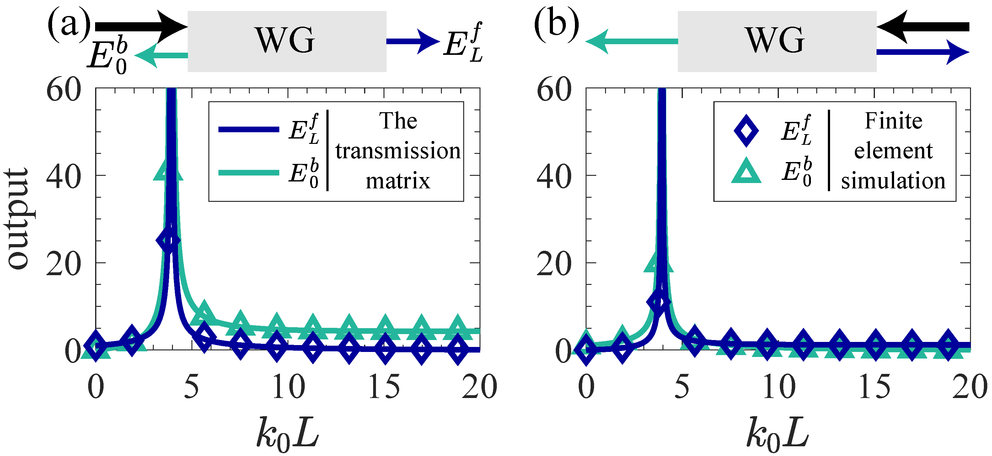
Figure 1. The outgoing amplitudes as a function of waveguide length L, numerically calculated via transmission matrix and finite element simulations, respectively, when the wave is incident from the (a) left and (b) right sides of the waveguide. Here p = 3.5 , m = 4 / π , g = 1 , n 0 = 10 . The blue represents the wave emitted from the right side of the waveguide, while the green represents the wave emitted from the left side. The solid line represents the amplitude calculated via the transmission matrix, while the diamond and triangular denote the amplitude computed through finite element simulation.
Symmetry 17 01748 g001
Figure 2. Schematic of the model of the waveguide array, where the length of every waveguide is L. Each waveguide has two propagation modes, and the coupling rate between the two waveguides is t. The refractive index is periodically distributed in the waveguide. The real part of the modulated refractive index n R ( z ) = m cos ( q z ) , and the imaginary part n I ( z ) = g + p sin ( q z ) [Equation (1)]. For WG1, the modulated refractive index Δ n 1 ( z ) = Δ n ( z ) , while the modulated refractive index Δ n 2 ( z ) = Δ n ( z ) for WG2.
Symmetry 17 01748 g002
Figure 3. The eigenvalue evolution of (a) the Hamiltonian and (b) the scattering matrix of the system as parameter p varies from 2 to 6. The left column represents the real parts of the eigenvalues, and the right column represents the imaginary parts. Here m = 4 / π , g = 1 , t / k 0 = 1 / 4 , k 0 L = 0.5 . In (a), there are two EPs in the Hamiltonian when p = [ 4 π g 4 g 2 ( π 2 8 ) + π 2 ( π 2 16 ) ( m 2 64 t 2 ) ] / ( 16 π 2 ) = 0 and p = [ 4 π g + 4 g 2 ( π 2 8 ) + π 2 ( π 2 16 ) ( m 2 64 t 2 ) ] / ( 16 π 2 ) = 8 π / ( 16 π 2 ) , and we named them CS2-1 H and CS2-2 H , respectively. According to Equation (14), the four eigenvalues coalesce into two degenerate pairs. There are three EPs in the scattering matrix when p = ( g 4 t ) π / 2 = m + 4 g / π = 0 , p = m + 4 g / π = 8 / π and p = ( g + 4 t ) π / 2 = π , and we named them CS 3 S , CS2-1 S and CS2-2 S , respectively. Notably, CS2-1 H and CS 3 S are the same point.
Symmetry 17 01748 g003
Figure 4. Unidirectional transmission and amplification of wave at CS2-1 H ( CS 3 S ), where p = 0 , m = 4 / π , g = 1 , t / k 0 = 1 / 4 . (ad) The variation of the outgoing amplitude with waveguide length L when the wave is incident from (a) the left side of WG1, (b) the right side of WG1, (c) the left side of WG2, and (d) the right side of WG2. Four different lines represent four different types of outgoing amplitude. The blue solid line represents the wave emitted from the right side of WG1, while the green solid line represents the wave emitted from the left side. The blue dashed line represents the wave emitted from the right side of WG2, while the green dashed line represents the wave emitted from the left side.
Symmetry 17 01748 g004
Figure 5. Periodic amplitude oscillations of wave at CS2-1 S , where p = 8 / π , m = 4 / π , g = 1 , t / k 0 = 1 / 4 . (ad) The variation of the outgoing amplitude with waveguide length when light is incident from (a,b) the left side of WG2 and (c,d) the right side of WG2. In (a,c), the waveguide length can vary arbitrarily, while in (b,d), L 0 = π / a , meaning that the waveguide length L changes with the outgoing amplitude period π / a .
Symmetry 17 01748 g005
Figure 6. Divergent responses of wave at CS2-2 S , where p = π , m = 4 / π , g = 1 , t / k 0 = 1 / 4 . (a,b) The variation of the outgoing amplitude with waveguide length L when the wave is incident from (a) the left side of WG2 and (b) the right side of WG2. Regardless of which side the wave is incident from, the outgoing amplitude will periodically change with the increase of waveguide length, and tends towards infinity when a L = π / 2 + n π , where n is a natural number.
Symmetry 17 01748 g006
Figure 7. The transmission of wave at CS2-2 H , where p = 8 π / ( 16 π 2 ) , m = 4 / π , g = 1 , t / k 0 = 1 / 4 . (a,b) The variation of the outgoing amplitude with waveguide length L when the wave is incident from (a) the left side of WG2 and (b) the right side of WG2. It will tend towards infinity when 1 + ( C 0 2 + t 2 ) L 2 = 0 and then tend towards finite values.
Symmetry 17 01748 g007
Figure 8. The transmission of the wave when the system is out of EPs. In this case, the wave is incident from the left side of WG2. (a) Schematic of five regions divided by CSs. (bf) The variation of the outgoing amplitude with waveguide length L when (b) p = 1 , (c) p = 5 / 4 , (d) p = 11 / 4 , (e) p = 7 / 2 and (f) p = 9 / 2 . Here, the other parameters of the modulated refractive index are m = 4 / π , g = 1 , t / k 0 = 1 / 4 .
Symmetry 17 01748 g008
Table 1. The parameters of this work.
E f ( z ) The amplitude of the forward propagating modes
E b ( z ) The amplitude of the backward propagating modes
n ( z ) The refractive index of the waveguide
n 0 The refractive index of the homogeneous medium
Δ n ( z ) The modulated refractive index of the waveguide
q = 2 k A constant used to coupling two modes
k = n 0 k 0 The wave vector in the homogeneous medium
k 0 the wave vector in vacuum
p, g and mThe parameters of modulated refractive index
tThe coupling coefficient between two waveguides
H s Hamiltonian of single waveguide
H d Hamiltonian of double waveguide
C 0 , C q and C q The parameters of Hamiltonian in waveguide system
σ x , σ y and σ z Pauli matrices
IIdentity matrix
TThe transmission matrix
SThe scattering matrix
λ H The eigenvalues of the Hamiltonian matrix
λ S The eigenvalues of the scattering matrix
a, α , b, c, d, e and fThe parameters of the scattering matrix
Table 2. The key behaviors of regions I–V.
RegionKey Behavior
IAppear a divergent point, and then tend towards a finite value when L
IIPeriodic amplitude oscillations
IIIPeriodic amplitude oscillations
IVPeriodic amplitude oscillations and divergent responses
VAppear a divergent point, and then tend towards a finite value when L
Disclaimer/Publisher’s Note: The statements, opinions and data contained in all publications are solely those of the individual author(s) and contributor(s) and not of MDPI and/or the editor(s). MDPI and/or the editor(s) disclaim responsibility for any injury to people or property resulting from any ideas, methods, instructions or products referred to in the content.