Abstract
Hybrid cascaded multi-terminal HVDC systems represent a significant advancement in HVDC transmission technology. A notable real-world implementation of this concept is the bipolar hybrid cascaded multi-terminal high voltage direct current (MTDC) project in China, which successfully transmits hydropower from Baihetan to Jiangsu. This system combines MMCs for system support with LCCs for high-power transmission, offering both flexibility and efficiency in long-distance power delivery. This research explores the characteristics of main DC fault types in such systems, classifying faults based on sections and modes while analyzing their unique outcomes depending on DC fault locations. By focusing on the DC-side terminal behavior of the MMCs and LCCs, the main response processes to asymmetrical DC faults are investigated in detail. This study offers a detailed analysis of asymmetrical DC faults in bipolar HVDC systems, proposing a new classification based on fault characteristics such as current, voltage, active power, and reactive power. A supporting theoretical analysis is also presented. It identifies specific control demands needed for effective fault mitigation. PSCAD/EMTDC simulation results demonstrate that DC faults with similar characteristics can be consistently grouped into distinct categories by this new classification method. Each category is further linked to specific control demands, providing a strong basis for developing advanced protection strategies and practical solutions that enhance the stability and reliability of hybrid cascaded HVDC systems.
1. Introduction
The bipolar hybrid cascaded multi-terminal HVDC topology represents an efficient and practical configuration for large-scale power transmission. In this structure, line-commutated converters (LCCs) are incorporated in series, leveraging their proven capability to transfer bulk power over long distances with minimal losses, as demonstrated in point-to-point HVDC links. Meanwhile, modular multilevel converters (MMCs) are deployed on the inverter side in parallel branches, where their superior controllability, ability to manage reactive power, and suitability for weak grids make them ideal for regional applications such as offshore wind integration. This complementary use of LCC and MMC technologies highlights their distinct roles in modern MTDC projects and underscores the advantages of hybrid cascaded configurations [1]. The primary challenge in high voltage direct current (HVDC) systems lies in rapidly interrupting DC-side faults, which can cause significant damage to system components, including semiconductors, modular multilevel converters (MMCs), line commutated converters (LCCs), and DC circuit breakers (DCCBs) [2]. DC faults lead to equipment damage, system instability, power quality loss, and fire risks, making prolonged faults particularly difficult to address [3,4]. Effective fault interruption and secure system reclosing are crucial to avoid further damage and maintain reliability [5].
Characterizing DC faults is crucial for robust protection schemes [6], rapid detection methods, and fault-tolerant mechanisms, improving system design, dynamic voltage stability and reducing operational risks in power grids, particularly in HVDC systems and MTDC grids [7,8].
MT-HVDC system is a hybrid power transmission method that combines the benefits of line commutated converters and modular multilevel converters, offering substantial capacity, cost-effectiveness, variable controllability, and commutation failure risk [9,10]. The Baihetan–Jiangsu hybrid cascaded MT-HVDC project and Kunliulong hybrid MTDC project in China implement multi-terminal hybrid HVDC systems, which face DC faults, necessitating the implementation of diverse protection methodologies to ensure system security and operational integrity [11,12,13,14]. Researchers propose different methods for protecting systems against DC faults. Topology was used in the ±800 kV Baihetan–Jiangsu MT-HVDC project in China. This study evaluates a hybrid cascaded MT-HVDC system based on this topology, aiming to enhance understanding of DC faults and ensure system protection.
Past studies have explored a coordinated control method using dynamic limiters, diodes, LCCs, and MMCs to enhance AC and DC side voltage stability, a supplemental coupling mitigation approach for hybrid cascaded MT-HVDC systems, and suppression control methods which suppress the overcurrent from faults [15,16,17]. This study investigates DC faults in a hybrid cascaded MT-HVDC system’s modular multilevel converter, addressing potential capacitor overcharging and potential blockage. It presents a fault-ride technique and introduces a mechanism to regulate adaptive DC voltage reduction, allowing complete power absorption [18,19]. A RS AC fault ride-through method can be used to decouple AC and DC fault characteristics [20,21]. The voltage adaptive threshold method is used for DC fault protection [22]. A fault diagnostic system was used to diagnose the faults through a neural network [23]. A DC fault handling control method is used to manage MMC overcurrent during DC faults [24]. The inverter-side LCC segregates fault current, reducing its impact on the HVDC system [25]. The characteristics of DC fault behavior have become increasingly important with the growing integration of DC systems in modern power networks, especially in renewable energy and smart grid applications [26,27]. Contemporary research emphasizes investigating the distinct nature of DC faults, advancing diagnostic techniques, and enhancing the operational resilience of DC infrastructure [28]. Previous methods have been used for AC and DC faults but the complete characterization of DC faults for this topology is not enough [29].
The study begins by detailing the architecture of the simulated bipolar hybrid cascaded MTDC system, followed by these principal contributions:
- A bipolar hybrid cascaded MTDC system topology is simulated, incorporating both LCCs and MMCs configured with series and parallel connections. DC filters are integrated at both positive and negative poles to ensure stable operation.
- This paper provides a comprehensive analysis of asymmetrical DC faults by systematically categorizing them according to their respective sections, modes, and distinct physical locations, thereby elucidating their characteristic behavioral patterns through rigorous investigation.
- This research uniquely examines the features of pole–pole asymmetrical DC faults, line-to-ground asymmetrical DC faults, pole–pole ground asymmetrical DC faults, single line asymmetrical DC faults, multipoint asymmetrical DC faults, and midpoint asymmetrical DC faults, all occurring simultaneously in a bipolar hybrid cascaded HVDC system.
- A comprehensive analysis of major asymmetrical DC faults is presented, leading to a proposed new classification of asymmetrical DC faults, where each category’s corresponding control demands are analyzed to ensure system stability, thereby providing critical insights for protection scheme design.
This topology elucidates all dimensions in a comprehensive manner. The manuscript is organized as follows: Section 2 delineates the classification and characterization of asymmetrical DC faults in a bipolar hybrid cascaded MTDC system; Section 3 delineates a new classification of asymmetrical DC faults and corresponding control demand analysis. In Section 3.1, a comprehensive simulation of the bipolar hybrid cascaded MTDC system is constructed, alongside the simulation of various principal categories of DC faults. In Section 3.2, a new classification concerning the characterization of asymmetrical DC faults, as well as the simulation outcomes of the bipolar hybrid cascaded MTDC system is elucidated. Furthermore, in Section 3.3, the requisite control demand pertaining to asymmetrical DC faults is thoroughly examined. In Section 4, the conclusion is presented.
2. Classification and Characteristics of Asymmetrical DC Faults of Bipolar Hybrid Cascaded MTDC System
2.1. Topology of the Bipolar Hybrid Cascaded MTDC System
The bipolar hybrid cascaded multi-terminal HVDC topology represents a highly efficient and advantageous configuration. This topology is structured such that the LCCs are integrated as a series component of the system, owing to their efficiency in transferring substantial quantities of power over extended distances with minimal energy losses. The innovative MMCs are implemented on the inverter side and are interconnected in parallel, as they possess the capability to facilitate flexible power transmission and exert control over reactive power, rendering them particularly suitable for regional grid applications.
Initially, traditional LCCs were employed, but they were limited to two-terminal configurations. As a result, the single inverter-side terminal had to inject a large amount of power, which often led to system instability and reduced flexibility in power transmission. The introduction of MMCs in a parallel configuration with multiple terminals arrangements enabled more flexible power distribution, thereby enhancing system stability and ensuring efficient delivery of electricity to regional grids. Over time, this multi-terminal configuration further optimized and improved the reliability of power flow. LCCs remain attractive due to their cost-effectiveness and low energy losses in long-distance transmission, while MMCs provide superior controllability of power distribution. Their integration enhances overall system resilience; LCCs maintain DC voltage stability, which is critical for the reliable operation of MMCs, and MMCs are capable of independently managing reactive power at each terminal. The main advantage of this hybrid topology lies in its ability to transfer very large amounts of power over long distances while also offering flexibility in terminal-level power management and regional grid support. However, the approach also introduces challenges. Coordinating LCCs and MMCs requires sophisticated control schemes to ensure both voltage and power balance across the system. In particular, during DC faults, the hybrid structure exhibits complex dynamics, making fault identification, isolation, and recovery control difficult. Accurate characterization of fault behavior especially under asymmetrical DC faultsis therefore essential for developing effective control and recovery strategies.
This hybrid concept has already been realized in practice through the Baihetan–Jiangsu ±800 kV UHVDC transmission project in China. As the world’s first large-scale application of hybrid conventional and flexible DC technology, it integrates LCC and MMC in a cascaded design. With a rated capacity of 8 GW and a transmission distance of more than 2000 km, the system successfully delivers hydropower from Sichuan to Jiangsu while improving stability and supporting clean energy integration in East China. The project also introduced pioneering technologies such as controllable self-recovering energy dissipation devices, which achieve millisecond-level energy balance and significantly enhance grid resilience. Beyond technical advances, it delivers substantial economic, environmental, and strategic benefits, including optimized hydropower utilization, reduced reliance on coal and associated emissions, and strengthened east–west energy transfer capabilities.
2.2. Principles and Control of the Bipolar Hybrid Cascaded MTDC System
The intricate nature of the topology necessitates a correspondingly sophisticated and convoluted control mechanism; thus, to achieve such a powerful functionality, both a complex topology and an intricate control system are imperative. In instances where this system experiences DC faults, the characteristics of such faults become exceedingly complicated, which in turn renders the processes of isolation and recovery control complex. Consequently, the objective is to enhance the reliability of the system; however, the complexity inherent in both the topology and the control systems presents significant challenges. If we fail to accurately identify DC faults, it becomes impossible to devise an effective control strategy aimed at mitigating these DC faults, thereby hindering the ability to execute DC fault recovery.
Hence, the characterization of asymmetrical DC faults within this topology assumes critical importance for ensuring the system’s reliability. Consequently, it is vital to thoroughly understand the characterization of these predominant DC faults, as such comprehension will shed light on the potential challenges these faults may pose, thereby informing the implementation of suitable corrective actions. This paper presents a detailed characterization of the main types of asymmetrical DC faults.
This system employs a symmetrical wire configuration for both the positive and negative poles, including uniform structures and consistent characteristics; it utilizes a bipolar hybrid cascaded design. The multi-terminal HVDC system is seen in Figure 1. It is clearly shown in Figure 1 that and are the direct DC voltages of the rectifier and inverter sides as well, is the DC voltage on the rectifier side, and is the inverter-side DC voltage. It is a hybrid system so both the rectifier voltage and inverter DC voltage are discussed in the topology. At the upper extremity of the inverter side, is given, which is the upper-end DC voltage, while at the low end of the inverter side, is given, which is the low-end DC voltage. In the topology, captures the total resistive losses from the DC line and the filters. captures the total inductive behavior from both the DC line and the filters. and represent the equivalent series inductance and equivalent series resistance of the DC line, including the effect of DC filters. By analyzing the topology of the hybrid cascaded MTDC system, the system’s characteristics and control requirements can be outlined through the following key principles:
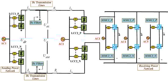
Figure 1.
Bipolar hybrid cascaded multi-terminal HVDC system topology.
- In a hybrid cascaded system, where the receiving LCCs and MMCs are connected in series and two voltage levels exist within the transmission line, stable operation requires the presence of two converter stations dedicated to voltage control. Additionally, due to the series configuration of system converters, at least one converter station must function as a power control unit to regulate system power flow effectively.
- The operating status of the hybrid cascaded MTDC system can be determined using Equation (1), as shown below:
Figure 2 is the simplified topology of a bipolar hybrid cascaded multi-terminal HVDC system. The most rudimentary variant is formulated to facilitate the comprehension of the fundamental topology.
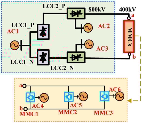
Figure 2.
Simplest form of bipolar hybrid cascaded multi-terminal HVDC system topology.
2.3. Fault Current Theory Analysis Under Asymmetrical DC Faults
In hybrid cascaded HVDC transmission, pole–ground, pole–pole, and pole–pole-to-ground faults are the severe types of asymmetrical DC faults. During such events, both the MMC and the LCC branches inject fault currents into the DC network. The total transient response is therefore the superposition of MMC-side capacitor discharge and LCC-side line current dynamics. This section develops analytical expressions for each component, beginning with the MMC contribution and followed by the LCC contribution [30]. The Complex frequency-domain modeling of parallel MMCs configuration is shown in Figure 3.
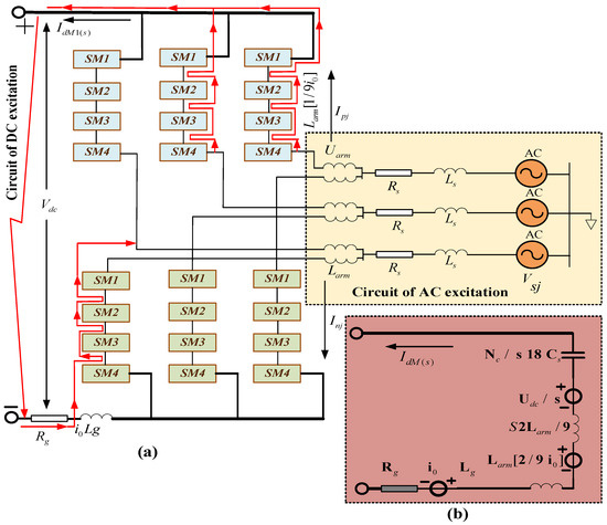
Figure 3.
Complex frequency-domain modeling of parallel MMCs configuration. (a) Detailed model of MMC1; (b) three parallel MMCs.
2.3.1. Fault Current Contribution of MMCs
When an asymmetrical DC fault occurs, the excitation source driving the MMC response is composed of three parts: (i) the stored energy of the submodule capacitors, (ii) the initial current in the bridge arm reactor, and (iii) the current in the DC smoothing reactor.
- (a)
- DC-Side Contribution
- Pole–ground DC fault
A pole–ground DC fault occurs when one DC conductor (positive or negative pole) comes into direct contact with the ground. This creates an asymmetrical DC fault because the faulty pole collapses while the intact pole retains nearly its pre-fault potential.
Each submodule capacitor can be assumed to hold the same voltage , reflecting the principle of constant-capacitance storage across the modules. Under this assumption, the equivalent capacitance of one phase-leg stack is derived as
where is the submodule capacitance and is the number of submodules per phase. Considering the three phases in parallel, the effective capacitance that contributes to the DC-side transient is
The effective inductance of the DC loop is
with an associated time constant,
where is the grounding resistance.
The governing second-order equation for the MMC fault current is
subject to the initial conditions
where is the initial DC voltage of the converter.
The characteristic parameters are
The closed-form solution is
with
These equations describe the exponentially damped oscillation of the MMC-side fault current under asymmetrical DC fault conditions.
- Pole–pole DC fault
For a direct short circuit between positive and negative poles, the grounding path is not dominant. Instead, the two DC pole capacitors discharge against each other through line impedance. The effective capacitance doubles because both poles contribute
The equivalent inductance involves both pole arms:
The governing current equation becomes
where is the inter-pole resistance. The response follows the same exponential–oscillatory form as (21) but with the parameters , by (11)–(13).
- Pole–pole-to-ground fault
In this configuration, both poles discharge to the ground simultaneously. The effective capacitance is approximately
i.e., two parallel branches of pole capacitors discharging into the ground. The loop inductance includes both arm inductors and the grounding reactor:
The differential equation is
which again leads to a damped oscillation but with stronger initial current peaks, since both poles release energy into the fault.
- (b)
- AC-Side Contribution
A balanced three-phase AC network does not inject any net DC current into the DC link, since the zero-sequence component cancels it out. This can be verified compactly using phasor representation. For the upper arm of phase , the steady-state current phasor is
where is the phase voltage amplitude, is the AC fundamental angular frequency, is the AC-side resistance, is the AC reactor, and is the arm inductance.
The instantaneous arm currents satisfy the balanced condition
Thus, the AC-side currents contain only AC-frequency components and contribute no net DC injection. Before converter blocking, the transient DC-side response therefore dominates the fault current.
- (c)
- Superposition of DC- and AC-Side Excitations
Because the system response is linear during the short pre-blocking interval, the total arm current can be expressed as the superposition of DC- and AC-side contributions:
where
is the DC-side modal current response.
is the AC-side bridge-arm current, given by
Here,
2.3.2. LCC Contribution Under Different Asymmetrical DC Faults
The LCC branch contributes to the asymmetrical DC fault current through the DC line impedance and the terminal voltage difference between the rectifier and inverter stations. The current satisfies
where are the line resistance and inductance, and are the rectifier and inverter DC voltages.
The characteristic time constant is
The solution of (24) is
with determined by initial conditions.
The inverter-side DC voltage can be expressed as
where is the DC smoothing inductance, is the number of six-pulse bridges per pole, is the inverter AC bus voltage, is the transformer ratio, is the transformer leakage reactance, is the inverter firing angle, and denotes auxiliary modulation.
2.4. Asymmetrical DC Faults Classifications of the Bipolar Hybrid Cascaded MTDC System
The classification of DC faults is examined comprehensively. DC faults in the bipolar hybrid cascaded MTDC system are categorized based on their characteristics and frequency of occurrence. The four primary asymmetrical DC faults in the LCC segment of the bipolar hybrid cascaded MTDC system are examined. The four asymmetrical DC faults are internal faults occurring between the two LCCs. The combined section of the LCCs and MMCs experiences three primary asymmetrical DC internal faults. Three principal asymmetrical DC internal defects pertaining to the MMCs are also examined.
In Figure 4, the DC faults are systematically classified into four distinct categories, specifically categorized as category 1, category 2, category 3, and category 4. Focusing on the LCCs’ side, we consider category 1, which encompasses a total of four DC fault types, namely DC fault 1, DC fault 2, DC fault 3, and DC fault 4. Within the hybrid segment of the bipolar hybrid cascaded MTDC system, category 2 is examined; in this category, we delineate three specific DC faults, identified as DC fault 5, DC fault 6, and DC fault 7. Regarding the MMC section, we investigate category 3, which also comprises three notable DC faults. These DC faults are designated as DC fault 8, DC fault 9, and DC fault 10. Category 4 is derived from the entire hybrid cascaded system, wherein multipoint DC faults are elucidated. Such multipoint DC faults have the potential to manifest in any segment of the system, potentially arising in the LCC section while, concurrently, another fault may occur within the MMC segment. In this paper, an illustrative example of a multipoint DC fault is presented.
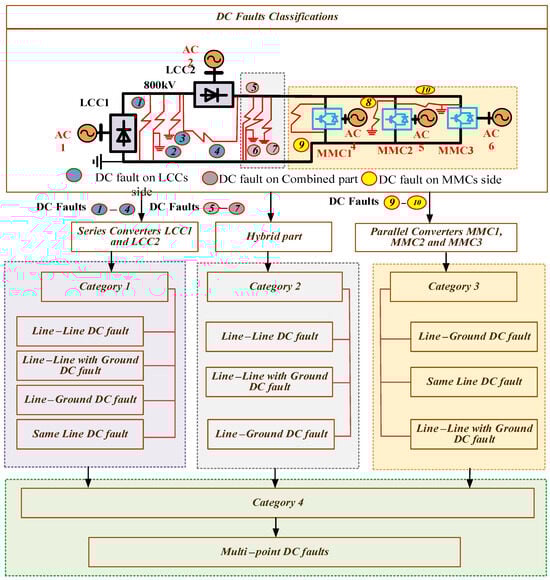
Figure 4.
Classification of DC faults in bipolar hybrid cascaded MT-HVDC system.
2.4.1. Category 1: Asymmetrical DC Faults in the Series Part of the Bipolar Hybrid Cascaded MTDC System
In category 1, four DC faults are described, which are shown in this Figure 5. These DC faults are on the series part of the bipolar hybrid cascaded multi-terminal HVDC system.
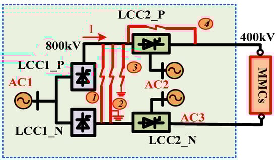
Figure 5.
Asymmetrical DC faults between the LCCs of a bipolar hybrid cascaded multi-terminal HVDC system.
- DC fault 1: This asymmetrical DC fault is an internal fault occurring between the two LCCs. DC fault 1 is a line-to-line fault. In a line–line fault, one end is connected to the positive terminal of both LCCs, while the other end is connected to the negative terminal of both LCCs. This line-to-line DC fault is ungrounded. Figure 4 illustrates that, during an asymmetrical DC internal line-to-line short-circuit fault between the two LCCs, LCC1 and LCC2 direct the fault current towards the fault site at both extremities of the DC line. At this moment, the instantaneous increase in current and the direction of the abrupt current change align with the direction of current flow. At this fault location, the direction of the fault current is positive.
- DC fault 2: This asymmetrical DC fault is the internal fault occurring between the two LCCs. This DC fault 2 is a line-to-line DC fault with grounding. Figure 4 demonstrates that, during an asymmetrical DC internal line-to-line short-circuit fault, the impact on the ground is similar, with little difference, as confirmed by the subsequent simulation results. A minimal disparity in the increase in current is observed when comparing this fault with line-to-line DC faults with the ground.
- DC fault 3: This asymmetrical DC fault is an internal fault occurring between the two LCCs. The third asymmetrical DC fault depicted in Figure 5 is identified as the line-to-ground DC fault. An asymmetrical DC internal line-to-ground fault on a positive line can cause an abrupt change in current and voltage.
- DC fault 4: This asymmetrical DC fault is also an internal fault occurring between the two LCCs. The fourth DC fault in the LCC section is a same-line DC fault, occurring on the same line as the positive terminal. The first end is connected to the LCC2, while the second end is connected to the LCC2.
Table 1 shows DC faults 1, 2, 3, and 4. Each fault is categorized based on its distinct characteristics and impact on system performance.

Table 1.
DC faults 1, 2, and 3 and DC fault 4.
2.4.2. Category 2: Asymmetrical DC Faults on the Hybrid Part of the Bipolar Hybrid Cascaded MTDC System
In category 2, three DC faults are described, which are shown in Figure 6. These DC faults are on the hybrid part of the bipolar hybrid cascaded multi-terminal HVDC system.
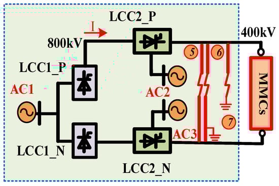
Figure 6.
Asymmetrical DC faults between the two LCCs and between the LCC2 and MMCs of the bipolar hybrid cascaded multi-terminal HVDC system.
- DC fault 5: This asymmetrical DC internal fault occurs between the two LCCs and the MMCs. DC fault 5 refers to a line-to-line DC fault. In this DC fault, one end is linked to the positive terminal of the LCC2 and MMCs, while the other end is connected to the negative terminal of the LCC2 and MMCs.
- DC fault 6: This asymmetrical DC internal fault occurs between the two LCCs and the MMCs. This DC asymmetrical fault is a line-to-line DC fault involving the ground. DC fault 6’s first end is connected to the positive terminal of the LCC2 and MMCs.
- DC fault 7: DC fault 7’s first end is connected to the positive terminal of the LCC2 and MMCs, and its second end is connected to the ground. This is a line-to-ground DC fault.
Table 2 shows DC faults 5, 6 and 7. Each fault is categorized based on its distinct characteristics and impact on system performance.
Table 2.
DC fault 5, DC fault 6 and DC fault 7.
2.4.3. Category 3: Asymmetrical DC Faults in the MMC Part of the Bipolar Hybrid Cascaded MTDC System
In category 3, three DC faults are described, which are shown in this Figure 7. These DC faults are on the MMC part of the bipolar hybrid cascaded multi-terminal HVDC system.
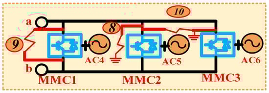
Figure 7.
Asymmetrical DC faults between MMCs.
- DC fault 8: This asymmetrical DC fault is internal to the MMCs. DC fault 8 refers to the line-to-ground fault at MMC2. DC fault 8’s first end is connected to the positive terminal of MMC2 and its second end is connected to the ground. This DC fault occurs within the boundaries of the modular multilevel converters (MMCs), and this particular fault is also referred to as a midpoint DC fault.
- DC fault 9: DC fault 9 is associated with the same-line fault. This DC fault is located on the MMC1. This is sometimes referred to as a midpoint DC fault as well.
- DC fault 10: The first end of this fault is attached to the MMC2, while the second end is connected to the MMC3. This problem is also referred to as a line–line DC fault with ground. All these DC flaws are plainly illustrated in Figure 7.
Table 3 presents DC faults 8, 9 and 10 with each fault categorized according to its unique characteristics and its impact on system performance.
Table 3.
DC fault 8, DC fault 9 and DC fault 10.
2.4.4. Category 4: Multipoint Asymmetrical DC Faults in the Bipolar Hybrid Cascaded MTDC System
In category 4, the complexities associated with asymmetrical multipoint DC faults are examined. These multipoint asymmetrical DC faults represent internal anomalies occurring between the two converter types, namely the LCCs and MMCs. Multipoint faults are characterized by their potential to manifest at various locations simultaneously. Given the extensive array of possible multipoint DC fault combinations, this manuscript presents a singular illustrative example; additional combinations will be elaborated upon in subsequent scholarly endeavors.
3. New Classification of DC Faults and Corresponding Control Demand Analysis
3.1. Simulations of the Asymmetrical DC Faults of the Bipolar Hybrid Cascaded MTDC System
The bipolar hybrid cascaded multi-terminal HVDC system is depicted in Figure 1. The simulation of the bipolar hybrid cascaded multi-terminal HVDC system is executed within the Simulink PSCAD/EMTDC environment. Two arrays of 12-pulse LCCs are configured on the rectifier side, while analogous arrangements of 12-pulse LCCs are established on the inverter side. These dual groups of 12-pulse LCCs are serially interconnected with three bipolar MMCs. The aforementioned three bipolar MMCs are interconnected in parallel with one another. Each of the three bipolar MMCs shares common upper and lower busbars. Furthermore, these three bipolar MMCs are additionally linked to their respective individual bus systems. The LCC employs thyristor technology; AC filters are implemented to mitigate the harmonic distortions produced by the thyristors. Additionally, DC filters are utilized to diminish the ripples in the DC output, thereby enhancing system stability. A constant firing angle and extinction angle are maintained when the converters are activated, facilitating the cessation of current flow to zero within the thyristors. Inductors function as filters to minimize the ripples present in the DC current. In this context, five-level MMCs are conceptualized, with each arm of the MMC comprising four capacitors utilized to achieve intermediate voltage levels. Moreover, arm inductors are incorporated to suppress fault currents and to restrict circulating currents within these MMC arms. Insulated IGBTs are employed in the MMCs to regulate the operational dynamics of the submodules within these converters. Simultaneously, the MTDC system establishes both neutral and pole lines in a symmetrical configuration, positioned on both the rectifier and inverter sides to mitigate overall harmonics and the discharge current at the point of fault caused by a DC connection short-circuit. DC transmission lines facilitate the interconnection between both segments of the LCCs. In this specific topology, DC filters are also utilized to prevent the proliferation of harmonic distortions.
In the bipolar hybrid cascaded MTDC system, the LCC at the rectifier terminal functions under a constant current control paradigm to regulate the direct current. Conversely, the LCC situated at the inverter terminal employs a constant direct current voltage control strategy as its primary regulatory mechanism during standard operational conditions, while the extinction angle control method is implemented as an ancillary regulation approach during DC fault scenarios. MMC1 is configured for constant DC voltage regulation, whereas both MMC2 and MMC3 are set to constant active power control to facilitate equitable power distribution. Furthermore, all three MMCs are designed to maintain constant reactive power control.
This simulation provides a comprehensive discussion on the characterization of DC faults, along with the acquisition of main DC fault simulation curves. These curves demonstrated that the results are valid and the research was conducted thoroughly. For each DC fault, a simulation is conducted to ascertain its characteristics, followed by a comparative analysis of the characteristics associated with each DC fault, ultimately leading to a new classification of the characterization of these DC faults. The various cases delineated below elucidate the simulation outcomes and characteristics inherent to DC faults.
Table 4 lists the primary parameters of the bipolar hybrid cascaded multi-terminal HVDC system.
Table 4.
Primary parameters of the bipolar hybrid cascaded multi-terminal HVDC system.
- In Case A, four types of DC faults were examined; the faults were classified under category 1, pertaining to the LCC segment. Independent simulations were conducted for each fault, identifying their characteristics, assessing similarities, and drawing conclusions. The results were scrutinized, and those with similar characteristics were categorized separately. This led to the establishment of a new classification of characterization groups, which are detailed in Section 3.2.1. The simulations and characteristics of these faults were then used to classify them.
- In Case B, three DC faults, falling under category 2, were examined and their simulations conducted. These faults were related to the hybrid segment of the system and were challenging to simulate. Similarly to Case 1, all simulation outcomes were scrutinized and characterizations were deduced, leading to the identification of a new classification of DC fault characterizations, as presented in Section 3.2.2.
- In Case C, we analyzed three DC faults classified under category 3, which is associated with MMCs. Simulations and outcomes were scrutinized, leading to a new characterization classification, which is presented in Section 3.2.3.
- In Case D, multipoint DC faults were addressed. These DC faults belong to category 4. The combinations of these DC faults are numerous. A selection of combinations of DC faults was considered in this paper, and simulations of these DC faults were executed. The combinations of these DC faults include (a) DC fault 1 and DC fault 2 and (b) DC fault 1 and DC fault 3. Following the completion of the simulations, the characteristics of these DC faults were identified, leading to the creation of a new classification of these DC faults, which is illustrated in Section 3.2.4.
3.2. New Classification of Characterization of Asymmetrical DC Faults of Bipolar Hybrid Cascaded MTDC System
Various forms of DC faults exist, including short circuit DC faults, open circuit DC faults, ground DC faults, overcurrent DC faults, arcing DC faults, overvoltage DC faults, insulation DC faults, and reverse polarity DC faults, among others. The system is developed to describe the characteristics of the main DC faults; the effects of these main types of DC faults on the system are described one by one. The fault curves describe at what time the current and voltage increase or decrease during the faults. After studying these DC fault characteristics, the system can be easily protected and a fault recovery strategy can be designed easily. Without the study of these main kinds of DC faults, fault recovery is a very big challenge. The aforementioned scenarios of DC faults have been outlined; now, the theoretical details regarding the effects of these DC faults are given.
3.2.1. Characterization of DC Faults in Category 1
The characteristics DC fault 1 and DC fault 2 are described here. DC fault 1 is the line–line DC fault between the two LCCs on the series part of the system. As this fault occurs the current increases suddenly. The excessive fault current puts at risk the secure functioning of the DC system. In this case the voltage also suddenly decreases; this is very dangerous for the whole system because the bus capacitor, which is used to balance or stabilize the system, is discharged abruptly, which is the main cause of the damage to the system. This increase in the high current can damage the sub-modules of the MMCs. DC fault 2 is a line–line DC fault with ground and DC fault 3 is a line-to-ground fault. The characteristics of these two faults are the same, which is why one explanation for the faults is given here. This fault is more dangerous for the system due to the low impedance of the bipolar hybrid cascaded HVDC system, which can affect the converters and even the AC side of the system. Here the sharp increase in the current due to low impedance and both the LCCs can send and contribute the current to this fault line because these two converters are connected to this DC fault. The existing surge will extend towards both extremities of the fault, exerting stress on the converters or DC line components. Due to this fault the DC voltages also decrease at both LCCs’ terminals as well as decrease at all three MMCs, which is not good for the system.
The results of the simulations pertaining to DC fault 1, DC fault 2, and DC fault 3 are presented in Figure 8. The occurrence of a DC fault resulted in an abrupt increase in the current across all modular multilevel converters (MMCs), as depicted in Figure 8a. Figure 8b demonstrates the voltage levels across all MMCs. Figure 8c illustrates the active power associated with all MMCs. Figure 8d portrays the reactive power for all MMCs.
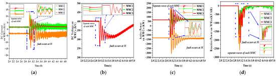
Figure 8.
(a) DC current of Category 1 on MMCs, (b) DC voltage on of Category 1 MMCs, (c) DC active power of Category 1 on MMCs, (d) DC reactive power of Category 1 on MMCs.
The attributes of the current observed on the rectifier side of the hybrid cascaded multi-terminal direct current (MTDC) system are illustrated in Figure 9a. The voltage characteristics are depicted in Figure 9b. The representation of active power is presented in Figure 9c. The reactive power on the rectifier side of the system is delineated in Figure 9d.
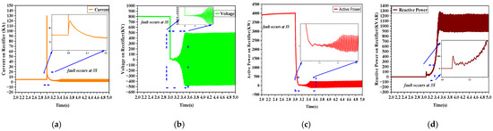
Figure 9.
(a) Current of rectifier, (b) voltage of rectifier, (c) active power of rectifier, (d) reactive power of rectifier.
As the fault occurs, the current on the inverter side is depicted in Figure 10a, while the voltage on the inverter side is illustrated in Figure 10b. The active power is illustrated in Figure 10c. Figure 10d illustrates reactive power.
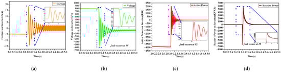
Figure 10.
(a) Current of inverter, (b) voltage of inverter, (c) active power of inverter, (d) reactive power of inverter.
3.2.2. Characterization of DC Faults in Category 2
DC fault 4 is a very dangerous fault and its detection is quite difficult because its first end is connected between the two LCCs, LCC1 and LCC2, while its other end is connected between MMCs and LCC2. As the fault’s first end is between the two LCCs, it is an unwanted path which will be the cause of overheating, malfunction, and overcurrent, and it can also be the cause of voltage overloading, voltage spikes, and voltage imbalance of the system on the DC side. This overcurrent can damage the valves of the converters and these converters become faulty; due to these faulty converters, the overall power of the system will be reduced, causing a lot of power loss as well as interrupting the system. Due to the instability of the converters, there will be instability in the power control, especially on the side of these two LCCs. If the fault occurs for too long, or if the fault is permanent, then it can damage the equipment of the MMCs as well as the equipment of the LCCs, like thyristors in the LCCs and IGBTs in the MMC modules.
The simulation outcomes for DC fault 4 are presented in Figure 11. MMC1, MMC2, and MMC3 exhibit the present behavior following the DC fault. The system remained stable until 3 s, at which point a fault occurred, resulting in a significant spike in current magnitude across all MMCs, followed by a gradual decrease in current magnitude over time. The behavior of voltage, active power, and reactive power also changes when a DC fault occurs.
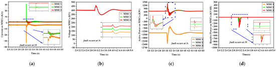
Figure 11.
(a) DC current of fault 4 on MMCs, (b) DC voltage of fault 4 on MMCs, (c) DC active power of fault 4 on MMCs, (d) DC reactive power of fault 4 on MMCs.
3.2.3. Characterization of DC Faults in Category 3
DC fault 5 is a very serious fault. As this fault occurs, the current magnitude rises up to 550 KA. After some milliseconds, the current decreases to 80 KA. This is still a very high-magnitude current. But the magnitude of the MMC3 current remains at −45 KA. As this fault occurs, there are a lot of increases in current and sudden decreases in voltage to zero. Before the converter blockage, the upper and lower arms of the MMCs are discharged and take a short path, which is the DC line-to-line path. Due to the discharge energy of these capacitors, the system becomes unstable and there is a lot of power loss, and due to many rising currents, the system may be damaged. DC fault 6 is a line–line with ground fault and DC fault 7 is a line-to-ground Dc fault. When both these faults occur, the currents of MMC1 and MMC2 rise up to 550 KA and −550 KA while the MMC3 magnitude rises up to −45 KA.
The MMC graph for DC fault 5, DC fault 6, and DC fault 7 is presented in Figure 12. The attributes of these faults are identical; thus, the current is depicted in Figure 12a, voltage in Figure 12b, active power in Figure 12c, and reactive power in Figure 12d. The system maintained stability until 3 s, when a failure transpired, causing a substantial rise in current magnitude across all MMCs. Subsequently, the current magnitude commenced to diminish after a period. Additionally, there is variation in voltage, as well as active and reactive power, after a fault.
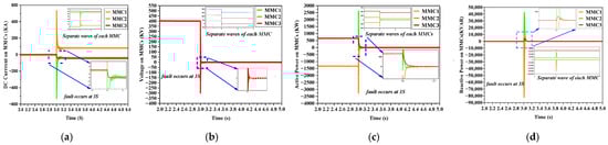
Figure 12.
(a) DC current on MMCs, (b) DC voltage on MMCs, (c) DC active power on MMCs, (d) DC reactive power on MMCs.
3.2.4. Characterization of DC Fault Category 4
DC fault 8 is a midpoint fault. This fault is a line–ground DC fault. This fault is at MMC2. This midpoint fault transpires between the parallel MMCs, specifically the DC midpoint fault, which occurs between MMC2 and MMC3. This fault is located at the positive terminal and is also grounded. Both MMCs convey the augmentation in current to this pathway. The fault zone under the specified conditions is illustrated in Figure 6 and is mostly situated in the valve hall, hence the typical occurrence is a continuous ground fault. At t = 3 s, when this fault transpires, the current of MMC1 escalates to 640 kA, while the current magnitude of MMC2 is −640 kA. The current magnitude of MMC3 is −45 kA and remains constant.
DC fault 9 is a same-line fault. This fault is on MMC1. This fault is a very severe fault. At t = 3 s, a fault occurs, causing an enormous spike in current, with MMC1 reaching a magnitude of 550 kA. After a few milliseconds, the current rise diminishes, stabilizing at a substantial 100 kA, while the voltage abruptly drops to zero. The magnitude of MMC2 is −550 kA following the DC fault, and after several milliseconds, it decreases to −100 kA; its voltage is also zero post-fault. The magnitude of MMC3 is 42 kA following the DC fault, remaining constant throughout the fault, with voltage also at zero. As the current increases due to this fault and the voltage decreases to zero, the system is totally imbalanced and then MMCs on the inverter side are blocked within milliseconds so that the system cannot be affected due to these severe DC faults. In the steady state, the currents of the LCC and MMC are equivalent. Due to the production standards, the insulated-gate bipolar transistor (IGBT) and capacitor, which are critical components of the MMC submodule, exhibit elevated prices and limited overcurrent capabilities. Prior to the blockage of the MMC, the IGBT and capacitor must endure overcurrent at designated thresholds; if either the IGBT or capacitor sustains damage due to the overcurrent issue, it will compromise the equipment’s longevity and may jeopardize the system’s capacity to operate safely and reliably.
DC fault 10 is a midpoint line–line DC fault with ground. This DC fault is on MMC2. The fault manifests at 3 s, resulting in a dramatic spike in current. The large fault current jeopardizes the safe operation of the DC system. In this scenario, the voltage also experiences a quick fall, posing a significant risk to the entire system, since the bus capacitors utilized for balancing or stabilizing the system discharge abruptly, which is the primary source of system damage. The elevation of the high current may harm the sub-modules of the MMCs.
Figure 13 provides a detailed depiction of DC fault 8, DC fault 9, and DC fault 10 within the bipolar hybrid cascaded multi-terminal HVDC system. The pictures depict the three currents: MMC1, MMC2, and MMC3. When the fault occurs, the current increases as the voltage level diminishes to zero. This failure also alters active power and reactive power.
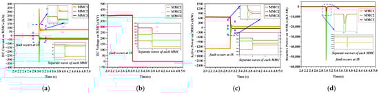
Figure 13.
(a) DC current on MMCs, (b) DC voltages on MMCs, (c) DC active power on MMCs, (d) DC reactive power on MMCs.
3.2.5. Characterization of DC Fault Category 5
The attributes of DC fault 1 and DC fault 2 are elucidated in the following text. DC fault 1 pertains to the line-to-line DC fault occurring between the two-line commutated converters (LCCs) within the series section of the system. DC fault 2 refers to the line-to-line DC fault with the ground between the two LCCs. These faults occur at the same time. And in this way, DC fault 1 and DC fault 3 represent line-to-ground faults which occur at same time. These faults are called multi-terminal DC faults. Upon the onset of this fault, there is a precipitous increase in current. The resultant excessive fault current jeopardizes the secure operation of the DC system. Concurrently, there is a sudden reduction in voltage, which poses a significant threat to the entire system as the bus capacitors, employed for balancing or stabilizing the system, experience abrupt discharges, primarily instigating system damage. The characteristics of these two faults exhibit similarities, thus warranting a singular elucidation for one of them. This fault presents a greater risk to the system owing to the low impedance characteristic of the bipolar hybrid cascaded high voltage direct current (HVDC) system, which may adversely impact the converters and potentially the alternating current (AC) side of the system. In this scenario, the sharp increase in the current, which can be attributed to low impedance, allows both LCCs to contribute current to the fault line, as these converters are interconnected with the DC fault. The existing surge will propagate towards both extremities of the fault, imposing stress on the converters or the components of the DC line. As a consequence of this fault, the DC voltages at both terminals of the LCCs, as well as at all three MMCs, experience a decline, which is detrimental to the integrity of the system.
In a multipoint DC fault, two faults occur simultaneously. The two pairs of faults examined are (a) DC fault 1 and DC fault 2 and (b) DC fault 1 and DC fault 3 to elucidate the notion of multipoint DC fault. Figure 14a illustrates the direct current of the three MMCs. Figure 14b illustrates the voltages of the three MMCs, Figure 14c depicts the active power of the MMCs, and Figure 14d presents the reactive power of the MMCs.
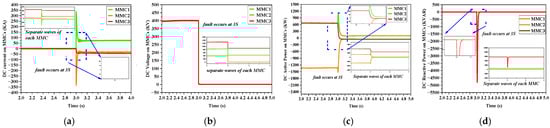
Figure 14.
(a) Multipoint DC current of MMCs, (b) multipoint DC voltage of MMCs, (c) multipoint DC active power of MMCs, (d) multipoint DC reactive power of MMCs.
3.3. Control Demand of the DC Faults
This paper discusses several types of DC faults and emphasizes the significance of control measures to mitigate these faults and protect the entire system. Line–line DC faults, line-to-ground DC faults, same-pole DC faults, and multipoint DC faults are examined comprehensively, with the control requirements for each type of DC fault provided sequentially to ensure system security.
Table 5 articulates the positive and negative magnitude values associated with voltages and currents within MMCs following the incidence of DC faults. This section elucidates both the primary DC fault values and the multipoint DC fault values for comprehensive examination. From the analysis, five categories enumerated in this table and the corresponding control demand of each category are derived from Table 5.
Table 5.
Positive and negative peak magnitude values of voltages and currents on MMCs after DC faults.
This chronological representation in Figure 15 is constructed in accordance with the new classifications of characterizations associated with DC faults. It illustrates that specific measures are necessitated under conditions of DC faults, and upon the resolution of such faults, alternative measures are mandated.
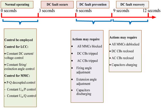
Figure 15.
Chronological representation of new classification of characteristics of DC faults.
The control demand pertaining to the new classifications of characteristics associated with DC faults are delineated comprehensively in five categories.
3.3.1. Control Demand of Category 1 DC Faults
Figure 8 shows the results of category 1. In category one, three distinct DC faults exhibit the same characteristics, all occurring on the LCC side. These three DC faults comprise a line–line DC fault, line–line with ground DC fault, and line–ground DC fault. These DC faults are exceedingly perilous, as they induce an abrupt escalation in the amplitude of current, thereby leading to a significant augmentation in current intensities. The regulatory requirements pertaining to these DC faults are outlined as follows.
- Following a DC fault, the current can experience a sudden surge, making it imperative to promptly reduce the DC voltage to limit fault currents. The LCC reverse blocking feature should be immediately engaged to restrict the erroneous current. Under normal conditions, the LCC operates within a current range of 2 kA to 5.5 kA, but a fault can cause the current to rise significantly, posing a risk to the entire LCC assembly and potentially destabilizing the system. Similarly, MMCs, which typically withstand currents between 1.5 kA and 3 kA, may be exposed to currents exceeding their capacity during a DC fault, necessitating protective measures to mitigate the impact of these excessive currents and preserve system stability.
- During this DC fault, the current rises to approximately 13 kA while the voltage drops from 400 kV to 285 kV. To maintain system stability, it is necessary to adjust the MMCs’ DC voltages and retard the firing angle to limit the fault current. There is no immediate need to trip the DC circuit breaker, as the fault may self-clear without causing significant current escalation over time. Maintaining the system’s impedance is also crucial, since the fault creates a short-circuit path that reduces impedance and induces a sudden current spike, which could potentially damage converters such as MMCs.
- MMCs and LCCs are designed to rapidly adjust their output voltage in real time to respond to disturbances. To mitigate DC fault currents, the firing angle at the rectifier side should be increased, while the MMC provides reactive power support to stabilize voltages. The pole unaffected by the fault must be maintained to enable partial power delivery, and dynamic adjustments to the extinction angle on the inverter side help minimize commutation overlap. Additionally, effective integration of the voltage control error ensures a seamless transition between the system’s control modes, maintaining overall stability during fault conditions.
3.3.2. Control Demand of Category 2 DC Faults
Figure 11 shows the results of category 2. DC fault 4 is illustrated as an example, with the first end located before LCC2 and the second end situated after LCC2, both at the same pole, which is the positive pole. This fault is quite intricate due to its bifurcation into two distinct regions. The control requirements for this type of DC faults are as follows.
- For this moderate DC fault, it is not necessary to trigger the protection mechanisms of the DC or AC circuit breakers, as both LCC and MMC units can effectively manage the disturbance, and the resulting current increase is not critically severe. The LCC reverse blocking function should be promptly activated to limit the fault current, while the MMC must adjust the DC voltage reference to quickly reduce the positive terminal voltage. Additionally, the capacitors within the converters remain largely unaffected, as the short-duration nature of this fault allows it to be adequately mitigated by the LCCs and MMCs.
- To mitigate the fault current flowing through both ends of a significant DC fault, it is necessary to adjust the DC voltage across the entire positive pole and modify the LCC to manage commutation, thereby preventing rectifier overload. Simultaneously, the MMC on the inverter side must inject reactive power to stabilize the associated AC grid, providing essential support to maintain overall system stability during the disturbance.
- Subsequent to this fault, the voltages at the positive pole experience a fast decline, rendering the management of the negative voltage a significant challenge due to the system’s instability.
3.3.3. Control Demand of Category 3 DC Faults
Figure 12 illustrates the outcomes pertaining to category 3. Within the first category, three unique DC faults demonstrate analogous characteristics; all DC faults are within the hybrid part of the system. The aforementioned three DC faults encompass a line-to-line DC fault, line-to-line with ground DC fault, and line-to-ground DC fault. These DC faults are recognized as highly hazardous, thereby necessitating a comprehensive description of the control measures required.
- During this severe fault condition, the current may escalate to extraordinary levels of up to 500 kA, far exceeding the tolerance limits of both the LCCs and MMCs. Simultaneously, the voltage shifts from 400 kV to −300 kV, indicating a polarity inversion that represents a critical fault. Under such circumstances, it is imperative to promptly disengage the DC circuit breaker and activate the AC circuit breaker, as the excessive current poses serious risks to both the AC and DC segments of the system. The abrupt discharge of capacitors further amplifies the fault current, threatening system stability, while the inductors contribute to the escalation by releasing stored energy, which may ultimately lead to overheating and potential damage.
- To protect the IGBTs and other sensitive components, it is essential to block all MMCs during a DC fault. Retarding the firing angle helps limit the fault current, while maintaining the system’s impedance is critical to prevent excessive current escalation. The occurrence of a DC fault creates a short-circuit pathway, reducing system impedance and inducing a sudden surge in current, which can potentially damage converters such as MMCs. Both MMCs and LCCs are designed to rapidly adjust their output voltage in real time, providing additional support to mitigate the fault impact and maintain system stability.
- To mitigate the DC fault current, it is advisable to increase the firing angle at the rectifier side. Additionally, MMCs should be utilized for reactive power support to maintain voltage stability, while the pole unaffected by the fault must be reinforced to enable partial power delivery and ensure continued system operation.
- Dynamic adjustment of the extinction angle on the inverter side is necessary to diminish commutation overlap. To ensure a seamless transition between the various control modes of the system, it is crucial to effectively integrate the voltage control error.
3.3.4. Control Demand of Category 4 DC Faults
Figure 13 illustrates the outcomes pertaining to category 4. Within category 4, three unique DC faults demonstrate analogous characteristics, all manifesting within the hybrid component of the system. These DC faults are situated on the side of the MMCs. Such DC faults are alternatively referred to as midpoint DC faults. Within this classification, the occurrence of DC faults results in an abrupt decline in voltage to a level of zero, coupled with a significant increase in current.
- In this type of catastrophic DC fault, the current can surge to levels as high as 350 kA while the corresponding voltage collapses to zero, making it imperative to promptly activate the DC circuit breakers to mitigate the fault condition.
- During such faults, the AC circuit breakers must also be activated, as the instantaneous voltage drop to zero causes the capacitors to discharge, making it essential to recharge them once the fault has been cleared.
- To alleviate the DC fault current, it is necessary to retard the firing angle at the rectifier terminal, thereby increasing the effective system impedance following the fault. Both MMCs and LCCs are designed to rapidly adjust their output voltage in real time, which further supports the suppression of the fault current and contributes to maintaining system stability.
- In the event of a DC fault, the MMC can be employed to provide reactive power support, thereby ensuring voltage stabilization. At the same time, it is crucial to stabilize the pole unaffected by the fault to enable partial power delivery, while dynamic adjustments to the extinction angle further contribute to maintaining system stability during the disturbance.
3.3.5. Control Demand of Category 5 DC Faults
Figure 14 illustrates the outcomes pertaining to category 5. Within the category 5, multipoint DC faults demonstrate analogous characteristics. Within this classification, the occurrence of DC faults results in an abrupt decline in voltage to a level of zero, coupled with a sudden increase in current.
- The occurrence of multipoint DC faults significantly alters the operational characteristics of the modular multilevel converters, as the current rises sharply while the voltage drops to negligible levels. To mitigate this condition, it becomes imperative to promptly trip both the DC and AC circuit breakers.
- The capacitors undergo a rapid discharge as a consequence of this DC fault.
- To mitigate the DC fault current, it is essential to retard the firing angle. Preserving the system’s impedance following the occurrence of a DC fault is critical. The initiation of this DC fault creates a short circuit pathway, leading to a decrease in system impedance, which in turn results in an abrupt increase in current. The resultant surge in current of exceedingly high magnitude poses a risk of damage to the converters, including MMCs.
- MMCs and LCCs adjust the output voltage in real-time scenarios. In order to attenuate the DC fault current, it is advisable to augment the firing angle on the rectifier side and to employ the MMC for reactive power compensation to ensure voltage stabilization.
All the new classification categories of characterization of DC faults are shown in Table 6.
Table 6.
Control demand and system response after asymmetrical DC fault occurrence.
4. Conclusions
This paper analyzed the DC fault mechanism and characteristics of DC faults, which constitute the most significant failure in DC bipolar hybrid cascaded multi-terminal HVDC systems. The bipolar hybrid cascaded multi-terminal HVDC system integrates the MMC for system support with the LCC for high-power transmission. The characteristics of the proposed strategy are delineated as follows:
- Developed a comprehensive simulation of a bipolar hybrid cascaded multi-terminal HVDC system and executed simulations of principal categories of DC faults. The effects of failures on HVDC bipolar systems were comprehensively analyzed, including a meticulous assessment of the main DC fault characteristics.
- Classified the DC faults based on their distinctive characteristics and delineated them into an innovative categorization of DC faults. The characteristics of current, voltage, active power, and reactive power were analyzed in relation to the effects of a DC fault.
- The requisite control demand for the mitigation of DC faults was proposed based on the newly established classification of DC fault characteristics.
- Line–line DC faults, line-to-ground DC faults, same-pole DC faults, and multipoint DC faults were examined comprehensively, with the control requirements for each type of DC fault provided sequentially to ensure system security.
Author Contributions
M.A.M.: conceptualization, data curation, formal analysis, methodology development, validation, and manuscript writing; Z.L.: conceptualization, funding acquisition, methodology, provision of resources, and supervision; W.M.: critically revised the manuscript. All authors have read and agreed to the published version of the manuscript.
Funding
This work was supported in part by the National Key Research and Development Program of China (Grant No. 2024YFB2408900).
Data Availability Statement
The original contributions presented in this study are included in the article. Further inquiries can be directed to the corresponding author.
Conflicts of Interest
All the authors declare no conflicts of interest.
Abbreviations
The following abbreviations are used in this manuscript:
| DC | Direct current | t | Time |
| AC | Alternating current | P | Active power |
| MMC | Modular multilevel converter | Q | Reactive power |
| HVDC | High voltage direct current | DC voltages of rectifier | |
| MTDC | Multiterminal high voltage direct current | DC voltages of inverter | |
| LCC | Line commutated converter | High-end DC voltages | |
| DCCB | DC circuit breaker | R | Resistance |
| V | Voltage | Reactance | |
| I | Current | F | Sub-modules capacitor unit |
| KA | Unit of voltage kilovolt | p.u | Transformer leakage reactance in per unit |
| KV | Unit of voltage kilovolt | H | Arm inductor |
| Firing angle of the thyristor | Change in current | ||
| Extinction angle or commutation margin | Change in voltages |
References
- Zafari, L.; Liu, Y.; Ukil, A.; Nair, N.K.C. Advances in HVDC Systems: Aspects, Principles, and a Comprehensive Review of Signal Processing techniques for Fault Detection. Energies 2025, 18, 3106. [Google Scholar] [CrossRef]
- Yousaf, M.Z.; Khalid, S.; Tahir, M.F.; Tzes, A.; Raza, A. A novel dc fault protection scheme based on intelligent network for meshed dc grids. Int. J. Electr. Power Energy Syst. 2023, 154, 109423. [Google Scholar] [CrossRef]
- Rana, K.; Biswal, M.; Kishor, N.; Negi, R. A Secure Fault Identification Approach for MMC--HVDC Network. Int. Trans. Electr. Energy Syst. 2024, 2024, 7639847. [Google Scholar] [CrossRef]
- Panda, A.K.; Patnaik, N. Management of reactive power sharing & power quality improvement with SRF-PAC based UPQC under unbalanced source voltage condition. Int. J. Electr. Power Energy Syst. 2017, 84, 182–194. [Google Scholar] [CrossRef]
- Qamar, H.G.M.; Guo, X.; Ahmad, F. Intelligent energy management system of hydrogen based microgrid empowered by AI optimization technique. Renew. Energy 2024, 237, 121738. [Google Scholar] [CrossRef]
- Pragati, A.; Mishra, M.; Rout, P.K.; Gadanayak, D.A.; Hasan, S.; Prusty, B.R. A comprehensive survey of HVDC protection system: Fault analysis, methodology, issues, challenges, and future perspective. Energies 2023, 16, 4413. [Google Scholar] [CrossRef]
- Mishra, A.K.; Tripathi, S.M.; Singh, O.; Srivastava, A.K.; Venkatraman, T.; Vijayaraghavan, R.R.; Kumar, S.; Elavarasan, R.M.; Mihet-Popa, L. Performance assessment of VSC-based HVDC system in asynchronous grid interconnection: Offline and real-time validation of control design with symmetric optimum PI tuning. Heliyon 2024, 10, e35624. [Google Scholar] [CrossRef]
- Velayati, M.H.; Amjady, N.; Khajevandi, I. Prediction of dynamic voltage stability status based on Hopf and limit induced bifurcations using extreme learning machine. Int. J. Electr. Power Energy Syst. 2015, 69, 150–159. [Google Scholar] [CrossRef]
- Qamar, H.G.M.; Guo, X.; Ghith, E.; Tlija, M. A Novel Approach to Energy Management with Power QualityEnhancement in Hydrogen Based Microgrids through Numerical Simulation. Appl. Sci. 2024, 14, 7607. [Google Scholar] [CrossRef]
- Leterme, W.; Tielens, P.; De Boeck, S.; Van Hertem, D. Overview of grounding and configuration options for meshed HVDC grids. IEEE Trans. Power Deliv. 2014, 29, 2467–2475. [Google Scholar] [CrossRef]
- Li, G.; An, T.; Liang, J.; Liu, W.; Joseph, T.; Lu, J.; Szechtman, M.; Andersen, B.R.; Lan, Y. Power reversal strategies for hybrid LCC/MMC HVDC systems. CSEE J. Power Energy Syst. 2020, 6, 203–212. [Google Scholar] [CrossRef]
- Mirsaeidi, S.; Muttaqi, K.M.; He, J.; Dong, X. A coordinated power flow control strategy to enhance the reliability of hybrid ac/dc power grids during cascading faults. Int. J. Electr. Power Energy Syst. 2024, 155, 109651. [Google Scholar] [CrossRef]
- Li, Z.; Wei, Z.; Zhan, R.; Li, Y.; Zhang, X.-P. System operational dispatching and scheduling strategy for hybrid cascaded multi-terminal HVDC. Int. J. Electr. Power Energy Syst. 2020, 122, 106195. [Google Scholar] [CrossRef]
- Guo, C.; Zheng, A.; Yin, Z.; Zhao, C. Small-signal stability of hybrid multi-terminal HVDC system. Int. J. Electr. Power Energy Syst. 2019, 109, 434–443. [Google Scholar] [CrossRef]
- Lv, Z.; Wang, B.; Guo, Q.; Sun, H.; Zhao, H.; Jiang, M. Coordinated optimization for multi-infeed LCC-HVDCs transient control considering short-term voltage stability of receiving-end grid. IEEE Trans. Power Syst. 2022, 38, 5512–5525. [Google Scholar] [CrossRef]
- Wang, Y.; Liao, S.; Xu, Q.; Wang, L.; Guerrero, J.M. Coordinated design of control parameters for improving interactive and internal stability of MMC-HVDC. Int. J. Electr. Power Energy Syst. 2022, 140, 108065. [Google Scholar] [CrossRef]
- Guo, C.; Wu, Z.; Yang, S.; Hu, J. Overcurrent suppression control for hybrid LCC/VSC cascaded HVDC system based on fuzzy clustering and identification approach. IEEE Trans. Power Deliv. 2021, 37, 1745–1753. [Google Scholar] [CrossRef]
- Niu, C.; Yang, M.; Xue, R.; Zhu, L.; Wang, X.; Wu, J. Research on inverter side AC fault ride-through strategy for hybrid cascaded multi-terminal HVDC system. In Proceedings of the 2020 IEEE 4th Conference on Energy Internet and Energy System Integration (EI2), Wuhan, China, 30 October–1 November 2020; pp. 800–805. [Google Scholar]
- Kang, Z.; Zhang, Z.; Wang, S.; Yin, R. A new adaptive DC voltage droop control for hybrid cascaded HVDC transmission system. In Proceedings of the 2022 4th Asia Energy and Electrical Engineering Symposium (AEEES), Chengdu, China, 25–28 March 2022; pp. 536–540. [Google Scholar]
- Ye, H.; Cao, W.; Chen, W.; Wu, H.; He, G.; Li, G.; Xi, Y.; Liu, Q. An AC fault ride through method for MMC-HVDC system in offshore applications including DC current-limiting inductors. IEEE Trans. Power Deliv. 2021, 37, 2818–2830. [Google Scholar] [CrossRef]
- Muniappan, M. A comprehensive review of DC fault protection methods in HVDC transmission systems. Prot. Control Mod. Power Syst. 2021, 6, 1–20. [Google Scholar] [CrossRef]
- Yousaf, M.Z.; Singh, A.R.; Khalid, S.; Bajaj, M.; Kumar, B.H.; Zaitsev, I. Enhancing HVDC transmission line fault detection using disjoint bagging and bayesian optimization with artificial neural networks and scientometric insights. Sci. Rep. 2024, 14, 23610. [Google Scholar] [CrossRef]
- Khomfoi, S.; Tolbert, L.M. Fault diagnostic system for a multilevel inverter using a neural network. IEEE Trans. Power Electron. 2007, 22, 1062–1069. [Google Scholar] [CrossRef]
- Li, B.; Li, Y.; He, J. A DC fault handling method of the MMC-based DC system. Int. J. Electr. Power Energy Syst. 2017, 93, 39–50. [Google Scholar] [CrossRef]
- Barker, C.; Nilsson, S. HVDC Line Commutated Converters (LCC) and Their Application for Power Transmission. In High Voltage DC Transmission Systems: HVDC; Springer: Berlin/Heidelberg, Germany, 2024; pp. 1–47. [Google Scholar]
- Malik, J.A.; Amir, M.; Haque, A.; Bakhsh, F.I. A Comprehensive Review of Fault Detection and Diagnosis Techniques for DC-DC Converter in Smart Grid Applications. In Proceedings of the 2024 IEEE Third International Conference on Power Electronics, Intelligent Control and Energy Systems (ICPEICES), Delhi, India, 26–28 April 2024; IEEE: New York, NY, USA, 2024. [Google Scholar]
- Lin, Q.; Zheng, L.; Huang, R.; Lin, C.M.; Wang, F. Parametric Fault Diagnosis Using Transfer Cerebellar Model Neural Network for Power Electronic Converter. IEEE Trans. Instrum. Meas. 2025, 74, 3549913. [Google Scholar] [CrossRef]
- Xu, C.-X.; Xiao, J.-W.; Wang, Y.-W. A Nonparametric Balanced Diffusion Based Fault Diagnosis Scheme for Electric Vehicle DC Charging Piles Under Imbalanced Samples. IEEE Trans. Ind. Inform. 2025, 1–11. [Google Scholar] [CrossRef]
- Düllmann, P.; Klein, C.; Winter, P.; Köhler, H.; Steglich, M.; Teuwsen, J.; Leterme, W. Preventive DC--side decoupling: A system integrity protection scheme to limit the impact of DC faults in offshore multi--terminal HVDC systems. IET Gener. Transm. Distrib. 2024, 18, 3801–3816. [Google Scholar] [CrossRef]
- Ren, Y.; Sun, H.; Wang, S.; Zhao, B.; Xu, S.; Liu, M.; Lian, P. Study on the characteristic of the grounding fault on the cascaded midpoint side of the hybrid cascaded HVDC system. Front. Energy Res. 2023, 11, 1187620. [Google Scholar] [CrossRef]
Disclaimer/Publisher’s Note: The statements, opinions and data contained in all publications are solely those of the individual author(s) and contributor(s) and not of MDPI and/or the editor(s). MDPI and/or the editor(s) disclaim responsibility for any injury to people or property resulting from any ideas, methods, instructions or products referred to in the content. |
© 2025 by the authors. Licensee MDPI, Basel, Switzerland. This article is an open access article distributed under the terms and conditions of the Creative Commons Attribution (CC BY) license (https://creativecommons.org/licenses/by/4.0/).