Article

Analysis of Novel Energy-Efficient Converters to Ensure the Required Quality of Electrical Energy

by
Aleksey Udovichenko
1,2,*,
Evgeniy Grishanov
1,2,*,
Evgeniy Kosykh
1,2,* and
Ali Mekhtiyev
3,*
1
Electronics and Electrical Engineering Department, Novosibirsk State Technical University, Novosibirsk 630073, Russia
2
Power Electronics Institute, Novosibirsk State Technical University, Novosibirsk 630073, Russia
3
Operating Electra Equipment Department, S.Seifullin Kazakh AgroTechnical Research University, Astana 010011, Kazakhstan
*
Authors to whom correspondence should be addressed.
Symmetry 2023, 15(11), 2092; https://doi.org/10.3390/sym15112092
Submission received: 31 October 2023 / Revised: 12 November 2023 / Accepted: 13 November 2023 / Published: 20 November 2023
(This article belongs to the Special Issue Symmetry/Asymmetry in Power Electronics)

Abstract

:
This article proposes several solutions for the use of novel AC voltage regulators as electrical energy quality conditioners and for the use of a half-bridge voltage inverter circuit as an active filter. This study was carried out with a real object, and more attention was paid to it. Structural models of electrical energy quality assurance systems, the calculation of control system elements and experimental results are presented. In particular, the use of a half-bridge voltage inverter circuit was considered as a replacement for the passive filter of the battery charger and rectifier device. AC voltage regulators are also used as compensators for higher-current harmonics, namely active filters and reactive power, voltage drop, voltage unbalance and flicker effect compensators. Block diagrams of power quality conditioners are presented, control algorithms are developed and the results of the current high-frequency harmonics compensation, reactive power and signal balancing are presented. The results of an active filter experiment based on the NRT 160.220 charge-rectifier device circuit showed a reduction in ripple of up to 1% with smaller dimensions compared to a passive filter. The control characteristics and external characteristics of the regulators are removed. The dependences of the current THD factor and the power factor are presented depending on the modulation depth for AC voltage regulator circuits used as power quality conditioners.

1. Introduction

Improved power quality is currently being encouraged in some countries around the world, which is leading to lower electricity tariffs. This, of course, primarily includes the harmonic composition of the current. But what should consumers who live in remote regions where the network is unstable do? It is possible to use electrical energy storage systems based on voltage inverters, but such a solution is very expensive and may take a long time to pay off. The use of individual devices to improve electrical energy quality may be one of the solutions to this problem. So-called power quality conditioners (stabilizers) can be used as active filters; reactive power compensators; and voltage drop, asymmetry and flicker compensators. As an electrical energy quality conditioner, the generally accepted concept of a stabilizer is implied, but due to the fact that it is not only the stabilization function but also the ability to improve that is considered, we propose the term “conditioner”. Such devices can be made on the basis of both voltage inverters and AC voltage regulators.
Stable electricity, the quality of which complies with current standards, is a prerequisite for any production due to the fact that problems with the power supply have an extremely negative impact on industrial equipment (even causing its failure) and are an indirect cause of a decrease in the products’ quantity and quality.
The use of semiconductor converters will minimize or completely eliminate the consequences of short-term voltage drops/surges, pulse overvoltage and long-term low or long-term high main voltage. For example, the installation of a modern three-phase AC voltage regulator in production can help an organization avoid large costs in its budget that will inevitably arise in the event of repairs or industrial equipment downtime [1].
The need to improve electrical energy quality is relevant for all AC networks, which requires the creation of appropriate semiconductor converters. So, the first autonomous voltage inverters or current inverters were considered. But such converters require the use of bulky and expensive reactive elements in the form of electrolytic capacitors in the DC link or reactors in the AC link. The presence of a DC link requires setting the control system to discharge and recharge capacitors to prevent emergency modes [2].
The problem of electrical energy quality improvement is acute in the development of devices that improve electrical energy quality, which include reactive power compensators, active filters, compensators for voltage drops and asymmetry, flicker compensators and soft starters for motors.
Today, several types of reactive power compensators can be selected. These are thyristor and transistor reactive power compensators [3,4,5,6]. The most famous reactive power compensator is a voltage inverter. It can also operate as an active filter, compensating high-frequency harmonic components of the current. The inverter can operate on a load with any power factor [7,8,9]. The reactive power value at the output of the inverter is determined from the ratio of the network electromotive force and the inverter. On the part of the inverter, there is a dependence on the magnitude of the voltage in the DC link. The voltage of the DC link is set at a level that is determined by the power loss balance and the consumed active power. There is also a reactive power compensator on a multichannel structure. The multichannel structure is achieved by a combination of cells consisting of sequential activation of Ćuk regulator circuits [10,11,12,13,14,15,16,17]. The input voltage of each channel is set at a level from 1 kV to 3 kV. The instantaneous power method is used here as a control algorithm. It is based on the transition from three-phase alternating signals to constant signals in d-q coordinates. A separate class of compensators are static reactive power compensators, for example, stepwise-regulated capacitor banks [18]. Among the disadvantages of this compensator type is the possibility of selecting a low reaction rate to a change in reactive power in the case of a sudden change in load. A similar type can include shunt reactors equipped with switching equipment, controlled reactors, thyristor-controlled shunt reactors, so-called static thyristor compensators with reactors, thyristor-controlled capacitor banks and static thyristor compensators with capacitors. Among the disadvantages of this category of compensators are unsatisfactory weight and size indicators and the relatively low speed that can be selected. A reactive power compensator based on the electromechanical effect can also be singled out separately [19]. Under the action of inertial and electromagnetic forces in a movable frame with alternating electric current, an effective electrical capacitance is created, combined with the inductance of the frame and its active electrical resistance in a transverse reactive power compensation scheme. Among the disadvantages, we can select the complexity of the design. Let us return to the previously considered class of compensators. The next one is the transverse switchable reactor. It is possible to regulate the compensated reactive power by reactor switching. An alternative can be called a longitudinal compensator, which reduces the reactance of the line. The most common application of such compensators is long lines. In practice, longitudinal compensation is performed with no more than two capacitors. Among the disadvantages are direct interference in the construction of lines and the impossibility of parallel connection. The centralized, group and individual compensation schemes of reactive power coverage by capacitors in electrical networks have become widespread in enterprises [20]. The advantages of individual compensation include the use of the starting device capacitor installation as for an electric receiver and the discharge resistance as an electric receiver. The use of compensating capacitors is very limited due to the occurrence of the resonance effect. This can be corrected by capacitor switching in a circuit with a voltage resonance, which is necessary to switch a reactor with an inductance tuned to a certain frequency in series with the capacitor. The use of several LC circuits is possible for greater effect. Among the disadvantages of such a system, there is an occurrence of shock overcurrents that appear when the capacitor bank is connected to the supply network [21].
AC voltage regulators can operate as devices for improving the quality of electrical energy, for example, as compensators of voltage drops and voltage surges.
AC voltage regulators containing back-to-back thyristors in each phase are characterized by two fundamental features [22]. The non-sinusoidal shape of output voltages, output current and input current and the presence of phase shift of the current relative to the voltage lead to a decrease in energy performance. These converters do not allow maintaining the rated voltage at the output of the regulator when the input voltage decreases due to the inability to increase it.
An alternative solution could be AC voltage regulators, cycloconverters and matrix converters [23,24]. On their basis, active harmonic filters, reactive power compensators, voltage drop compensators and symmetrical devices in multiphase networks are built. These converters are single-stage and, accordingly, do not contain a DC link with large reactive storage devices [25,26,27,28]. Semiconductor converters, namely AC voltage regulators with the ability to increase the output voltage without a transformer, deserve special research attention [29,30,31]. It is also possible to create new circuits by appropriately adapting known circuits of DC-DC buck–boost regulators for operation in AC circuits [32,33,34,35,36,37].
Thus, it is shown that there is a necessity to develop new circuit solutions for semiconductor converters that can be used as devices for improving the quality of electrical energy as electrical energy “conditioners”.

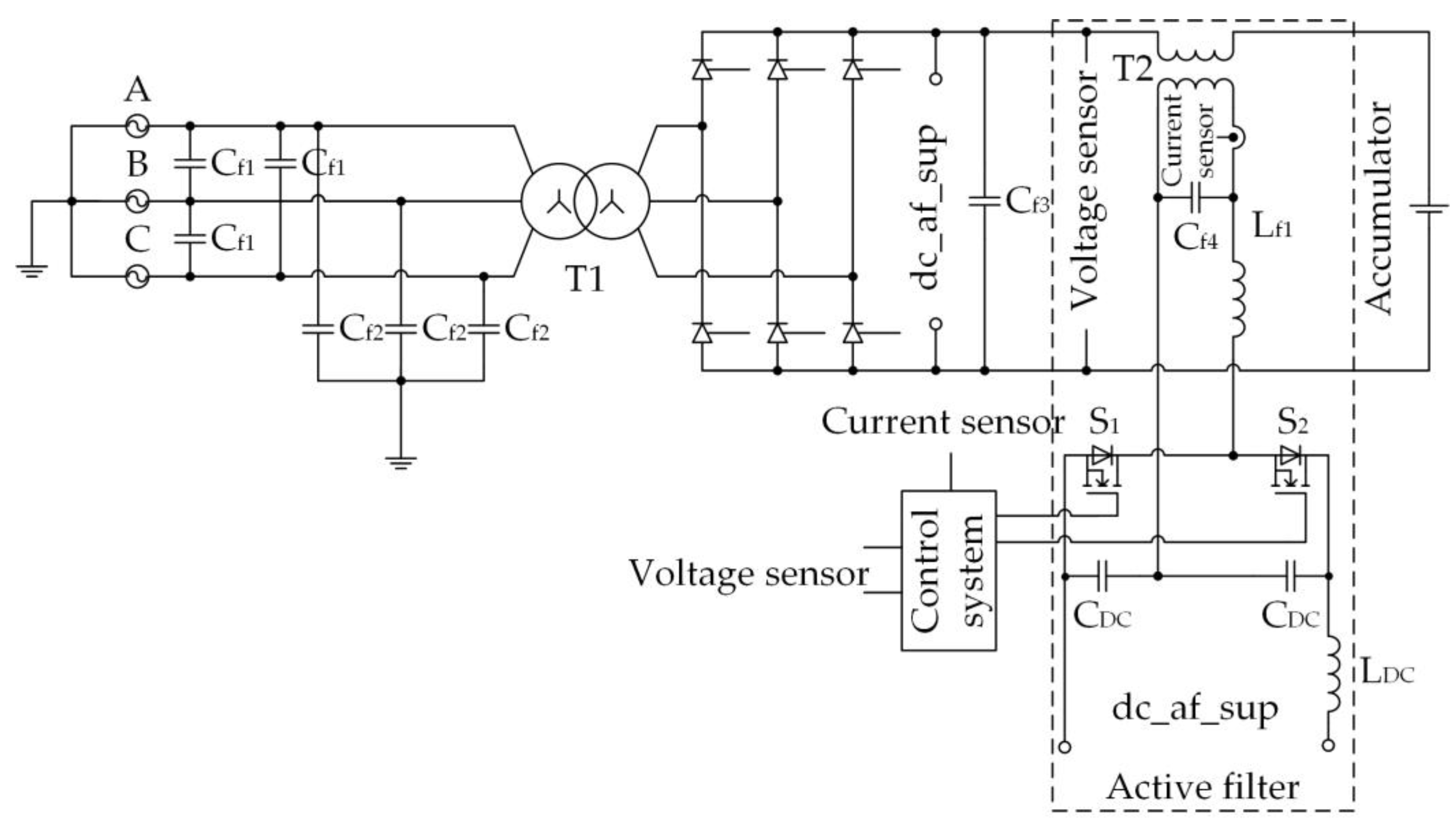
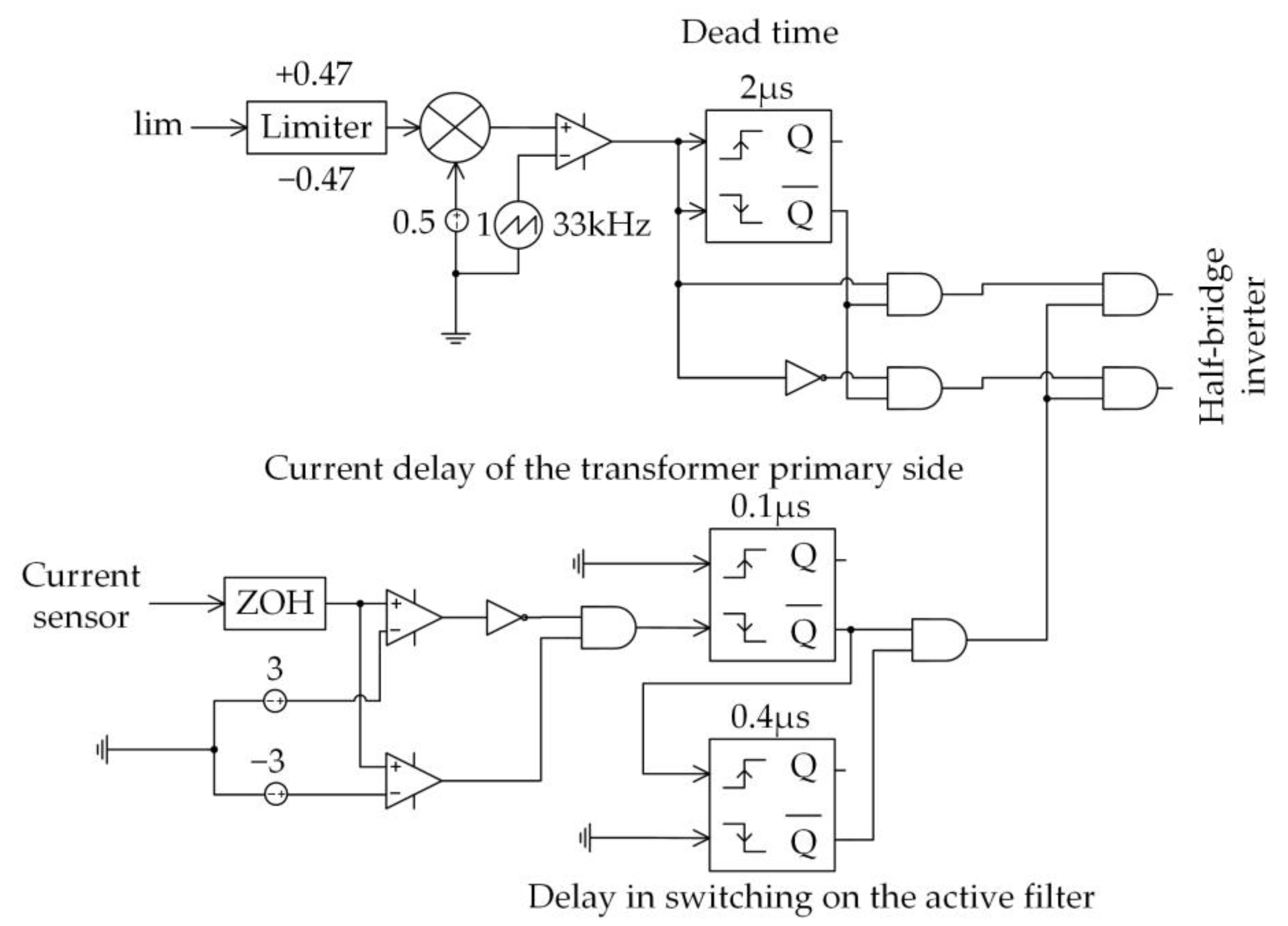
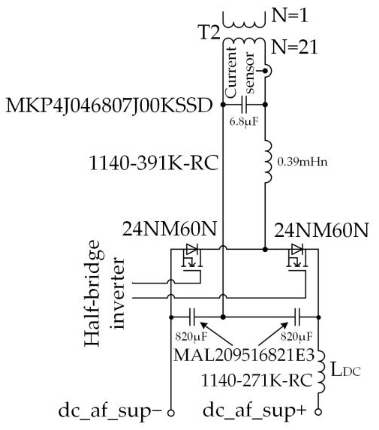
2. Active Filter Based on a Half-Bridge Circuit of a Single-Phase Voltage Inverter

Today, the quality of electrical energy is strictly regulated and often can lead to the failure of household and industrial equipment due to a poor-signal-level voltage or current. As an example of such a consumer, we can consider systems where the presence of an accumulator battery is required, which require high-quality currents and charging voltages, primarily currents. The use of high-capacity batteries affects more and more areas directly related to social spheres, which may include power supply systems for urban transport, uninterruptible power supply systems for municipal institutions, data banks and power supply systems for the aerospace industry. If in electric buses it is a source of driving force, then in hospitals and server stations the presence of a power source with rechargeable batteries will save data and even save lives in case of an emergency. The main advantage of batteries is multiple use, which is impossible without charging devices, but the service life of any rechargeable battery, especially a lithium-ion battery, which is one of the leaders in terms of capacity, depends on the shape and value of the current the battery is charged with.
Thus, in [38,39,40], pulsed boost, buck and buck–boost voltage regulators were proposed, providing a low level of current pulsations and, most importantly, the absence of low-frequency pulsation components: 100 Hz, 300 Hz. It has been proved that the presence of such pulsations significantly reduces battery life [41].
There are several ways to avoid this, as suggested in [38,39,40], such as using a converter as a source that will not have low-frequency harmonic components at the output and, finally, the installation of LC filters. It is possible to remove low-frequency pulsating components using multi-pulse rectifier circuits [24]. Unlike a single-phase rectifier built according to a bridge circuit (the frequency of rectified current pulsations is 100 Hz) and a two-half-period three-phase current circuit (the frequency of rectified current pulsations is 300 Hz), in a twelve-pulse rectifier circuit, the pulsation frequency will be twice as high—600 Hz. The use of such circuits in the power supply system requires a larger number of semiconductor power switches and the presence of several low-frequency power transformers with different connections of secondary windings, which will affect the reliability and cost of the device. If we are talking about high-power systems, the installation of reactive elements as low-pass filters will significantly increase the weight and size indicators; for example, a smoothing choke designed for a constant current of 300 A with an inductance of 170 μH will weigh 56 kg with dimensions of 306 × 230 × 235 mm3, whereas the converter for the same current will be less than 10 kg with dimensions of 155 × 280 × 215 mm3 [42]. Thus, the presence of a choke, including in a pulse converter, increases the dimensions of the power supply system by 2 times and increases the mass of the device by 5 times. Accordingly, in a high-power supply system with hundreds and thousands of kilowatts of power, the weight and size of the power choke will be very significant, currents through it can reach hundreds of amperes and the cross-section of wire will equal from 50 mm2 or more. At the same time, the number of winding turns can be several tens depending on the design of a choke.
An alternative version of the LC filter was proposed—a power active filter [43]. This is another converter, which is the source of the pulsation component, but opposite in phase present in the output signal of the rectifier. It is connected to the output circuit of the rectifier through a matching transformer with a small number of secondary winding turns, from one, which improves its weight and dimensions compared to the choke [44,45,46,47,48,49,50,51,52,53,54]. A single-phase inverter of the H-bridge type is used as a converter.
An active filter is proposed for the power supply system based on a monoblock type NRT 160.220 charging and rectifying device, where a half-bridge circuit of the single-phase voltage inverter is used as a compensator. Compared with pulse converters on transistors, a charging and rectifying device based on a thyristor rectifier will have a greater overload capacity.
Figure 1 shows a diagram of a charging and rectifying device with an active filter. To select the required compensation signal, it was necessary to develop a control system for a semi-bridge single-phase voltage inverter. Switches were regulated by pulse-width modulation, where a sawtooth signal with a frequency of 33 kHz was used as a reference signal, which is a multiple of the pulsation frequency (300 Hz). The modulating signal was a pulsation component, selected using a second-order Bessel filter and a low-pass filter (Figure 2).
The input of the Bessel filters and the low-pass filter (1) received a signal from the output of the rectifier “voltage sensor”. The signal at the output of the rectifier consists of a constant and a variable component, so it was necessary to filter out the constant component and save only the variable one. The signal will work as a modulating signal of the half-bridge voltage inverter control system. The Bessel filter in this work filtered an operating variable signal. The low-pass filter (2) was necessary to scale the signal to the requirements of the digital control system. At the output of the low-pass filter (1), the constant signal level was obtained along with the implementation of the auto-tuning function. It was required to obtain a modulating signal not exceeding 1 V in span. The output signal from the low-pass filter (2) was divided by the signal level from the output of the low-pass filter (1). Thus, the difference in the output voltage level from the rectifier of the charging and rectifying device was taken into account.
The current increases on the primary side of the transformer T2 due to the fact that the active filter with the charging and rectifying device is switched on instantly, or the output voltage of the charging and rectifying device is changed. It was decided to install a current sensor in the circuit of the transformer’s primary side that tracks its surge. The limit was fixed at ±1.5 A (after the LC filter choke) (Figure 3).
This solution is implemented in the block “current delay of the transformer primary side”. At the same time, the delay duration is 0.1 s. In addition, in the “delay in switching on the active filter” block, the active filter activation delay is 0.4 s. This ensures that the capacitors of the active filter are charged, while the transistors are turned off at this moment due to the prohibition on issuing control pulses. The dead time circuit provides a delay in the output of transistor control pulses; it is equal to 2 μs, preventing both switches of the half-bridge inverter from being switched on simultaneously.
The power unit consists of a half-bridge voltage inverter and a matching transformer T2 (Figure 4).
It is worth noting that the inverter of the active filter must be powered. Several solutions were considered, including the option proposed in [35], where an additional diode bridge connected to the input of a charging and rectifying device was installed as a DC source. It was decided to power the inverter from the output of the rectifier of the dc_af_sup charging and rectifying device. But in this case, when regulating the voltage of the rectifier of the charging and rectifying device, the supply voltage of the inverter would also change, which could negatively affect the value of the compensation signal. Thus, a tracking system for the value of the inverter supply voltage was required.
In [55], Mirzaee proposes a two-circuit closed control system, where both the input voltage of the active filter (with pulsation) and the output voltage from the matching transformer (without pulsation) are monitored. The principle of operation is similar to that offered in the proposed active filter. The pulsation component is also selected, which is compared with a high-frequency signal as a modulating signal. In this case, there is no monitoring of the output voltage, but a current feedback loop is added. It was possible to avoid an error in the output signal due to the sequential installation of a second-order Bessel high-pass filter and a low-pass filter (Figure 2). The presence of only a high-pass filter introduced a positive phase shift into the resulting modulating signal, which amplified the error between the compensating signal of the active filter and the output voltage of the rectifier. When the low-pass filter is installed in series with the high-pass filter, the phase shift is significantly reduced and the error in the output circuit of the active filter becomes minimal (Figure 5).
The filter calculation (low frequencies, high frequencies) was reduced to finding the nominal values of RC elements included in the filter on operational amplifiers:
R 40 C = f n / 2 π f c ,
where fn is the normalizing frequency equal to 1.274 Hz for the Bessel filter second-order, fc is the cutoff frequency, which is known, and in our case it is 20 Hz [56].
R 37 = R 38 ( 1 K ) ,
where K is the gain.
U o u t _ h i g h p a s s = U o f f s e t ( R 39 / R 39 + R 52 ) · ( 1 + R 37 / R 38 ) ,
where Uoffset is the upward offset voltage.
U o u t _ l o w p a s s ( 2 ) = U o u t _ h i g h p a s s · R 46 / R 47 ,
where Uout_low-pass(2) is the output of the low-pass filter, the scaled signal of the high-pass filter.
U o u t _ l o w p a s s ( 2 ) = E o f f s e t · R 46 / R 50 ,
where Eoffset is the downward offset voltage.
The calculation of the low-pass filter (1) is presented as follows:
-
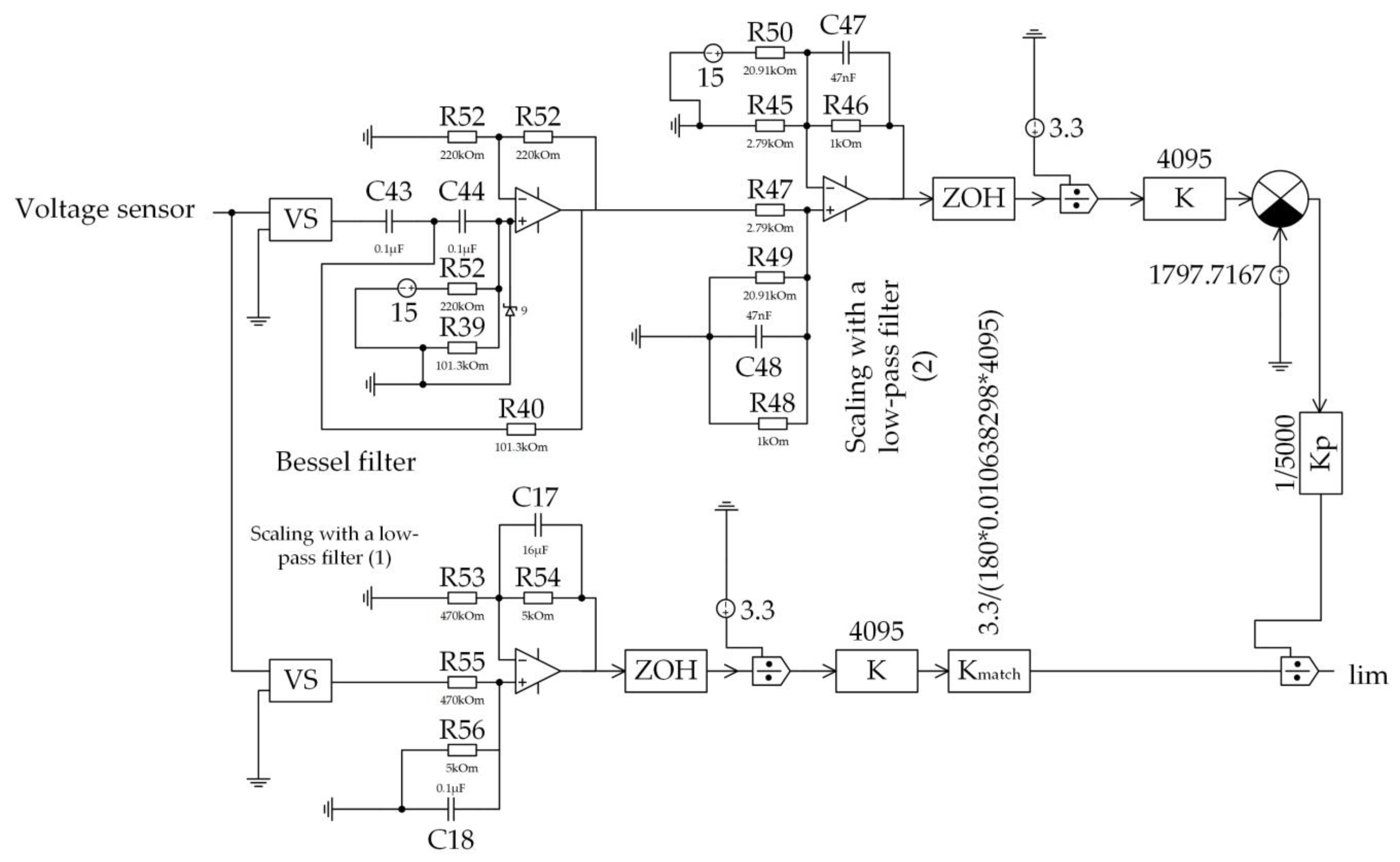
Determination of the resistor and capacitor values for the selected cutoff frequency, 2 Hz in our case:
R C = 1 / 2 π f c ,
-
Determination of the resistor and capacitor values for the required gain, selected based on the calculation that Uin is the input voltage equal to the maximum according to the technical specification (270 V), and Uout_op is the output voltage of the operational amplifier (≈3 V):
R 53 = R 54 / K .
In addition, the system has an adaptive coefficient that reacts to changes in the supply voltage of the active filter (from 180 V according to technical specification):
K m a t c h = 3.3 / ( 180 · K l o w p a s s ( 1 ) · 4095 ) .
During the power circuit calculation, the parameters of the transformer and LC elements were obtained, and transistors were selected (Table 1).

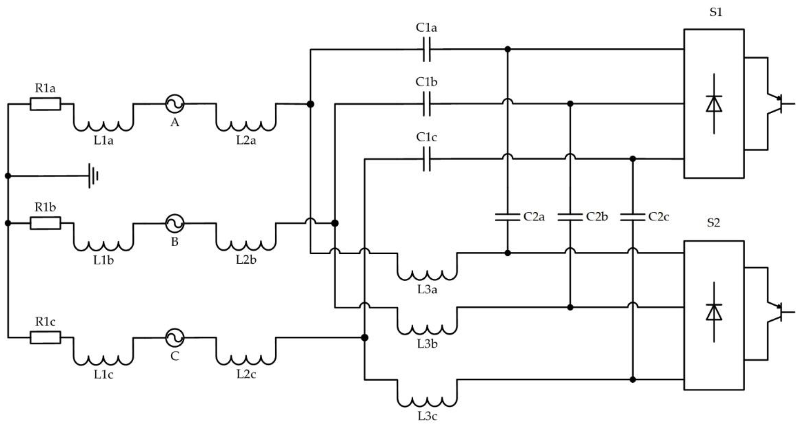
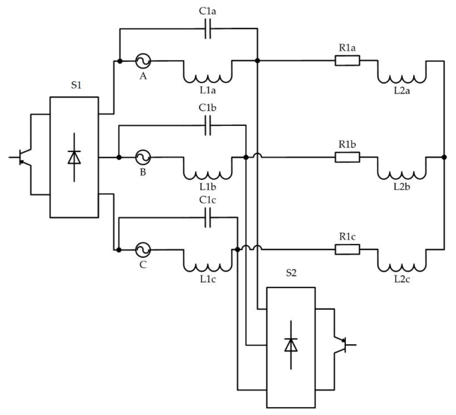
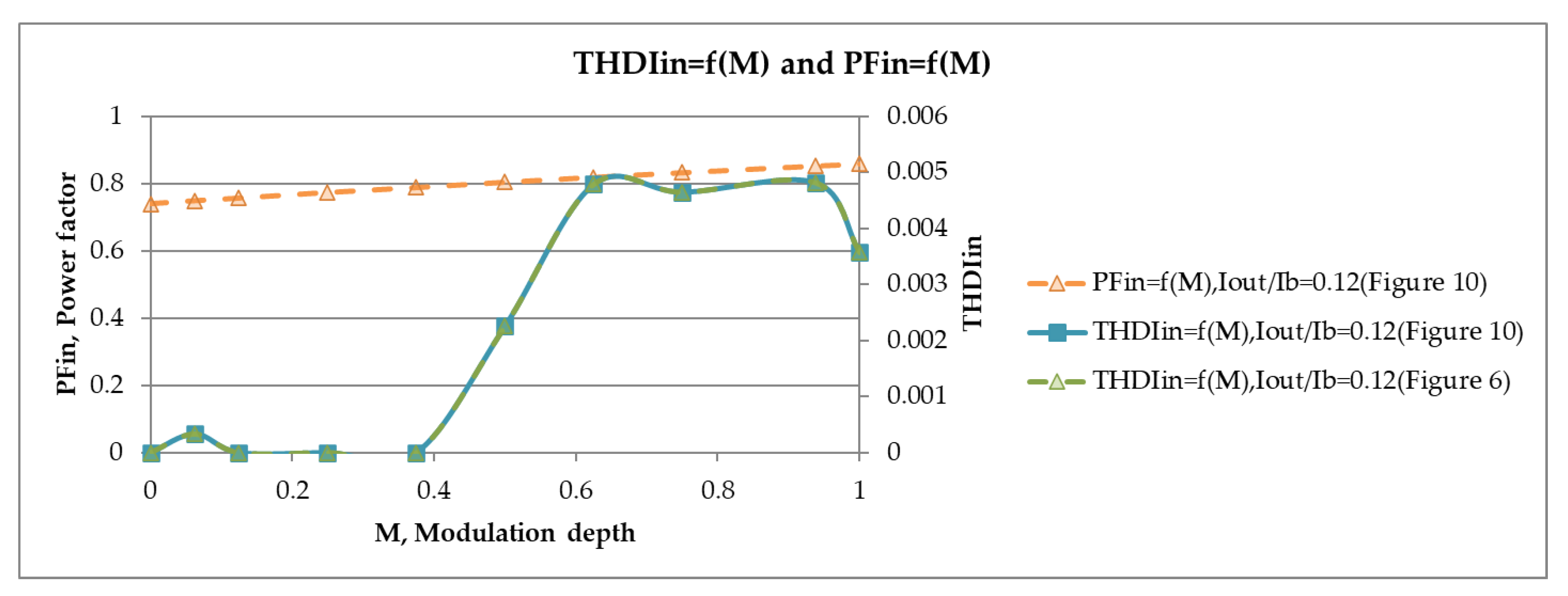
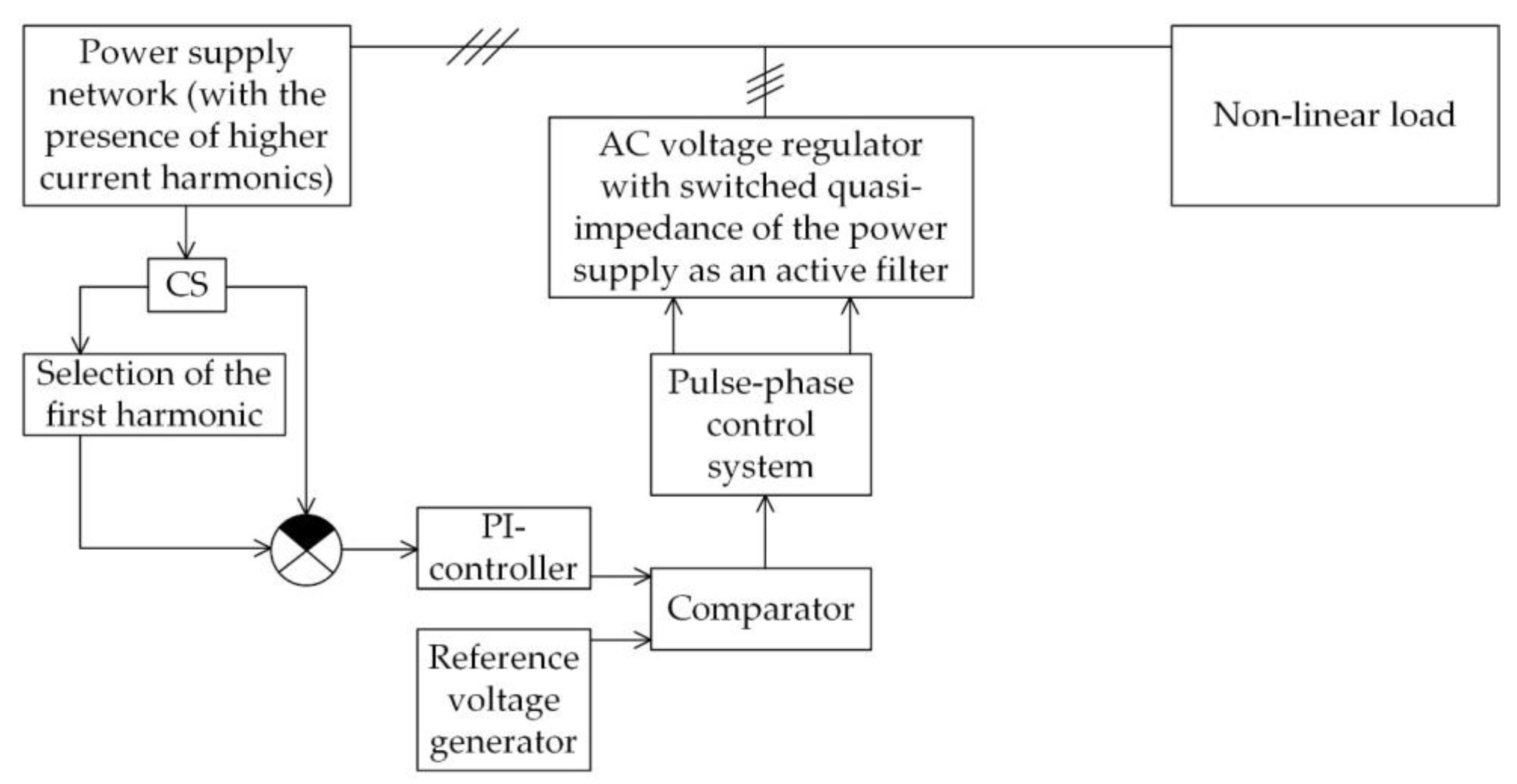
3. Active Filter Based on an AC Voltage Regulator

AC voltage regulators can be constructed using single-stage (direct) and multi-stage circuits. On the basis of single-stage AC-AC converters; AC voltage regulators; stabilizers; active harmonic filters; reactive power, voltage drop and flicker effect compensators; and symmetrical devices in multiphase networks as a combination of all these functions, an electrical energy quality “conditioner” is constructed.
For the successful construction of these devices, it is necessary to have effective single-stage AC voltage regulators. The well-known classical thyristor regulators with phase control are not suitable for solving these problems due to the distorted shapes of input and output currents and the delay in regulation associated with the properties of natural switching. In the middle of the 1990s, AC voltage transistor regulators with high-frequency controlled inductive–capacitive energy exchange appeared. They were characterized by almost sinusoidal shapes of input and output currents and good dynamics of their regulation [25,26,27,28]. The possibility of a transformerless increase in the output voltage relative to the input one in some types of regulators should be noted [25,26,27,28,29,30,31]. A set of such AC voltage regulators was obtained by appropriately adapting known circuits of DC-DC buck–boost regulators for operation in AC circuits [25,26,27,28,29,30,31,32,33,34,35].
The topologies of AC voltage regulators are being upgraded based on the following research directions: voltage stabilization, voltage regulation to nominal values and voltage increase with a gain greater than one. Recently, much attention has been paid to the quality of electrical energy. This in turn led to the development of existing AC-AC converters into devices for improving the quality of electrical energy, namely reactive power compensators, active filters, voltage drop compensators, etc. As a result, in addition to semiconductor elements, more reactive elements began to appear in the topologies of regulators. In this regard, it became necessary to evaluate AC voltage regulators from different points of view of efficiency. Let us first consider the quantitative factor of how many reactive and semiconductor elements they included. The balance between efficiency, reliability, dimensions and cost of systems has led to the development of several areas of construction of AC voltage regulators at once. The transformer version includes an AC voltage regulator with switchable cells and reactors. This converter allows you to compensate voltage drops and overvoltages. The regulator can generate different voltage levels, thereby suppressing voltage drops and overvoltages [57]. Also, this should include a unidirectional buck AC voltage regulator, and its modification is a bidirectional boost regulator. This converter can operate as a voltage drop compensator with a relatively wide compensation range. In this topology, it is assumed that there are eight IGBT switches in combination with a step-down transformer [14]. Despite all the advantages of such regulators, a large number of semiconductor switches affects both the efficiency and the cost of the system and also increases the share of kW/USD. If we also take into account the fact that such regulators can be used in three-phase networks, then this number of switches increases threefold. The dimensions of the system are mainly determined by the presence of reactive elements in the converters, which affects the weight and size parameters, and the proportion of kW/kg increases. There are also transformerless versions of AC voltage regulators; for example, a matrix converter has smaller filters. Its relative power can also be included in its advantages. Among the disadvantages of such a converter are the lack of the possibility of increasing the output voltage and the inability to compensate for the input reactive power [58]. Cascade H-bridge circuits allow for generating multi-level step voltages together with the voltage on the capacitors [10]. There are also AC-AC resonant converters with a high-frequency AC link. In the regulator, energy is transferred from the input to the output through the reactor L, which is charged with an input voltage and discharged to the output. The capacitor in the link creates a partial resonance, thereby performing soft switching. Also, the converter has a higher relative power and reliability in comparison with traditional PWM converters. In a resonant converter, the input power factor is equal to one, and it is possible to increase the voltage by a factor greater than one. Nevertheless, all these solutions have a large number of semiconductor switches, which increases their cost and makes them less effective in this regard. But the absence or small number of reactive elements has a positive effect on the weight and size indicators. Also, the improvement of weight and size indicators can be achieved using high-frequency transformers. Single-stage AC voltage regulators, for example, include AC-AC regulators with soft switching, but in this scheme, there is a fairly large number of AC switches. The circuit, in this regard, has large losses when keys are switching, but due to the use of soft switching, they are significantly reduced [59]. The three-phase version of the AC voltage regulator with soft switching can be used at both small and medium power. In addition, this converter has a high input power factor and has the ability of bidirectional energy flow with the necessary amplitude and frequency control [60]. Two-stage AC voltage regulators with a high-frequency transformer are also found in distribution systems [61,62]. Two-stage regulators can operate at high output power along with low losses in power circuits due to the switching of one switch at each clock cycle of the circuit.
Existing transistor AC voltage regulators, buck–boost AC-AC converters, with and without a transformer, with a high-frequency link, with a DC link and H-bridges have a number of disadvantages, mainly the presence of a large number of reactive and semiconductor elements. This also includes the inability to use them in general industrial networks, as well as the inability to increase the voltage by a factor greater than one. In this regard, an assessment can also be made from the point of view of the voltage increase coefficient. This, in turn, is suitable for a class of AC-AC-type converters, called electronic transformers. Transformerless matrix converters have a voltage increase coefficient that is not more than one. It was proposed to include a volt-additional source of reactive voltage in series between the output of the converter and the load to increase the coefficient [63]. For this goal, a single-phase bridge voltage inverter without a power source in the DC link is used. Another way to increase the voltage boost coefficient of the matrix converter and the voltage inverter included in its structure is associated with the modification of the control method. The method is based on the cyclic control in every sixth part of the output voltage period only by switches of its two phases, leaving switches of the third phase permanently conducting. With this method, the output of the first harmonic of the voltage is increased by 15%. There is also a way to increase the boost factor by combining pulse-width modulation and pulse-width regulation [64,65]. In this case, the output voltage will be formed by pulse-width regulation pulses, which, with full modulation, will lead to an increase in the first harmonic by 28%. Another way to change the voltage increase coefficient is to solve the problem of combining a matrix converter with a boost AC voltage regulator [66,67]. Such a scheme requires an input LC filter. The scheme of a one-phase matrix buck–boost converter is formed from a bridge matrix converter and a Ćuk AC voltage regulator [68]. Another buck–boost matrix converter with a continuous input current is formed from a Ćuk AC voltage regulator and a zero-matrix converter [69]. Among the disadvantages of matrix converters are the large number of switches and the complexity of control algorithms that can be selected. An alternative solution to electronic transformers can be called AC voltage regulators, which have significantly simpler circuits and simple control algorithms. AC voltage regulators have been proposed based on the introduction of a volt-additive using a high-frequency conversion [70]. The input and output currents of such a regulator are of high quality. There are also multi-cell high-voltage regulators using AC/DC–high-frequency DC/AC–high-frequency AC/AC–AC/DC–DC/AC in each channel. They provide galvanic isolation and small weight and size indicators at a high frequency in the intermediate link. Another direction of boost high-voltage AC voltage regulators is based on the Arkadiev–Marx concept of a boost DC voltage converter. Here, at a high frequency, the capacitors are first switched on in parallel with the supply network and charged to the current value of the AC voltage and then switched on in series and feed the output circuit [71].
The construction of an active filter is possible on the basis of single-stage AC-AC regulators with switching quasi-impedance of the power supply with a high frequency [72,73,74].
Some circuits require separated phases of the power supply (Figure 6, Figure 7, Figure 8 and Figure 9) or loads (Figure 10).
Each scheme can be divided into three parts. The first part is a power supply with its own inductive reactance; the second part is the load circuit of a reactor and active resistance connected in series; and the third part is everything else from reactors, capacitors and switches between the first and second parts. The purpose of the circuitry of the third part is to ensure the switching of inductive–capacitive reactance parameters between the first and second parts, which is an external quasi-impedance of the source. At the same time, it avoids surges of reactor currents and capacitor voltages.
So, you can evaluate the existing and proposed types of AC-AC converters (Table 2).
An extension of the direct method for the energy parameter calculation of the converter (Figure 9) was constructed for its model with variable parameters, leading to differential equations with periodic discontinuous coefficients. After their algebraization [24], we obtain the equations in matrix form for the first harmonics of the variables in (9):
0 R 1 0 1 ω L 1 ψ sin ω L 2 0 0 0 0 1 0 ω L 1 0 0 0 1 0 0 0 0 0 ω C 1 ω C 2 ψ sin 1 1 0 0 0 0 ω C 1 0 ω L 1 ψ cos ω L 2 0 0 0 R 1 0 1 ω L 1 0 0 0 0 0 1 0 0 0 ω C 1 ω C 2 ψ cos 1 0 0 0 0 0 ω C 1 0 1 1 0 0 · I 1 ( 1 ) a I 2 ( 1 ) a U C 1 ( 1 ) a U C 2 ( 1 ) a I 1 ( 1 ) r I 2 ( 1 ) r U C 1 ( 1 ) r U C 2 ( 1 ) r = U 1 ( 1 ) a ψ sin U 1 ( 1 ) a 0 0 0 0 0 0 ,
where ψ is the switching function of switches.
Regulators for comparison were modeled in the PSIM program with ideal parameters of the elements. The control characteristics for a number of regulators are shown in Figure 11; the load characteristics are shown in Figure 12; and the dependences of the input power factor, THD, on the modulation depth are given in Figure 13.
The efficiency of the proposed regulators can be considered from two points of view: the quality of the current and the quality of the voltage. This estimate is given to us by the THD. Some of the circuits were evaluated earlier using the current THD; this research was carried out experimentally, and it is also worth noting that this assessment allows us to implement the method of algebraization of differential equations (ADE), which was mentioned earlier. To determine the THD, it was necessary to determine the magnitude of the first harmonic of the current and the higher harmonics of the current. To do this, one phase of an AC voltage regulator with a switched quasi-impedance was analyzed, and a system of equations for similar circuits was compiled, as shown in Figure 7. The resulting matrix has the following form:
0 R 1 1 ω L 1 ψ sin ω L 2 0 0 0 1 ω L 1 0 0 1 1 ψ sin 0 0 0 ω C 1 ω L 1 ψ cos ω L 2 0 0 R 1 1 ω L 1 0 0 0 0 1 0 0 ω C 1 1 1 ψ cos 0 · I 1 ( 1 ) a I 2 ( 1 ) a U C 1 ( 1 ) a I 1 ( 1 ) r I 2 ( 1 ) r U C 1 ( 1 ) r = U 1 ( 1 ) a ψ sin U 1 ( 1 ) a 0 0 0 0 ,
where the determining factor of the harmonic component we are looking for is the switching function ψ.
So, to determine the components by the higher harmonics, we use the following expression:
ψ = 1 M + n = 1 1 π n sin 2 π n 1 M · cos 2 π n f t 1 π n cos 2 π n 1 M 1 · sin 2 π n f t ,
where n is the harmonic order.
In turn, an efficiency assessment was performed for the above schemes. It is worth noting that there is a method for calculating the efficiency of semiconductor converters [75,76]. We have evaluated static and dynamic losses in semiconductor switches. We took 2 kW for the base power, while the losses in a simple circuit of the buck–boost AC voltage regulator with a switched quasi-impedance of the power supply amounted to 80 W. In the AC voltage regulator with a switched quasi-impedance of the power supply, the losses amounted to 40 W. This can be explained by the circuitry of converters, where in the case of simple circuits of the buck–boost AC voltage regulator with a switched quasi-impedance of the power supply, more reactive elements are used.
Thus, data were obtained to determine the harmonic coefficient obtained theoretically and in the PSIM experiment, as well as the efficiency of regulators (Table 3).
A block diagram of the use of this type of regulator as an active filter is shown in Figure 14. To simulate the presence of high-frequency components in the network current, a rectifier was used as a load.
The direct connection of such a regulator is impossible without a closed-loop control algorithm. Figure 15 shows the control system of such a system.
As in an active filter based on a voltage inverter, compensation of the high-frequency component of the current occurs due to its introduction in the opposite phase, which can be obtained due to the LC circuit of the regulator. The current and voltage waveforms in the PSIM program before compensation are shown in Figure 16. The compensated signal is shown in Figure 17.
The first harmonic of the current signal was removed; its filtering could be carried out through a digital low-pass filter [76]. The filter parameters were calculated using the impulse response using the Blackman function:
w n = 0.42 0.5 · cos 2 π n N 1 + 0.08 · cos 4 π n N 1 ,
where N is the number of coefficients.
The parameters of the PI controller are calculated in such a way that, with the known parameters of all other elements of the system, the required quality of its response to the control and disturbing effects is ensured.
During the calculation, the proportional coefficient and the integration time were determined to be  K = 1.67  and  T i = 0.0334   s  [77].
A sawtooth signal with a frequency of 8 kHz was chosen as the reference voltage generator.

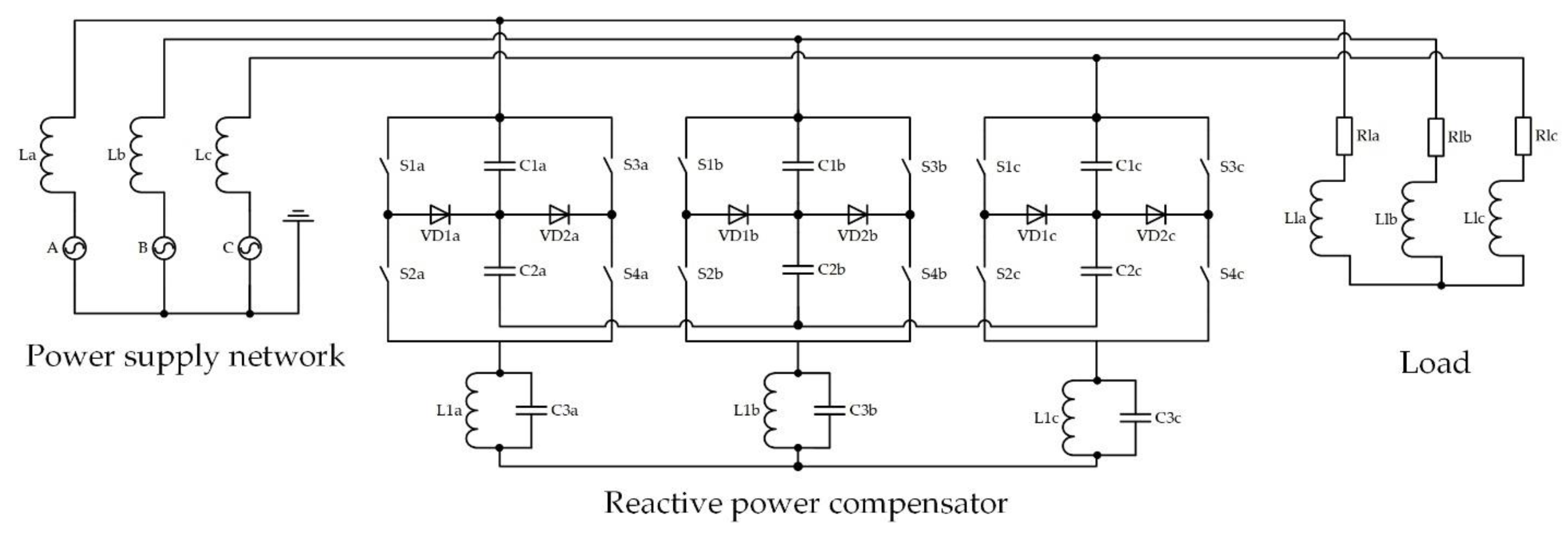
4. Reactive Power Compensator Based on an AC Voltage Regulator

A multi-zone AC voltage regulator was proposed [78], the main function of which was to soft start an induction motor. This solution has been adapted to the possibility of compensating reactive power in the input signal. The proposed system is shown in Figure 18.
When using a multi-zone AC voltage regulator, the input shift of reactive power is completely eliminated due to the presence of capacitive power. Its presence is due to the regulation of the output voltage. Reactive power can be eliminated by using the method of pulse-width regulation of the output voltage while remaining in phase with the supply voltage (Figure 19).
The presence of a current shift with an active inductive load, which can also be provided by an induction motor, is shown in Figure 20. The compensation algorithm is shown in Figure 21. The compensation algorithm also required signal phase tracking; this could be implemented in a closed system. The rectification unit is an uncontrolled rectifier made according to a bridge circuit, at the output of which a filter is connected. The filter is a capacitor, the capacitance of which is calculated as
C f = 10 × 0.02 q m 2 · R d
with a tenfold excess of the load signal time constant over the pulsation period and was  C f = 2 × 10 6   F , with a current from the current sensor equal to 5 mA.
The parameters of the PI controller are calculated in such a way that, with the known parameters of all other elements of the system, the required quality of its response to the control and disturbing effects is ensured.
During the calculation, the proportional coefficient and the integration time were determined to be  K = 2.857  and  T i = 0.0124   s  [77].
The reference voltage generator is the same sawtooth signal as in the previous section, the frequency of which depends on the selected power switches, in this case 8 kHz.

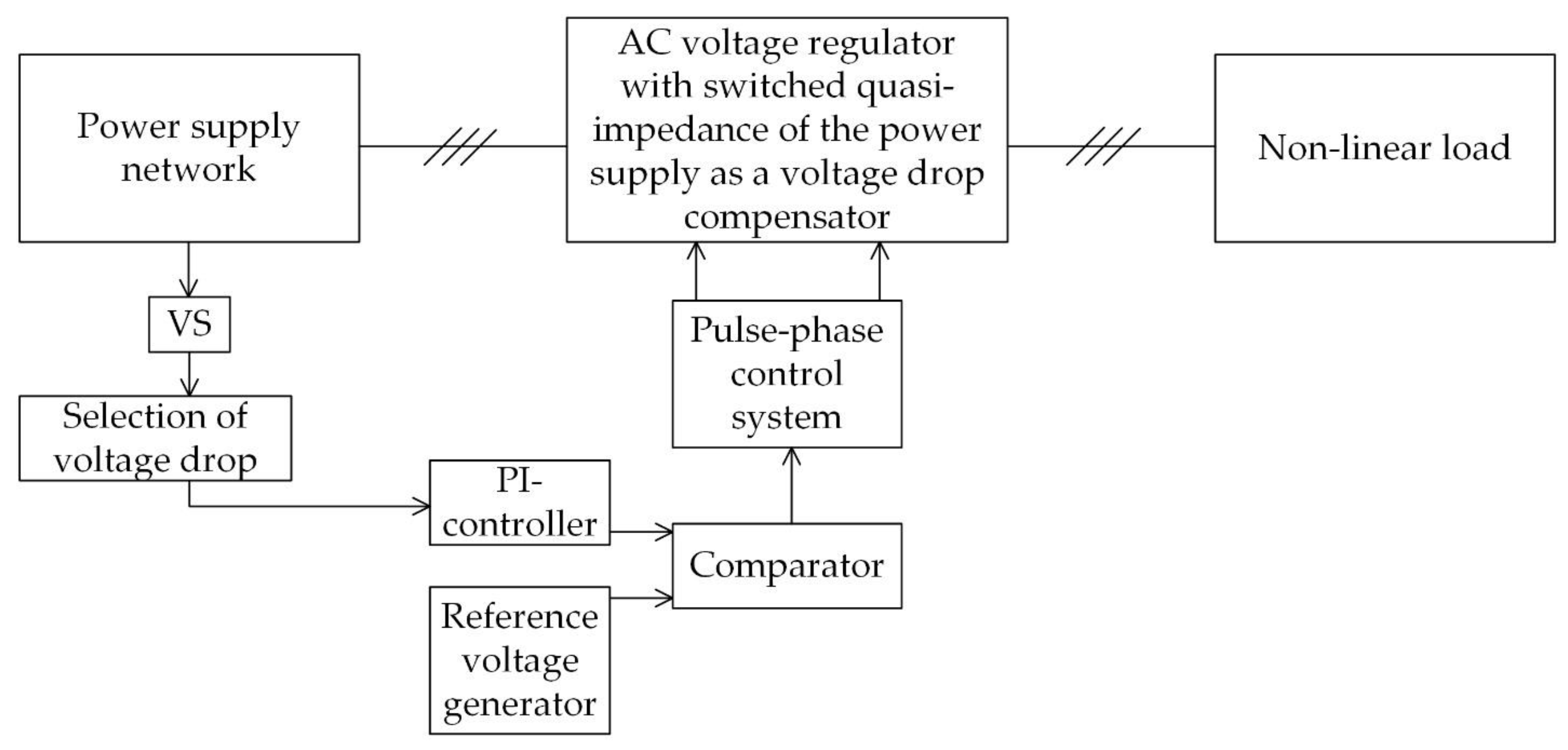
5. Voltage Drop Compensator Based on an AC Voltage Regulator

In supply voltage drops, appliances may malfunction, even leading to their failure. This circumstance requires the presence of a compensator.
A drop is considered to be a voltage drop below 0.9 Unom, followed by a voltage restoration to the nominal level or close to it after a period of time from ten milliseconds to several tens of seconds.
You can use an AC voltage regulator as a voltage drop compensator, as shown in Figure 8. This type of regulator has a full range of regulation and allows you to obtain increased output voltage with a full modulation depth of up to 1.4 of input voltage. This can be done by monitoring the network voltage level; in case of a drop, the regulator begins to operate in the voltage increase mode. The block diagram of the control system is shown in Figure 22.
In the drop selection unit, when the voltage amplitude decreases, fixation occurs; for example, in the case of using a digital control system, data are recorded in a microcontroller. It records the previous values of the signal, and then the current signal is subtracted from the stored previous one, thereby fixing the drop, which is then fed in the opposite phase.
The method presented in [77] was used for PI regulator calculating, in which the parameters of the object of regulation are calculated; in particular, the gain values are calculated, along with the parameters of the PI link itself, one of which is the integration time. According to the results of the calculation, the transmission coefficient and the integration time were determined to be  K = 1.18  and  T i = 0.079   s .
The reference voltage generator is a sawtooth signal with a frequency of 8 kHz.

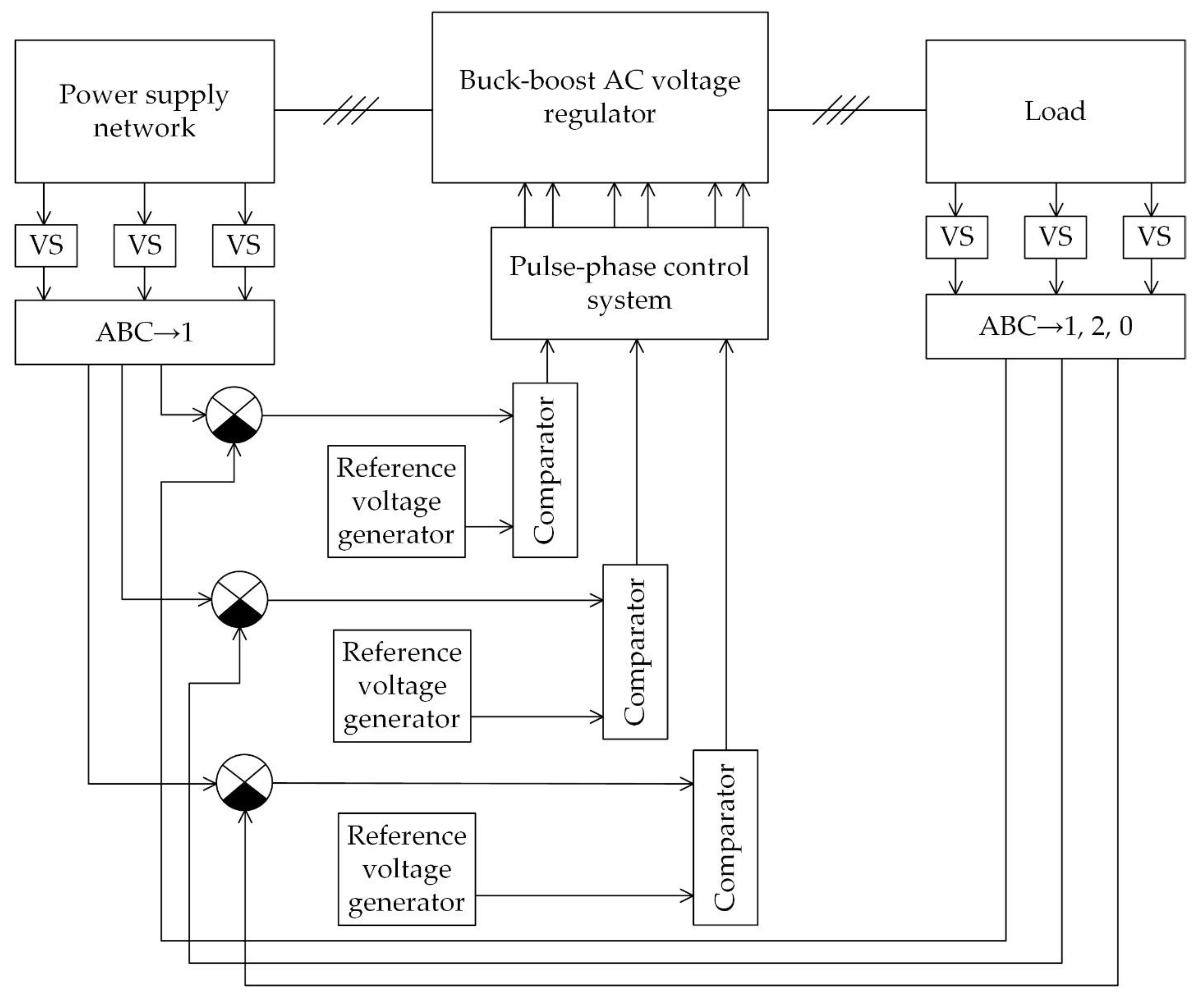
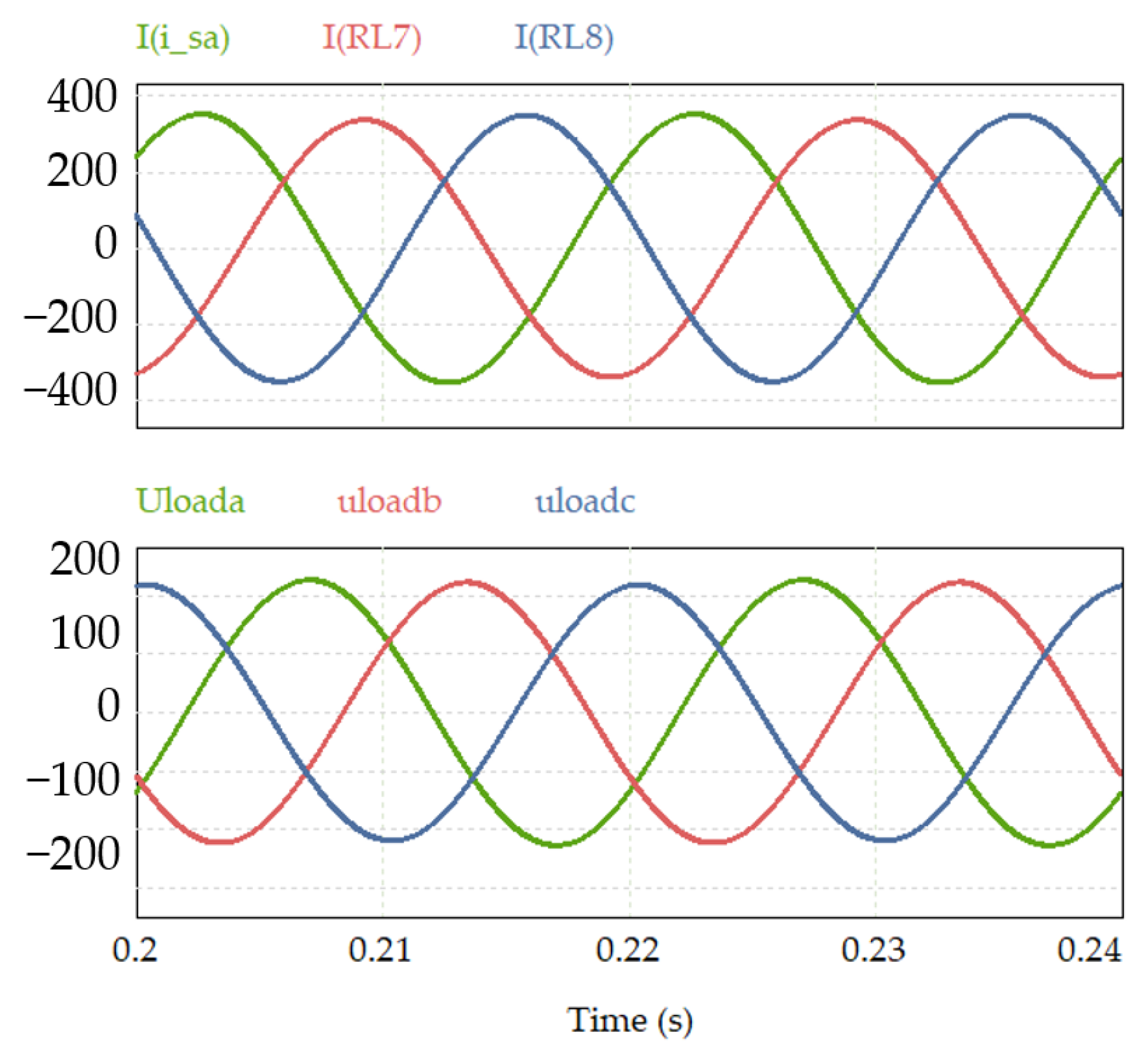
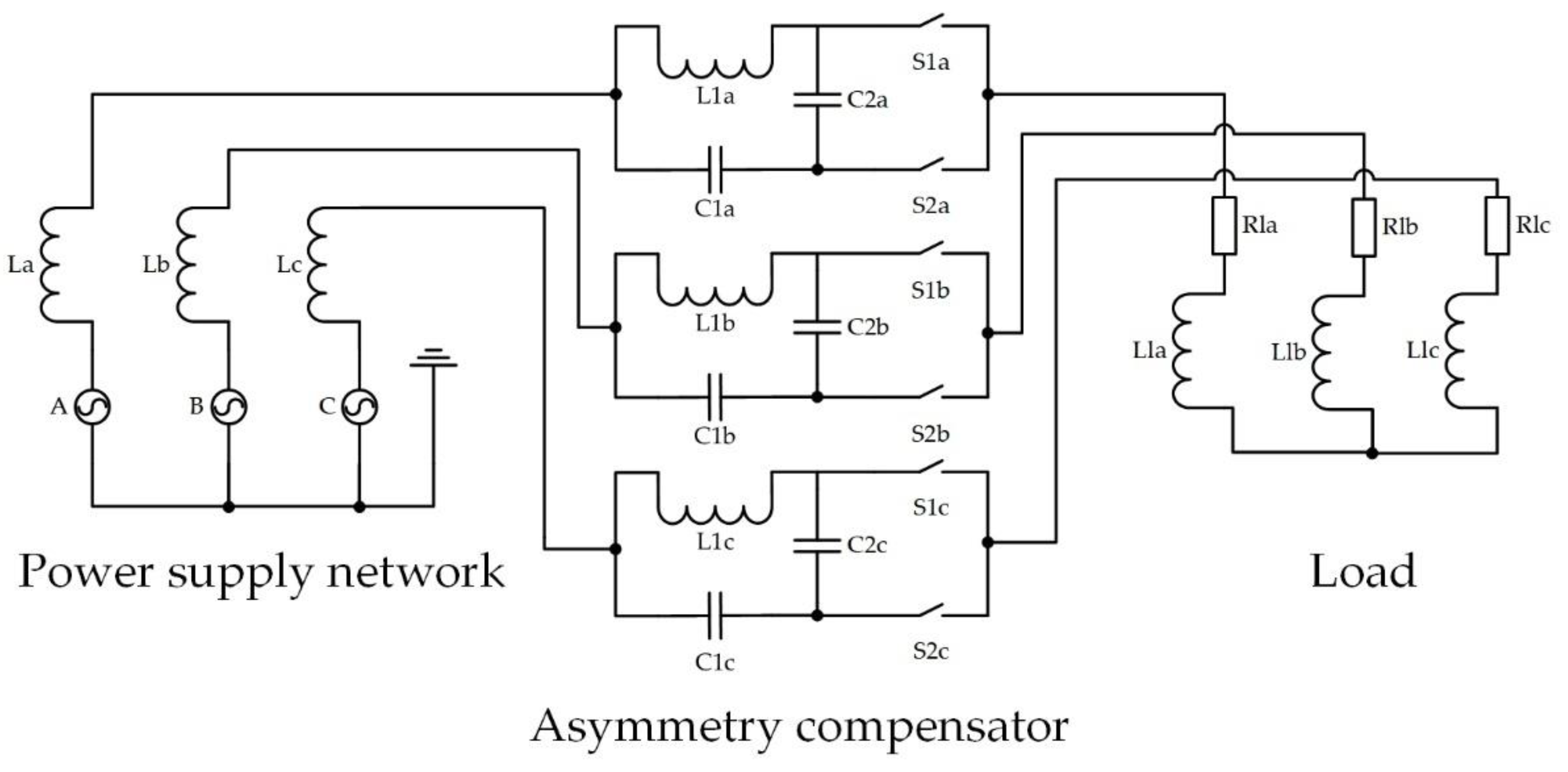
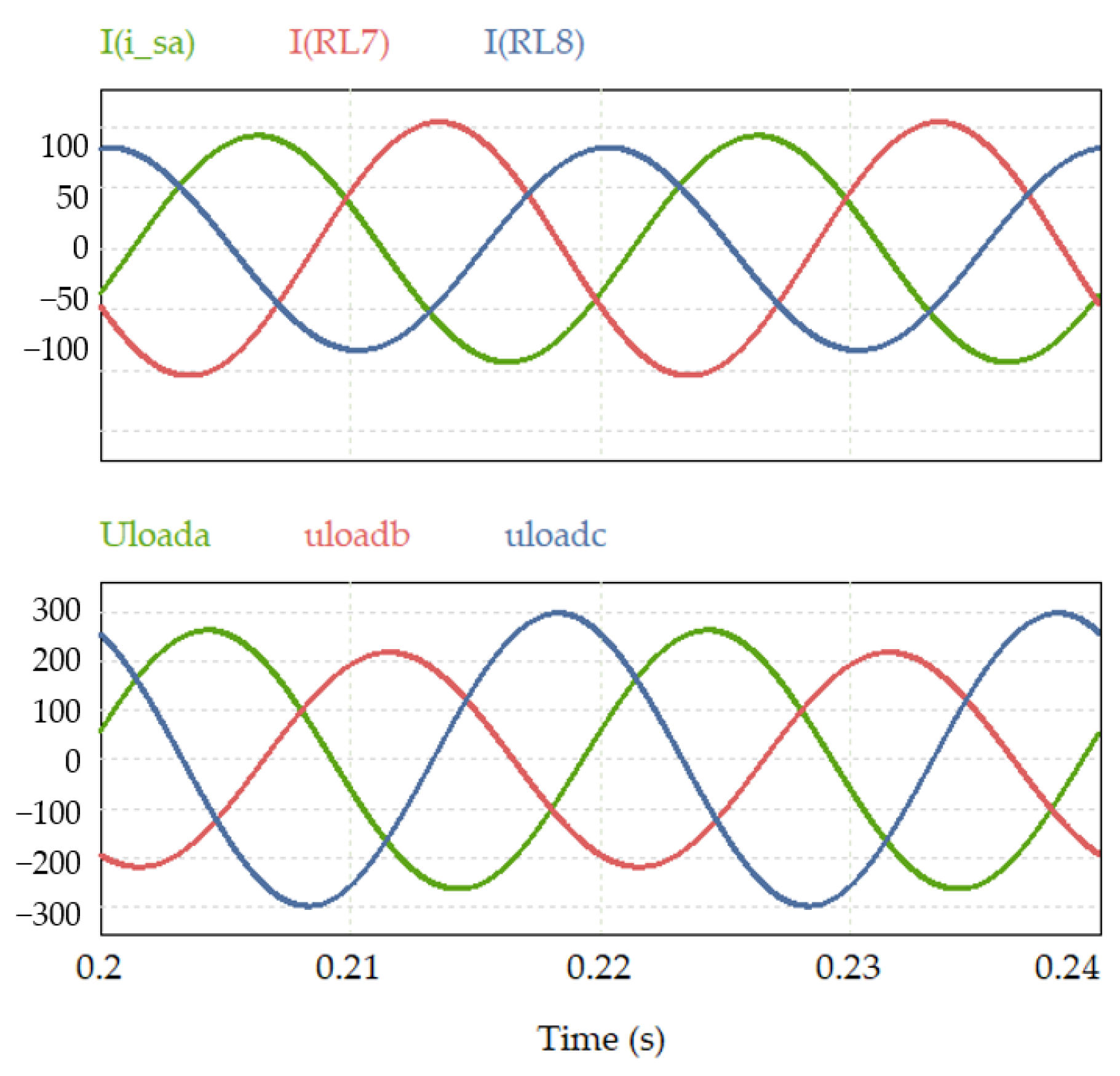
6. An Asymmetry Compensator Based on an AC Voltage Regulator

To eliminate the negative impact of powerful nonlinear loads on a network, it is necessary to use an asymmetry compensator, which can be used as a buck–boost AC voltage regulator [72] (Figure 23). The control system of such a compensator is shown in Figure 24.
Unbalanced voltage can be compensated using the control system. The signal will be received from the load voltage sensors and converted into a forward, reverse and zero sequence. Then, the error will be calculated, which will affect the magnitude of the received signal when converting the input voltage to a direct sequence signal. The reference voltage generator is a sawtooth signal with a frequency of 8 kHz.
Voltage diagrams before compensation are shown in Figure 25, and voltage diagrams after compensation of asymmetry are shown in Figure 26. At different loads, the phase voltage will be different, as can be seen in Figure 25. The compensation result is shown in Figure 26, where all three phase voltages are symmetrical.

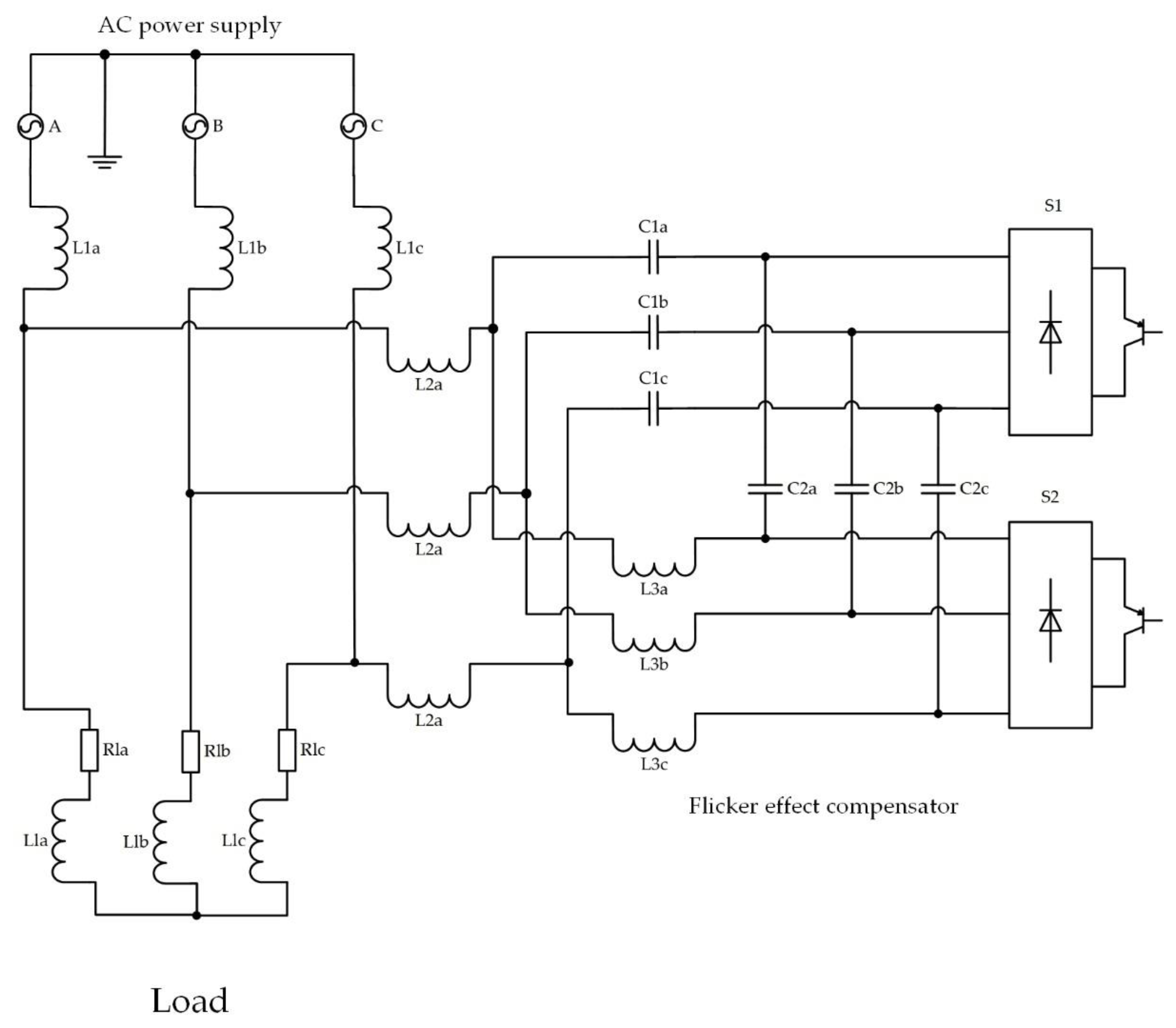
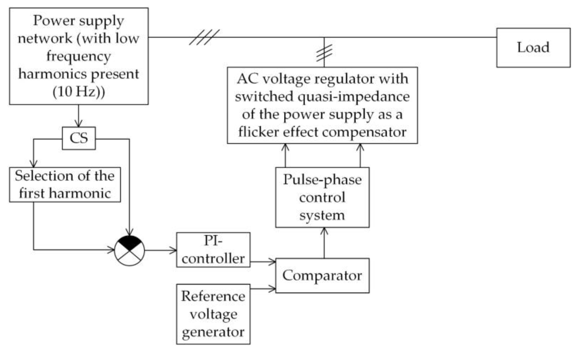
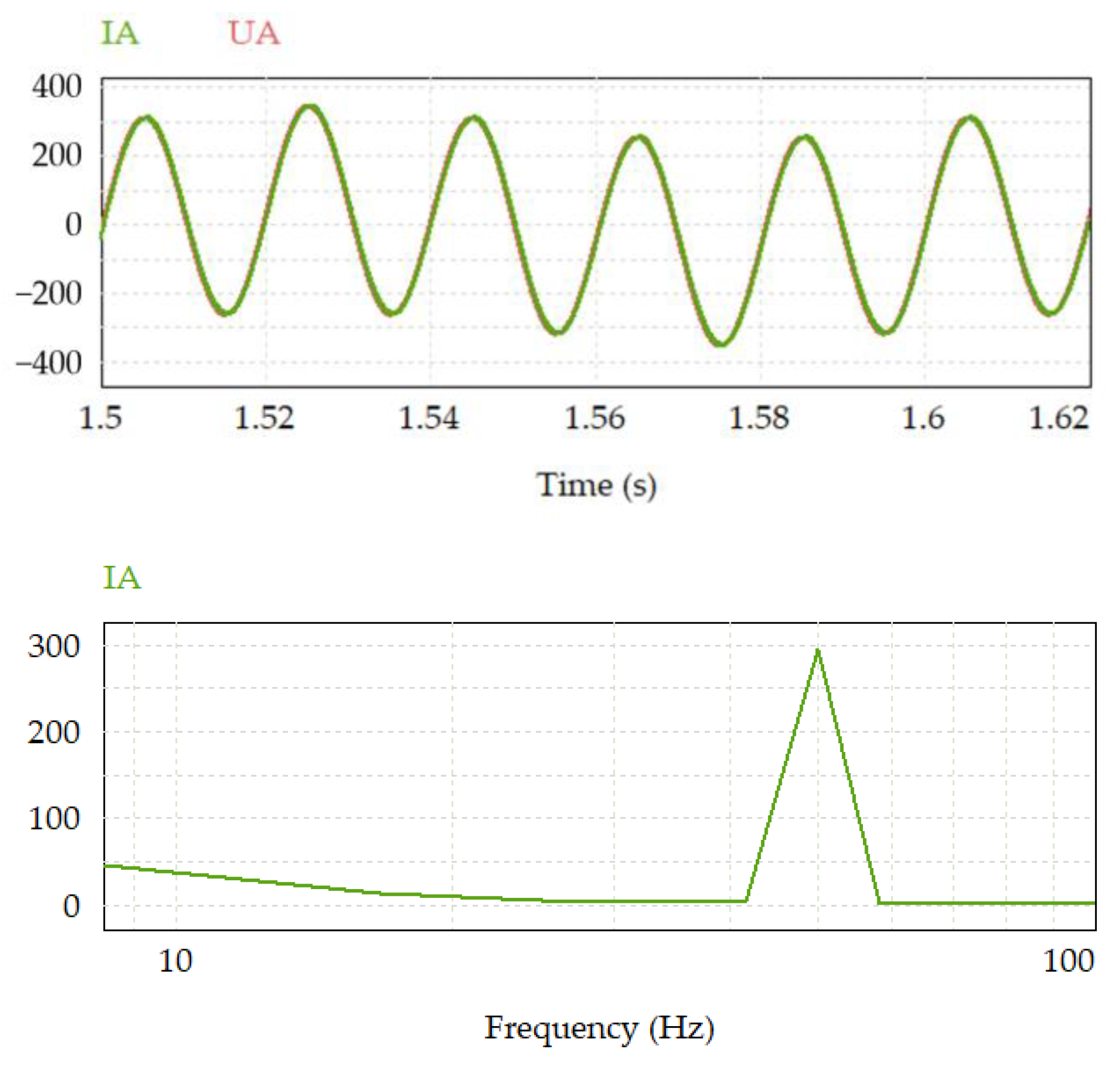
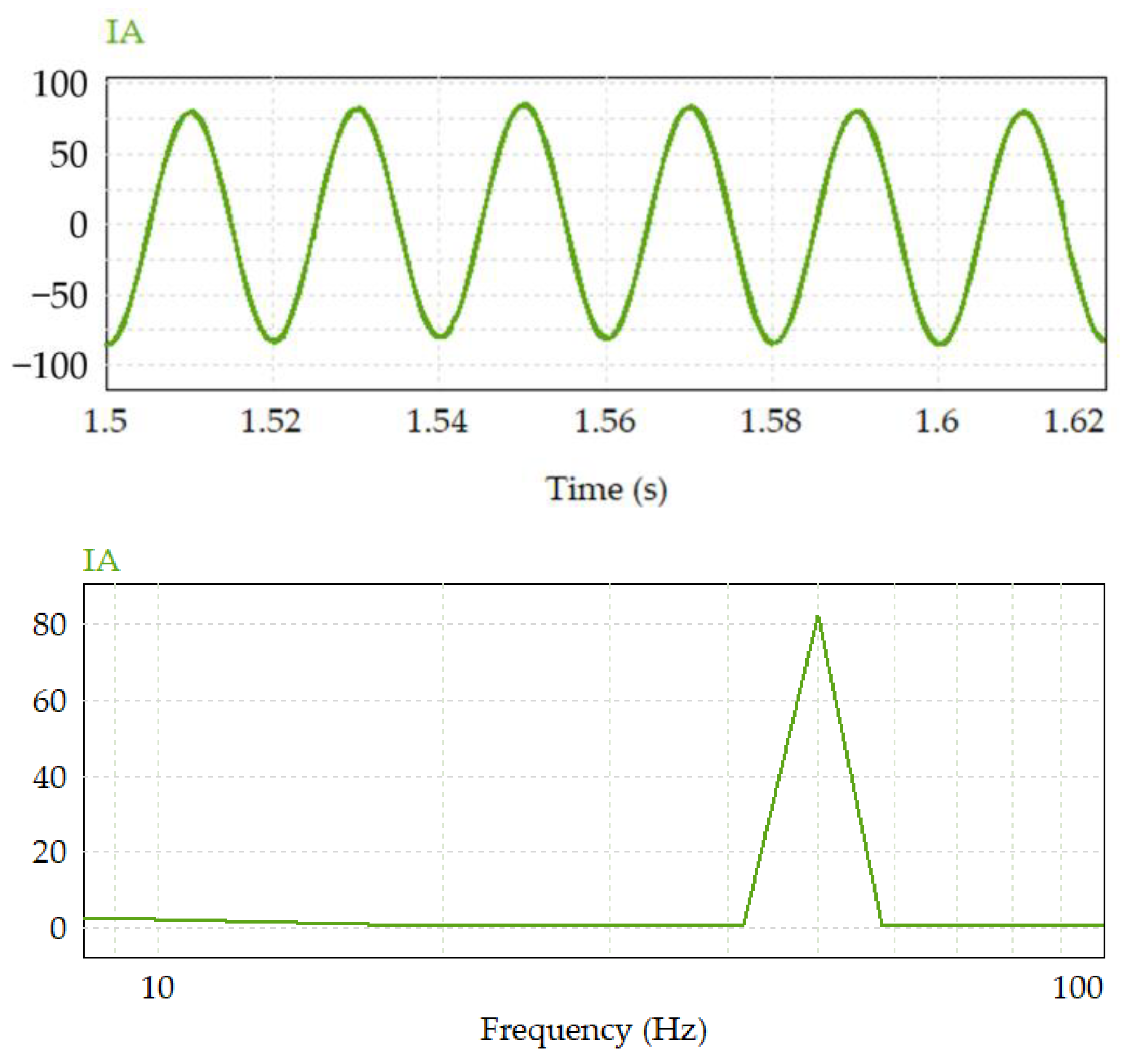
7. A Flicker Effect Compensator Based on an AC Voltage Regulator

Figure 27 shows a compensator circuit containing an AC voltage regulator. The flicker effect is the so-called flicker of lighting, felt by a person and caused by low-frequency fluctuations in the voltage level, for example, up to 10 Hz. Figure 28 shows the control system for an AC voltage regulator that performs the function of a flicker effect compensator.
The first harmonic selection unit is presented in the form of a digital low-pass filter [79]. To calculate the filter parameters, the ideal and real impulse responses are calculated, for which it is necessary to use the Blackman function.
As noted earlier, the parameters of the PI controller are calculated in such a way that, with the known parameters of all other system elements, the required quality of its response to the control and disturbing influences is ensured.
During the calculation, the proportional coefficient and the integration time were determined to be  K = 1.67  and  T i = 0.0334   s  [77].
The reference voltage generator is a sawtooth signal with a frequency of 8 kHz.
This regulator can work as a flicker compensator, suppressing low-frequency harmonics that are present in the supply network (Figure 29).
The compensation result is shown in Figure 30. Suppression of harmonics with a frequency of 10 Hz was achieved by adding these harmonics into the control signal in the opposite phase, thereby compensating for the presence of these harmonics in the system input voltage.

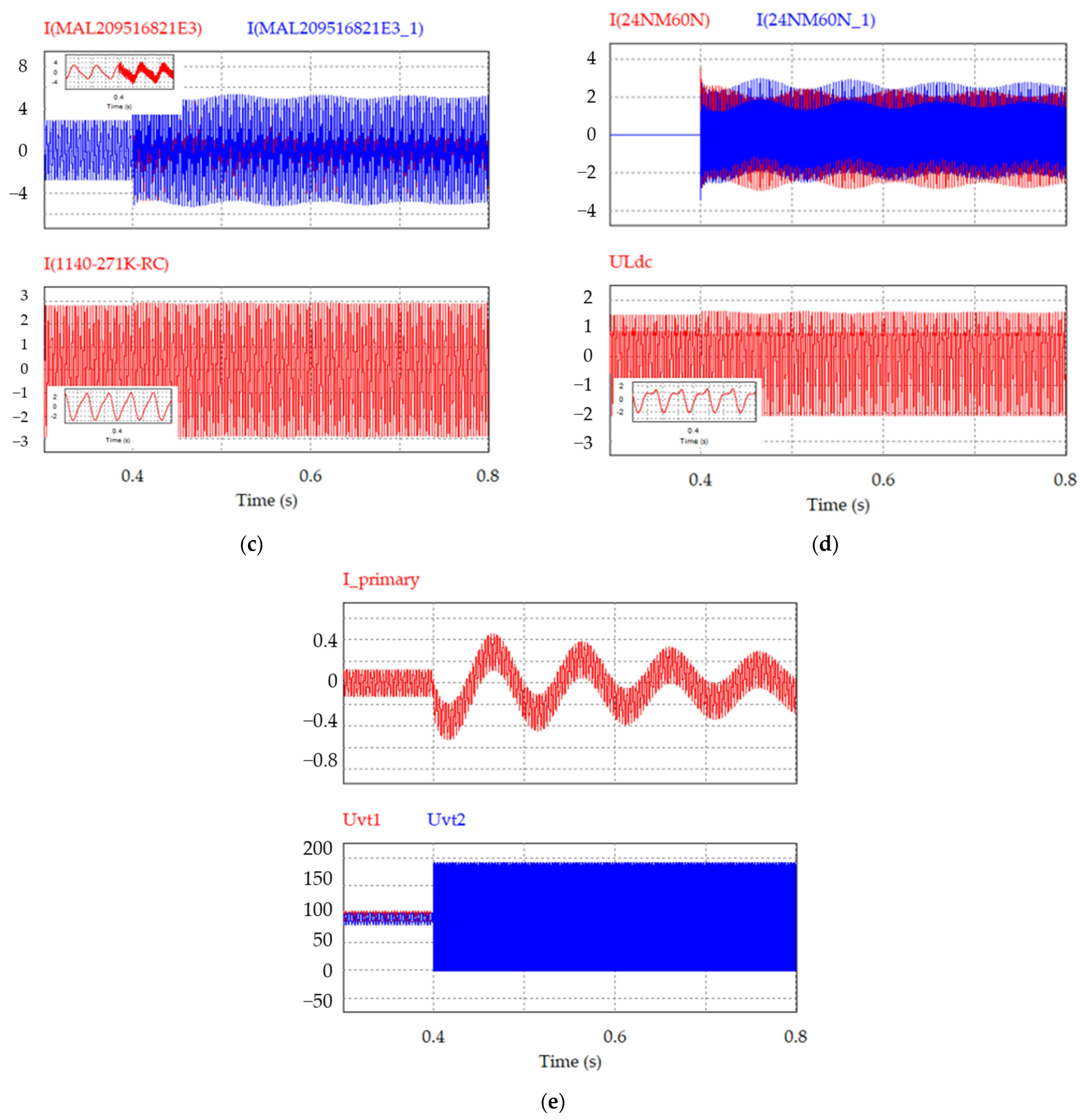
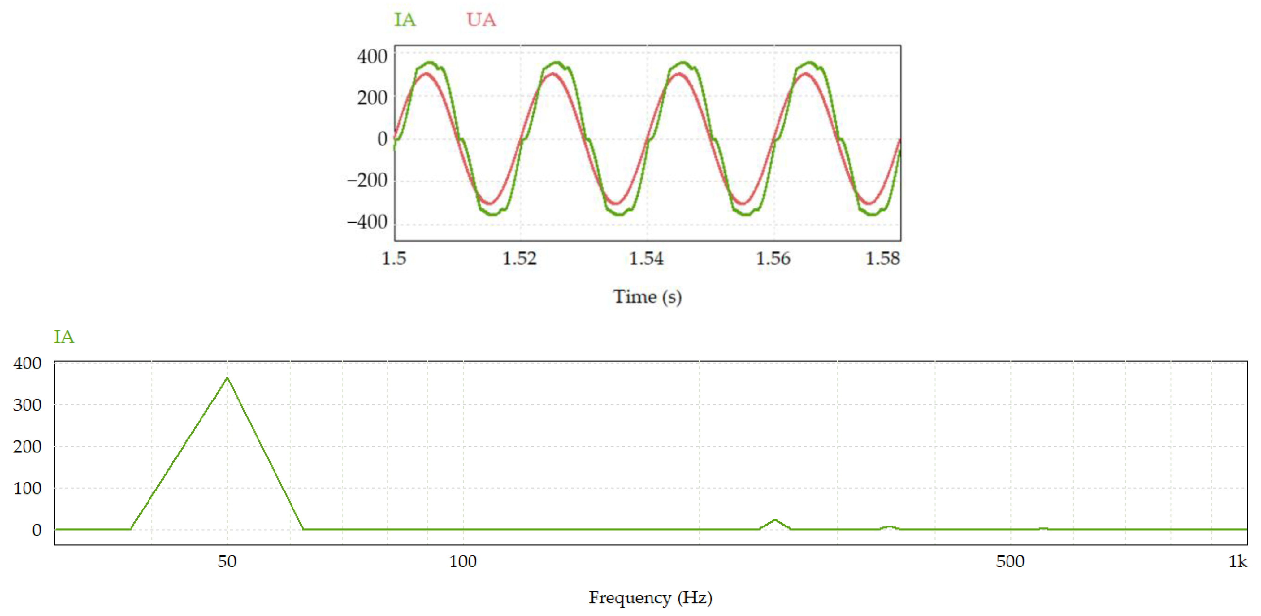
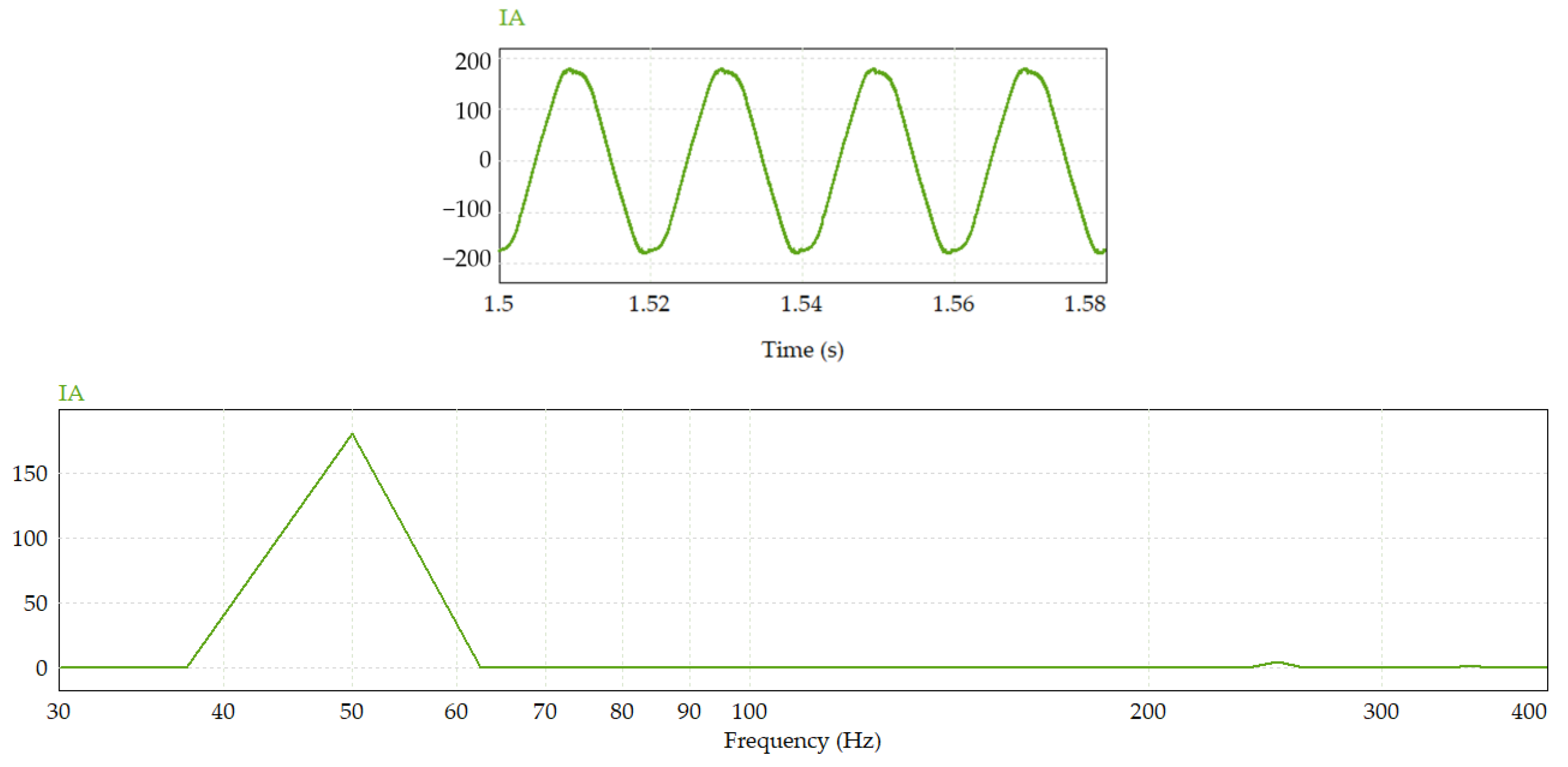
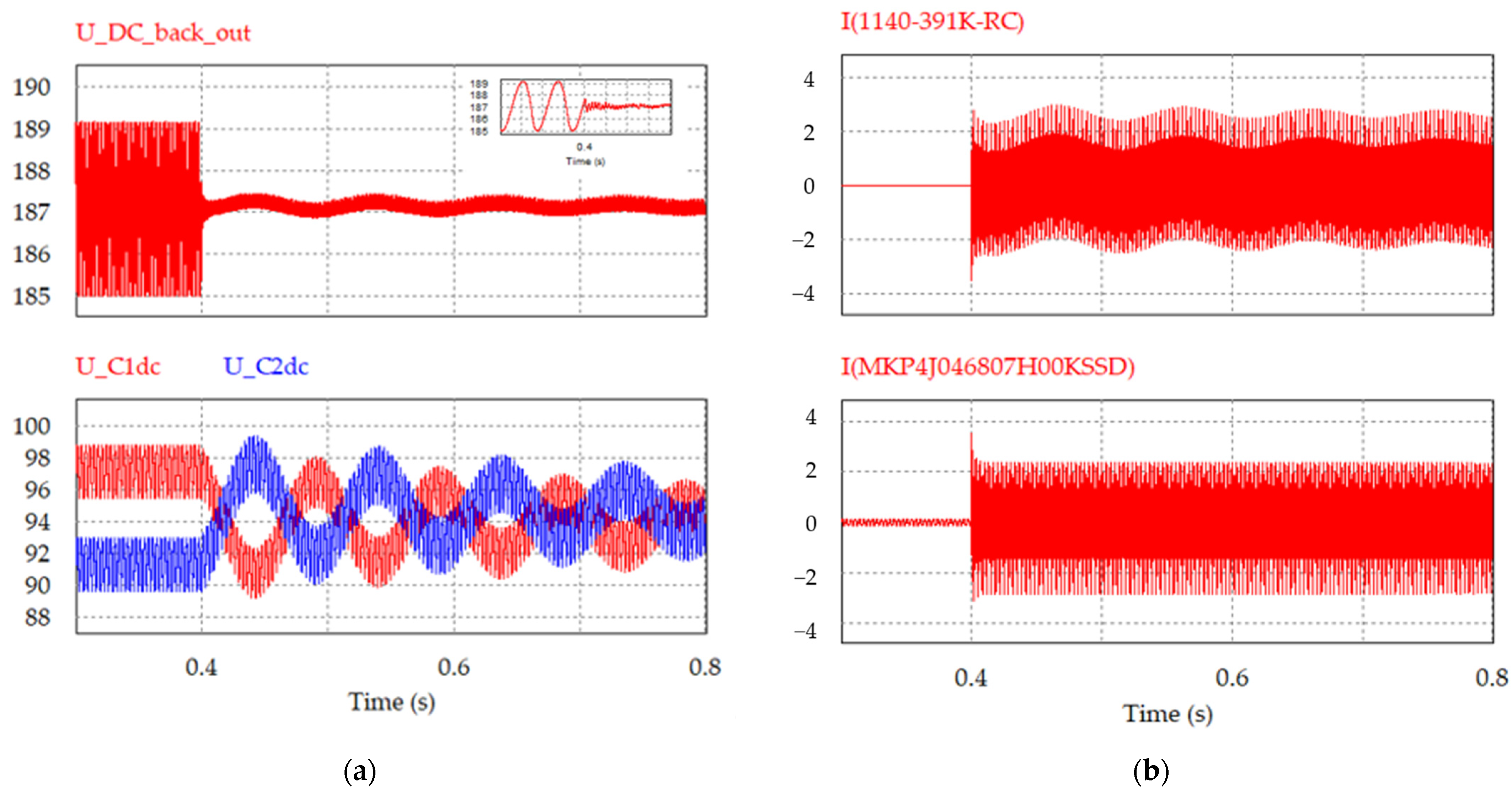
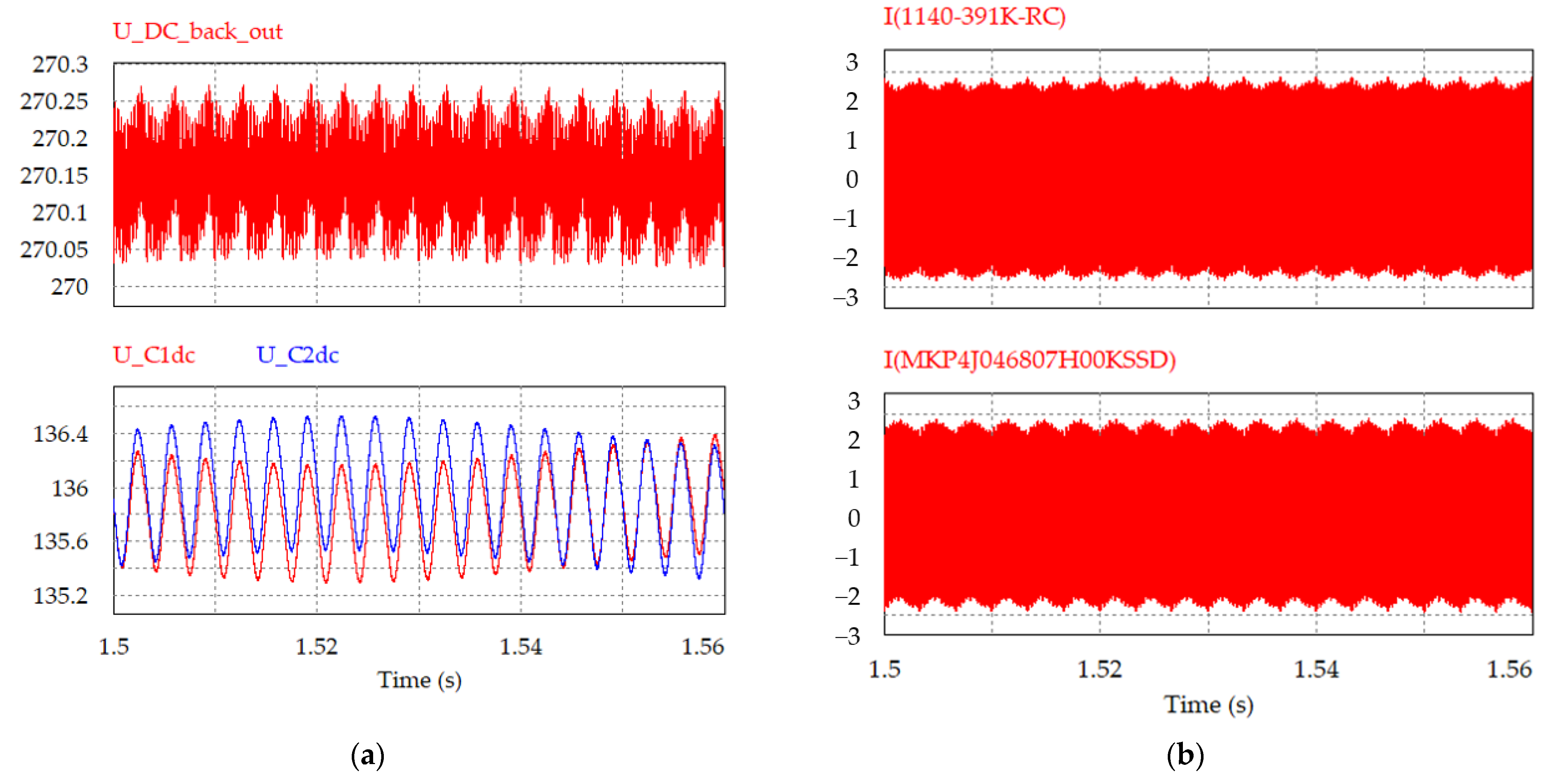
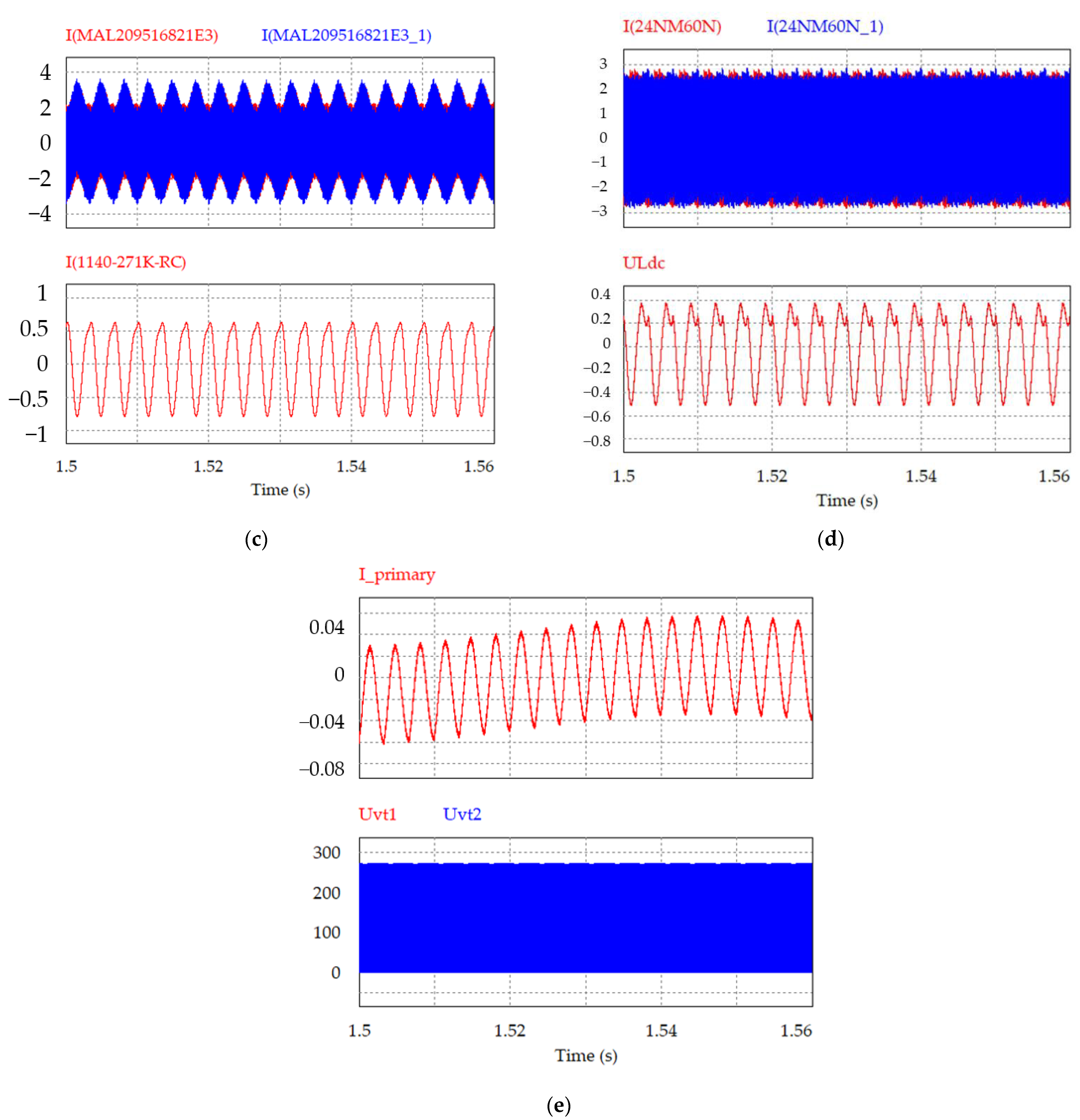
8. Experiment Results

An experiment was carried out with an active filter based on a half-bridge circuit of a single-phase voltage inverter. The experimental model was practically a digital twin of the device. All elements of the scheme corresponded to real objects. Carrying this out on a physical model was impossible due to the long manufacturing time of the transformer and the lack of an NRT 160.220 charging and rectifying device in the laboratory; it is an enterprise-scale device. A photo of the NRT 160.220 is shown in Figure 31.
However, several tests were carried out with the element parameters shown in Table 1:
  • Uin = 253 V, Uout = 187 V, M = 4.89, Rl = 1.113 Om, switching of the filter, with a choke in the DC link, reset surge of the main voltage 253–126.5–253 V;
  • Uin = 253 V, Uout = 187 V, M = 4.89, Rl = 1.113 Om, switching of the filter, two capacitors in parallel in the DC link, reset surge of the main voltage 253–126.5–253 V;
  • Uin = 253 V, Uout = 187 V, M = 4.89, Rl = 1.113 Om, switching of the filter, without a choke in the DC link, reset surge of the main voltage 253–126.5–253 V;
  • Uin = 253 V, Uout = 187 V, M = 4.89, Rl = 1.113 Om, switching of the filter, two capacitors in parallel and without a choke in the DC link, reset surge of the main voltage 126.5–253–126.5 V;
  • Uin = 253 V, Uout = 187 V, M = 4.89, Rl = 1.113 Om, the active filter does not work, the transistors are closed;
  • Uin = 253 V, Uout = 187 V, M = 4.89, Rl = 1.113 Om, the transition process;
  • Uin = 187 V, Uout = 270 V, M = 9.76, Rl = 1.715 Om, the maximum voltage of the charging and rectifying device;
  • Operate on counter-EMF;
  • Uin = 253 V, Uout = 187 V, M = 4.89, Rl = 1.113 Om, without filter capacitor at the output of the charging and rectifying device, ripple 3.188 V, THDI = 0.233%.
Figure 32 shows the oscillograms of the active filter at different points of the circuit at the time of switching of the active filter, obtained in the PSIM software (Professional 2022.2.0.17). At the output voltage maximum of the charging and rectifying device, the ripple level with the active filter turned on remains minimal (Figure 33). The results were obtained in dynamics and at a high frequency (33 kHz); in this regard, the signal period is not visible, and only the moment when the active filter is turned on is visible. Also, the output voltage value of the charging and rectifying device is interesting here. Figure 33 shows the transition process itself, where you can see the value of the output voltage ripple, and the simulation data of specific figures are given in Table 4. For convenience, some figures show a scale scan.
Table 4 shows the simulation results, as well as the level of the ripple coefficient (Kp).
The presence of an active filter in the charging and rectifying device allowed for reducing voltage ripples up to 6 times, which also allowed for reducing the number of filter capacitors at the output of the rectifier of the charging and rectifying device from 6 units, 6800 μF each, to 3 units [78].

9. Conclusions

Improving the quality of electrical energy is one of the priorities along with the distribution of electricity throughout the state. An increasing number of nonlinear, active inductive loads and their different phase distributions can lead to a deterioration in the quality of network operation. This may include the presence of high-frequency harmonic components that can reach electricity consumers and the presence of reactive power, which leads to inefficient use of electricity. Many people often overpay for electricity due to a poor power factor, less than 0.9, and also because of the uneven distribution over the phases of the network. In the case of accidents, an asymmetry may appear in a three-phase network, which can negatively affect the operation of both industrial and household appliances. In this regard, variants of devices that improve electrical energy quality have been proposed. AC voltage regulators were introduced, mainly with a switched quasi-impedance of the power supply, but the main emphasis was placed on an active filter based on a half-bridge inverter.
When analyzing the active filter, special attention was paid to the battery charge, namely the quality of current and voltage with a minimum level of pulsations in the DC link. At the same time, a charger with an active filter must remain mobile, which implies a reduction in its weight and dimensions. Thus, it was proposed to abandon bulky chokes and switch to an active filter based on a half-bridge inverter. Compared to similar solutions [43,55], the proposed active filter uses a control system with a control loop for the output current of the active filter. This made it possible to limit current surges on the primary side of the transformer. The pulsation coefficient was less than 1%, while for analogs, this value reached 2.5%. Thus, the following conclusions were made:
  • The required ripple level did not exceed 0.2%.
  • The possibility of compensation of the pulsation component is achieved both at a small output voltage value of the rectifier of the charging and rectifying device and at a maximum equal to 270 V, where the pulsation was 0.2 V.
  • The presence of only two transistors indicates a low level of energy loss on semiconductors—25 W, which will reduce the size of the radiator.
  • The disadvantages include a non-standard type of matching transformer; this will affect the cost of the entire power supply system.
Obtaining such a low level of ripple indicates that the goal was achieved, the implementation of the pulsating voltage form filtering, where the ripple value was more than 4 V, and after filtering less than 0.6 V, which was 0.1–0.2%.
Electrical energy quality “conditioners” based on AC voltage regulators were also presented. The considered converters can be used as reactive power regulators, active harmonic filters, compensators of voltage drop and symmetrical devices in multiphase networks.

Author Contributions

Conceptualization, A.U.; methodology, A.U. and E.K.; software, E.K.; validation, E.G. and A.M.; formal analysis, A.U.; investigation, A.U. and E.K.; resources, A.U. and E.K.; data curation, A.U.; writing—original draft preparation, A.U.; writing—review and editing, A.U., A.M. and E.K.; visualization, A.U.; supervision, E.G. and A.M.; project administration, A.U.; funding acquisition, A.U., E.G. and E.K. All authors have read and agreed to the published version of the manuscript.

Funding

The work was carried out with the support of the Russian Science Foundation No. 23-29-10055, https://rscf.ru/project/23-29-10055/ (accessed on 11 November 2023), with the support of the Government of Novosibirsk Region, agreement No. r-67.

Data Availability Statement

The data presented in this study are available on request from the corresponding author. The data are not publicly available due to privacy issues.

Conflicts of Interest

The authors declare no conflict of interest.

References

  1. Global Voltage Stabilizer System Industry (2020 to 2027)—Market Trends and Drivers. Available online: https://finance.yahoo.com/news/global-voltage-stabilizer-system-industry-093300514.html (accessed on 27 October 2023).
  2. Tokarev, V.G.; Brovanov, S.V. An Investigation of the Performance of Single-and Double-Converter Parallel Active Power Filters under Various Modulation Modes. In Proceedings of the 2021 XV International Scientific-Technical Conference on Actual Problems Of Electronic Instrument Engineering (APEIE), Novosibirsk, Russia, 19–21 November 2021; pp. 111–114. [Google Scholar] [CrossRef]
  3. Banerji, A.; Biswas, S.K.; Singh, B. Review of Static Compensation of Autonomous Systems. Int. J. Power Electron. Drive Syst. 2012, 2, 51. [Google Scholar] [CrossRef]
  4. Ruman, S.; Hameed, S. A Novel Approach for Design and Analysis of Voltage-Controlled DSTATCOM for Power Quality Enhancement. TELKOMNIKA Indones. J. Electr. Eng. 2015, 15, 486–496. [Google Scholar] [CrossRef]
  5. Akagi, H.; Watanabe, E.H.; Aredes, M. Instantaneous Power Theory and Applications to Power Conditioning; John Wiley & Sons: Hoboken, NJ, USA, 2017. [Google Scholar]
  6. Agrawal, A.; Agarwal, P.; Jena, P. Compensation of voltage flicker using unified power quality conditioner (UPQC). In Proceedings of the 2014 IEEE International Conference on Power Electronics, Drives and Energy Systems (PEDES), Mumbai, India, 16–19 December 2014; pp. 1–5. [Google Scholar] [CrossRef]
  7. Bezborodov, S.P.; Zinoviev, G.S. Analysis of the operating mode of the “inverted” voltage inverter. In Conversion Technology; NETI: Novosibirsk, Russia, 1975. (In Russian) [Google Scholar]
  8. Zinoviev, G.S. Analysis of voltage inverters as a reactive power compensator. In Conversion Technology; NETI: Novosibirsk, Russia, 1978. (In Russian) [Google Scholar]
  9. Zinoviev, G.S. Valve compensators of reactive power, distortion power and asymmetry power based on a voltage inverter. In Modern Tasks of Transformative Technology; Naukova dumka: Kiev, Ukraine, 1975; pp. 247–252. (In Russian) [Google Scholar]
  10. Muneshima, M.; Nishida, Y. A multilevel AC-AC conversion system and control method using Y-connected H-bridge circuits and bidirectional switches. In Proceedings of the 2013 IEEE Energy Conversion Congress and Exposition, Denver, CO, USA, 15–19 September 2013; pp. 4008–4013. [Google Scholar] [CrossRef]
  11. Alaei, R.; Khajehoddin, S.A.; Xu, W. A bidirectional ac/ac multilevel converter. In Proceedings of the 2015 IEEE Energy Conversion Congress and Exposition (ECCE), Montreal, QC, Canada, 20–24 September 2015; pp. 2610–2615. [Google Scholar] [CrossRef]
  12. Keyhani, H.; Toliyat, H.A. A soft-switched three-phase AC–AC converter with a high-frequency AC link. IEEE Trans. Ind. Appl. 2013, 50, 2637–2647. [Google Scholar] [CrossRef]
  13. Petry, C.A.; Fagundes, J.C.; Barbi, I. New direct ac-ac converters using switching modules solving the commutation problem. In Proceedings of the 2006 IEEE International Symposium on Industrial Electronics, Montreal, QC, Canada, 9–13 July 2006; Volume 2, pp. 864–869. [Google Scholar] [CrossRef]
  14. Khan, M.M.; Rana, A.; Dong, F. Improved ac/ac choppers-based voltage regulator designs. IET Power Electron. 2014, 7, 1989–2000. [Google Scholar] [CrossRef]
  15. Petry, C.A.; Fagundes, J.C.S.; Barbi, I. New AC-AC converter topologies. In Proceedings of the 2003 IEEE International Symposium on Industrial Electronics (Cat. No. 03TH8692), Rio de Janeiro, Brazil, 9–11 June 2003; Volume 1, pp. 427–431. [Google Scholar] [CrossRef]
  16. Ahmed, N.A.; Miyatake, M.; Lee, H.W.; Nakaoka, M. A novel circuit topology of three-phase direct AC-AC PWM voltage regulator. In Proceedings of the Conference Record of the 2006 IEEE Industry Applications Conference Forty-First IAS Annual Meeting, Tampa, FL, USA, 8–12 October 2006; Volmue 4, pp. 2076–2081. [Google Scholar] [CrossRef]
  17. Fedyczak, Z.; Szcześniak, P.; Kaniewski, J.; Korbicz, J. Direct PWM AC choppers and frequency converters. In Measurements Models Systems and Design; Transport and Communication Publishers: Warsaw, Poland, 2007; pp. 393–424. [Google Scholar]
  18. Kartashev, I.I.; Chekhov, V.I. Static Reactive Power Compensators in Power Systems; Ryzhov, Y.P., Ed.; Publishing House of the MEI: Moscow, Russia, 1990; 68p. (In Russian) [Google Scholar]
  19. Tikhomirov, A.A.; Cherepanov, D.A.; Tikhonov, E.A.; Sysun, V.I. Transverse reactive power compensation scheme based on the electromechanical effect. Int. Res. J. 2014, 11 Pt 2, 71–72. (In Russian) [Google Scholar]
  20. Tarabin, I.V.; Skokov, R.B.; Terekhin, I.A.; Gorbachev, S.A. Reactive power compensation as a method of improving the quality of electrical energy and reducing losses on the example of IDGC of SIBERIA data. Fundam. Res. 2015, 2, 4876–4879. (In Russian) [Google Scholar]
  21. Magonov, S.V.; Shibeko, R.V. Reactive power compensation. In Youth and Science: Actual Problems of Fundamental and Applied Research; Federal State Budgetary Educational Institution of Higher Education Komsomolsk-on-Amur State University: Komsomolsk-on-Amur, Russia, 2019; pp. 346–349. (In Russian) [Google Scholar]
  22. Braslavsky, I.Y. Induction Semiconductor Electric Drive with Parametric Control; Energoatomizdat: Moscow, Russia, 1988. (In Russian) [Google Scholar]
  23. Strzelecki, R.M. (Ed.) Power Electronics in Smart Electrical Energy Networks; Springer Science & Business Media: Berlin/Heidelberg, Germany, 2008. [Google Scholar] [CrossRef]
  24. Zinoviev, G. Power Electronics; Novosibirsk State Technical University: Novosibirsk, Russia, 2014. (In Russian) [Google Scholar]
  25. Hofmeester, N.H.M.; Van den Bosch, P.P.J.; Klaassens, J.B. Modelling and control of an AC/AC boost-buck converter. In Proceedings of the 1993 Fifth European Conference on Power Electronics and Applications, Brighton, UK, 13–16 September 1993; pp. 85–90. [Google Scholar]
  26. Srinivasan, S.; Venkataramanan, G. Comparative evaluation of PWM AC-AC converters. In Proceedings of the PESC’95-Power Electronics Specialist Conference, Atlanta, GA, USA, 18–22 June 1995; Volume 1, pp. 529–535. [Google Scholar] [CrossRef]
  27. Zinoviev, G.S. Valve Converter. Russian Federation RF 2124263, 27 December 1998. (In Russian). [Google Scholar]
  28. Zinoviev, G.S.; Obukhov, A.E. Increasing pulse-width regulators of alternating voltage. Sci. Bull. Novosib. State Tech. Univ. 1997, 3, 111–120. (In Russian) [Google Scholar]
  29. Obuhov, A.; Otchenash, V.; Zinoviev, G. Buck-boost AC-AC voltage controllers. In Proceedings of the 9th International Conference on Power Electronics and Motion Control (EPE-PEMC 2000), Košice, Slovakia, 5–7 September 2000; pp. 194–197. [Google Scholar]
  30. Montero-Hernadez, O.C.; Enjeti, P.N. Application of a boost AC-AC converter to compensate for voltage sags in electric power distribution systems. In Proceedings of the 2000 IEEE 31st Annual Power Electronics Specialists Conference, Conference Proceedings (Cat. No. 00CH37018), Galway, Ireland, 23 June 2000; Volume 1, pp. 470–475. [Google Scholar] [CrossRef]
  31. Fedyczak, Z.; Klytta, M.; Strzelecki, R. Three-phase AC-AC semiconductor transformer topologies and applications. In Proceedings of the PEDC 2001: 2nd Conference, Zielona Góra, Polska, 3–5 September 2001; pp. 25–38. [Google Scholar]
  32. Peng, F.Z.; Chen, L.; Zhang, F. Simple topologies of PWM AC-AC converters. IEEE Power Electron. Lett. 2003, 1, 10–13. [Google Scholar] [CrossRef]
  33. Floricău, D.; Dumitrescu, M.; Popa, I.; Ivanov, S. Basic Topologies of Direct PWM AC Choppers; Annals of the University of Craiova, Electrical Engineering Series; Craiova University: Craiova, Romania, 2006; Volume 30. [Google Scholar]
  34. Prasai, A.; Divan, D. Dynamic capacitor—VAR and harmonic compensation without inverters. In Proceedings of the 2011 14th European Conference on Power Electronics and Applications, Birmingham, UK, 30 August–1 September 2011; pp. 1–10. [Google Scholar]
  35. Liu, Q.; Deng, Y.; He, X. A novel AC-AC shunt active power filter without large energy storage elements. In Proceedings of the 2011 14th European Conference on Power Electronics and Applications, Birmingham, UK, 30 August–1 September 2011; pp. 1–9. [Google Scholar]
  36. Brescia, E.; Massenio, P.R.; Di Nardo, M.; Cascella, G.L.; Gerada, C.; Cupertino, F. Nonintrusive Parameter Identification of IoT-Embedded Isotropic PMSM Drives. IEEE J. Emerg. Sel. Top. Power Electron. 2023, 11, 5195–5207. [Google Scholar] [CrossRef]
  37. Brescia, E.; Massenio, P.R.; Di Nardo, M.; Cascella, G.L.; Gerada, C.; Cupertino, F. Parameter Estimation of Isotropic PMSMs Based on Multiple Steady-State Measurements Collected During Regular Operations. IEEE Trans. Energy Convers. 2023, 1–16. [Google Scholar] [CrossRef]
  38. Dudin, A.; Ellinger, T.; Petzoldt, J.; Nos, O.V. State of charge control of the mixed-type battery energy storage system based on the modular multilevel converter. In Proceedings of the 2016 17th International Conference of Young Specialists on Micro/Nanotechnologies and Electron Devices (EDM), Altai, Russia, 30 June–4 July 2016; pp. 395–400. [Google Scholar] [CrossRef]
  39. Reithmaier, S. DC-DC High Frequency Boost Converter. U.S. Patent 7 180 275, B2, 20 February 2007. [Google Scholar]
  40. Brown, A.E. DC-DC Converter Operable in an Asyncronous or Syncronous or Linear Mode. U.S. Patent 5 414 341, 9 May 1995. [Google Scholar]
  41. BU-907: Testing Lithium-Based Batteries. Available online: https://batteryuniversity.com/index.php/learn/article/testing_lithium_based_batteries (accessed on 27 October 2023).
  42. SKiiP 603 GD123-3DUL V3. Available online: https://www.semikron-danfoss.com/products/product-classes/ipm.html#view/table/items/20/filters/icnom-in-a=600 (accessed on 27 October 2023).
  43. Agunov, A.V. Smoothing device of DC traction substations based on a power active filter. News St. Petersburg Univ. Railw. Transp. 2013, 2, 96–99. (In Russian) [Google Scholar]
  44. Zhang, H.; Lu, R.; Zhu, C.; Zhao, Y. On-line measurement of internal resistance of lithium ion battery for EV and its application research. Int. J. u-e-Serv. Sci. Technol. 2014, 7, 301–310. [Google Scholar] [CrossRef]
  45. Hato, Y.; Chen, C.H.; Hirota, T.; Kamiya, Y.; Daisho, Y.; Inami, S. Degradation predictions of lithium iron phosphate battery. World Electr. Veh. J. 2015, 7, 25–31. [Google Scholar] [CrossRef]
  46. Ruddell, A.J.; Dutton, A.G.; Wenzl, H.; Ropeter, C.; Sauer, D.U.; Merten, J.; Orfanogiannis, C.; Twidell, J.W.; Vezin, P. Analysis of battery current microcycles in autonomous renewable energy systems. J. Power Source 2002, 112, 531–546. [Google Scholar] [CrossRef]
  47. Charging LiFeP04 Batteries Summary of Manufacturer Recommendations. Available online: http://www.hoffmanengineering.com/Power-Management-from-Hoffman-Engineering (accessed on 27 October 2023).
  48. Park, J.H.; Jeong, H.G.; Lee, K.B. Output current ripple reduction algorithms for home energy storage systems. Energies 2013, 6, 5552–5569. [Google Scholar] [CrossRef]
  49. Kaneko, G.; Inoue, S.; Taniguchi, K.; Hirota, T.; Kamiya, Y.; Daisho, Y.; Inami, S. Analysis of degradation mechanism of lithium iron phosphate battery. World Electr. Veh. J. 2013, 6, 555–561. [Google Scholar] [CrossRef]
  50. From 1 Hour to Just 10 Seconds: Using the Low-Frequency AC-IR Method as a Quicker and More Stable Alternative to DC-IR Testing of Lithium Ion Batteries. Available online: https://www.hioki.com/en/ (accessed on 27 October 2023).
  51. Keil, P.; Jossen, A. Charging protocols for lithium-ion batteries and their impact on cycle life—An experimental study with different 18650 high-power cells. J. Energy Storage 2016, 6, 125–141. [Google Scholar] [CrossRef]
  52. Krieger, E.M. Effects of Variability and Rate on Battery Charge Storage and Lifespan. Ph.D. Thesis, Princeton University, Princeton, NJ, USA, 2013. [Google Scholar]
  53. Ahmad, A.A.; Abrishamifar, A.; Samadi, S. Low-frequency current ripple reduction in front-end boost converter with single-phase inverter load. IET Power Electron. 2012, 5, 1676–1683. [Google Scholar] [CrossRef]
  54. Sritharan, T. Impact of Current Waveforms on Battery Behaviour; University of Toronto: Toronto, ON, Canada, 2012. [Google Scholar]
  55. Mirzaee, H.; Dutta, S.; Bhattacharya, S. A medium-voltage DC (MVDC) with series active injection for shipboard power system applications. In Proceedings of the 2010 IEEE Energy Conversion Congress and Exposition, Atlanta, GA, USA, 12–16 September 2010; pp. 2865–2870. [Google Scholar] [CrossRef]
  56. Hayes, T.C.; Horowitz, P. The art of Electronics; Cambridge University Press: Cambridge, UK, 1999; Volume 3. [Google Scholar]
  57. Ahmed, H.F.; Cha, H.; Khan, A.A. Design of dynamic voltage restorer for voltage sag and swell compensation using high-frequency-isolated direct AC-AC converter without commutation problem. In Proceedings of the 2015 17th European Conference on Power Electronics and Applications (EPE’15 ECCE-Europe), Geneva, Switzerland, 8–10 September 2015; pp. 1–10. [Google Scholar] [CrossRef]
  58. Wen, B.; Zhang, X.; Wang, Q.; Burgos, R.; Mattavelli, P.; Boroyevich, D. Comparison of three-phase ac-ac matrix converter and voltage dc-link back-to-back converter topologies based on EMI filter. In Proceedings of the 2013 IEEE Energy Conversion Congress and Exposition, Denver, CO, USA, 15–19 September 2013; pp. 2698–2706. [Google Scholar] [CrossRef]
  59. Qin, H.; Kimball, J.W. Ac-ac dual active bridge converter for solid state transformer. In Proceedings of the 2009 IEEE Energy Conversion Congress and Exposition, San Jose, CA, USA, 20–24 September 2009; pp. 3039–3044. [Google Scholar] [CrossRef]
  60. Keyhani, H.; Toliyat, H.A. Isolated ZVS high-frequency-link AC-AC converter with a reduced switch count. IEEE Trans. Power Electron. 2013, 29, 4156–4166. [Google Scholar] [CrossRef]
  61. Yu, X.; She, X.; Ni, X.; Huang, A.Q. System integration and hierarchical power management strategy for a solid-state transformer interfaced microgrid system. IEEE Trans. Power Electron. 2013, 29, 4414–4425. [Google Scholar] [CrossRef]
  62. Besselmann, T.; Mester, A.; Dujic, D. Power electronic traction transformer: Efficiency improvements under light-load conditions. IEEE Trans. Power Electron. 2013, 29, 3971–3981. [Google Scholar] [CrossRef]
  63. Zinoviev, G.S.; Konovalov, A.I.; Krasikov, N.A. Adjustable Converter of Alternating Voltage to Alternating. Certificate of Authorship No. 1128350; Bul. No. 45, 1984. (In Russian). [Google Scholar]
  64. Zinoviev, G.S.; Ulanov, E.I. Voltage Inverter Control Method. Certificate of Authorship No. 576651; Bul. No. 38, 1979. (In Russian). [Google Scholar]
  65. Zinoviev, G.S.; Manusov, V.Z. Direct Methods for Calculating the Energy Parameters of Valve Converters; Publishing House of Novosibirsk University: Novosibirsk, Russia, 1990. (In Russian) [Google Scholar]
  66. Zinoviev, G.S. Structures of valve converters with an arbitrary voltage conversion coefficient. Sci. Bull. NSTU 1997, 3, 71. (In Russian) [Google Scholar]
  67. Zinoviev, G.S.; Levin, E.Y.; Obukhov, A.E.; Popov, V.I. Step-up and step-down regulators of alternating voltage and direct frequency converters. Electr. Eng. 2000, 11, 16–20. (In Russian) [Google Scholar]
  68. Zinoviev, G.S.; Popov, A.V. Direct Frequency Converter. RF Patent No. 2215359, 27 October 2003. Bul. No. 30. (In Russian). [Google Scholar]
  69. Zinoviev, G.S.; Zotov, L.G. An Up-and-Down Direct Frequency Converter. RF Patent No. 2408968, 10 January 2011. Byul. 13. (In Russian). [Google Scholar]
  70. Zinoviev, G.S.; Sidorov, A.V.; Kharitonov, S.A. Three-Phase AC Voltage Stabilizer. RF Patent 2529887, 10 October 2014. Bul. No. 28. (In Russian). [Google Scholar]
  71. Zotov, L.G.; Zinoviev, G.S. Electronic transformers based on high-frequency resonant structures with switchable capacitors. Rep. Tomsk. State Univ. Control Syst. Radioelectron. 2013, 2, 64–69. (In Russian) [Google Scholar]
  72. Zinoviev, G.S.; Udovichenko, A.V. AC Voltage Regulator. Patent 2479102, 10 April 2013. Bul. No. 10. (In Russian). [Google Scholar]
  73. Zinoviev, G.S.; Udovichenko, A.V. Transformerless buck-boost AC voltage regulators with sinusoidal input and output currents. Tech. Elektrodynamika 2012, 3, 69–70. (In Russian) [Google Scholar]
  74. Zinoviev, G.S.; Udovichenko, A.V. Transformerless buck-boost AC voltage regulators with sinusoidal currents for soft–start devices of induction motors. In Proceedings of the Electric Drives of Alternating Current—EPT-2012, Ekaterinburg, Russia, 12–16 March 2012; pp. 55–58. (In Russian). [Google Scholar]
  75. Tekin, H.; Bulut, K.; Ertekin, D. A novel switched-capacitor and fuzzy logic-based quadratic boost converter with mitigated voltage stress, applicable for DC micro-grid. Electr. Eng. 2022, 104, 4391–4413. [Google Scholar] [CrossRef]
  76. Qi, Q.; Ghaderi, D.; Guerrero, J.M. Sliding mode controller-based switched-capacitor-based high DC gain and low voltage stress DC-DC boost converter for photovoltaic applications. Int. J. Electr. Power Energy Syst. 2021, 125, 106496. [Google Scholar] [CrossRef]
  77. Zabolev, R.Y. Dynamic Modes in Controlled Valve Converters; NSTU: Novosibirsk, Russia, 1997; 32p. (In Russian) [Google Scholar]
  78. Kosykh, E.; Udovichenko, A.; Lopatkin, N.; Zinoviev, G.; Grishanov, E.; Sarakhanova, R. Analysis of the Control System for a Soft Starter of an Induction Motor Based on a Multi-Zone AC Voltage Converter. Electronics 2022, 12, 56. [Google Scholar] [CrossRef]
  79. Construction of a Digital Filter with a Finite Impulse Response. Available online: http://habrahabr.ru/post/128140/ (accessed on 27 October 2023). (In Russian).
Figure 1. Circuit of a charging and rectifying device with an active filter.
Symmetry 15 02092 g001
Figure 2. The scheme of the pulsation component selection (VS—voltage sensor, ZOH—zero-order sampling/hold, K—proportional coefficient).
Symmetry 15 02092 g002
Figure 3. Protection scheme of the active filter (ZOH—zero-order sampling/hold).
Symmetry 15 02092 g003
Figure 4. The power unit of the active filter.
Symmetry 15 02092 g004
Figure 5. Phase shift correction (red is the input signal, blue is the signal after the high-pass filter, black is the output signal).
Symmetry 15 02092 g005
Figure 6. A simple circuit of a buck–boost AC voltage regulator with a switched quasi-impedance of the power supply.
Symmetry 15 02092 g006
Figure 7. AC voltage regulator with switched quasi-impedance of the power supply.
Symmetry 15 02092 g007
Figure 8. AC voltage regulator with a switched quasi-impedance of the power supply and a capacitor in the load.
Symmetry 15 02092 g008
Figure 9. AC voltage regulator with a switched quasi-impedance of the power supply and a capacitor in the load after the AC switch.
Symmetry 15 02092 g009
Figure 10. A simple circuit of a buck–boost AC voltage regulator with a switched quasi-impedance of the power supply.
Symmetry 15 02092 g010
Figure 11. Control characteristics.
Symmetry 15 02092 g011
Figure 12. Load characteristics.
Symmetry 15 02092 g012
Figure 13. The dependence of the input power factor, THD, on the modulation depth.
Symmetry 15 02092 g013
Figure 14. AC voltage regulator as an active filter.
Symmetry 15 02092 g014
Figure 15. Active filter control system (CS—current sensor).
Symmetry 15 02092 g015
Figure 16. Input current and voltage, harmonic spectrum of the input current, before compensation (red—voltage, green—current).
Symmetry 15 02092 g016
Figure 17. Input current, the harmonic spectrum of the input current after switching on the AC voltage regulator in the system.
Symmetry 15 02092 g017
Figure 18. Two-zone AC voltage regulator as a reactive power compensator.
Symmetry 15 02092 g018
Figure 19. Reactive power compensator control system (CS—current sensor).
Symmetry 15 02092 g019
Figure 20. Input current and voltage, output current and voltage (top—input, bottom—output, red—voltage, green—current).
Symmetry 15 02092 g020
Figure 21. Input current and voltage, output current and voltage after compensation (top—input, bottom—output, red—voltage, green/blue—current).
Symmetry 15 02092 g021
Figure 22. Drop compensator control system (VS—voltage sensor).
Symmetry 15 02092 g022
Figure 23. An AC voltage regulator, as a compensator for asymmetry.
Symmetry 15 02092 g023
Figure 24. Control system of the asymmetry compensator (VS—voltage sensor).
Symmetry 15 02092 g024
Figure 25. Input current (top) and output voltage (bottom) with an unbalanced load.
Symmetry 15 02092 g025
Figure 26. Input current (top) and output voltage (bottom) with an unbalanced load after compensation.
Symmetry 15 02092 g026
Figure 27. A flicker effect compensator based on an AC voltage regulator.
Symmetry 15 02092 g027
Figure 28. Control system of the flicker compensator (CS—current sensor).
Symmetry 15 02092 g028
Figure 29. Input voltage, harmonic composition (before compensation).
Symmetry 15 02092 g029
Figure 30. The result after switching of AC voltage regulator in the system (after compensation).
Symmetry 15 02092 g030
Figure 31. Photo of the charging and rectifying device NRT 160.220.
Symmetry 15 02092 g031
Figure 32. Oscillograms of Uin = 253 V, Uout = 187 V, M = 4.89, Rl = 1.113 Om, transient ((a) voltage of the charging and rectifying device before and after the active filter (top), the DC-link capacitor voltage of the active filter (bottom); (b) the choke current of the active filter output (top), the capacitor current of the active filter output (bottom); (c) the capacitor current of the active filter DC link (top), the choke current of the active filter DC link (bottom); (d) active filter transistor current (top), DC-link choke voltage (bottom); (e) the primary-side current of the active filter (top), the transistor voltage of the active filter (bottom)).
Symmetry 15 02092 g032aSymmetry 15 02092 g032b
Figure 33. Oscillograms of Uin = 187 V, Uout = 270 V, M = 9.76, Rl = 1.715 Om, maximum voltage of the charging and rectifying device ((a) voltage of the charging and rectifying device after the active filter (top), the DC-link capacitor voltage of the active filter (bottom); (b) the choke current of the active filter output (top), the capacitor current of the active filter output (bottom); (c) the capacitor current of the active filter DC link (top), the choke current of the active filter DC link (bottom); (d) active filter transistor current (top), DC-link choke voltage (bottom); (e) the primary-side current of the active filter (top), the transistor voltage of the active filter (bottom)).
Symmetry 15 02092 g033aSymmetry 15 02092 g033b
Table 1. Parameters of the transformer, LC elements and transistors.
Requirements for an Active Filter
Transformer T2
Output voltage range, V72.1–135
Ripple amplitude range, V3.2–5.9
The current of the secondary winding of the matching transformer, A168
Pulsation frequency, Hz300
Power, W188.5
Transformer efficiency, %98
Inverter
Transistors S1, S224NM60N
Transistor current, A3.696
The maximum voltage applied to the transistor, V270
Inductance of the choke on the AC side, Lf1, μH390
Capacitance of the capacitor on the AC side, Cf4, μF6.8
Inductance of the choke on the DC side, Ldc, μH270
Capacitance of the capacitor on the DC side, CDC, μF820
Table 2. Comparison of AC-AC converters.
Type of ConverterNumber of Transistors per PhaseNumber of Reactive Elements per PhaseThe Possibility of Increasing the Voltage
AC voltage regulator with switchable cells and reactors68Yes
A converter operating as a unidirectional buck regulator of alternating voltage, as well as a bidirectional boost regulator85Yes
Matrix converter63No
H-bridge scheme162No
AC-AC resonant converter with high-frequency link43Yes
AC-AC regulator with soft switching167No
Three-phase AC-AC regulator with soft switching46No
Matrix converter with a reactive voltage source104Yes
Matrix converter with modification of the control method63Yes
Matrix converter with a combination of pulse-width modulation and pulse-width regulation in the control system63Yes
A circuit with a combined matrix converter and a boost AC voltage regulator44Yes
A circuit with a combined bridge matrix converter and an AC voltage Ćuk regulator76Yes
Combination of an AC voltage Ćuk regulator according to a classical zero matrix converter32Yes
An AC voltage regulator based on the concept of introducing a volt-additive using a high-frequency conversion31Yes
An AC voltage regulator based on the Arkadiev–Marx concept84Yes
A simple circuit of a buck–boost AC voltage regulator with a switched quasi-impedance of the power supply14Yes
AC voltage regulator with a switched quasi-impedance of the power supply12Yes
AC voltage regulator with a switched quasi-impedance of the power supply and a capacitor in the load13Yes
Table 3. Comparison of the proposed topologies in terms of their effectiveness.
Type of ConverterModulation DepthTHDI(ADE), %THDI(PSIM), %Efficiency, %
AC voltage regulator with a switched quasi-impedance of the power supply and a capacitor in the load0.753.23.198
A simple circuit of a buck–boost AC voltage regulator with a switched quasi-impedance of the power supply0.743.9496
Table 4. Simulation results and ripple coefficient level.
Uin, V253253220220220187
Uout, V187232220220232270
Udcmax, V187.348232.299220.424218.941232.313270.269
Udcmin, V187.003231.964220.11218.614231.971270.029
Udcave, V187.174232.129220.265218.777232.144270.148
KpU, %0.184320.1443160.1425560.1494670.1473220.08884
KpU/KpU(without an active filter)6.6005936.2862365.3711825.2151444.82612.662608
KpU(without an active filter)—the ripple coefficient of the output voltage of the charging and rectifying device in the absence of an active filter.
Disclaimer/Publisher’s Note: The statements, opinions and data contained in all publications are solely those of the individual author(s) and contributor(s) and not of MDPI and/or the editor(s). MDPI and/or the editor(s) disclaim responsibility for any injury to people or property resulting from any ideas, methods, instructions or products referred to in the content.

