Article

A Quantum-Based Signcryption for Supervisory Control and Data Acquisition (SCADA) Networks

1
Faculty of Computer Science, Dalhousie University, Halifax, NS B3H 4R2, Canada
2
Research and Development, Cistel Technology, Ottawa, ON K2E 7V7, Canada
3
Sanstream Technology, Gatineau, QC J8Y 2V5, Canada
*
Author to whom correspondence should be addressed.
Symmetry 2022, 14(8), 1625; https://doi.org/10.3390/sym14081625
Submission received: 14 June 2022 / Revised: 22 July 2022 / Accepted: 4 August 2022 / Published: 7 August 2022
(This article belongs to the Special Issue Symmetry and Asymmetry in Quantum Cryptography)

Abstract

:
Supervisory Control and Data Acquisition (SCADA) systems are ubiquitous in industrial control processes, such as power grids, water supply systems, traffic control, oil and natural gas mining, space stations and nuclear plants. However, their security faces the threat of being compromised due to the increasing use of open-access networks. Furthermore, one of the research gaps involves the emergence of quantum computing, which has exposed a new type of risk to SCADA systems. Failure to secure SCADA systems can lead to catastrophic consequences. For example, a malicious attack can take control of the power supply to a city, shut down the water supply system, or cause malfunction of a nuclear reactor. The primary purpose of this paper is to identify the new type of attack based on quantum computing and design a novel security scheme to defend against traditional attacks as well as the quantum attack. The methodology of the proposed signcryption is built on the foundation of the classical Bennett and Brassard 1984 (BB84) cryptographic scheme and does not involve computationally expensive third-party validation. The proposed signcryption scheme provides both encryption and intrusion detection. In particular, it detects the man-in-the-middle attack that can lead to other types of attacks. We have simulated the proposed algorithm using the Quantum Information Toolkit in Python. Furthermore, we have validated and analyzed the proposed design through security verification tools, namely, Scyther and PRISM.

1. Introduction

Supervisory Control and Data Acquisition (SCADA) systems monitor infrastructure or industrial processes such as in electric grids, water treatment plants, nuclear plants, and oil and natural gas pipelines. The SCADA architecture follows a hierarchical structure with three levels: (1) the supervisory level includes the Master Terminal Unit (MTU) and Human–Machine Interface (HMI); (2) The process control level involves sub-Master Terminal Unit (sub-MTU); (3) The field instrumentation control level contains field devices called Remote Terminal Units (RTUs) [1,2,3,4].
Due to their open access nature [5], SCADA systems suffer from various cyber-attacks and need appropriate detection and prevention techniques. For example, in December 2015, a cyber-attack using spear-phishing emails on power plants in Ukraine left 230,000 people without power for hours. Researchers and organizations throughout the world have proposed various security standards and protocols to improve SCADA network security. However, these traditional schemes do not exploit all the domains of security requirements and are therefore ineffective against many attacks [4].
The dawn of the quantum computer is not only valuable but also a risk to cyber-security. According to Shor’s algorithm [6] and Grover’s algorithm [7], a quantum computer can crack classical encryption schemes, including Elliptic Curve Cryptography (ECC) [8]. The existing standards and communication protocols are inadequate for satisfactory protection against specific traditional attacks and quantum attacks.
There are two types of cryptography, namely, asymmetric and symmetric. The current SCADA standard, AGA-12, uses the popular RSA asymmetric algorithm. The security of RSA relies on the difficulty of factorizing large prime numbers. However, unlike classical algorithms, a quantum algorithm can easily crack the factorization problem by using the superposition principle. A classical algorithm consumes O(N); however, an extensive search based on Grover’s algorithm in a quantum setting takes O( N ) [9]. Thus, symmetric algorithms such as AES are weakened by Grover’s quantum search algorithm. Moreover, Akinori et al. [10] have recently theoretically studied the quantum collision attack on the SHA-256 and SHA-512 algorithm. The advancement of quantum computing brings the requirement of stronger cyber-security to SCADA systems. We conclude that organizations and industries based on critical infrastructures should implement an amalgamation of quantum and classical algorithms to thwart both types of attacks.
Concerns about security of SCADA networks are not new [4]:
  • Existing standards do not provide strong confidentiality, integrity and availability.
  • Existing intrusion detection systems do not provide confidentiality.
  • Existing key management protocols fail to provide confidentiality and availability.
  • Current security schemes do not provide resistance against an attack launched by a quantum computer.
To the best of our knowledge, we did not come across any prior research work that provides a robust and secure system for existing SCADA systems using a quantum-secure encryption scheme and key exchange algorithm.
  • We have identified one possible attack based on quantum computing on SCADA systems.
  • We propose a new security scheme, to prevent unauthorized access to SCADA systems, and protect against the traditional as well as the quantum attack. Furthermore, the proposed scheme provides both encryption and intrusion detection. The scheme generates a signcrypted message by using the Bennett and Brassard 1984 (BB84) protocol and a one-time digital signature. Unlike other signcryption schemes, this scheme does not depend on a third party.
The difference between our approach and the existing works is that we use quantum key distribution instead of a traditional key exchange algorithm. Furthermore, we use the quantum key to generate the signcrypted data. The microchip circuits developed at QETLabs can generate and distribute keys encoded in qubits by utilizing the quantum properties of superposition and entanglement. This chip presents an opportunity to apply Quantum Key Distribution (QKD) to resource-constrained devices [11]. This rapid development and adoption of chip-based QKD is the motivation of the proposed signcryption scheme.

Outline of the Paper

Section 2 provides an in-depth literature survey on existing error correction protocols used in Quantum Key Distribution and One-time Digital Signature schemes used to develop our proposed scheme. In Section 3, we identify the possible quantum attack on SCADA networks and list the attacks (both traditional and quantum) that can be defended by our proposed scheme. We also provide a brief survey on current SCADA security protocols. Section 4 describes the proposed scheme for SCADA networks. Section 5 provides the formal analysis of the scheme. Section 6 gives the evaluation results of the implemented proposed scheme. Section 7 provides conclusion and future work, respectively.

2. Background

This section provides a background survey on existing procedures used in quantum key exchange protocols as well as the ones that have contributed to developing the proposed scheme. Cryptography provides secure data exchange by providing the three main goals of security, namely, confidentiality, integrity, and authentication [12]. Based on the number of communication channels, it can be categorized into classical and quantum cryptography. Classical cryptography is based on the mathematical computation that uses a single communication channel. It can be further categorized into asymmetric and symmetric cryptography, depending upon the number and the characteristics of the keys used for encryption [12]. On the other hand, quantum cryptography relies on the principles of quantum mechanics, and it uses two channels, namely, a quantum channel and a public channel [13]. A quantum channel exchanges qubits, which are the fundamental units of information in quantum computing. A public channel or a classical channel is one where data are exchanged in the form of bits between the sender and the receiver.
Table 1 provides a description of some of the terminology used in quantum cryptography. To obtain more in-depth background on this subject, we refer the reader to the articles [12,13,14,15,16,17,18,19,20].
A quantum channel can create noise in the presence of an intruder or due to environmental factors, thus disrupting the key exchange. Quantum cryptography uses error correction protocols to resolve these errors. After the raw quantum key exchange, the system follows a process called key sifting. In a SCADA system that uses quantum cryptography, both the MTU and RTU randomly choose the basis, i.e., a vector, to generate and measure the superposed state of qubits. The sender and receiver negotiate their choice of basis via the less secure public channel. After the negotiation, they estimate the errors present in their respective keys [13].
This section presents the background work on existing error correction algorithms used in quantum key exchange protocols and the algorithms that have contributed to developing the proposed scheme. It has the following sub-sections:
  • Existing Error Correction Protocols Used in Quantum Key Exchange System;
  • Error Correction Protocol proposed for wireless network;
  • Error Correction Protocol used in the Proposed Security Scheme;
  • One-time Digital Signature.

2.1. Existing Error Correction Protocols Used in Quantum Key Exchange Systems

In this section, we discuss the following protocols that have been proposed and used to reconcile the errors while preserving security in the exchanged key [17].

2.1.1. Cascade

The Cascade protocol is one of the most prominent error reconciliation protocols developed by Bennett and Brassard [17]. In this scheme, the sender and the receiver calculate the error estimation and agree on block size and seed. They segment their keys into agreed-sized blocks and exchange the two-bit parity of each of their blocks. When there is a parity mismatch, they perform a binary search of the corresponding block to find a single-bit error. After the search, the error is detected and resolved, which is the first complete pass of the protocol. In each succeeding pass, they double the block size and repeat the same process [17]. It is a simple protocol which is computationally efficient and involves frequent interaction between the sender and receiver.

2.1.2. Winnow

Butler et al. [17,21] propose a protocol named Winnow, which significantly reduces the interaction between the sender and receiver. Instead of using binary search, it uses Hamming code to identify and correct single-bit errors. Furthermore, this protocol introduces errors in the key during the process in case of non-uniform error distribution [17,21].
The Winnow segments the primary key into blocks. Before segmentation, the sender and receiver perform error estimation. Based on the error rate, they agree on the block size in increasing powers of 2, for example, 8, 16, 32, 64, and 128. They exchange and compare the parity of each block. In case the parity does not match, they compare the syndrome deduced by using the Hamming hash function. The number of passes depends on the error rate [17,21].
Hamming Code Structure: A Hamming code follows even parity bits. It detects two-bit errors and resolves single-bit errors. In a Hamming codeword, parity bits are bits with positions of power of 2. The remaining bits are data. For example, when a message with four binary digits uses the Hamming function, it adds three parity bits by giving a (7,4) codeword, as shown in Figure 1.
Hamming Code Algorithm [17,21,22]: To determine the value of parity bits, the sequence of bits is alternatively checked and skipped. For example, suppose a sender sends data of binary digits 1101 to the receiver. For P1, we check and skip 1 bit, and the checked positions are (1, 3, 5, 7, 9). For P2, we check and skip 2 bits, which gives (2, 3; 6, 7; 10, 11) checked positions. For P4, we check and skip 4 bits, which returns the following bit positions: (4, 5, 6, 7; 12, 13, 14, 15).
For P1, the parity for D3, D5, D7 or 101 is 0 because it follows even parity. Since the number of 1s is even, the parity is 0; else, it will be 1. Therefore, P1 is 0. For P2, the parity for D3, D6, D7 or 111 is 1, and thus, P2 is 1. Similarly, the P4 for D5, D6, D7 or 011 is 0. Therefore, the obtained Hamming codeword is 1100110 for the message 1101. At the receiver’s side, the bits on positions (1, 3, 5, 7), (2, 3, 6, 7) and (4, 5, 6, 7) are checked using even parity. If P1, P2 and P4 is 0, then no error is present in the received codeword. If the error is present in any of the parities, the parity value is 1. For example, if P1 and P4 are 1, then the received codeword is wrong. The error word is P4, P2, and P1, which yields 101. The decimal value of 101 is obtained and depicts that the fifth bit of the codeword is incorrect, and thus, it is flipped.
As per the property of Hamming code, it can detect and correct one error per block. If that block contains a large number of errors, it introduces a new error to the block. We can use a smaller block size to avoid this situation. However, it results in a large number of blocks with a consequent increase in the number of parity bits and the amount of information leaked [17].

2.1.3. Low-Density Parity Check (LDPC)

The LDPC uses a parity check matrix H and a generator matrix G. The dimensions of both the matrices is m × n such that n × k = m × j where m is the number of rows and n is the number of columns. The j is the number of 1s in each row, and the k is the number of 1s in each column. G denotes the Generator matrix, and H denotes the parity matrix. The values of j and k are small compared to the number of rows and code length. Therefore, H has a low density of 1s. The H is called a low-density parity check matrix. Moreover, the code defined by H is called a low-density parity check code [17].
In quantum transmission, the error correction code does not use the Generator matrix, and the Parity matrix is perceived as a Tanner graph [17]. In the H matrix, each row is the check node with each column being the variable node. The check node signifies the parity check based on syndrome calculation. The variable node represents the single bits of the message [17].
In a single information exchange, the LDPC resolves all the errors in the transmitted key. Unlike Cascade and Winnow, it does not follow any parity or key segmentation. The sender calculates the syndrome for the key and sends it to the receiver. The receiver calculates the syndrome based on his obtained key. It then uses the sender’s syndrome to detect and resolve the errors in the key. The receiver uses a decoding algorithm to detect the error locations in the key. The most common algorithm used in LDPC is the Sum-Product algorithm [17].
In Winnow, the message segments use the Hamming Code and can only correct single-bit errors. In LDPC, the syndrome is larger. Therefore, it can correct multiple errors with less communication overhead as compared to Winnow and Cascade. However, the computational complexity is significantly higher than that of the other two protocols.

2.2. Error Correction Protocol Proposed for Wireless Networks: Low Complexity Parity Check (LCPC)

SCADA involves RTUs and field devices that are resource constrained. Thus, we conducted a literature review on the error correction schemes for wireless networks. This section focuses on the Low Complexity Parity Check (LCPC) protocol [23], as described as follows.

Low Complexity Parity Check (LCPC) Protocol

Alabady et al. [17,23] proposed a low complexity parity check code for wireless network applications. It has less complexity and requires less memory as compared to that of LDPC. The LDPC performs better in case of a larger codeword and a low density parity matrix. However, it consumes more memory and requires complex decoding and computation [17,23].
The LCPC segments the binary message into equal bits. Each segmented source datum follows the error-correcting algorithm. Thus, it yields a codeword which is sent via the public channel. The receiver checks for errors in the received codeword. If any error is present, it resolves them using syndrome. Finally, it decodes the codeword [23].
The LCPC has the following methods to encode and decode the codeword [23].
Step 1, Segmentation: The source data are segmented into equal blocks. We discuss LCPC (9,4) as an example. It uses 56-bit source data which follows segmentation into 4-bit length blocks. The source code now contains fourteen 4-bit blocks.
Step 2, LCPC encoding: Each 4-bit block x i uses LCPC (9,4). In this step, the algorithm generates a codeword using a parity-check matrix and Generator matrix. For example, source data (SD) = x i is 1010.
For x i = 1010, each bit is represented as β 1 = 1, β 2 = 0, β 3 = 1, and β 4 = 0. The LCPC follows even parity. The parities are obtained using the following equations [23].
P 5 = β 1 β 2 β 3 β 4 P 6 = β 1 β 2 β 3 P 7 = β 1 β 2 β 4 P 8 = β 1 β 3 β 4 P 9 = β 2 β 3 β 4 ,
where ⊕ is the XOR operator symbol.
Thus, the deduced parity bits are P5 = 0, P6 = 0, P7 = 1, P8 = 0 and P9 = 1. When parity bits are added to the x i , it gives the codeword CD = 101000101. This codeword is sent to the receiver. Furthermore, the Generator matrix G and the Parity check matrix H obtained are as follows.
H = [ 1 1 1 1 1 0 0 0 0 1 1 1 0 0 1 0 0 0 1 1 0 1 0 0 1 0 0 1 0 1 1 0 0 0 1 0 0 1 1 1 0 0 0 0 1 ]
G = [ 1 0 0 0 1 1 1 1 0 0 1 0 0 1 1 1 0 1 0 0 1 0 1 1 0 1 1 0 0 0 1 1 0 1 1 1 ]
Step 3, LCPC Decoding: The receiver obtains the codeword with or without error. It performs three sub-steps. Sub-step1: It detects any error present in the codeword. Sub-step2: If an error is detected, it checks and determines the error pattern. Sub-step3: Finally, it corrects the error and decodes the codeword. Let the codeword c be transmitted, and vector r is the received codeword such that it satisfies the following equation.
r = c + e
where e is the error vector.
The technique uses the syndrome vector for error detection and correction. A syndrome vector indicates whether the equation is satisfied for that particular codeword. If the value of syndrome s is zero, it denotes that no error has occurred, and the received codeword r is the correct one (c). Otherwise, it detects that the codeword is with an error.
If H is the parity-check matrix of c, then,
H r T = H ( c + e ) T = H c T + H r T
H c T = 0
H r T = H e T = s
HrT is the syndrome of r.
When the syndrome has a non-zero value, the column of the H matrix which is a scalar multiple of the s is searched. If no such column is found, the code contains more than one error and it fails to correct multiple errors. Otherwise, if the syndrome is α times that particular column j, then the vector is added with α on the jth bit-position and with 0 on the rest bit-positions.
After the error correction, the receiver decodes the codeword using a masking process on its last left four bits. It involves using the AND operator between the corrected codeword and 111100000.
Although LCPC is more efficient in respect to computational cost and memory requirement as compared to other protocols, it fails to correct burst errors. In quantum transmission, there are significant chances of burst errors in the quantum key. Cascade and Winnow protocols can correct single-bit errors, and LDPC can correct multiple bit errors.

2.3. Error Correction Protocol Used in the Proposed Security Scheme

This section provides a brief overview of Reed–Solomon (R-S) protocol which is further explained in Section 4.1.3. In our proposed security scheme, we have used the R-S protocol for error correction to protect against partial or tampered data [24]. Due to the high computational and complexity cost, LDPC requires and exhausts more hardware resource which hampers the system applications. Reed–Solomon is a multi-bit error-correcting protocol with a low computational overhead as compared to LDPC [24].

2.4. Post-Quantum Digital Signature: One-Time Digital Signature

This section focuses on the one-time digital signature (OTS) scheme. It is based on a hash function that signs one message per key pair. A generic OTS is a set of three algorithms, namely, (1) Generating one-time key pairs that include public and private keys, (2) Obtaining a one-time signature, and (3) Verifying the obtained signature [20]. One of the well-known OTS schemes is the Lamport–Diffie scheme where the key used for signing (sk) is randomly generated, and the verification key (vk) is generated by applying a hash function on the sk [25,26,27]. This feature of Lamport Signature scheme has been used in the proposed scheme to generate a signcrypted message.

3. Related Work and Possible Attacks on SCADA Networks

In Section 2, we discussed the background work that is required to understand the fundamentals of the proposed scheme. In this section, we will discuss the current standards and protocols proposed and widely used in SCADA systems. We also discuss the possible attacks that can be launched based on quantum computing on SCADA networks.
SCADA is one of the critical infrastructures that collects real-time data and controls industrial processes. In recent years, several successful attacks have been launched on SCADA networks that have been a wake-up call for implementing updated security protocols. One of the major attacks on SCADA systems was the Stuxnet worm [28] that propagated using USB drives or network connections. It presented to the infected host as one of the SCADA systems and performed a man-in-the-middle attack. Thus, it led to a violation of data integrity and confidentiality. The main goals of a man-in-the-middle attack on SCADA systems are to disable the SCADA systems, exchange false or improper control commands, sabotage the PLC commands, and gain sensitive information in industrial processes [28].
The US Department of Homeland Security’s (DHS) Industrial Control Systems Cyber Emergency Team (ICS-CERT) has released various guidelines to mitigate the malware such as Stuxnet. One of the guidelines involved the requirement of an algorithm with adequate entropy to generate sufficiently random keys [29]. Our proposed algorithm used Quantum Key Distribution that generates truly random keys. Furthermore, various researchers have proposed multiple mitigation strategies involving host-based and network-based intrusion detection systems. For example, Carcano et al. [30] proposed an IDS that monitors the network traffic based on state anomalies. Furthermore, Ponomarev et al. [31] proposed hardware fingerprinting to detect SSH host spoofing, and the National Institute of Standards and Technology has proposed attack mitigation techniques based on firewalls to defend against man-in-the-middle attacks.
There have been significant research work and organizational efforts to protect SCADA network from cyber-attacks [4]. We classified the existing security schemes into three: current standards used for SCADA networks, detection of SCADA attacks and prevention of SCADA attacks. All of the existing protocols and security schemes use traditional cryptography. Even the current standards, including IEC 62351 and AGA-12, are based on traditional algorithms. It makes them vulnerable to attacks from a quantum computer. Furthermore, existing public key algorithms tend to increase computational and time cost [4].

3.1. Possible Attacks on SCADA Networks

In this paper, we identify the following primary attacks on SCADA networks: (1) traditional man-in-the-middle attack (2) brute-force with quantum computer. Table 2 summarizes the attacks on SCADA networks.

3.1.1. Man-in-the-Middle Attack

In our previous paper [4], we have discussed standard attacks on SCADA networks. An attacker can launch a man-in-the-middle attack between two victims to fetch the information passing over the communication channel between the RTU and the MTU by eavesdropping and capturing packets. By using tools such as Ettercap and Evilgrade [32], the man-in-the-middle attack can be extended to other attacks such as data injection [4].

3.1.2. Brute-Force Attack Using Quantum Computer

In recent years, the rapid development of quantum computers has posed a threat to cybersecurity. A quantum computer can solve and crack mathematical operations, for example, the problem of factoring enormous numbers, which is the core of any encryption scheme. AGA-12 uses RSA-1024 bit as the key management protocol and AES as the encryption scheme. In [4], we discussed that the two quantum algorithms, namely, Shor’s algorithm and Grover’s algorithm, can theoretically crack RSA and AES schemes, respectively. Since Grover’s algorithm provides a square root acceleration over the classical search algorithm, the AES-256 offers an adequate key strength of 64 bits [9]. Therefore, Grover’s algorithm has weakened AES but not broken it. However, recently, Gidney et al. [33] practically proved that the Shor’s algorithm cracks RSA-2048 within 8 h with 20 million qubits. Therefore, we believe that a quantum computer can successfully launch a brute force attack on AGA-12 standard to crack the RSA protocol.
Modern SCADA networks rely on Internet connectivity, cloud computing, and wireless communications. These have made its infrastructure susceptible to various attacks. Mostly, the man-in-the-middle (MiM) attack is the source of every other attack. Thus, the proposed quantum-resistant security scheme mainly focuses on the detection and prevention of the MiM attack and the brute force attack by Shor’s algorithm. It also provides security against the attacks discussed [4].

4. Proposed Security Scheme

In a generalized signature-then-encryption scheme, a digital signature scheme is initially applied, and a private key is used to encrypt the plain text and the digital signature together [19,34]. However, a generalized signcryption involves using a secret key that is obtained from the public key of the receiver. The secret key is used to encrypt the message and obtain the cipher. Simultaneously, it uses the private key of the sender to generate a digital signature. The cipher and the signature are sent to the receiver [19,34].
However, in our proposed scheme, we do not follow the above-mentioned signature-then-encryption scheme steps. Instead, we follow the generalized steps of a signcryption scheme. However, in place of the public key, we use a quantum key, which is secret as well as shared between the sender and receiver. The private key is obtained from the quantum key to generate the digital signature. Simultaneously, the quantum key encrypts the message to generate a cipher.
To the best of our knowledge, we believe that our proposed scheme is the first solution for SCADA networks against quantum computing.
The current security schemes in SCADA networks use key management and authentication protocol that are weak against quantum algorithms. In this paper, we propose a new scheme to guard the communication channel between RTU and MTU from quantum as well as traditional attacks. Moreover, Fröhlich et al. [35] demonstrated that BB84 protocol can provide successful key distribution over distances up to 240 km.
In our proposed scheme, we assume the following:
  • MTU has the identities and hashed IDs of all RTUs.
  • The ID of MTU is embedded in each and every RTU.
  • The RTU and MTU are aware of hash functions used to generate the private key.
  • The data stored in the legitimate units are secure.
  • The distance between the RTU and the MTU is maximum 200 km.
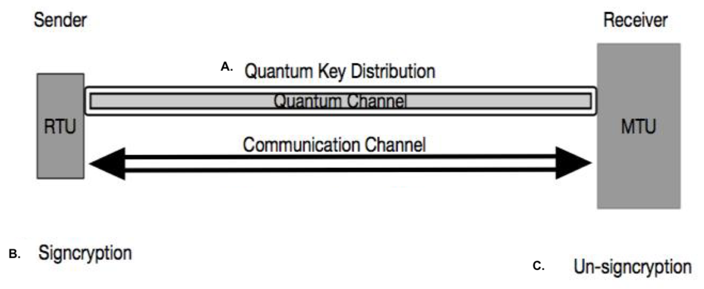
Sibson et al. [11] have developed a chip-based QKD in 2015. This evolution of Quantum Key Distribution (QKD) has motivated us to propose a quantum-based signcryption scheme for SCADA networks since they can be deployed in RTUs as well. However, both RTU and MTU need a few hardware changes. There is a need to amalgamate a monolithically integrated transmitter and a receiver with a photonic circuit using thermo-optic phase shifters in the RTU as well as in the MTU.
Quantum Cryptography exploits Heisenberg’s Uncertainty Principle [14] and the Principle of Photon Polarization [22]. According to Heisenberg’s Uncertainty Principle, it is not possible to obtain the position and momentum of a photon with absolute accuracy [14]. The Principle of Photon Polarization states that a photon can have a superposition of two or more quantum states at a time [15]. Furthermore, the No-Cloning Theorem [16] states that one can not produce an identical copy of an arbitrary quantum state of a photon. It makes quantum cryptography a feasible scheme to resist the threats of both a quantum and traditional computer. BB84 protocol is a popular Quantum Key Distribution (QKD) protocol and is the most suitable for IoT applications [36,37,38]. Our proposed scheme uses BB84 and has three main phases:
Phase A:
Quantum Key Distribution;
Phase B:
Signcryption;
Phase C:
Un-Signcryption.

4.1. Quantum Key Distribution: BB84 Protocol

This phase applies the BB84 protocol to generate a final quantum key [39] for signcryption. The Quantum Key Distribution protocol uses basis to generate and measure a qubit state.
A standard or canonical basis is denoted by state | 0 > , , | n 1 > which represents the following state [18].
| 0 > = [ 1 0 . . . 0 ] . . . . . | n 1 > = [ 0 0 . . . 1 ]
The normalized sum of all the standard basis is a diagonal basis vector. Since BB84 uses 45-degree and 135-degree polarization for a diagonal basis, the value of n is 2, the diagonal state | D > = | 0 > , | 1 > is represented in the following equation [18].
| D > = | 0 > + | 1 > 2
The bases are used to generate qubits with superposed states. It uses two bases: horizontal–vertical linear and diagonal directions. The key generation process uses the polarization of light. Each photon is polarized using one of the two bases randomly. The protocol employs two channels: a quantum channel for key generation and distribution, and classical channel for information transmission and eavesdrop detection. This phase has the following further steps:
  • Quantum Key Generation;
  • Key Sifting;
  • Error Correction;
  • Privacy Amplification.

4.1.1. Quantum Key Generation

The sender generates the first qubits by randomly using one of the bases and sends it to the receiver via the quantum channel. For example, RTU acts as the sender and MTU acts as the receiver, as shown in Figure 2. The series of first qubits is called raw bits [13,36].
The MTU reads each qubit with either of the two bases randomly and independently. The series of qubits received by the MTU is called the raw key. There are two cases of measuring the raw bits as following.
  • Case 1: The receiver has a 50% success rate of choosing the right basis to measure the bits and thus getting the correct bits.
  • Case 2: The receiver has a 50% failure rate where it selects the wrong basis. However, the outcome of using the wrong machine is random, which is either 0 or 1. Thus, the probability of incorrect bits in the received bits is 25%, and that of correct bits is 75%. This ratio persists in the absence of any eavesdropper [13,36].
When the qubits are measured using any basis, their state changes randomly. Furthermore, the states of the qubits cannot be cloned, which helps in the detection of an intruder. When an eavesdropper tries to read the qubits in the quantum channel, it disrupts the state of the qubits. Thus, the MTU receives the disrupted qubits. The MTU measures the tampered raw key, and the rate of incorrect qubits exceeds 25% [13,36].

4.1.2. Key Sifting

The MTU sends the randomly chosen basis to the RTU via the public channel. The RTU verifies its chosen basis with that of MTUs. Then, the RTU sends the incorrect basis to the MTU. Both the units discard the bits measured by the incorrect basis and obtain the sifted key. In case of no noise in the quantum channel, the sifted key of both the units is the same. In case of any presence of noise, there is an error in the sifted key deduced by MTU [13].

4.1.3. Error Correction Protocol

The error correction protocol in the quantum key distribution has the following sub-steps [13,36].
Step 1: Determine Quantum Bit Error Rate (QBER). A Quantum Bit Error Rate (QBER) is the fraction of mismatched qubits exchanged between the sender and the receiver [13]. The RTU calculates the QBER. The RTU and MTU randomly extract a part of its sifted key. The MTU discloses its extracted part to RTU. The RTU obtains the QBER by calculating the ratio of error and total number of bits in MTU’s extracted key. Both of the units discard the exposed part and obtain the sub-sifted key.
  • Case 1: If QBER is higher than 25%, both units discard the sifted key, and it generates the raw key again.
  • Case 2: If QBER is less than 25%, the units follow the error correction protocol and privacy amplification.
Step 2: Error Correction Protocol (ECP) used: Reed Solomon Code. In this phase, the sender and the receiver resolve the error in the sub-sifted key via the public channel. The error correction protocol phase is crucial after a quantum key exchange for the following reasons.
  • It helps both the units check the confidentiality and integrity of the obtained sub-sifted key.
  • The RTU sends its sub-sifted key encoding it with ECP protocol to MTU. The encoded key is called the codeword. The encoding involves adding extra bits or parity bits to the original data. It helps the receiver to detect and resolve the errors. Therefore, the eavesdropper is unable to read the original key. When the codeword is modified, it is detected as well as resolved by the MTU.
  • In this phase, based on the QBER, the sub-sifted key is corrected as the errors are reconciled.
As mentioned in Section 2, the most common error correction protocols are the Cascade protocol, Winnow protocol, Low-Density Parity Check (LDPC) protocol, Low Complexity Parity Check (LCPC) and the Reed–Solomon protocol (R-S) [17,23,24].
The most feasible protocol for wireless networks are the LCPC and Reed–Solomon protocols. The purpose of LCPC is to detect and correct single- and double-bit errors. However, during the quantum key exchange, the errors can occur in bursts. In that scenario, as mentioned in Section 2, the Reed–Solomon (R-S) code is a better suited protocol for implementing with the BB84 protocol. The R-S code is an efficient algebraic code which can correct a large number of errors with low overhead and low complexity. It has the power to correct errors in a cluster. Various storage systems, broadcast systems, and wireless networks widely adopts R-S code.
Characteristic of Reed–Solomon (R-S) code: It is a subgroup of Bose–Chaudhuri–Hocquenghem (BCH) codes [24] and linear codes which performs their arithmetic operations in a Galois field or finite field. BCH is a cyclic error-correcting code that involves using polynomials over data blocks. The code word generated in this algorithm consists of polynomials, which is divisible by another fixed short-length polynomial. The fixed polynomial is called a Generator polynomial [40].
A Reed–Solomon code is represented as R-S(nk) with s-bit symbols. It implies that the encoder takes k data symbols with s bits each. Then, it adds parity symbols, thus obtaining a code word of n symbols. The parity symbols of s bits each are n k . The R-S decoder can resolve up to t symbol errors in a codeword. It implies that it can automatically correct errors up to t bytes. The length of parity is calculated as follows [24,40]:
2 t = n k
The maximum codeword length (n) can be calculated as follows:
n = 2 s 1
R-S Encoder: In R-S encoding, the sub-sifted key is the message which is represented as a polynomial i(x). The polynomial is multiplied with the Generator polynomial g(x) [24,40].
c ( x ) = g ( x ) · i ( x )
where
  • c ( x ) is the valid codeword.
  • i ( x ) is the information block.
  • g ( x ) is the generator polynomial.
Using Lagrange interpolation, the polynomial is evaluated as:
p ( x ) = i ( x ) · x n k mod g ( x )
R-S Decoder: An error occurs when an incorrect bit is present in the codeword. An erasure occurs when the position of the incorrect bit is known [24,40]. The decoding algorithm uses the following outlined process to correct up to t errors or up to 2t erasures.
The received codeword can be represented as follows:
r ( x ) = c ( x ) + e ( x )
where r(x) is the received codeword, c(x) is the recovered codeword and e(x) is the error pattern present in the r(x).
The decoder follows the succeeding steps.
  • Syndrome calculator: It calculates the syndrome which is used to identify the symbol errors. One symbol error occurs when either 1 bit is incorrect or all the bits are incorrect in a symbol.
  • Error locator: It then finds the symbol error locations by calculating the error locator polynomial. It uses Euclid’s algorithm.
  • Calculate magnitude of error: Then, it finds the roots of the error locator polynomial.
  • Error evaluation: To calculate the symbol error values, the Forney algorithm is used.
Finally, a recovered codeword is received.

4.1.4. Privacy Amplification
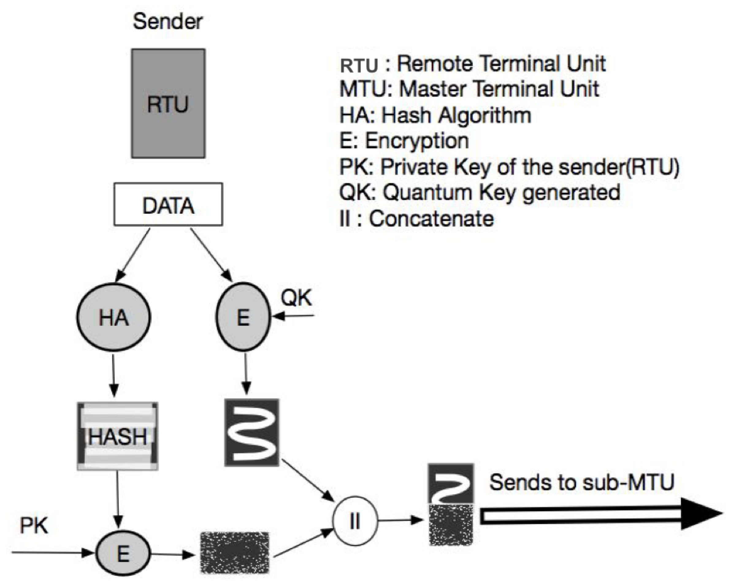
From the received and recovered codeword, the MTU extracts the sub-sifted key. To reduce any information leakage during error correction protocol and to increase the secrecy of the key, the MTU hashes the sub-sifted key. Both MTU and RTU obtain the finalized key or quantum key (QK).

4.2. Signcryption

Both the components have the finalized quantum key (QK). The RTU executes the following steps [41] as shown in Figure 3.
  • Encryption: The RTU makes a copy of the data and encrypts the data with the finalized quantum key.
  • One-Time Digital Signature: The RTU hashes the copy of the data. It then encrypts the hash with its private key (PK). It segments the quantum key into equal chunks. It then generates a private key by applying a hash function on one of the segments of the QK. It concatenates the hashed message, hashed unique ID of the RTU and a timestamp. The PK is used to encrypt the concatenated data, thus generating a one-time digital signature.
The RTU sends the signcrypted data to the MTU over the classical channel.

4.3. Un-Signcryption

The MTU receives the signcrypted data and executes the following steps. Furthermore, we assume that the MTU has the database which stores the information, including IDs of all the RTUs and their hash values. The MTU is also aware of the signcryption algorithm used by the RTU.
  • Decryption: The MTU decrypts the encrypted data with the quantum key (QK).
  • Validation: The MTU also decrypts the encrypted hashed value with the private key (PK). The MTU hashes the copied data by the same algorithm used by the RTU. Thus, the timestamp and the hashed ID is extracted and verified.

5. Formal Analysis of Proposed Model

The proposed scheme has two major parts, quantum and classical. We have performed the experiments on macOS with 1.8 GHz Intel Core i5 processor manufcatured by Apple Inc. and sourced from Halifax, Canada. The quantum part involves the BB84 protocol, and the classical part involves the Signcryption algorithm. Therefore, in this paper, we have used two tools for the formal analysis of the proposed scheme.
  • Modeling and Analysis of BB84 protocol in Prism.
  • Modeling and Analysis of Signcryption in Scyther.
Our proposed scheme is simulated in PRISM and Scyther for the specification, analysis, and verification of our security protocol. First, we verify the Quantum Key Distribution protocol on PRISM. We created the BB84 model that contains four modules: (i) Alice refers to RTU, (ii) Bob refers to MTU, (iii) Eve refers to the eavesdropper, and (iv) the quantum channel. In the simulation, we calculate the probability of detecting Eve and the extent of information leakage. After obtaining the quantum key, we model and analyze the signcryption in Scyther. We formalize the security requirements of our signcryption model based on the discrete logarithm problem (DLP) in Scyther. We claim specified security requirements, namely, secrecy of the key, data exchanged, and aliveness of the two parties symbolizing authentication. After the formal analysis of our proposed scheme, we implemented our algorithm on Python 3.6, involving three parties: RTU as the sender, MTU as the receiver, and Eve as the eavesdropper. We have also simulated the quantum channel, characterizing the noise of binary symmetric channel, on Python 3.6 with the help of a Quantum Information Toolkit (QIT).

5.1. Modeling and Analysis of Quantum Phase (BB84 Protocol) in Prism

The formal analysis of the security of Quantum Key Distribution has been completed by PRISM. However, ensuring provable practical security and breaching time analysis of the proposed scheme by considering the quantum adversary will require extensive quantum hardware or a quantum computer. This is planned for future work.
Prism is a probabilistic model checker to model and to analyze the systems based on probabilistic behavior. It automatically investigates the systems to find out flaws and errors in the system specification. The model checker feeds the following two types of inputs [42].
  • The description of the to-be-designed system. It mostly expresses the information in process algebras such that it acts as an input in model checker.
  • A set of rules or properties that the system must follow.
There are two stages to build a model in a Prism [42]:
Stage 1:
Model the system where it represents all the states and transitions of the system.
Stage 2:
Model the system where it expresses its properties in temporal logic statements.
When we execute the temporal logic statements against the model, it verifies whether and with what probability the properties hold for the system.
In this paper, the Discrete-Time Markov Chain (DTMC) model has been used to design the BB84 protocol system. While building the system, the following two properties of the system are defined:
  • Public channel handles the transmission of messages in such a way that the system monitors the process. However, the eavesdropper is unable to monitor the messages.
  • Quantum channel handles message exchange in such a way that any attempt by an eavesdropper to monitor the channel causes an alteration in the message and thus creates a noise.
Thus, the system detects any eavesdropping attack as well as cloning attack.
The following two types of attacks have been tested for this system [43].
  • Intercept–Resend Attack: The eavesdropper uses the basis once to measure the qubit. It measures a qubit, and the state of the qubit changes randomly.
  • Random–Substitute Attack: The eavesdropper uses the basis twice. At first, it uses the basis to measure the qubit. After fetching the value of the qubit, it reads the same qubit again to replace its value. It is an attempt to clone the state of the qubit.
In this paper, we analyze the following three factors of the BB84 protocol:
  • Whether the protocol detects any intrusion;
  • How much information is leaked processing the protocol;
  • Can BB84 protocol discard or prevent the eavesdropping attack.
The following six variables have been calculated and used in the models [43]:
  • P1 = Probability of detecting an eavesdropper (EVE);
  • P2 = Probability that EVE measures more than half of the information correctly;
  • N = No. of bits transferred;
  • Correct bits measured by Eve ≥ N/2;
  • L = LUCKY = Probability of obtaining correct value with wrong basis;
  • REPLACE = 0.5 = Probability of substituting with 0 or 1.
In this model, the probability value ranges from 0 to 1. Based on the type of attacks, there are two following major threat models.
  • Model 1: BB84 with intercept–resend eavesdropping attack;
  • Model 2: BB84 with random-substitute eavesdropping attack.
Table 3 and Table 4 show the probability of detecting the intruder launching eavesdropping attack or MiM attack. It also shows the probability of high information leakage.
Table 5 and Table 6 display the detection rate of the intruder attempting to clone the data or qubits. Simultaneously, it provides the probability of maximum information leakage.

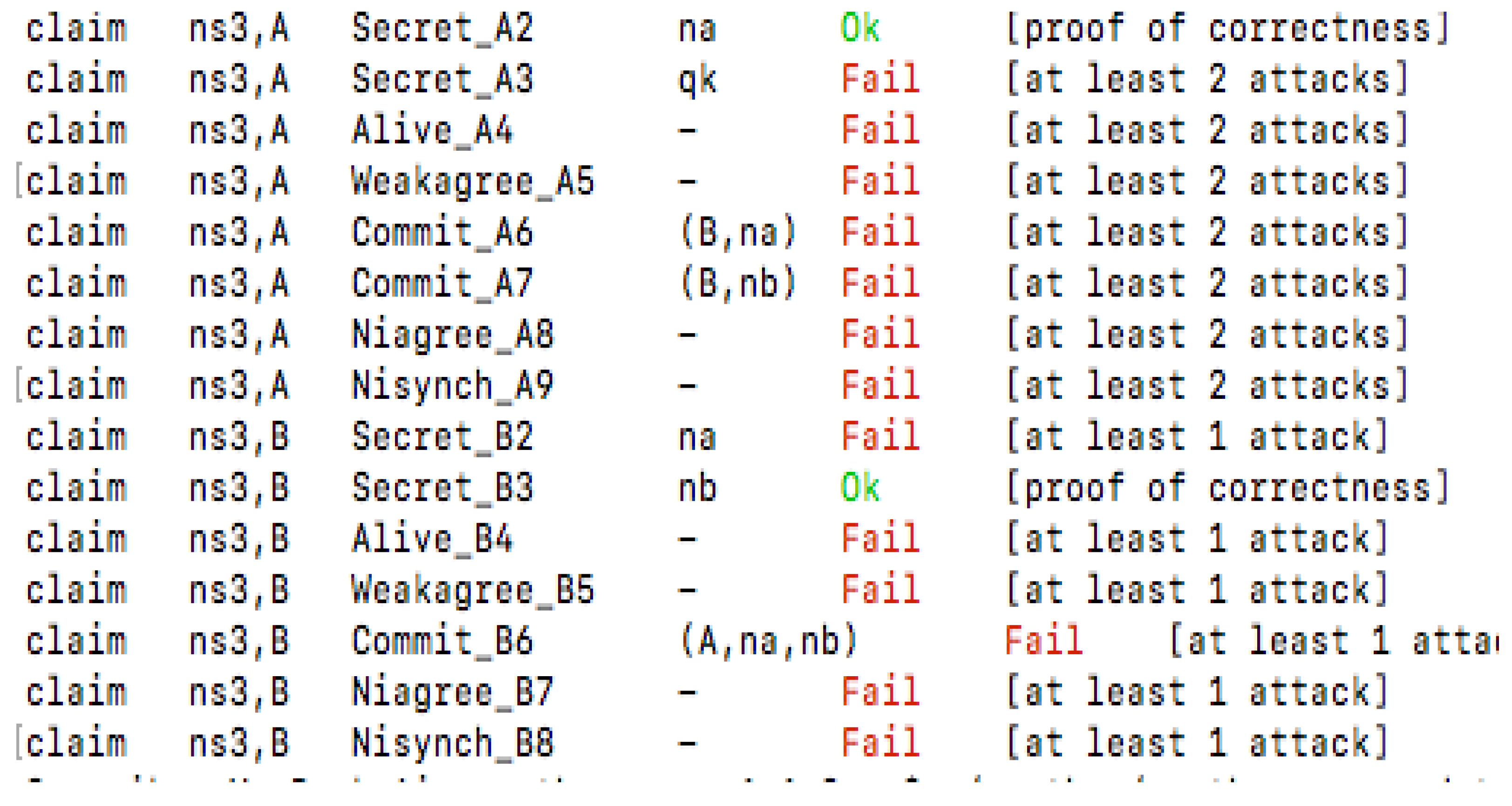
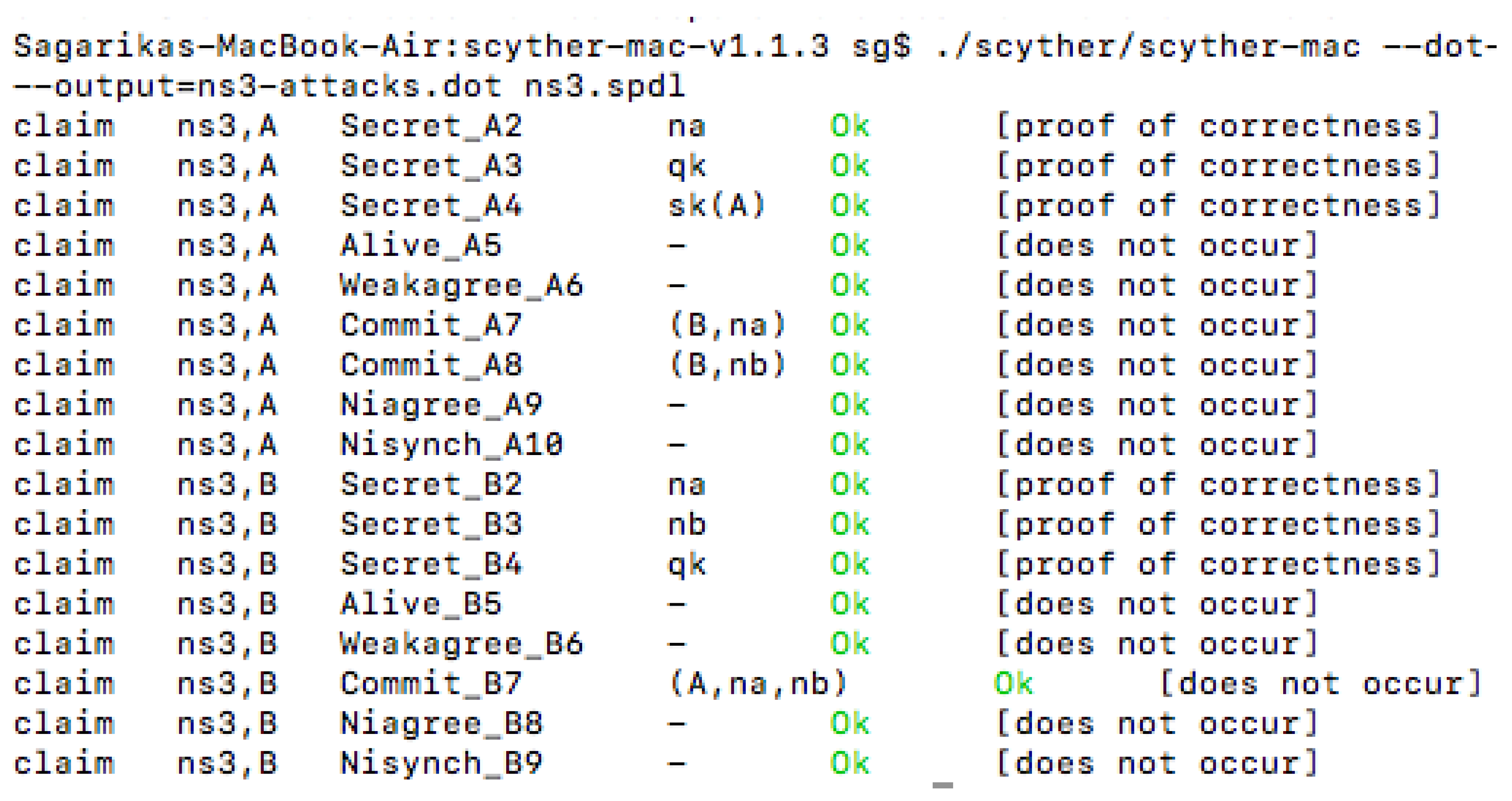
5.2. Modeling and Analysis of Classical Phase in Scyther

In this section, formal analysis of the classical part in the proposed signcryption scheme is presented which involves generating and exchanging encrypted data and digital signature altogether. We have used Scyther for the formal analysis of the non-quantum part of the proposed scheme. One of the properties we are testing is the secrecy of the quantum key and how it is affecting the secrecy of the encrypted data transferred.
Scyther is a tool that verifies traditional security and authentication protocols [44]. Using Scyther, two main properties are analyzed: Secrecy and Authentication [44].
Secrecy: The following assumptions are made [44]:
  • The sender or the receiver is communicating with a trusted party.
  • The sender and the receiver are communicating over an untrusted channel.
Authentication: The four factors that are assumed for the system are as follows [44]:
  • Aliveness: There is at least one communication partner in the network.
  • Synchronization: The intended party is aware of the authenticity of the other party to which it is communicating with.
  • The protocol is executing.
  • Message Agreement: The message sent by the sender is intact and not tampered. Thus, it has been exchanged as expected.
Furthermore, in the proposed signcryption model, we have used two keys. One, the quantum key is denoted as q k . The q k is used for the encryption of messages. Two, s k denotes the private key in the model. It is used to generate the digital signature. It provides authentication to the scheme. Both q k and s k are secret and private. Figure 4 and Figure 5 exhibit the verification results of a simple authentication protocol and the proposed signcryption scheme, respectively.
With Scyther as the security analysis tool, we have conducted a formal analysis of the signcrypted communication with the quantum and private keys. We have performed verification for the classical phase of the proposed scheme to provide motivation to move forward with the implementation phase. Figure 5 provides the result generated by Scyther when the quantum key is secret and not public. As per the result, the protocol successfully claims and passes the tests for security properties, which are mainly based on the following [45].
  • Secrecy of the keys and the cipher.
  • Commitment and aliveness of the two parties.
  • Synchronization of the communication between two parties.
  • Weak agreement property tests spoofing or man-in-the-middle (MiM) attack between the two parties. A weak agreement between two roles means there is no third-party spoofing or launching a MiM attack [45].
We performed verification for the classical phase of the proposed scheme to provide motivation to move forward toward the implementation phase.

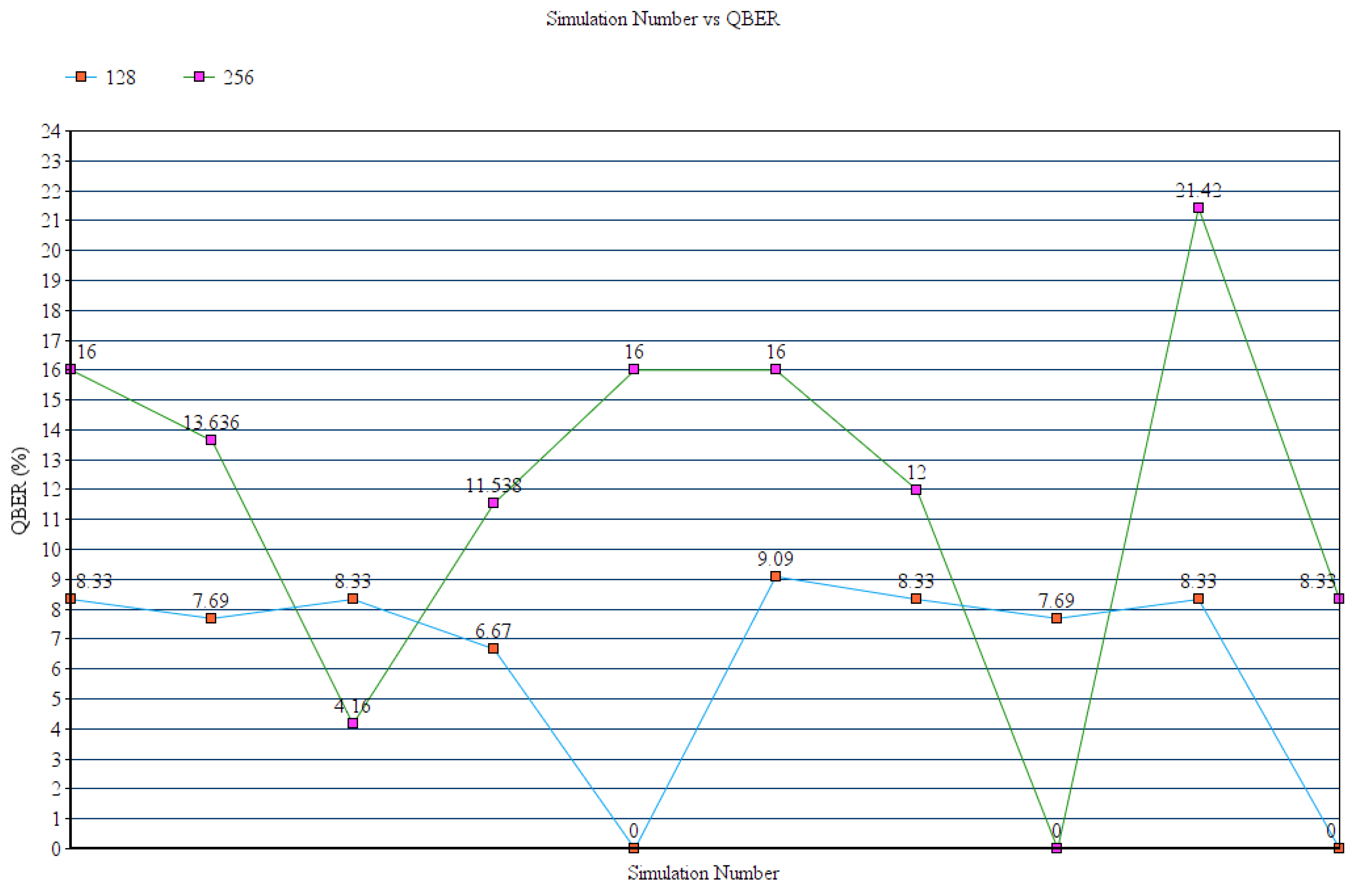
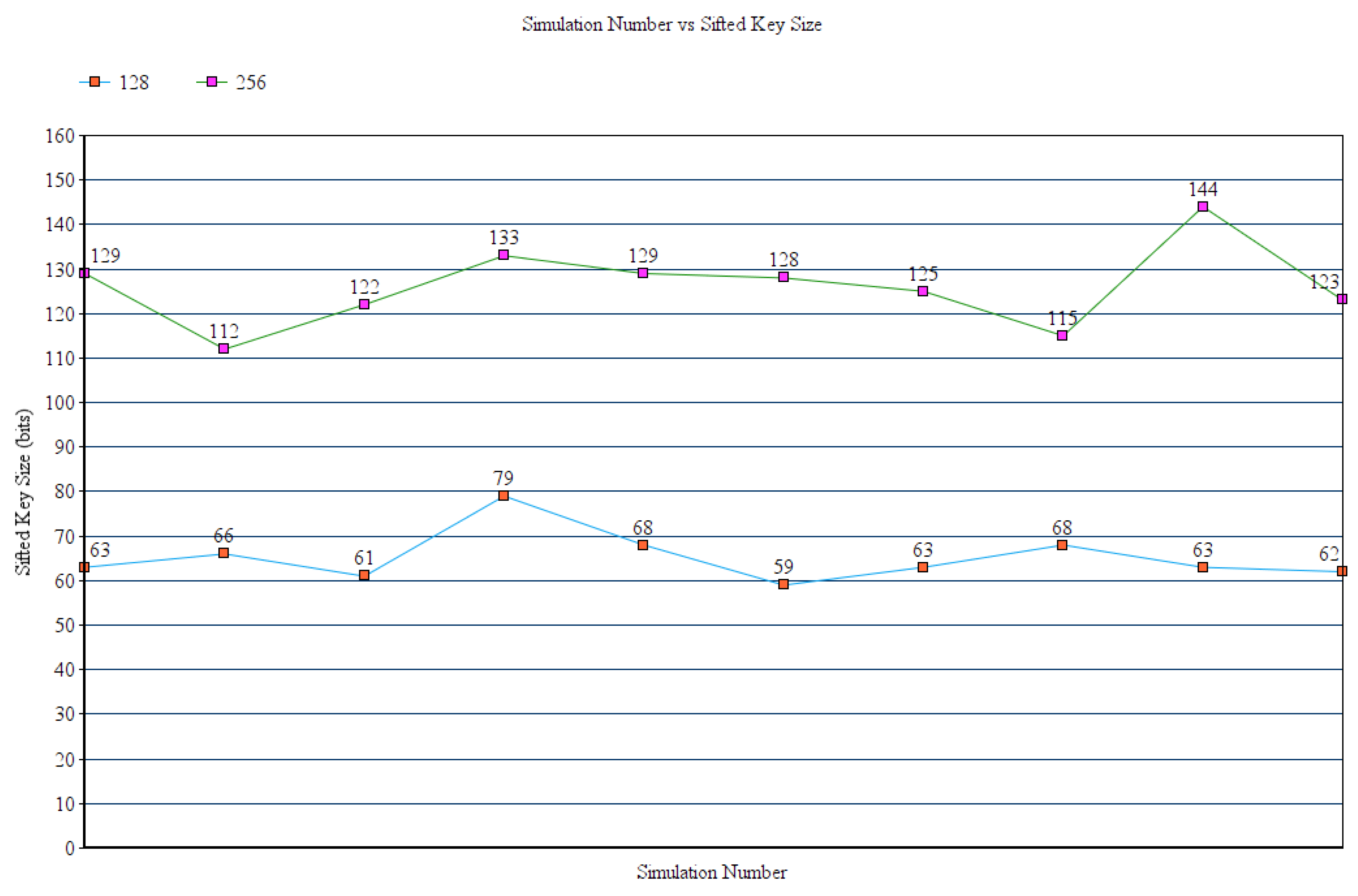
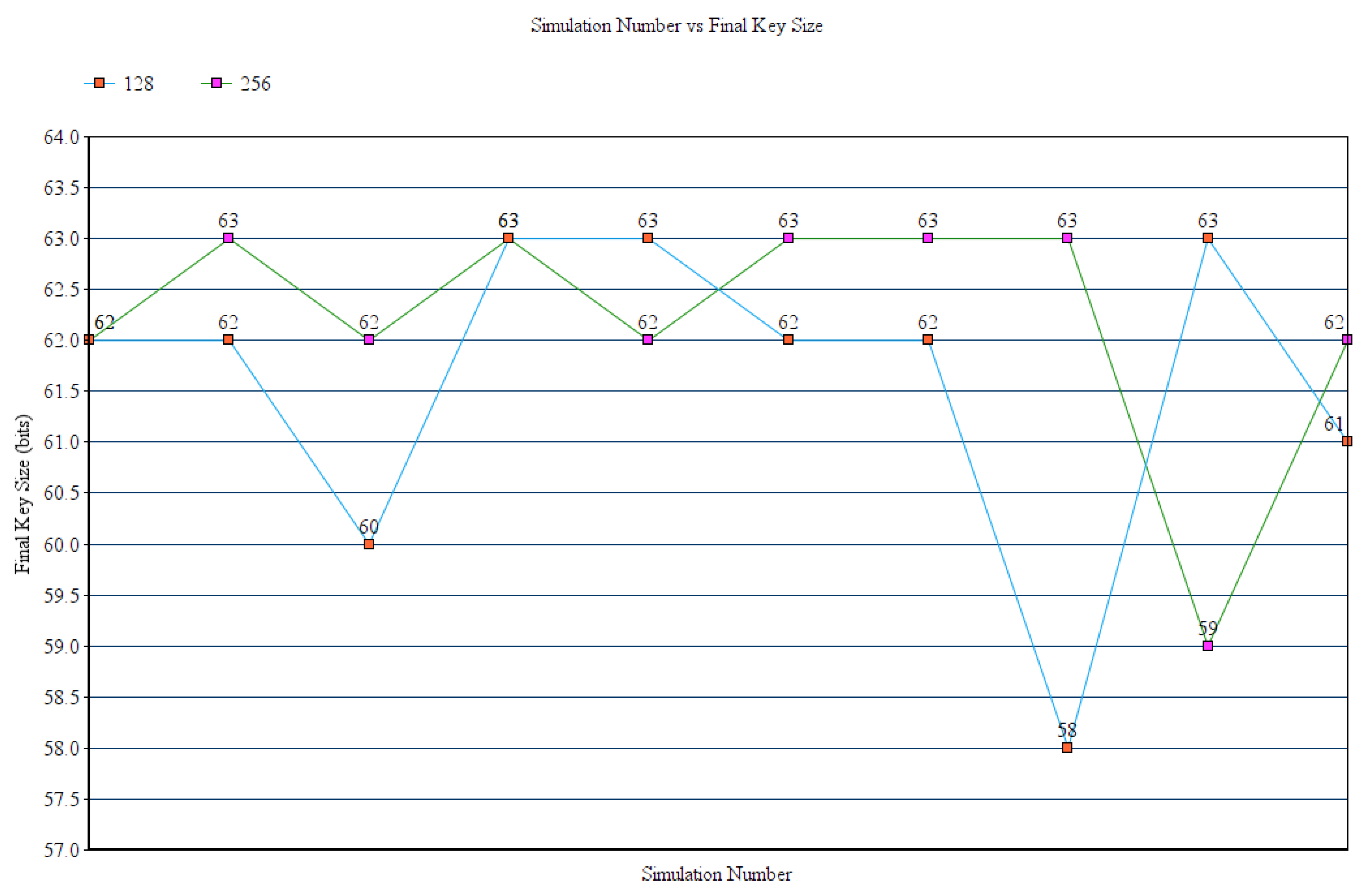
6. Experimental Results

We executed the proposed scheme in Python 3.6. We simulated the quantum channel with noise by designing a binary symmetric channel (BSC). In BSC, the sender sends a bit with value being either 0 or 1. The receiver receives that bit. However, there is a small probability that the bit is flipped in the channel [46].
To generate qubits and to measure their state, the Quantum Information Toolkit (QIT) has been used [47]. To implement the basis, two types of operators, namely, Pauli X operator and Hadamard operator, have been used [48].
Pauli X operator: It acts on a single qubit and flips its gate. It maps | 0 > to | 1 > and | 1 > to | 0 > .
Hadamard Operator: It provides the property of the Hadamard quantum gate. When it applies on a qubit with state | 0 > or | 1 > , there is an equal probability that the outcome state is either | 0 > or | 1 > . Furthermore, if the Hadamard gate applies twice on the same qubit, the final state is always the same as the initial state.

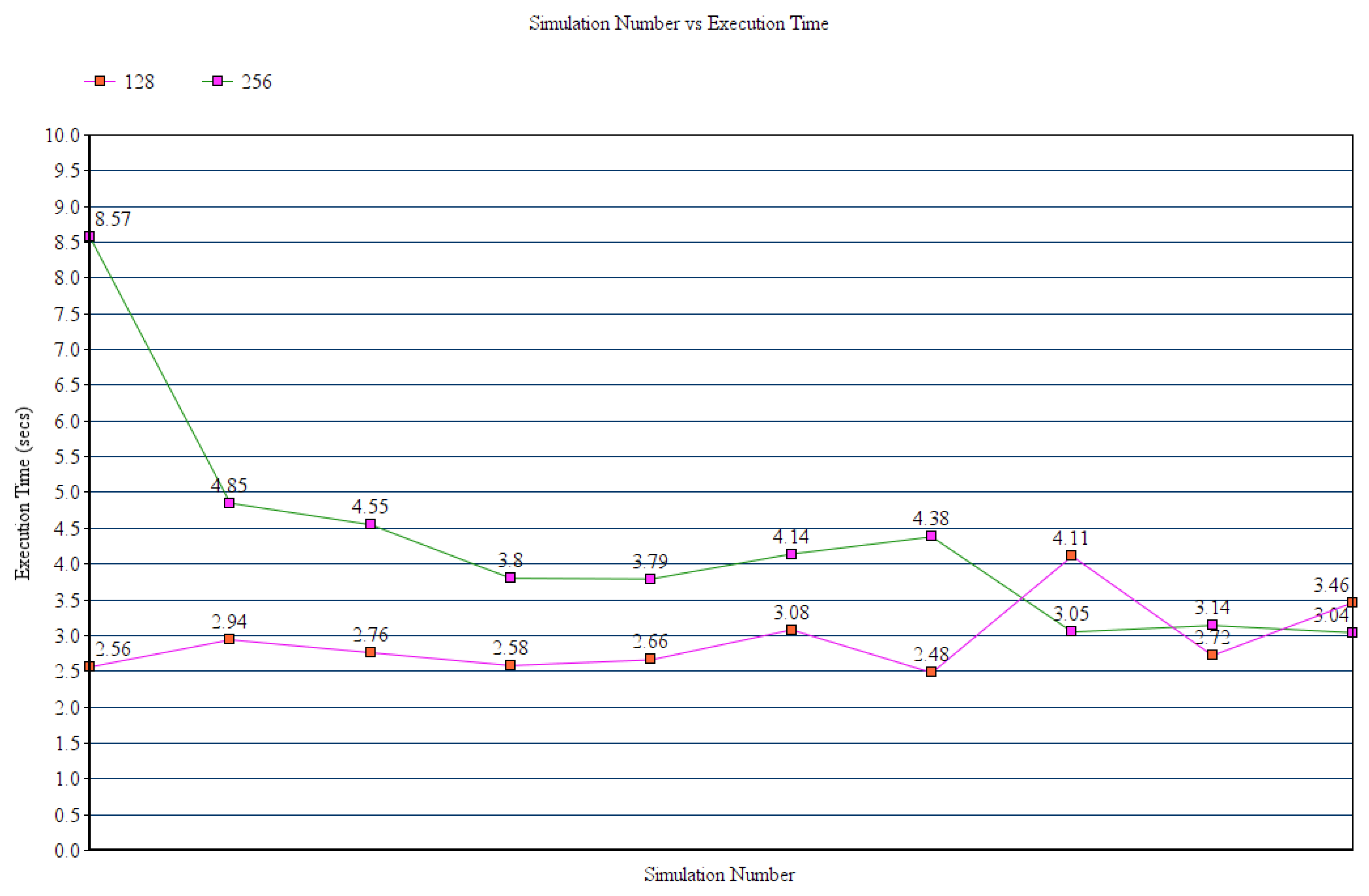
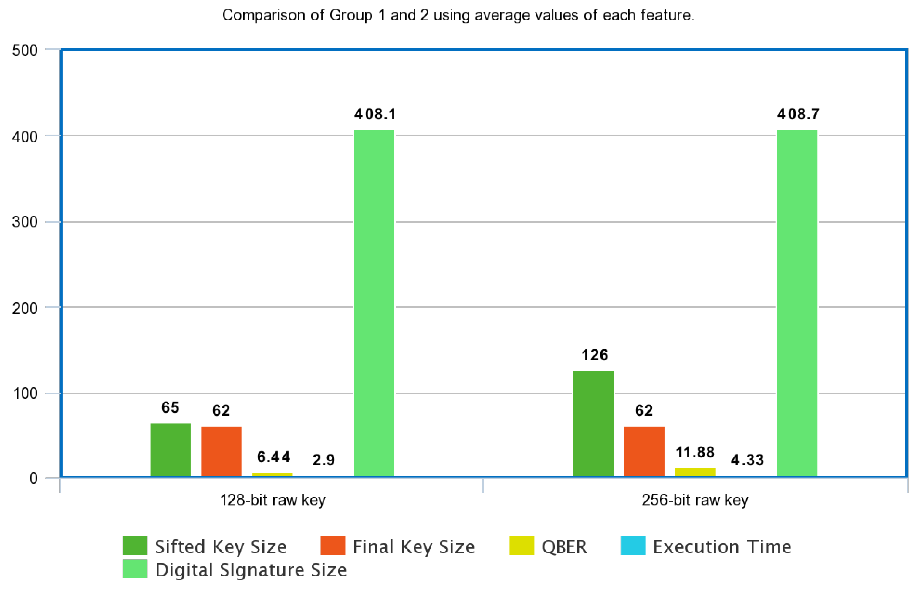
6.1. Comparative Analysis between 128-Bit BB84 vs. 256-BB84 Protocol

In evaluation testing, the simulation splits into two groups:
Group1:
It involves performing the proposed scheme on 128-bit initial or raw key.
Group2:
It involves performing the proposed scheme on 256-bit initial or raw key.
The simulation parameters of each group are as follows:
  • Error rate;
  • Sifted key size;
  • Final key size;
  • Execution time;
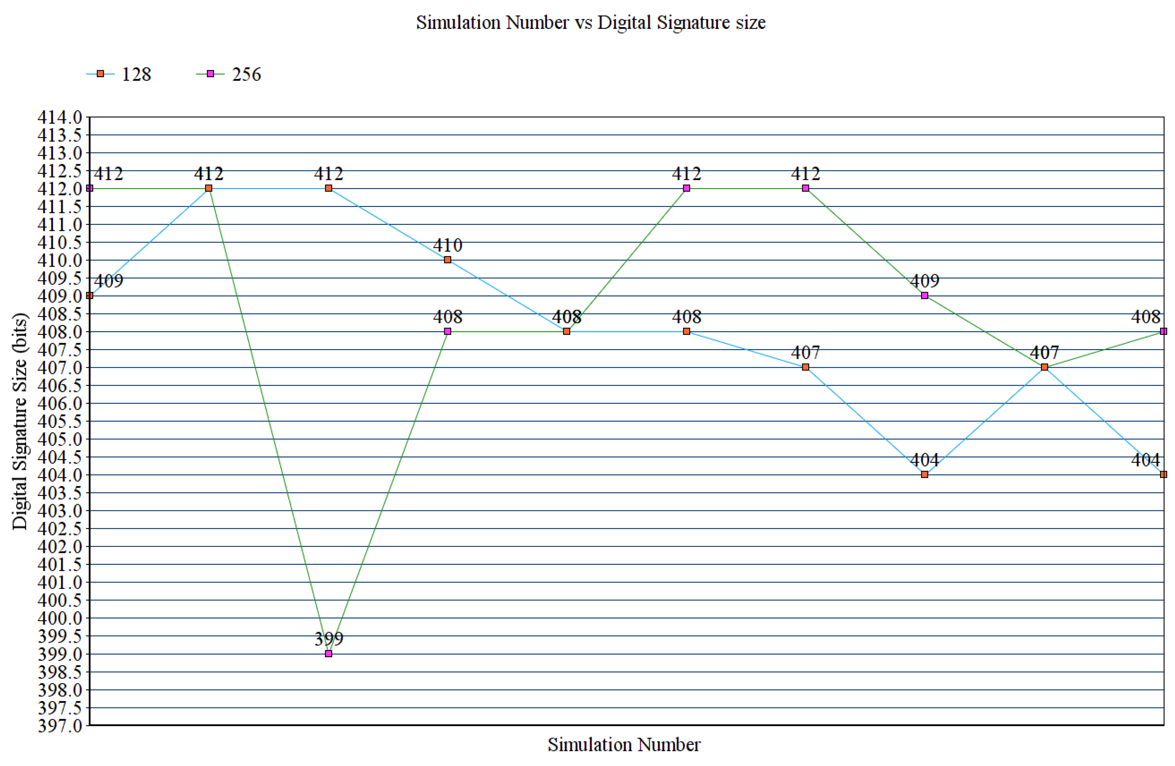
  • Digital signature size;
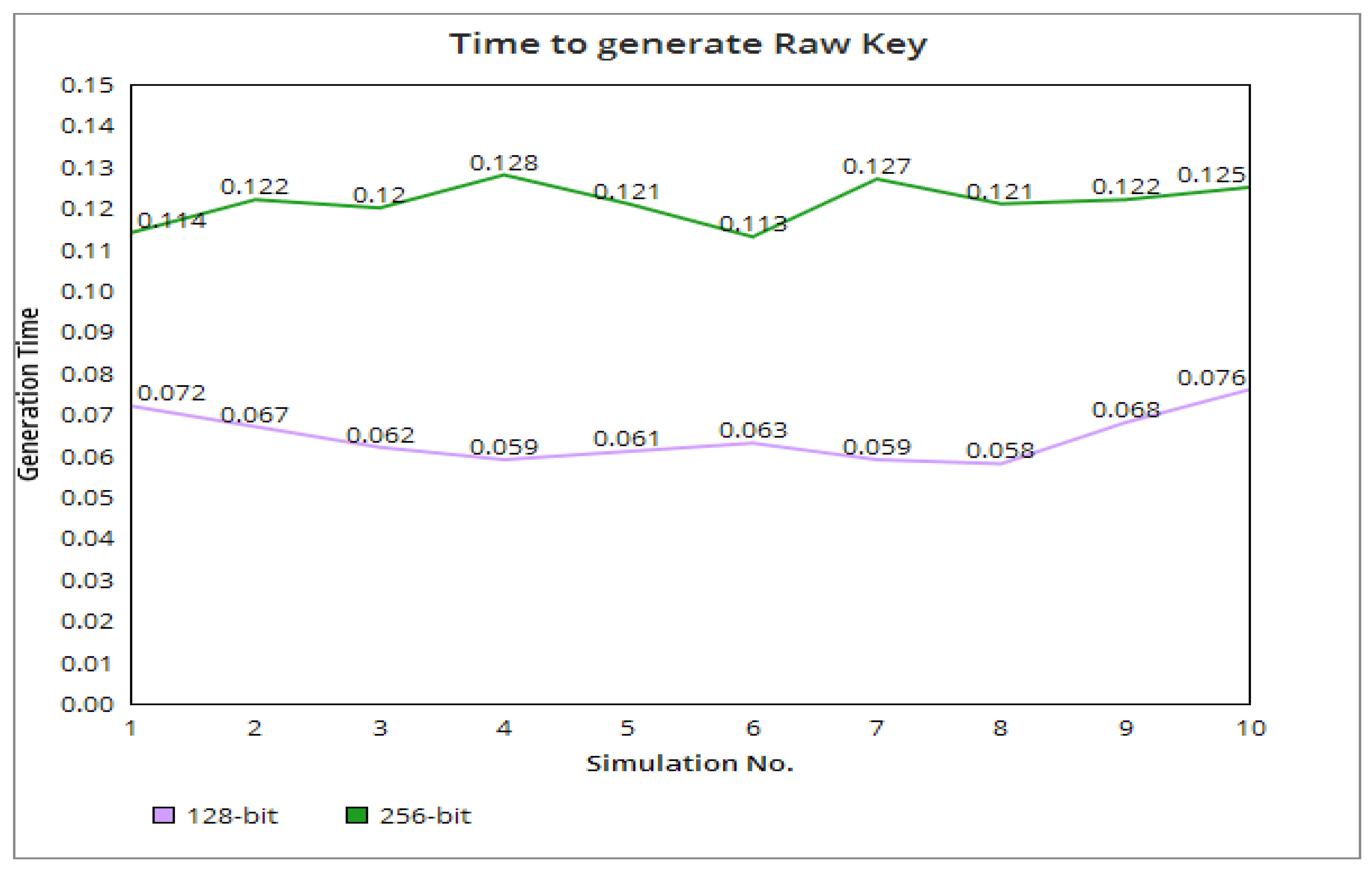
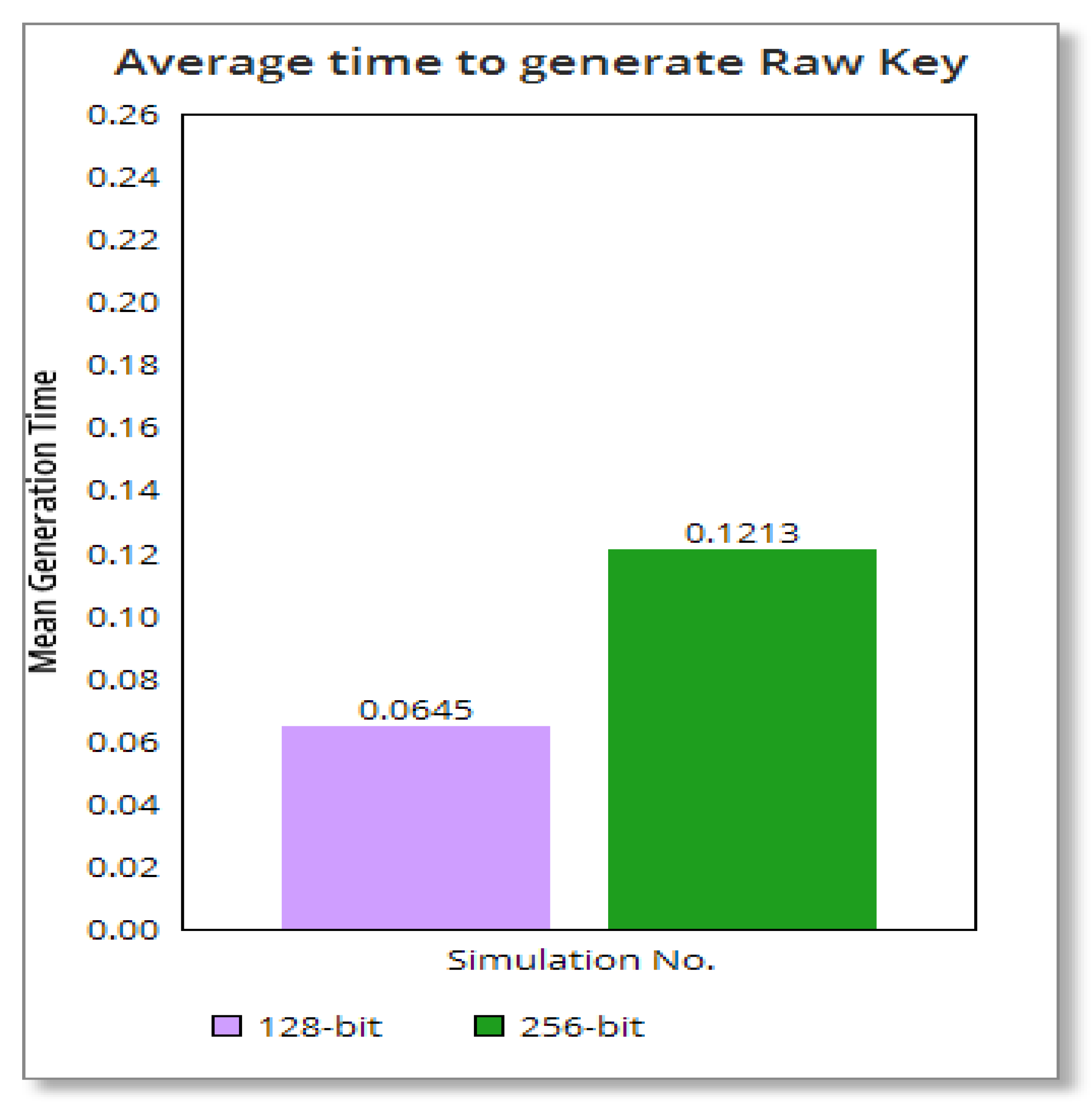
  • Time to generate a raw key.
Figure 6 illustrates the behavior of the scheme with 128-bit and 256-bit raw keys in terms of error rate. The coefficient of variation of this parameter for the 128-bit raw key is 0.507, and that of 256-bit is 0.502.
Figure 7 shows the behavior of the scheme with 128-bit and 256-bit raw keys in terms of sifted key size. The coefficient of variation of this parameter for the 128-bit and 256-bit is 0.082 and 0.062.
Figure 8 displays the behavior of the scheme with 128-bit and 256-bit raw keys in terms of final key size. The coefficient of variation of this parameter for the 128-bit and 256-bit is 0.024 and 0.018.
Figure 9 illustrates the behavior of the scheme with 128-bit and 256-bit raw keys in terms of digital signature size. The coefficient of variation of this parameter for the 128-bit and 256-bit is 0.0065 and 0.009.
Figure 10 explains the behavior of the scheme with 128-bit and 256-bit raw keys in terms of execution time.
Figure 11 displays the time to generate the raw keys or the initial keys. We observe that the generation time of the former is directly proportional to the generation time of the latter. It is more evident when we compare the mean values of the generation time of each group, as shown in Figure 12. For each data communication, the sender generates a new raw key and obtains the private and secret key. Therefore, the private key and secret key randomly vary in each communication.
Furthermore, Figure 13 illustrates the following behaviors.
  • The QBER evidently increases as the size of the raw key increases.
  • The sifted key size is directly proportional to the raw key size.
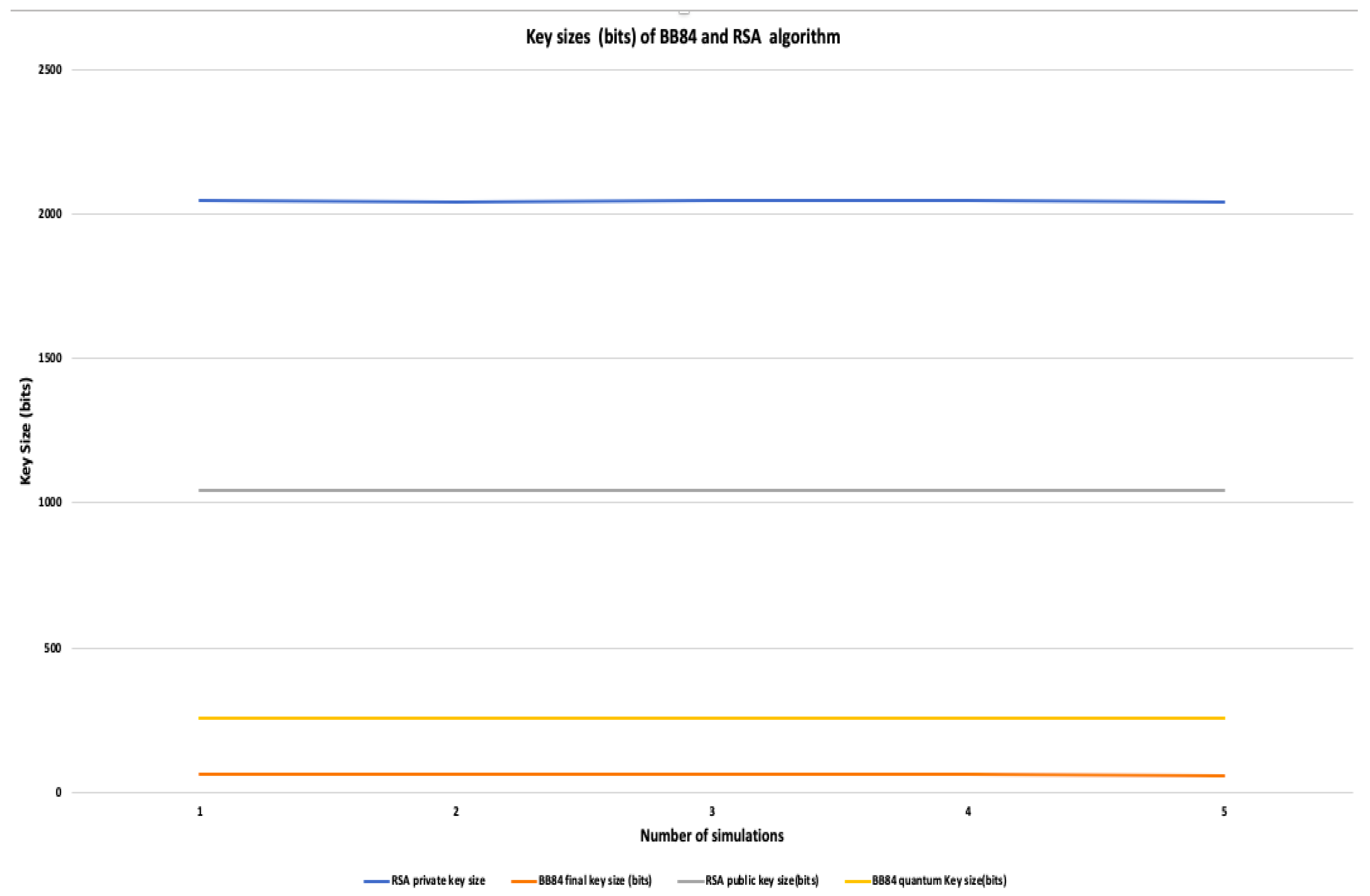
  • The final key size does not vary when the raw key size varies.
  • The digital signature size does not vary when when the raw key size is doubled.
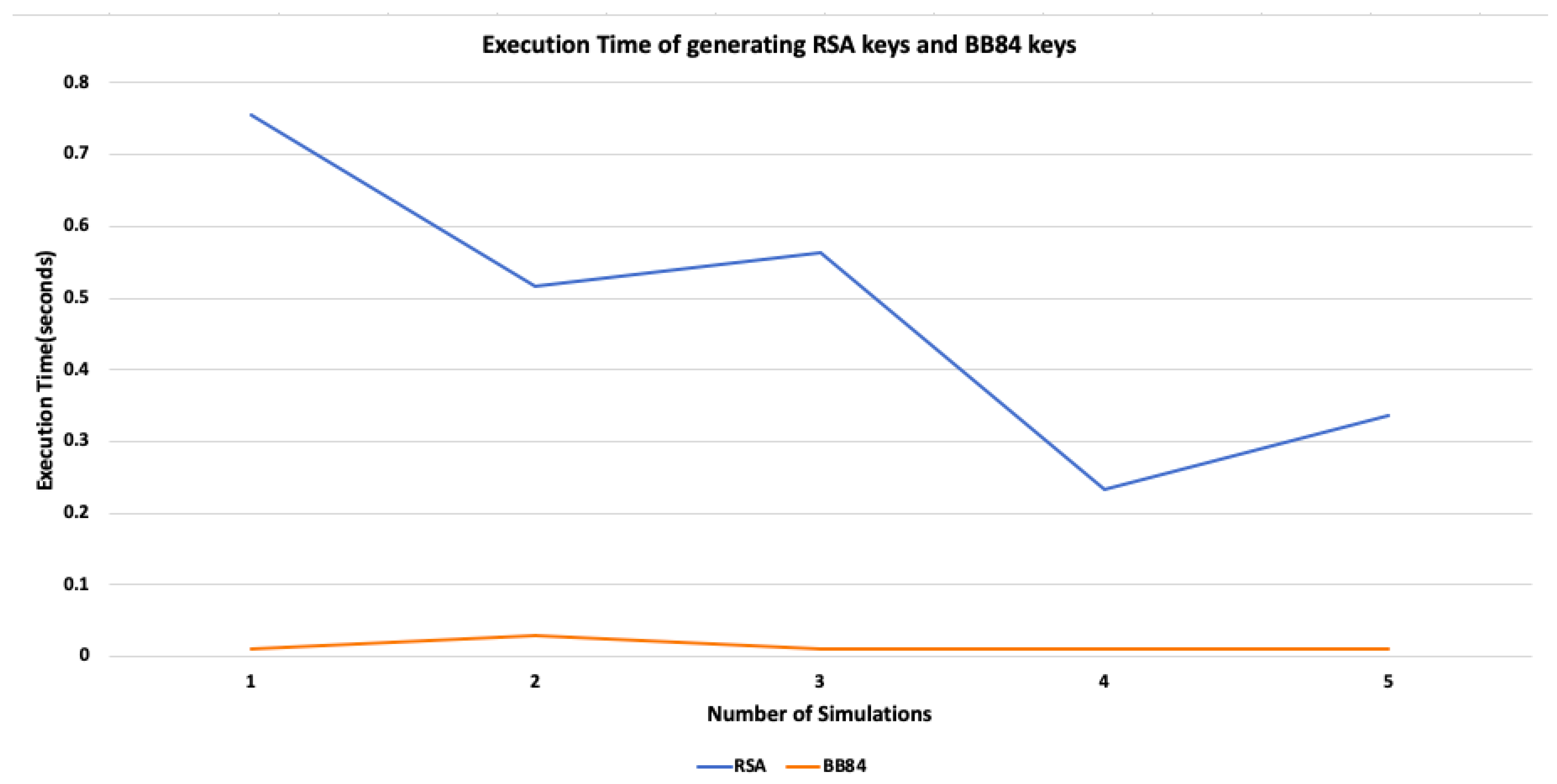
  • The execution time significantly changes when the raw key is adjusted.

6.2. Comparative Analysis between AGA-12 vs. Our Proposed Scheme

We have performed the comparative analysis between algorithms used in AGA-12 and our proposed scheme. Since the novelty of our proposed algorithm walks on Quantum Key Distribution protocol, we have used three variables for comparative analysis, mainly, key size, randomness of keys, and execution time.
We executed five simulations of both the algorithms, AGA-12, and our proposed scheme. We have measured the BB84 raw key size, final key size, RSA public key size, and RSA private key size. The average raw key size is 256 bits, and, the final key size of BB84 is approximately 62 bits. The RSA public key size is 1041 bits, and the private key size is around 2048 bits. Figure 14 shows a graph visualizing the difference between the key sizes of each algorithm.
We fed the five keys of BB84 and the RSA algorithm used in AGA-12 to the NIST statistical test suite for randomness. We have analyzed the randomness of the keys based on the appropriate NIST randomness test. Figure 15 shows the percentage of tests passed by both RSA and BB84 keys. We observed that the RSA public key, 1041 bits, passed 98% and the RSA private key, average size 2048 bits, passed 90% of the randomness tests while BB84 raw and final keys have passed 100% of the tests. Moreover, we have also compared the execution time of generating RSA keys and BB84 keys. Figure 16 shows a graph that shows the difference between the execution time to produce keys by the RSA and BB84 algorithms. The mean execution time of generating BB84 keys is 0.014554 s, and that of generating RSA keys is 0.4805578 s.

6.3. Challenges of Implementing a QKD to SCADA Networks

Our proposed algorithm secures the communication link between RTU and MTU, which is a point-to-point link. A QKD, on the other hand, on a network topology requires two channels, mainly quantum channel (fiber optic) or classical channel (Internet or fiber optic) [4]. Considering hardwired communication, a QKD in the SCADA network topology need 2 × n fiber optics, n being the traditional number of fiber optics [49]. Furthermore, if one of the channels is broken, the entire network shuts down. However, as future research work, a quantum channel can be designed to exchange both qubits and bits of data. Therefore, it will decline the number of fiber optics required in the SCADA network [49].

7. Conclusions

In this paper, we have proposed a novel security scheme which uses the properties of quantum physics to provide the following benefits to SCADA networks.
  • It resists not only the attacks of traditional computers but also quantum computers using Shor’s algorithm. It also defends against man-in-the-middle attack.
  • It is an encryption algorithm which also acts as an intrusion detection system.
  • The scheme adds authentication to the communications between units.
  • It does not rely on any third party for key generation and authentication.
Our proposed scheme attains all the security goals of integrity, confidentiality, availability, authentication, and non-repudiation. The randomness property of the key and its size enhances the security of the protocol. It uses uncertainty and superposition properties of quantum physics to detect any eavesdropping. Thus, compared to other traditional security schemes, it acts as an encryption as well as an intrusion detection scheme without relying on a third party. Therefore, it reduces the computational cost.
As a part of our future work, we will improve our proposed scheme by mainly working on the digital signature algorithm. We also intend to perform a comparative analysis of the AGA-12 digital signature and our proposed scheme. Additionally, we will conduct a comparative study by implementing various hash functions in the signature scheme and find out which yields the most potent hash. Our proposed scheme focuses on MiM attack and one quantum attack: brute-force attack using Shor’s algorithm. However, an eavesdropper can use the properties of quantum mechanics to launch probe attacks on Quantum Key Distribution [50,51]. In our future work, we will focus on these types of attacks, mainly, entangling-probe [50] and Fuchs–Peres–Brandt (FPB) probe attack [45,51]. In future work, we will perform a comparative analysis of our proposed quantum-based signcryption with post-quantum security hybrid signcryption. Wang et al. [52] have proposed a quantum secure signcryption that involves the extension of signcryption to lattice cryptography. However, our algorithm is based on exploiting the fundamentals of quantum computing and extending signcryption to quantum cryptography.

Author Contributions

S.G.: conceptualization, formal analysis, methodology, writing—first draft; M.Z.: project administration, writing—review and editing; B.P.: project administration, writing—review and editing, S.S.: funding acquisition, supervision, writing—review and editing. All authors have read and agreed to the published version of the manuscript.

Funding

The authors gratefully acknowledge the support in part by the Natural Sciences and Engineering Research Council (NSERC) and industry partners Cistel Technology Inc., through a Collaborative Research Grant.

Data Availability Statement

Not applicable.

Acknowledgments

Thanks to Rohit Joshi of Cistel Technologies for his valuable feedback.

Conflicts of Interest

The authors declare no conflict of interest.

References

  1. Nader, P.; Honeine, P.; Beauseroy, P. lp-norms in one-class classification for intrusion detection in SCADA systems. IEEE Trans. Ind. Inform. 2014, 10, 2308–2317. [Google Scholar] [CrossRef]
  2. Saputra, H.; Zhao, Z. Long term key management architecture for SCADA systems. In Proceedings of the 2018 IEEE 4th World Forum on Internet of Things (WF-IoT), Singapore, 5–8 February 2018; pp. 314–319. [Google Scholar] [CrossRef]
  3. Choi, D.; Kim, H.; Won, D.; Kim, S. Advanced Key-Management Architecture for Secure SCADA Communications. IEEE Trans. Power Deliv. 2009, 24, 1154–1163. [Google Scholar] [CrossRef]
  4. Ghosh, S.; Sampalli, S. A Survey of Security in SCADA Networks: Current Issues and Future Challenges. IEEE Access 2019, 7, 135812–135831. [Google Scholar] [CrossRef]
  5. Kang, D.J.; Lee, J.J.; Kim, S.J.; Park, J.H. Analysis on cyber threats to SCADA systems. In Proceedings of the 2009 Transmission & Distribution Conference & Exposition: Asia and Pacific, Seoul, Korea, 26–30 October 2009; IEEE: New York, NY, USA, 2009; pp. 1–4. [Google Scholar]
  6. Lomonaco, S. Shor’s quantum factoring algorithm. In Proceedings of the Symposia in Applied Mathematics, San Diego, CA, USA, 4–5 January 2002; Volume 58, pp. 161–180. [Google Scholar]
  7. Grover, L.K. A fast quantum mechanical algorithm for database search. In Proceedings of the Twenty-Eighth Annual ACM Symposium on Theory of Computing, Philadelphia, PA, USA, 22–24 May 1996; pp. 212–219. [Google Scholar]
  8. Dennis, R. Quantum Computers Are the Most Powerful Tech Threat to Cryptocurrency. 2018. Available online: https://blog.icoalert.com/quantum-computers-are-the-most-powerful-tech-threat-cryptocurrency-will-face (accessed on 14 January 2019).
  9. Mavroeidis, V.; Vishi, K.; Zych, M.D.; Jøsang, A. The impact of quantum computing on present cryptography. arXiv 2018, arXiv:1804.00200. [Google Scholar] [CrossRef]
  10. Hosoyamada, A.; Sasaki, Y. Quantum collision attacks on reduced SHA-256 and SHA-512. In Proceedings of the Annual International Cryptology Conference, Online, 16–20 August 2021; Springer: Berlin, Germany, 2021; pp. 616–646. [Google Scholar]
  11. Sibson, P.; Erven, C.; Godfrey, M.; Miki, S.; Yamashita, T.; Fujiwara, M.; Sasaki, M.; Terai, H.; Tanner, M.G.; Natarajan, C.M.; et al. Chip-based quantum key distribution. Nat. Commun. 2017, 8, 13984. [Google Scholar] [CrossRef] [PubMed]
  12. Chandra, S.; Paira, S.; Alam, S.S.; Sanyal, G. A comparative survey of symmetric and asymmetric key cryptography. In Proceedings of the 2014 International Conference on Electronics, Communication and Computational Engineering (ICECCE), Hosur, India, 17–18 November 2014; IEEE: New York, NY, USA, 2014; pp. 83–93. [Google Scholar]
  13. Zhang, X.; Dong, Z.Y.; Wang, Z.; Xiao, C.; Luo, F. Quantum cryptography based cyber-physical security technology for smart grids. In Proceedings of the 10th International Conference on Advances in Power System Control, Operation & Management (APSCOM 2015), Hong Kong, China, 8–12 November 2015. [Google Scholar]
  14. Busch, P.; Heinonen, T.; Lahti, P. Heisenberg’s uncertainty principle. Phys. Rep. 2007, 452, 155–176. [Google Scholar] [CrossRef]
  15. Sinha, A.; Vijay, A.H.; Sinha, U. On the superposition principle in interference experiments. Sci. Rep. 2015, 5, 10304. [Google Scholar] [CrossRef]
  16. Bužek, V.; Hillery, M. Quantum copying: Beyond the no-cloning theorem. Phys. Rev. A 1996, 54, 1844. [Google Scholar] [CrossRef]
  17. Johnson, J.S.; Grimaila, M.R.; Humphries, J.W.; Baumgartner, G.B. An analysis of error reconciliation protocols used in quantum key distribution systems. J. Def. Model. Simul. 2015, 12, 217–227. [Google Scholar] [CrossRef]
  18. Portugal, R. Quantum Walks and Search Algorithms; Springer: Berlin, Germany, 2013. [Google Scholar]
  19. Hwang, R.J.; Lai, C.H.; Su, F.F. An efficient signcryption scheme with forward secrecy based on elliptic curve. Appl. Math. Comput. 2005, 167, 870–881. [Google Scholar] [CrossRef]
  20. Zaverucha, G.M.; Stinson, D.R. Short one-time signatures. Adv. Math. Commun. 2011, 5, 473. [Google Scholar]
  21. Yan, H.; Peng, X.; Lin, X.; Jiang, W.; Liu, T.; Guo, H. Efficiency of Winnow protocol in secret key reconciliation. In Proceedings of the 2009 WRI World Congress on Computer Science and Information Engineering, Los Angeles, CA, USA, 31 March–2 April 2009; IEEE: New York, NY, USA, 2009; Volume 3, pp. 238–242. [Google Scholar]
  22. Singh, V.; Sharma, N. A Review on Various Error Detection and Correction Methods Used in Communication. Am. Int. J. Res. Sci. Technol. Eng. Math. 2015, 15, 252–257. [Google Scholar]
  23. Alabady, S.A.; Al-Turjman, F. Low complexity parity check code for futuristic wireless networks applications. IEEE Access 2018, 6, 18398–18407. [Google Scholar] [CrossRef]
  24. Choudhari, S.P.; Chakole, M.B. Reed solomon code for WiMAX network. In Proceedings of the 2017 International Conference on Communication and Signal Processing (ICCSP), Melmaruvathur, India, 6–8 April 2017; IEEE: New York, NY, USA, 2017; pp. 0176–0179. [Google Scholar]
  25. Lu, X.; Feng, D. Quantum digital signature based on quantum one-way functions. In Proceedings of the 7th International Conference on Advanced Communication Technology, ICACT 2005, Phoenix Park, Korea, 21–23 February 2005; IEEE: New York, NY, USA, 2005; Volume 1, pp. 514–517. [Google Scholar]
  26. Abdullah, G.M.; Mehmood, Q.; Khan, C.B.A. Adoption of Lamport signature scheme to implement digital signatures in IoT. In Proceedings of the 2018 International Conference on Computing, Mathematics and Engineering Technologies (iCoMET), Sukkur, Pakistan, 3–4 March 2018; IEEE: New York, NY, USA, 2018; pp. 1–4. [Google Scholar]
  27. Cleary, F.; Felici, M. Cyber Security and Privacy: 4th Cyber Security and Privacy Innovation Forum, CSP Innovation Forum 2015, Brussels, Belgium April 28–29, 2015, Revised Selected Papers; Springer: Berlin, Germany, 2015; Volume 530. [Google Scholar]
  28. Ponomarev, S.; Atkison, T. Industrial control system network intrusion detection by telemetry analysis. IEEE Trans. Dependable Secur. Comput. 2015, 13, 252–260. [Google Scholar] [CrossRef]
  29. ICS Advisory (ICSA-10-201-01C). Available online: https://www.cisa.gov/uscert/ics/advisories/ICSA-10-201-01C. (accessed on 15 January 2019).
  30. Carcano, A.; Coletta, A.; Guglielmi, M.; Masera, M.; Fovino, I.N.; Trombetta, A. A multidimensional critical state analysis for detecting intrusions in SCADA systems. IEEE Trans. Ind. Inform. 2011, 7, 179–186. [Google Scholar] [CrossRef]
  31. Ponomarev, S.; Wallace, N.; Atkison, T. Detection of ssh host spoofing in control systems through network telemetry analysis. In Proceedings of the 9th Annual Cyber and Information Security Research Conference, Oak Ridge, TN, USA, 8–10 April 2014; pp. 21–24. [Google Scholar]
  32. Cekerevac, Z.; Dvorak, Z.; Prigoda, L.; Cekerevac, P. Internet of things and the man-in-the-middle attacks-security and economic risks. MEST J. 2017, 5, 15–25. [Google Scholar] [CrossRef]
  33. Gidney, C.; Ekerå, M. How to factor 2048 bit RSA integers in 8 h using 20 million noisy qubits. arXiv 2019, arXiv:1905.09749. [Google Scholar] [CrossRef]
  34. Karati, A.; Fan, C.I.; Hsu, R.H. Provably Secure and Generalized Signcryption with Public Verifiability for Secure Data Transmission Between Resource-Constrained IoT Devices. IEEE Internet Things J. 2019, 6, 10431–10440. [Google Scholar] [CrossRef]
  35. Fröhlich, B.; Lucamarini, M.; Dynes, J.F.; Comandar, L.C.; Tam, W.W.S.; Plews, A.; Sharpe, A.W.; Yuan, Z.; Shields, A.J. Long-distance quantum key distribution secure against coherent attacks. Optica 2017, 4, 163–167. [Google Scholar] [CrossRef]
  36. Routray, S.K.; Jha, M.K.; Sharma, L.; Nyamangoudar, R.; Javali, A.; Sarkar, S. Quantum cryptography for IoT: APerspective. In Proceedings of the 2017 International Conference on IoT and Application (ICIOT), Nagapattinam, India, 19–20 May 2017; IEEE: New York, NY, USA, 2017; pp. 1–4. [Google Scholar]
  37. Kumar, A.; Garhwal, S. State-of-the-Art Survey of Quantum Cryptography. Arch. Comput. Methods Eng. 2021, 28, 3831–3868. [Google Scholar] [CrossRef]
  38. Sun, S.; Huang, A. A review of security evaluation of practical quantum key distribution system. Entropy 2022, 24, 260. [Google Scholar] [CrossRef] [PubMed]
  39. Bennett, C.H.; Brassard, G. Quantum cryptography: Public key distribution and coin tossing. Theor. Comput. Sci. 2014, 560, 7–11. [Google Scholar] [CrossRef]
  40. Riley, M.; Richardson, I. An Introduction to Reed-Solomon Codes: Principles, Architecture and Implementation.2003. Available online: https://www.cs.cmu.edu/~guyb/realworld/reedsolomon/reed_solomon_codes.html (accessed on 30 August 2020).
  41. Soykan, E.U.; Ersoz, S.D.; Soykan, G. Identity based signcryption for advanced metering infrastructure. In Proceedings of the 2015 3rd International Istanbul Smart Grid Congress and Fair (ICSG), Istanbul Turkey, 29–30 April 2015; IEEE: New York, NY, USA, 2015; pp. 1–5. [Google Scholar]
  42. Papanikolaou, N.K. Techniques for Design and Validation of Quantum Protocols. Master’s Thesis, University of Warwick, Coventry, UK, 2005. [Google Scholar]
  43. Kuppam, S. Modelling of Quantum Key Distribution Protocols in Communicating Quantum Processes Language with Verification and Analysis in PRISM. In Proceedings of the SIMULTECH 2018: 8th International Conference on Simulation and Modeling Methodologies, Technologies and Applications, Porto, Portugal, 29–31 July 2018; pp. 75–82. [Google Scholar]
  44. Cremers, C.; Mauw, S. Operational semantics of security protocols. In Scenarios: Models, Transformations and Tools; Springer: Berlin/Heidelberg, Germany, 2005; pp. 66–89. [Google Scholar]
  45. Lowe, G. A hierarchy of authentication specifications. In Proceedings of the 10th Computer Security Foundations Workshop, Rockport, MA, USA, 10–12 June 1997; IEEE: New York, NY, USA, 1997; pp. 31–43. [Google Scholar]
  46. Victoria, U. coding515.pdf—ECE 515 Information Theory Channel Capacity and Coding 1 Information Theory Problems How to Transmit or Store Information as Efficiently. 2016. Available online: https://www.coursehero.com/file/35896396/coding515pdf/ (accessed on 7 June 2019).
  47. Quantum Information Toolkit—Quantum Information Toolkit 0.11.0 Documentation. Available online: http://qit.sourceforge.net/docs/html/ (accessed on 7 June 2019).
  48. Williams, C.P. Quantum Gates. In Explorations in Quantum Computing; Texts in Computer Science; Springer: London, UK, 2011; pp. 1–5. [Google Scholar]
  49. Ghosh, S.; Zaman, M.; Sakauye, G.; Sampalli, S. An Intrusion Resistant SCADA Framework Based on Quantum and Post-Quantum Scheme. Appl. Sci. 2021, 11, 2082. [Google Scholar] [CrossRef]
  50. Azuma, H. An entangling-probe attack on Shor’s algorithm for factorization. J. Mod. Opt. 2018, 65, 415–422. [Google Scholar] [CrossRef]
  51. Shapiro, J.H.; Wong, F.N. Attacking quantum key distribution with single-photon two-qubit quantum logic. Phys. Rev. A 2006, 73, 012315. [Google Scholar] [CrossRef]
  52. Wang, F.; Hu, Y.; Wang, C. Post-quantum secure hybrid signcryption from lattice assumption. Appl. Math. Inf. Sci. 2012, 6, 23–28. [Google Scholar]
Figure 1. Hamming code structure (P4, P2 and P1 are parity bits. The rest are data bits).
Symmetry 14 01625 g001
Figure 2. The proposed scheme model.
Symmetry 14 01625 g002
Figure 3. Operations of RTU (sender). The signcrypted message is sent to sub-MTU/MTU (receiver).
Symmetry 14 01625 g003
Figure 4. Verification results of a simple authentication protocol.
Symmetry 14 01625 g004
Figure 5. Verification results of the proposed Signcryption scheme.
Symmetry 14 01625 g005
Figure 6. Simulation number vs. QBER.
Symmetry 14 01625 g006
Figure 7. Simulation number vs. sifted key size.
Symmetry 14 01625 g007
Figure 8. Simulation number vs. final key size.
Symmetry 14 01625 g008
Figure 9. Simulation number vs. digital signature size.
Symmetry 14 01625 g009
Figure 10. Simulation number vs. execution time.
Symmetry 14 01625 g010
Figure 11. Simulation number vs. time to generate raw key (generation time).
Symmetry 14 01625 g011
Figure 12. Comparison of Group 1: 128-bit raw key vs. Group 2: 256-bit raw key, using the mean value of generation time of each group.
Symmetry 14 01625 g012
Figure 13. Comparison of Group 1: 128-bit raw key vs. Group 2: 256-bit raw key, using the mean value of each feature.
Symmetry 14 01625 g013
Figure 14. Comparison of RSA keys vs. BB84 keys over 5 simulations.
Symmetry 14 01625 g014
Figure 15. Comparison of percentage of passed NIST tests for randomness of BB84 and RSA keys.
Symmetry 14 01625 g015
Figure 16. Comparison of execution time of generating RSA keys used in AGA-12 and BB84 keys used in proposed scheme.
Symmetry 14 01625 g016
Table 1. Terminology of basic concepts in quantum cryptography.
TermDescription
Traditional or Classical CryptographyIt is a type of cryptography that is based on mathematical computation that uses a single communication channel [12].
Quantum CryptographyCryptography dependent on the principles of quantum mechanics and two channels, namely, quantum and public channels [13].
Heisenberg’s Uncertainty PrincipleThis principle states that it is not possible to obtain the position and momentum of a photon with absolute accuracy [14].
Principle of Photon PolarizationThis principle states that a photon can have a superposition of two or more quantum states at a time [15].
No-Cloning TheoremThis theorem states that one cannot produce an identical copy of an arbitrary quantum state of a photon [16].
Quantum Bit Error Rate (QBER)QBER is the fraction of mismatched qubits exchanged between the sender and the receiver [13].
Error Correction Code (ECC)ECC is an algorithm that detects and corrects errors in transmitted data [17].
Quantum ChannelQuantum Channel exchanges qubits and can create noise in the presence of an intruder or due to environmental factors [13].
QubitQubit is a basic unit of data in quantum computing. It follows the properties of Principle of Photon polarization and Heisenberg’s Uncertainty Principle [13].
BasisBasis is a vector used to generate the superposed state of qubits [18].
SigncryptionAn authenticated encryption scheme to provide both confidentiality and authenticity [19].
One-Time Signature (OTS)OTS is based on hash-function that signs one message per key pair [20].
Table 2. Attacks on SCADA systems.
CLASSICAL ATTACKSDescription
Attack against
Confidentiality
Packet SniffingThe intruder intercepts the incoming and outgoing traffic in a network and fetches sensitive information by decoding the data packets. By using Wireshark and Tcpdump, sniffing can be attained.
EavesdropThe intruder can install an eavesdropping equipment in the wired or wireless network between the RTU and MTU. The ongoing conversations can be wiretapped. Tools that can be used include Wireshark and dnsiff.
Attack against IntegrityMan-in-the-middle attack (MiM)In an MiM attack, the intruder monitors the traffic between the two nodes. The data packets traded between two victim nodes are captured. The intruder then injects abnormal data during the transmission and sends it to the receiver. It can launch IP spoofing and a Session Hijacking attack. A few tools that are used to launch MiM attack are Ettercap, SSLStrip and Evilgrade.
Session HijackingAfter a successful MiM attack, the intruder accesses the information and services in the MTU and RTU. It accesses the session ID and launches a replay attack. A few examples of tools are Ettercap and Evilgrade.
Data InjectionThe intruder can successfully alter the data after launching an MiM attack. A few tools that can be used are Wireshark and Ettercap.
Replay AttackThe attacker can launch a replay attack by performing session hijacking and IP spoofing. By imitating as a friendly unit and using the session ID, it stores the old data and sends it to other units later. Tools that can be used are Ettercap and Evilgrade.
Attack against AuthenticationMasqueradeBy using IP spoofing, the attacker uses a fake identity to pretend as a original unit and steals essential data from the system or the network. For example, it can fetch passwords and gain access to the system. Tools that can be used for launching this type of attack are Ettercap, Arpspoof and Brutus.
Attack against AvailabilityDenial of Service (DoS)This kind of attack occurs when a compromised unit is used to target a system by sending huge traffic or a large amount of junk data. A unit can be compromised in several ways after a successful MiM attack. The examples of DoS attack tools are Slowloris and GoldenEye.
QUANTUM ATTACK
Quantum AttackBrute Force Attack by a Quantum ComputerThe emergence of the quantum computer brings with it benefits as well as risks to the cyber field. A quantum computer is way faster and more efficient than traditional computers. Using Shor’s and Grover’s algorithm, a quantum computer can launch a brute force attack and crack the traditional encryption schemes in a brief time. One such problem is elliptic curve cryptography (ECC or ECDSA).
Table 3. Probability of detecting of Intercept–Resend eavesdropping when LUCKY is 0.5.
MODEL 1P1P2
N = 40.9380.145
N = 50.9690.155
N = 60.9840.065
N = 70.9920.067
N = 80.9960.028
LUCKY = 0.5
Table 4. Probability of detecting of Intercept–Resend eavesdropping when N is 5.
MODEL 1P1P2
L= 0.50.9680.155
L = 0.60.9680.174
L = 0.70.9680.193
L= 0.80.9680.285
N = 5
Table 5. Probability of detecting of Random-Substitute eavesdropping when Lucky is 0.5.
MODEL 1P1P2
N = 40.9380.145
N = 50.9690.155
N = 60.9840.065
N = 70.9920.067
N = 80.9960.028
LUCKY = 0.5
Table 6. Probability of detecting of Random-Substitute eavesdropping when N is 5.
MODEL 1P1P2
L= 0.50.9690.155
L = 0.60.9690.174
L = 0.70.9690.193
L= 0.80.9690.285
N = 5
Publisher’s Note: MDPI stays neutral with regard to jurisdictional claims in published maps and institutional affiliations.

