1. Introduction
In 2006, Chiu-Webster and Lister [
1] discovered and investigated the fascinating behavior of a viscous thread falling onto a translating surface. The phenomenon has attracted sustained attention since then and because a variety of intricate “stitching” patterns could be obtained—depending on the flow rate, fall height, the speed of the belt, and the material properties of the liquid—it was dubbed the fluid-mechanical sewing machine (FMSM).
The FMSM can be regarded as a generalization of the more familiar coiling effect, first described in detail by Barnes and Woodcock [
2]. The behavior of a viscous stream falling on a planar surface is itself a highly complex phenomenon which has only recently been understood to comprise four distinct modes, with the corresponding four scaling laws: viscous, gravitational, inertial-gravitational, and inertial [
3,
4,
5,
6]. Indeed, at belt speed zero, the FMSM “simply” becomes coiling instability. At increased belt speed, a phase space of FMSM patterns emerges that has been elucidated in detail experimentally [
7]. In order to rationalize experimental observations, numerous theoretical works explored the onset of stability of the falling thread [
8], also in the asymptotic limit of an extremely slender thread [
9], providing insights into the nature of the instability. Further numerical studies [
10,
11,
12] elucidated the sequence of bifurcations seen when the belt speed changes. A comprehensive review [
13] is included in this issue.
An aspect which has received scant attention thus far are the phenomena arising when, instead of falling from a stationary source onto a moving surface, the viscous thread’s source is translating and the stream falls onto a stationary substrate. The two scenarios are not equivalent. In the former case, the disturbance of the thread originates at the low end of the stream and propagates upwards; in the latter, the disturbance is imparted at the upper end and propagates downwards. The second scenario is, in fact, commonplace (think of maple syrup poured on toast) and has been identified in artistic explorations of abstract expressionist painter Jackson Pollock [
14], who poured viscous pigment while moving the source in the air above a horizontally stretched canvas—effectively painting in the air.
It should be emphasized that in all investigations of FMSM to date, the focus has been on the steady-state motion at a constant belt speed. In experimental studies, transitions from one fixed speed to another have clearly been observed and documented in numerous videos, but theoretical and numerical analyses have yet to address the case when the belt is accelerating.
The present contribution is a preliminary experimental investigation of a viscous thread falling on a rotating, rather than translating, platform. In this case, the stream is dragged by a moving surface, which is rotating about a fixed axis and is thus locally subject to centripetal acceleration. The situation has an interesting practical application. In Chinese culinary tradition, Shangdong pancake is a giant crispy crepe, 30–40 cm in diameter, which is made on a spinning wheel; during the process, sweet (and very viscous) syrup is sometimes poured, in a thin stream, over the pancake. The real motivation for this study, however, came from a suggestion, inspired by the FMSM, that Pollock’s painting technique could lead to novel artistic effects when inverted, so that a stream of viscous pigment issuing from a fixed source would be falling on a moving canvas. In such a case, a spinning circular canvas would be the most practical solution and the resulting painting would presumably be a tondo [
15].
The remainder of this paper is organized as follows. In
Section 2, the details of the experimental procedure are given. In
Section 3, selected recorded traces are presented for various groups of dimensionless parameters. In
Section 4, experimental results are compared to those obtained in previous FMSM experiments. Brief concluding remarks follow in
Section 5.
2. Experimental Setup
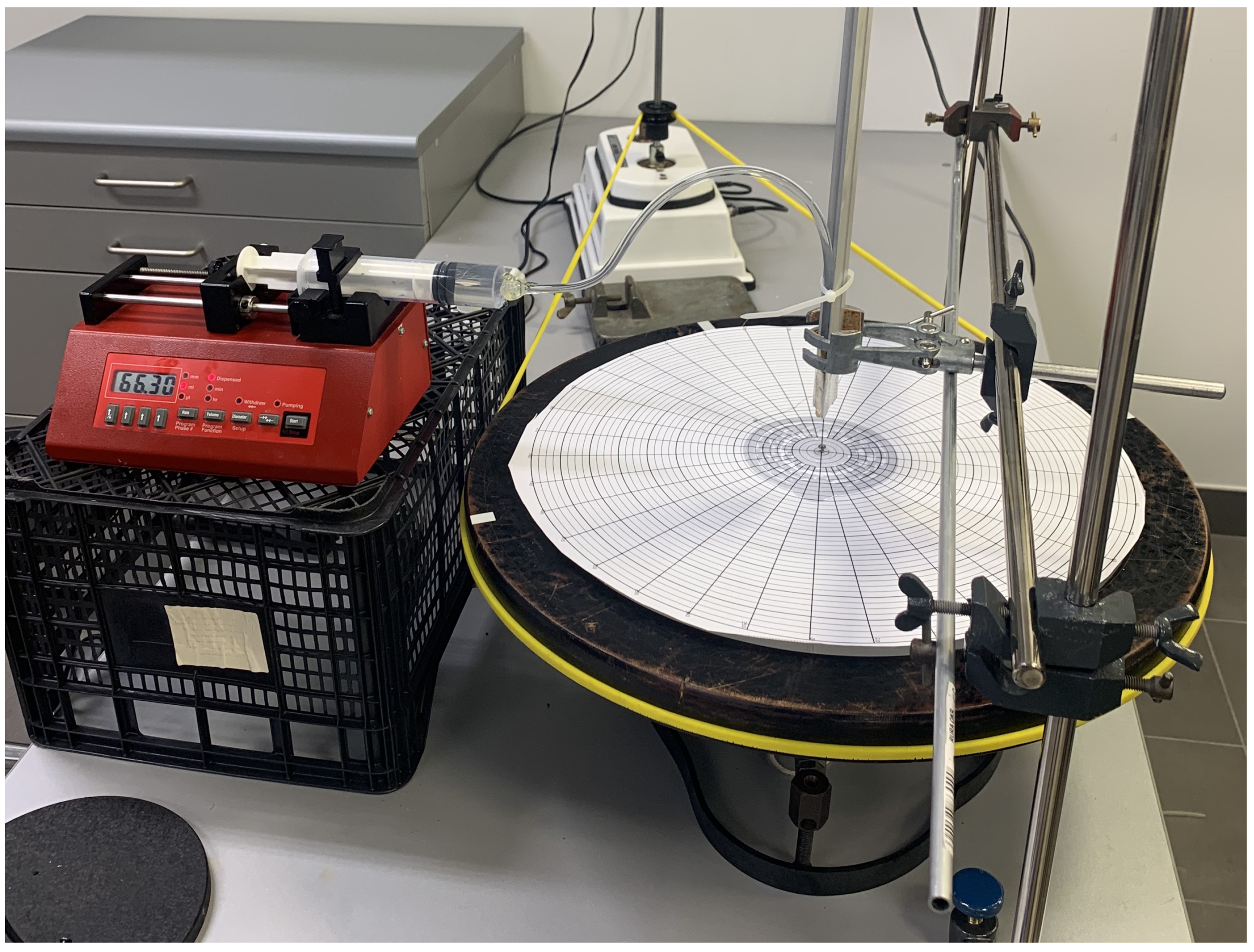
A photo of the experimental apparatus is shown in
Figure 1. The main component is a stainless steel rotating table of diameter 55 cm. A thin (0.5 cm thick) Plexiglas plate of slightly smaller diameter is attached on the top to provide a smooth substrate for paper with circular and radial gridlines, onto which the viscous thread falls. The ruled papers served three functions: they could be quickly changed, obviating the need to scrape and clean the rotating table between experimental runs; they were used to measure the rotational speed of the table from the videos; and they were used to measure radial positions of the recorded traces. For more accurate measurements of the angular speed, a simple tachometer was employed, which clocked the passing of bright markers affixed to the rim of the table. The rotating table was powered by a rubber belt, which was connected to an electric step motor (FPN Warszawa, Poland, model 182, 40 W power). The range of stable angular speeds obtainable with this apparatus was
= 0.09–0.25 Hz. At a given setting of the motor, the system maintained the angular speed with the accuracy of about 5%, as measured using the tachometer. A ruled piece of paper was placed on the rotating table to record the motion of the stream as it fell on the surface. A new sheet was placed on the table after each experimental run.
The flow of viscous fluid was ensured by a syringe equipped with the adjustable automatic dispenser (New Era Instruments NE-1000 syringe pump). The syringe was connected through a tube to a copper nozzle outlet of diameter m and could be moved radially over the table along a metal rail. In all experimental runs, the vertical position of the nozzle and the flow rate were kept constant, with the volume flux Q of either 2 or 3 . The nozzle height above the rotating surface was in the range of H = 4–10 m. During experiments, the distance of the nozzle from the rotation axis, R, was adjusted manually.
Following Morris et al. [
7], silicon oil (manufactured by Tornado) was used as the working liquid. Experiments were conducted at room temperature, which was about 21
C with variations below one degree. Properties of the silicon oil were not measured but were assumed to be those reported by the manufacturer: density
, kinematic viscosity
, and surface tension
.
Since there are six fixed physical parameters
, and three base SI units are needed (kg, m, s), the setup can be characterized by three dimensionless parameters, as guaranteed by the Buckingham
theorem. Following [
7], the three parameters and their approximate values (for
) are given as
The first parameter,
, is smaller but within 9% of the value reported in [
7]. The other two dimensionless parameters differ by a factor of 2.4 and 0.13, respectively, primarily due to the different nozzle diameter
d, which was twice as large in [
7] as here.
In any particular experimental run, while the syringe pump was dispensing liquid at a constant rate, the two variable flow parameters, H and , were kept constant, while the distance to the axis of rotation, R, was varied. In each case, once a constant angular speed was ensured, it was necessary to reach the steady-state behavior of the viscous thread, which required waiting for a few seconds from the moment the stream was released onto the rotating table. It was also necessary to prevent the doubling-up of the viscous thread on itself (i.e., its falling on the trace laid-down earlier) by changing the radius R after each full rotation. The two requirements severely limited useful observation time, particularly for smaller radii R and at faster rotation rates.
In what follows, the four variable parameters are reported in dimensionless forms, defined as
with the characteristic length and angular frequency for our system
Furthermore, there are two ways of introducing the normalizing flow rate
, based on dimensionless
or
. We chose the latter, as we expect that the natural length scale for the flow rate is the diameter of the nozzle
d. Thus, the characteristic flow rate is
and it is based on the length scale independent of
. The approximate corresponding ranges for the experiments reported here were
3. Experimental Results
Experiments were carried out for two flow rates,
and
, four heights,
0.89, 1.11, 1.40, and 1.73, and eight angular speeds,
1.33, 1.43, 1.82, 1.88, 1.92, 2.20, 2.56, and 3.22. It was not possible to set an a priori selected angular speed because the simple electrical motor used did not have a fine speed adjustment or a speed (or voltage) indicator. After setting the speed to the approximate value required, it was measured repeatedly using a tachometer until the system stabilized and twenty consecutive measurements of
differed by the minimal fluctuation obtainable, which also provided a measure of uncertainty; only then did experimental runs commence. This method accounts for a relatively large and variable experimental uncertainty in
, as indicated by the gray vertical strips in
Figure 2 and
Figure 3.
All experimental runs were filmed from above and the videos were used to delineate the transitions between different “stitching” patterns.
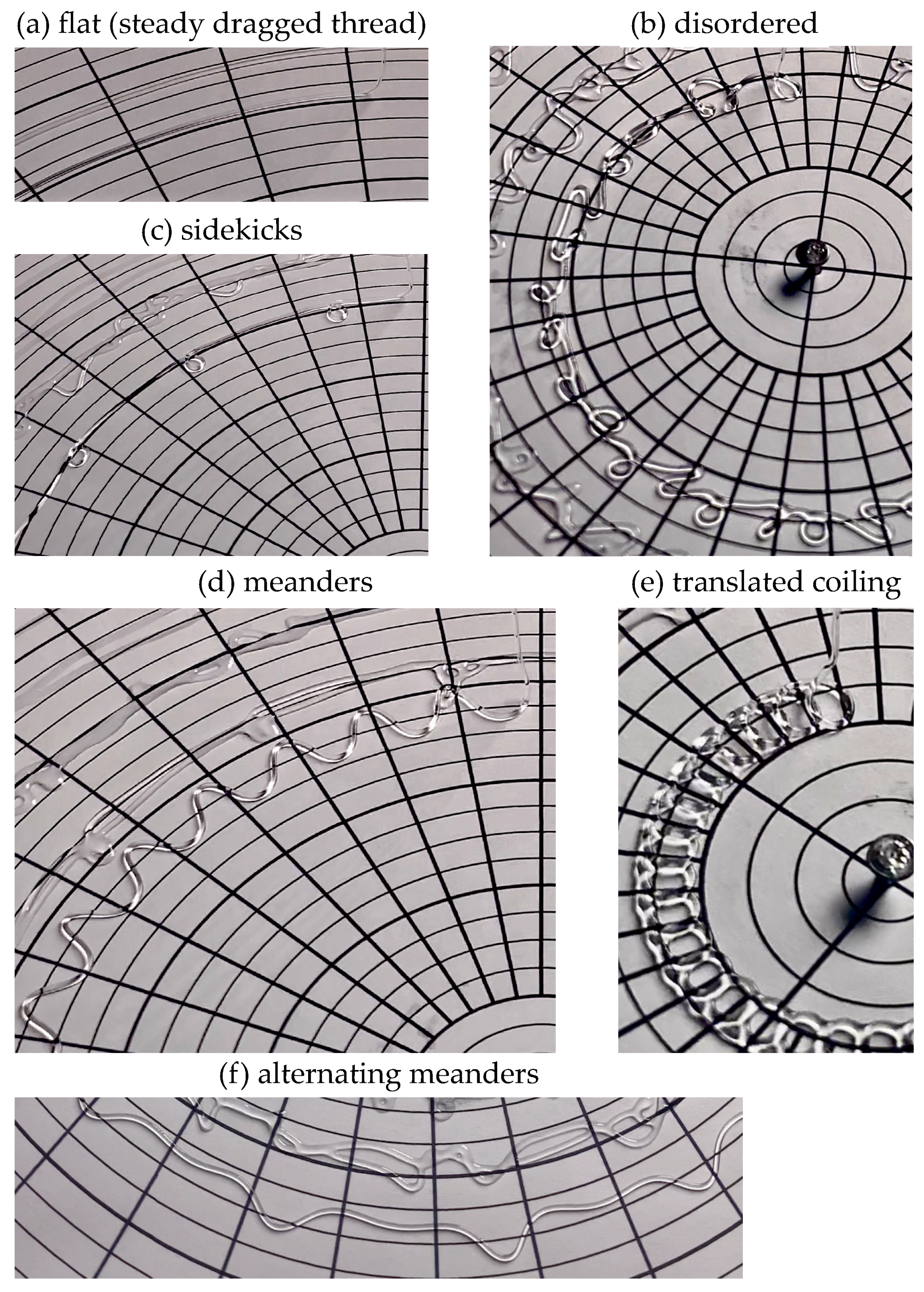
Figure 4, extracted from a film of a single experimental run at
,
, and
R decreasing from approximately 8 to 2 cm, shows a typical sequence of patterns, from the flat trace (no instabilities), to sidekicks, meanders or alternating meanders, and translated coiling.
Disordered patterns, as shown in
Figure 4b, appeared between meanders or alternating meanders and translated coiling. Such chaotic behavior is transitory and occurs between more stable patterns, usually after the system is disturbed, for example, by dragging the thread radially inward or outward. The phase–space plots for this case are shown, for the two values of flow rate
, in
Figure 5.
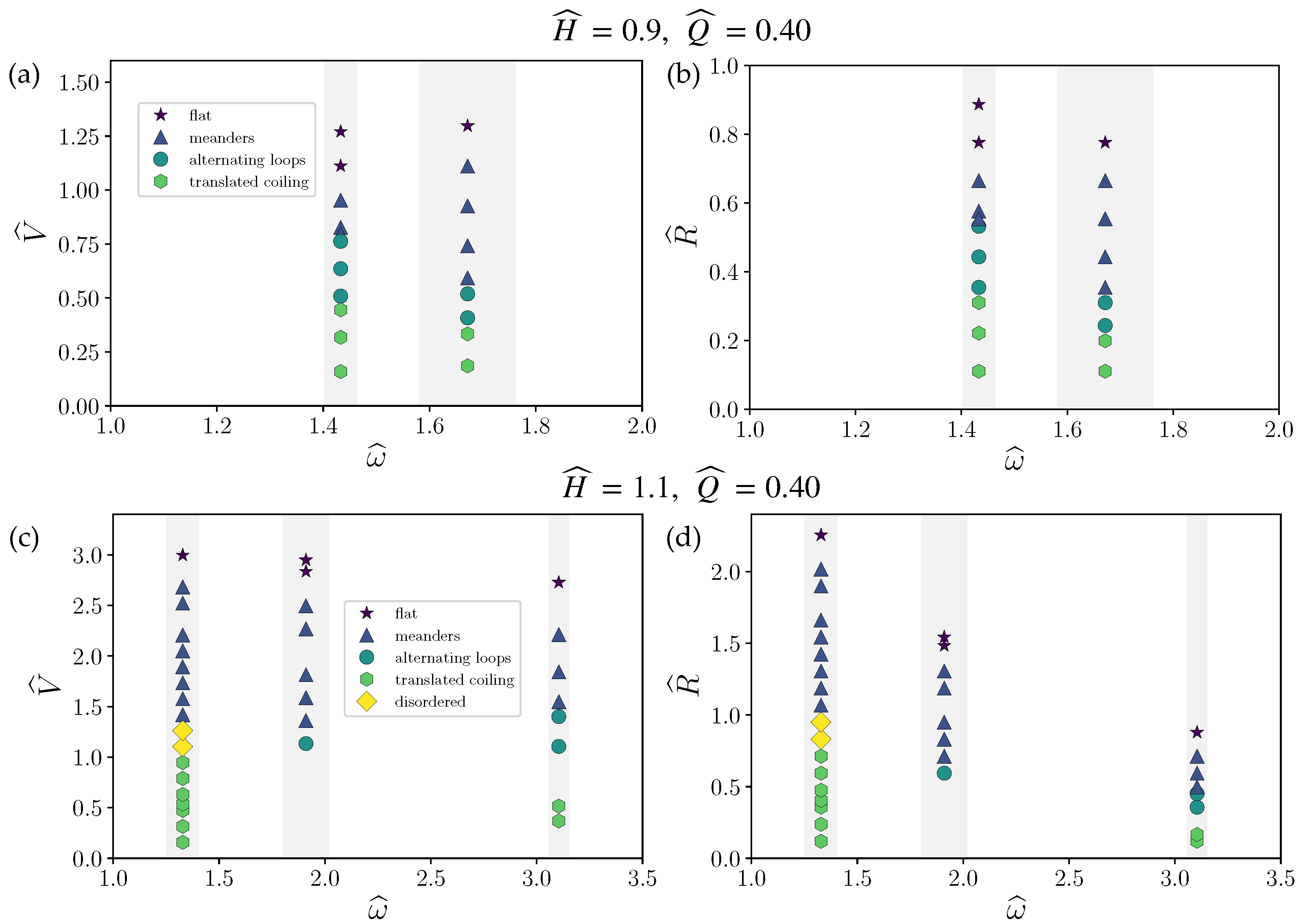
Figure 2 displays results as a function of angular speed for
at two slightly different heights,
and
. At these two smaller heights, a similar sequence of stitching patterns was generated as the radius was decreased, transitioning from flat trace to meanders, alternating loops, and translated coiling. Distinct sidekicks were not observed, while sustained chaotic patterns appeared only at the larger height and lower rotational rates, consistent with the trends encapsulated in
Figure 5.
Some of the data corresponding to translated coiling in
Figure 2, for
,
, and
, are illustrated in the photographs of
Figure 6. Panel (a) shows the traces created at
cm (
); panel (b) at
cm (
); and panel (c) at
cm (
). A striking feature of this sequence is the reversal of the direction of coiling from panel (b) to panel (c), and the corresponding shift from outward (radially away from the axis) to inward (radially toward the axis) loops. Whether this transition was forced by the circular geometry itself, the impact of pulling the stream radially out, or a combination of the two effects remains to be investigated. The falling stream is certainly prone to disturbances which are amplified and determine the transient patterns until fluctuations are damped and a stable pattern emerges.
Behavior at the larger of two flow rates,
and
, is summarized in
Figure 3. Only two sustained stitching patterns, meanders and translated coiling, were observed in this case; double meanders, sidekicks, and alternating loops were not observed. It is possible that even at this larger height, as compared to
and
in the experiments of
Figure 2, the larger flow rate damped-out these particular stitching patterns.
4. Comparison with FMSM
The phase diagrams of
Figure 2 and
Figure 3 indicate that the clearly observed patterns, while fewer in number, generally followed a similar order for decreasing
, as in classical (linear) FMSM [
1,
7,
10,
13], with meanders, sidekicks, and translated coils as the most common forms. The “missing” forms, such as slanted loops, two-by-two, bunched double coiling, bunched meanders, braiding, and W pattern (in the terminology of Chiu-Webster and Lister [
1]) were not reliably captured in the experimental runs reported here. Conceivably, these forms might have been missed or suppressed within the limited parameter space explored.
Several stitching patterns were observed only briefly, after the experimental conditions were adjusted and the system was transitioning towards a new pattern. This happened in particular when the radius was changed while other parameters were kept constant. Indeed, the stitching patterns were extremely sensitive to the initial conditions and also subject to hysteresis. A significant limitation of the apparatus was the absence of an oil scraping mechanism. This meant that reliable observations for any given conditions could only be carried out over one full rotation of the table. For larger angular speeds, and smaller radii, this constituted a severe constraint and is probably the reason why some “classical” patterns were not seen.
Quantitative comparisons with the classical FMSM can be only approximate since the experiments reported here did not reproduce the exact conditions of the earlier investigations. The principal difference lies in the initial diameter of the stream, which was
mm in the present investigation and
mm in [
7]. The initial speeds of the stream exiting the nozzle were also different, approximately 0.3
(or 0.4
for the larger flow rate) in the rotating system and 0.05
in the linear case, respectively. Finally, flow rates in dimensional terms differed by about 20% (30%).
However, a rough comparison of the thresholds between different stitching patterns can be attempted, relying on the transition from the flat trace to meanders, the most robust indicator. Choosing
Figure 2c, wherein highly consistent data for three different values of angular speed are provided at a smaller value of
Q, at
cm, this first transition occurred at the local translational speed of the turntable
. For the same height, Figure 4 in [
13] (adopted from Figure 3 in [
7]) indicates the belt speed of
. We conjecture that at smaller flow rates and doubled diameter of the oil dispensing nozzle, the stream in [
7] must have been much thinner at contact with the surface than in our experiments. For a conclusive comparison, the same fluid dispensing mechanism should ideally be used in both linear and rotational experiments.
In the regular, translational FMSM apparatus, the circulation of the viscous thread, as in the Magnus effect, breaks the transverse symmetry of the flow. This raises the question of the additional breaking of symmetry due to the local centripetal acceleration of the rotating surface. There are, conceivably, three separate classes of symmetry-breaking manifestations. The first would be a deformation of the shapes of the arcs with respect to the “classical” FMSM traces; the second, additional breaking of the symmetry with respect to the center line of the trace; the third, evidence that either outward or inward arcs or loops become more likely.
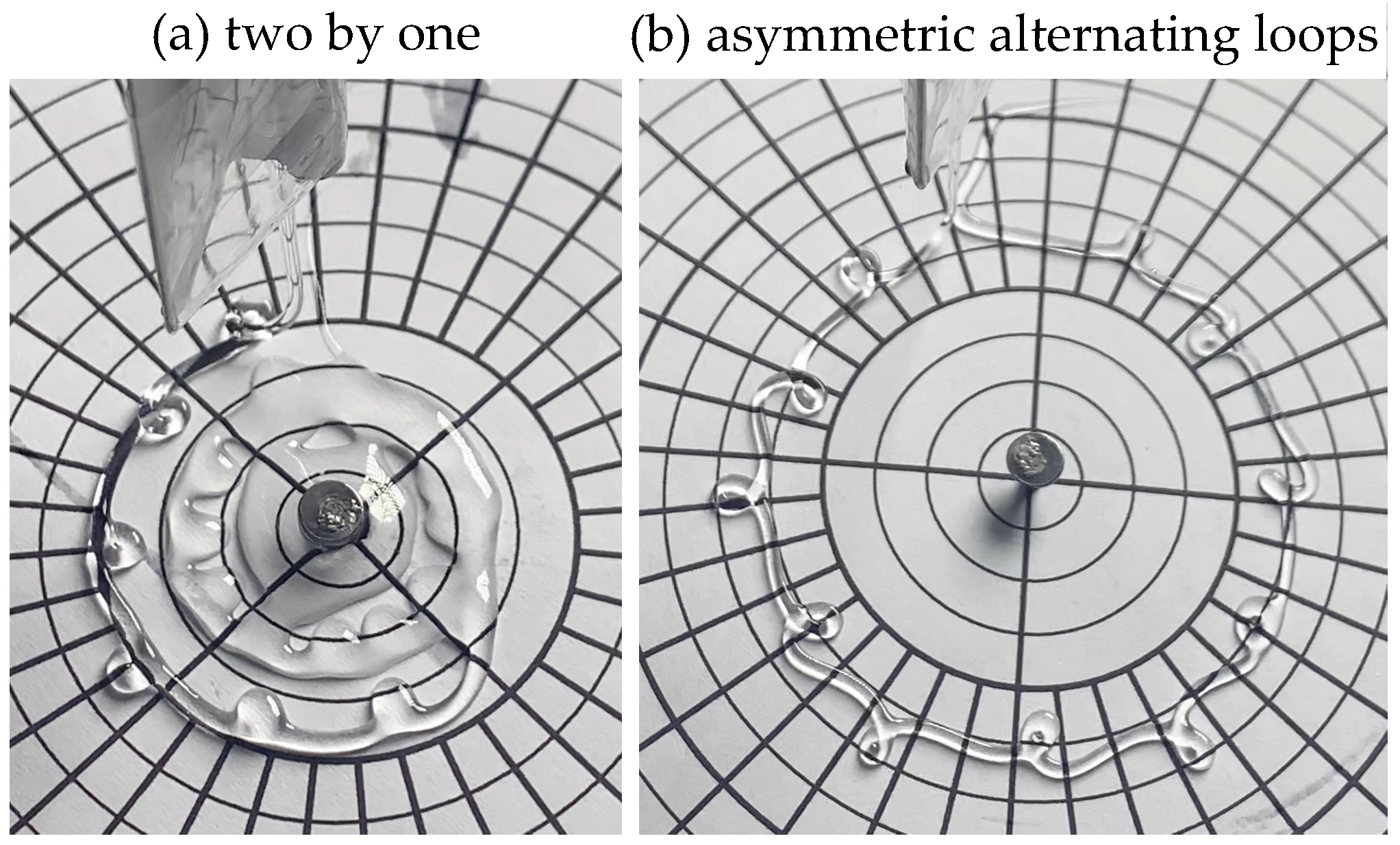
For the range of parameters accessible with the present apparatus, the effect of circular geometry on the form of the traces, and their transverse (inward–outward) asymmetry, was subtle and, in most cases, difficult to discern. All the same, some of the transitory patterns observed have apparently not been seen before. The two most conspicuous novel forms are shown in
Figure 7. The first, in panel (a), is a pattern with pairs of inward loops separated by an outward loop, which we call two-by-one in analogy to the two-by-two pattern seen earlier (Figure 3 in [
13]). Whether a two-by-one pattern can be obtained in a translational FMSM remains to be verified. The second, which we call asymmetric alternating loops, corresponds to the alternating loops seen before, but with an evident symmetry-breaking feature. Here, the S-shaped links connecting subsequent loops display a pronounced centrifugal bulge in the outward-pointing arcs preceding inward loops.
It remains uncertain whether in the rotating system outward pointing loops are more likely to occur than inward facing ones (or vice versa). Some of the recorded runs, such as the one illustrated in
Figure 6, appear to indicate a tendency to form outward coils at smaller radii, when centrifugal effects at a given
V would be expected to be the strongest. Further systematic experiments will be needed to elucidate these effects, if they are indeed present.
5. Concluding Remarks
The present study is a preliminary experimental exploration of a rotational version of the fluid-mechanical sewing machine. Although limited in scope, it is the first investigation of a viscous thread falling on a locally accelerating surface. The photographs of the traces shown in
Figure 4,
Figure 6 and
Figure 7, taken by a fixed camera above the turntable, therefore depict a non-inertial reference frame.
As in previous FMSM studies, a single working liquid was used, silicon oil, and the diameter of the nozzle d was kept the same in all experiments, while the flow rate Q was limited to two values. The remaining flow parameters, , R, and H, were varied over a small range of discrete values. However, even within this limited dataset, a number of new results can be extracted.
Since the observational time was limited to one period of revolution () for any fixed radius R in any given experimental run, some of the stitching patterns documented in earlier experiments were missed. Nevertheless, the sequence of patterns observed at decreasing qualitatively followed the usual order for translational FMSM: flat line, meanders, alternating loops (when present), and translated coiling.
The rotational effects in the form of the stitching patterns proved, in general, subtle. Symmetry-breaking features, such as differences in morphology relative to the equivalent traces in FMSM, for example, local curvature, are estimated to be below 10% in most cases. One notable exception was an asymmetric variant of the alternating loop pattern observed at
,
,
, and
,
Figure 7b, wherein centrifugal deformations are clearly discernible—the arcs connecting loops directed away from the axis are more pronounced than those toward the axis, while the outward loops are more elongated than the inward loops. Again, additional experiments will be needed to elucidate this new form and search for other symmetry-breaking features, expected to be more evident at larger values of
R and
, and for a given
V, at decreasing
R.
The distinction between inward and outward loops is enabled by the circular geometry of the setup. Similar distinction arises when a solid, elastic rope falls on a rotating platform and undergoes buckling instability. Amnuanpol explored this scenario [
16] and found two new modes of coiling: circles with outward loops (hypotrochoids) and circles with inward loops (epitrochoids). The former dominate for large fall height, feeding speed, and angular speed, whereas the latter is transitional between outward loops and circles. A similar transition for a liquid rope is documented in
Figure 6, but we do not have sufficient data to ascertain whether the two phenomena are close analogues.
Detailed quantitative comparisons with the “classical” FMSM will require additional systematic experiments, with three dimensionless parameters delineating the dynamics,
,
, and
, matching those in [
7] more closely, and also a similar mechanism for dispensing the liquid. Adding a scraping mechanism would allow much longer observation times under any given conditions so that the system could reliably reach steady-state equilibrium. This would be particularly useful at large heights,
H, when the thread is very thin and thus extremely susceptible to external perturbations.
We conclude by noting that a painting technique based on the scenario described here could perhaps open new artistic opportunities within the abstract idiom. Imagine a few paint dispensers suspended and movable over a spinning circular canvas. By carefully varying their radial positions, an intricate network of meandering and looping skeins could be obtained. A subtle interplay of symmetric and asymmetric patterns would then naturally emerge.


