Abstract
The movement of a wheelchair with manual propulsion depends on the kinematics of the human body and the forces exerted by the muscles. To design innovative wheelchair propulsion systems, the biomechanical parameters resulting from human interaction in this anthropotechnical system must be formalised. The research objectives were thus adopted: an analysis of the propulsion wheel angle of rotation resulting from the hand movement’s trajectory and the mathematical formalisation of the propulsion wheel angle of rotation described as a function of the propelling phase’s duration. The research was carried out using three variants of manually propelled wheelchairs on a group of 10 patients representing the same group (C50) of anthropometric dimensions. The research demonstrated that the function of the propulsion wheel angle of rotation shows the features of central symmetry occurring at an angle of rotation of φ 52° and a propelling phase duration of 58%. Moreover, the measurements were averaged and a mathematical model of the propulsion wheel rotation function during the propulsion phase was developed, depending on the percentage of duration.
1. Introduction
The way in which the function of motion is performed depends on the type of wheelchair being used [1,2,3]. The basic classification of wheelchairs defines them as electric, manual, or hybrid wheelchairs [4,5]. Manual propulsion wheelchairs are the most common and widespread type of wheelchair. They gained popularity thanks to their simple design and high mobility. The disadvantage of this type of solution is that the motion entirely depends on the strength of the user’s muscles [6,7] and the kinematics of their body. Therefore, the use of such propulsion is closely related to human kinematics [8] and muscular effort [9].
The process of propelling a manual wheelchair consists of two phases: the propelling phase and the return phase. This division results from observations of the path of the hand movement [10,11,12] and the two distinct parts, in which the hand holds the handrims and then freely returns to the starting position. The propelling phase is when the hand holds the handrims and the muscular system generates the propelling force [13,14] that is delivered to the propulsion wheel. The return phase is when the hand returns freely to the starting position. During this phase, the movement of the upper limb is not restrained, and the way the user returns to the starting position translates only into the duration of the entire propelling cycle, which is a combination of the propelling and return phases.
When linking the movement of the upper limb with the kinematics of the wheelchair as an anthropotechnical system, it was found that the propelling phase is the most important one, since the propelling force is delivered to the system during this phase. However, as shown by a number of publications, the intensity of the propelling force generated varies [15]. The variability of this force results from the variability of the angular acceleration [16] of the propulsion wheel pushed by the user’s upper limb. This variability of wheelchair acceleration can be observed by measuring the wheelchair’s wheel angle of rotation [17]. Assuming that the hand is holding the handrim during the propelling phase, it is possible to analyse the acceleration of the wheelchair in the propelling phase based on the measurement of the hand motion capture [18,19]. Such measurement takes into account the hand slipping in relation to the handrims, which is normally ignored by researchers. Hand slipping occurs most often when grasping and letting go of the handrims.
Knowing that the path of hand movement in the propelling phase is defined by the shape of the propulsion wheel and the position of the trunk in relation to its axis of rotation, two research objectives were adopted. The first one is an analysis of the propulsion wheel angle of rotation resulting from the trajectory of the hand’s movement during the propelling phase; the second one is the mathematical formalisation of the propulsion wheel angle of rotation described as a function of the propelling phase duration. These research objectives are justified by the ongoing work on modifications and improvements to wheelchair manual propulsion systems [5,20,21,22]. When developing such innovative manual propulsion systems, it is necessary to provide data reflecting the so-called human factor, in this particular case, referring to the course of the angle of rotation of the propulsion wheel during the propelling phase.
2. Materials and Methods
2.1. Measuring Apparatus
The propulsion wheel angle of rotation during the propelling phase was measured using a measuring system attached to each of the wheelchairs used in the tests (Figure 1). The system consisted of a GoPro HERO 7 camera (a) and a lamp (b) mounted on a boom (c) permanently fixed to the frame of the wheelchair. The camera records the image in 960p resolution with a speed of 240 fps. The image was saved in .mp4 format. Fragments in which the upper limb made a driving movement were manually extracted from the recorded image. Bandicut software was used to split the raw material. Using proprietary software, a calibration file was generated for the camera used. This file defined the parameters of image bending through the camera lens. The calibration file eliminated the “fisheye” effect and made it possible to generate a scale between the actual dimension of the AruCo marker and its size on the image recording. The illuminating lamp provides a lighting intensity of 200 to 1000 lm. The camera recorded AruCo markers (d) 50 mm by 50 mm [23]. Proprietary software based on the OpenCV library was used to analyze the recorded image with Aruco markers. This software made it possible to detect the position of the movable markers in relation to the stationary ID0 marker. Kulyukin described a similar effect of object detection on selected frames from the recording in his publication [24].
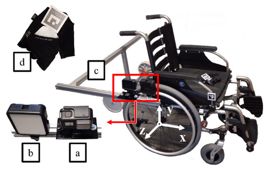
Figure 1.
Measuring apparatus used in the research: (a) GoPro HERO 7 camera, (b) lamp, (c) boom, (d) AruCo marker.
2.2. Patients and Wheelchairs
Ten patients took part in the research (Table 1), classified according to height, weight, age, maximum push force of the upper limb, and wheelchair experience. The push force measuring method was methodologically formalised and used a special station where the user, in a sitting position, pushed the handle connected with the strain gauge towards the knee. The patients subjectively evaluated the experience using a five-point scale. Each patient was acquainted with the research procedure and provided informed consent to participate in the study. Prior to commencing the research, it was decided to include people with unimpaired mobility due to the use of prototype propulsion system solutions in difficult field conditions. The study was accepted by the Bioethical Commission at Karol Marcinkowski Medical University in Poznań, Poland (Resolution No. 1100/16 of 10 November 2016, under the guidance of Prof. MD P. Chęciński for the research team led by B. Wieczorek, PhD). The authors obtained the written consent of the individuals involved for the publication of research results. The data were presented in such a way as to ensure complete anonymity.

Table 1.
Comparison of anthropometric features and the level of experience in operating a wheelchair for the test subjects.
The research tests were performed using three wheelchairs equipped with manual handrim propulsion: Vermeiren v300 (W1), ARmedical AR-300 (W2), and the Vermeiren v300 equipped with an anti-rollback system (W3) [PL 239693].
2.3. Measurement Test
The kinematics analysis was limited to the hand movement analysis (ID1) (Figure 2a). The measurement test required the patient to ride through a route consisting of four sections (Figure 2b): a horizontal section allowing for the acceleration of the wheelchair (Section A), a ramp section inclined at an angle of α = 4.58° (Sections B and C) and a horizontal section allowing for braking of the wheelchair (Section D). Full propulsion motions made on the final inclined section (Section C) were selected for the analysis. In this way, the influence of the mechanical energy [25] accumulated during the wheelchair acceleration in the form of inertia of the accelerated system (section A) was minimised. Each patient performed three measurement tests on each of the three wheelchairs, based on which three propelling cycles were selected. Subsequently, the selected propelling cycles were averaged and represented each patient.
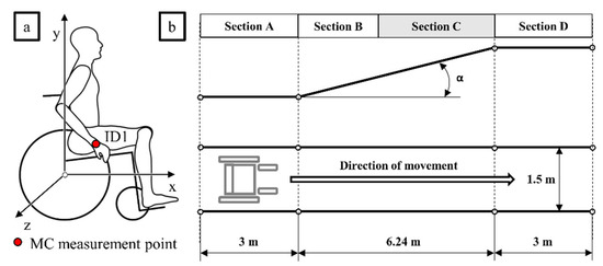
Figure 2.
Schematic layout of the motion capture measuring point (a) and the ramp on which the tests were carried out (b), where Section A—part of the route where the wheelchair was accelerated, Section B—section of the route for which the measurement results were not taken into account, Section C—section of the route for which the measurement was performed, Section D—the final section where the wheelchair was stopped, α—the inclination angle of the route.
The measurement of the propulsion wheel angle of rotation during the propelling phase was determined by the hand trajectory during the propelling cycle (Figure 3). Knowing the trajectory of the hand, the angular position of the hand in relation to the vertical axis β (1, 2) and the total angle of rotation of the propulsion wheel φ (3) as a function of the percentage of the propelling phase’s duration (PD) were determined.
where gSx is the position on the horizontal axis of point gS, gSy is the position on the vertical axis of point gS, gEx is the position on the horizontal axis of point gE, gEy is the position on the vertical axis of point gE, n is any positive real number, x is the position of the trajectory point along the horizontal axis, y is the position of the trajectory point on the vertical axis and PD is the percentage of the propelling phase’s duration.
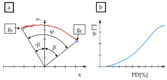
Figure 3.
An example graph of the hand movement’s trajectory (a) and the total angle of rotation of the propulsion wheel as a function of the duration of the propulsion cycle in per cent (b), where gS.—handrim grasping point, gE—handrim releasing point, β—angular position of the hand in relation to the vertical axis, φ—propelling wheel angle of rotation, PD—percentage of the propelling phase’s duration.
2.4. Measurement Evaluation
On the basis of the measurement and processing of the measurement signal, in accordance with the method described above, the change of the handrim’s angle of rotation as a function of the percentage of the propelling phase’s duration was assessed (Figure 4). The dependence of the propulsion wheel angle of rotation on the percentage of the propulsion phase was utilised to unify the measurement results for all patients. The unification was necessary because each patient executed the propelling phase at different times. The procedure for converting the propelling phase duration (expressed in seconds) into the percentage of the propelling phase’s duration was formalised with Equation (4):
where ti is any time from the interval <0; tmax>, tmax is the propelling phase’s duration, and PD is the percentage of the propelling phase’s duration.
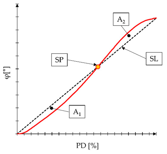
Figure 4.
Graph of the handrim’s rotation angle course (the parameters used to evaluate the symmetry are marked). SP—central symmetry point, SL—symmetry line, A1—area of the area delineated by the lines of symmetry and the line of the rotation angle function of the circle to the left of the symmetry point, A2—the area of the field plotted by the lines of symmetry and the line of the wheel angle of rotation to the right of the midpoint, φ—angle of rotation of the drive wheel, PD—duration of the driving phase expressed as a percentage.
Central symmetry in the course of the propulsion wheel angle of rotation was observed from the test results and the review of the measuring signal. In order to analyse this phenomenon, two parameters—describing the point of central symmetry (SP) and the lines of symmetry (SL)—were determined. SP was defined by two coordinates (5), whereas SL was the trend line for the analysed real course of the angle of rotation φ.
where φ is the propulsion wheel angle of rotation recorded after the end of the propulsion phase and PD is the percentage of the propulsion phase’s duration, ranging from 0–100%.
Bearing in mind that the test was performed on humans, it was not possible to obtain a perfectly central symmetry. Therefore, in further analysis, the symmetry coefficient SF (6) was determined, describing by what per cent a given result differed from the ideal symmetry. When the SF coefficient reaches the value of 0, there is perfect central symmetry [26]; positive values indicate right asymmetry, and negative values indicate left asymmetry. This asymmetry should be understood as the direction of the shift in the symmetry point SP.
where A1 is the area of the field delineated by the lines of symmetry and the line of the wheel angle of rotation to the left of the symmetry point, and A2 is the area of the field delineated by the lines of symmetry and the line of the wheel angle of rotation to the right of the symmetry point.
3. Results and Discussion
In accordance with the study methodology, the average course of the change in the propulsion wheel angle of rotation as a function of the percentage of the propulsion phase’s duration was determined for each patient (Figure 5). Additionally, a comparison of the mean of the function of the propulsion wheel angle of rotation φ depending on the wheelchair was carried out for all patients (Figure 5d).
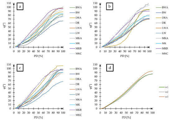
Figure 5.
Graph of the function of changing of the propulsion wheel angle of rotation depending on the percentage of the propulsion phase’s duration: (a) wheelchair W1, (b) wheelchair W2, (c) wheelchair W3, and (d) averaged φ function of all patients for individual wheelchairs.
Based on the courses of the propulsion wheel angle of rotation, it was found that for each patient, there was central symmetry in the shape of the function φ. Despite variance in the final values of the propulsion wheel angle of rotation, two characteristic inflections of the function were noticeable for each patient, the first of which occurred in the range of 0–50% PD, and the second was in the range of 50–100% PD. By averaging the patient results for individual wheelchairs (Figure 5d), it was found that the model of the wheelchair did not affect the course of the propulsion wheel angle of rotation.
The differences in the values of the propulsion wheel angle of rotation φ obtained by individual patients result from their physical attributes, such as the strength and length of the upper limbs (hand, forearm, arm). Therefore, in further analysis, the results of all patients for individual wheelchairs were averaged. This procedure is justified because it was earlier found that the function of the propulsion wheel angle of rotation φ for each patient had the same characteristics as the inflection points and that each function had the same PD time base.
Using the averaged functions of changing the propulsion wheel angle of rotation, graphs were prepared for each wheelchair, enabling an analysis of the symmetry (Figure 6, Figure 7 and Figure 8). Additionally, using the averaged results for the three wheelchair models, an additional graph was prepared that represented the entire group of wheelchairs equipped with manual handrim propulsion (Figure 9). In addition to the averaged function of the propulsion wheel angle of rotation AVG φ, the course of the approximate function by the mathematical model MOD, the symmetry line SL, the central symmetry point SP and the value of the standard deviation between the patients σ φ are marked on these graphs. The numerical values describing the symmetry parameters are included in Table 2.
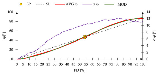
Figure 6.
A graph of the averaged function of the change of the propulsion wheel angle of rotation and the standard deviation depending on the duration of the propulsion phase for wheelchair W1. SP—symmetry point, SL—symmetry line, AVG φ—mean for all patients’ function of the propulsion wheel angle of rotation, σ φ—standard deviation between the participants, MOD—mathematical approximation function of the average function AVG φ, φ—propulsion wheel angle of rotation, PD—the percentage of the propelling phase’s duration.
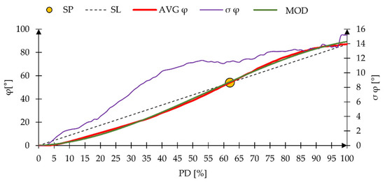
Figure 7.
A graph of the averaged function of the change of the propulsion wheel angle of rotation and the standard deviation depending on the duration of the propulsion phase for wheelchair W2. SP—symmetry point, SL—symmetry line, AVG φ—mean for all patients’ function of the propulsion wheel angle of rotation, σ φ—standard deviation between the participants, MOD—mathematical approximation function of the average function AVG φ, φ—propulsion wheel angle of rotation, PD—the percentage of the propelling phase’s duration.
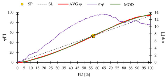
Figure 8.
A graph of the averaged function of the change of the propulsion wheel angle of rotation and the standard deviation depending on the duration of the propulsion phase for wheelchair W3. SP—symmetry point, SL—symmetry line, AVG φ—mean for all patients’ function of the propulsion wheel angle of rotation, σ φ—standard deviation between the participants, MOD—mathematical approximation function of the average function AVG φ, φ—propulsion wheel angle of rotation, PD—the percentage of the propelling phase’s duration.
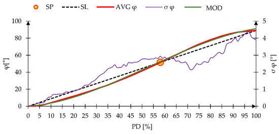
Figure 9.
A graph of the averaged function of the change of the propulsion wheel angle of rotation and the standard deviation depending on the duration of the propelling phase for the entire group of the manual handrim propulsion wheelchairs and for all patients. SP—symmetry point, SL—symmetry line, AVG φ—mean for all wheelchairs’ function of the propulsion wheel angle of rotation, σ φ—standard deviation between the tested wheelchairs, MOD—mathematical approximation function of the average function AVG φ, φ—propulsion wheel angle of rotation, PD—the percentage of the propelling phase’s duration.

Table 2.
List of parameters describing the central symmetry of the average function of the propulsion wheel angle of rotation for wheelchairs W1, W2, and W3 and for the entire group equipped with a manual handrim propulsion system (AVG W). PD—propelling phase duration, φ—handrim rotation angle, SF—symmetry coefficient, t—propelling phase duration.
Based on the analysis of the average function of the propulsion wheel angle of rotation AVG φ for individual wheelchairs, a significant similarity was found in the course of these functions. This is confirmed by the mathematical models for approximating AVG functions φ. The resulting polynomials (7–9) for individual wheelchairs are characterised by similar values of the polynomial coefficients, which is a sufficient premise for excluding the influence of the wheelchair model on the course of the handrim’s rotation angle function.
where φW1 is a polynomial approximating the propulsion wheel angle of rotation changing function course, depending on the percentage duration of the propelling phase for wheelchair W1, φW2 is a polynomial approximating the propulsion wheel angle of rotation changing function course, depending on the percentage duration of the propelling phase for wheelchair W2, φW3 is a polynomial approximating the propulsion wheel angle of rotation changing function course, depending on the percentage duration of the propelling phase for wheelchair W3 and PD is the percentage of the propulsion phase’s duration.
When analyzing the standard deviation σ φ, it was noticed, regardless of the wheelchair model, the differentiation in the value of the angle of rotation of the drive wheel generated by patients increases with the duration of the PD drive phase. The maximum values of the standard deviation were 12° for wheelchair W1, 15° for wheelchair W2, and 14° for wheelchair W3. The differences between patients resulted from different body structures (despite the same percentile of anthropometric dimensions being considered), physical strength, and wheelchair propelling style. The greatest discrepancies between patients were found around the central point of symmetry SP. The discrepancy in the value of the propulsion wheel angle of rotation near SP should be explained by the differences in the anthropometric dimensions of the participants. By watching the patients during the test, it was found that the position of SP during the propelling phase occurred when the hand was at the highest point on the handrim of the propelling wheel, i.e., at an angle β = 0° (Figure 3), whereas the duration of the propelling phase for which this phenomenon occurred resulted from the speed of the hand and the length of the entire limb.
An important observation is the location of the symmetry point SP, which is significant for systems characterised by central symmetry. For all wheelchairs, this point was located near the centre of the propulsion phase PD duration and in the half of the maximum propulsion wheel angle of rotation φ. The position of SP for all wheelchairs was on the horizontal axis within the range of 54–62% and on the vertical axis within the range of 47°–54°. Based on these results, one can see a tendency for SP to shift to the right and up relative to the midpoints. The reason for this is the position of the propulsion wheel axis of rotation in relation to the seat. However, exploring the factors affecting this relationship would require a separate study.
The analysis of symmetry using the symmetry factor SF did not reveal perfect symmetry in any case. The expected result is due to the participation of different patients and the human factor related to the individual capabilities of each patient. However, the asymmetry was small, ranging from 3% to 14%, which is a good result by the standards of an anthropotechnical system burdened with very small repeatability of measurement attempts.
Bearing in mind the above observations and the lack of contraindications to averaging the results for the three tested wheelchairs as one object representing the entire group of semi-active manual wheelchairs with manual handrim propulsion, a generalised mathematical model was derived that can determine the current propulsion wheel angle of rotation φ(PD), depending on the percentage of the PD propelling phase’s duration (10).
Describing the model in absolute form, expressed as a percentage of the propelling phase’s duration, allows it to be adapted to different patients with different paces of wheelchair propelling. This model, assuming the total duration of the propelling phase expressed in seconds, can generate the course of the function of the propelling wheel angle of rotation, depending on the actual duration of the propelling phase.
4. Conclusions
The tests performed for this study showed central symmetry in the shape of the propulsion wheel angle of rotation changing function during the propelling phase. This observation made it possible to discover the influence of both the physical features of the wheelchair and the human anthropometric features on the difference in the rate of handrim propulsion. The symmetry found in the results made it possible to distinguish three stages of the propelling phase, characterised by different hand movement accelerations. The first stage lasted from 0 to 45% of the propelling phase of the wheel acceleration, the second stage lasted from 45 to 70% of the propelling phase—in which the hand moved with constant acceleration—and the third stage lasted from 70 to 100% of the propulsion phase, in which the hand pushing the handrim decelerated.
The research has shown that the average position of the central symmetry occurred for the rotation angle φ of 52° and that the propelling phase duration amounted to 58%. In further research, it should be checked how the position of this point is influenced by the position of the seat in relation to the propulsion wheel axis of rotation. Based on the tests carried out during the research, it can be concluded that the horizontal position of the central symmetry point had the greatest impact on the position of the seat in relation to the propulsion wheel axis of rotation.
The convergence of the results obtained for individual patients and wheelchairs made it possible to derive a mathematical model of the propulsion wheel angle of rotation function during the propulsion phase. The model was obtained on the basis of 90 individual measurement tests (10 patients performing three measurement tests on three wheelchairs of the same type) and can be successfully used in the further description of wheelchair kinematics. Moreover, it can be used in the design of innovative wheelchair propulsion systems, the purpose of which will be to unify the speed of the propelling system.
5. Patents
Patent in the Patent Office of the Republic of Poland, PL 239693, Module for the Universal Lever Brake of a Wheelchair Wheel, WIECZOREK Bartosz, WARGUŁA Łukasz, KUKLA Mateusz, 2019.
Funding
This research is a part of the project: “Innovative Drive Systems for Wheelchairs—Design, Prototype, Research, number: “Rzeczy są dla ludzi/0004/2020”, financed by the National Centre for Research and Development, https://www.gov.pl/web/ncbr (accessed on 3 October 2021).
Institutional Review Board Statement
The study was accepted by the Bioethical Commission at Karol 97 Marcinkowski Medical University in Poznań, Poland (Resolution No. 1100/16 of 10 No-98 vember 2016, under the guidance of P. Chęciński for the research team led by B. 99 Wieczorek PhD).
Informed Consent Statement
Informed consent was obtained from all subjects involved in the study.
Data Availability Statement
Not applicable.
Conflicts of Interest
The authors declare no conflict of interest.
References
- Shore, S. Use of an economical wheelchair in India and Peru: Impact on health and function. Med. Sci. Monit. 2008, 14, PH71–PH79. [Google Scholar] [PubMed]
- Rispin, K.L.; Hamm, E.; Wee, J. Discriminatory validity of the Aspects of Wheelchair Mobility Test as demonstrated by a comparison of four wheelchair types designed for use in low-resource areas. Afr. J. Disabil. 2017, 6, 11. [Google Scholar] [CrossRef] [PubMed][Green Version]
- Fitzgerald, S.G.; Cooper, R.A.; Boninger, M.L.; Rentschler, A.J. Comparison of fatigue life for 3 types of manual wheelchairs. Arch. Phys. Med. Rehabil. 2001, 82, 1484–1488. [Google Scholar] [CrossRef] [PubMed]
- Lawn, M.; Takeda, T. Design of a robotic-hybrid wheelchair for operation in barrier pre-sent environments. In Proceedings of the 20th Annual International Conference of the IEEE Engineering in Medicine and Biology Society, Hong Kong, China, 1 November 1998; Volume 20 Biomedical Engineering Towards the Year 2000 and Beyond (Cat. No. 98CH36286). IEEE: Piscataway, NJ, USA, 1998; Volume 5, pp. 2678–2681. [Google Scholar]
- Wieczorek, B.; Warguła, Ł.; Rybarczyk, D. Impact of a Hybrid Assisted Wheelchair Propulsion System on Motion Kinematics during Climbing up a Slope. Appl. Sci. 2020, 10, 1025. [Google Scholar] [CrossRef]
- Lieber, R.L.; Friden, J. Muscle damage is not a function of muscle force but active muscle strain. J. Appl. Physiol. 1993, 74, 520–526. [Google Scholar] [CrossRef]
- Reilly, D.T.; Martens, M. Experimental Analysis of the Quadriceps Muscle Force and Patello-Femoral Joint Reaction Force for Various Activities. Acta Orthop. Scand. 1972, 43, 126–137. [Google Scholar] [CrossRef]
- Galli, G.; Noel, J.-P.; Ecanzoneri, E.; Eblanke, O.; Eserino, A. The wheelchair as a full-body tool extending the peripersonal space. Front. Psychol. 2015, 6, 639. [Google Scholar] [CrossRef]
- Glaser, R.M.; Sawka, M.N.; Brune, M.F.; Wilde, S.W. Physiological responses to maximal effort wheelchair and arm crank ergometry. J. Appl. Physiol. 1980, 48, 1060–1064. [Google Scholar] [CrossRef]
- Boninger, M.L.; Souza, A.L.; Cooper, R.A.; Fitzgerald, S.G.; Koontz, A.M.; Fay, B.T. Propulsion pat-terns and pushrim biomechanics in manual wheelchair propulsion. Arch. Phys. Med. Rehabil. 2002, 83, 718–723. [Google Scholar] [CrossRef]
- Slowik, J.S.; Requejo, P.S.; Mulroy, S.J.; Neptune, R.R. The influence of speed and grade on wheel-chair propulsion hand pattern. Clin. Biomech. 2015, 30, 927–932. [Google Scholar] [CrossRef]
- Koontz, A.M.; Roche, B.M.; Collinger, J.L.; Cooper, R.A.; Boninger, M.L. Manual wheelchair propul-sion patterns on natural surfaces during start-up propulsion. Arch. Phys. Med. Rehabil. 2009, 90, 1916–1923. [Google Scholar] [CrossRef] [PubMed]
- Bregman DJ, J.; Van Drongelen, S.; Veeger, H.E.J. Is effective force application in handrim wheel-chair propulsion also efficient? Clin. Biomech. 2009, 24, 13–19. [Google Scholar] [CrossRef] [PubMed]
- Hernandez, V.; Rezzoug, N.; Gorce, P.; Venture, G. Wheelchair propulsion: Force orientation and am-plitude prediction with Recurrent Neural Network. J. Biomech. 2018, 78, 166–171. [Google Scholar] [CrossRef] [PubMed]
- Arnet, U.; van Drongelen, S.; Veeger, D.; van der Woude, L.H. Force application during handcycling and handrim wheelchair propulsion: An initial comparison. J. Appl. Biomech. 2013, 29, 687–695. [Google Scholar] [CrossRef] [PubMed]
- Coutts, K.D. Kinematics of sport wheelchair propulsion. Arch. Phys. Med. Rehabil. 1990, 27, 21–26. [Google Scholar] [CrossRef]
- Wieczorek, B. Methods of Determining Trajectory for Wheelchair with Manual Pushrims Drive. IOP Conf. Ser. Mater. Sci. Eng. 2021, 1016, 012004. [Google Scholar] [CrossRef]
- Rammer, J.; Slavens, B.; Krzak, J.; Winters, J.; Riedel, S.; Harris, G. Assessment of a markerless motion analysis system for manual wheelchair application. J. Neuroeng. Rehabil. 2018, 15, 96. [Google Scholar] [CrossRef]
- Quick, J.C.; Sundaram, C.M.; Shaw, J.M. Designing Universally: Integration of CAD, Motion Capture and DHM to Simulate Wheelchair Users in a Retail Checkout Station. SAE Trans. 2005, 114, 818–821. [Google Scholar] [CrossRef]
- Flemmer, C.L.; Flemmer, R.C. A review of manual wheelchairs. Disabil. Rehabil. Assist. Technol. 2016, 11, 177–187. [Google Scholar] [CrossRef]
- Gabryelski, J.; Kurczewski, P.; Sydor, M.; Szperling, A.; Torzyński, D.; Zabłocki, M. Development of Transport for Disabled People on the Example of Wheelchair Propulsion with Cam-Thread Drive. Energies 2021, 14, 8137. [Google Scholar] [CrossRef]
- Wieczorek, B.; Kukla, M.; Rybarczyk, D.; Warguła, Ł. Evaluation of the biomechanical parameters of human-wheelchair systems during ramp climbing with the use of a manual wheelchair with anti-rollback devices. Appl. Sci. 2020, 10, 8757. [Google Scholar] [CrossRef]
- Wieczorek, B.; Warguła, Ł.; Kukla, M.; Kubacki, A.; Górecki, J. The effects of ArUco marker velocity and size on motion capture detection and accuracy in the context of human body kinematics analysis. Tech. Trans. 2020, 117, 1–10. [Google Scholar] [CrossRef]
- Kulyukin, V.; Mukherjee, S. On Video Analysis of Omnidirectional Bee Traffic: Counting Bee Motions with Motion Detection and Image Classification. Appl. Sci. 2019, 9, 3743. [Google Scholar] [CrossRef]
- Guo, L.-Y.; Su, F.-C.; Wu, H.-W.; An, K.-N. Mechanical energy and power flow of the upper extremity in manual wheelchair propulsion. Clin. Biomech. 2003, 18, 106–114. [Google Scholar] [CrossRef]
- Einmahl, J.H.; Gan, Z. Testing for central symmetry. J. Stat. Plan. Inference 2016, 169, 27–33. [Google Scholar] [CrossRef]
Publisher’s Note: MDPI stays neutral with regard to jurisdictional claims in published maps and institutional affiliations. |
© 2022 by the author. Licensee MDPI, Basel, Switzerland. This article is an open access article distributed under the terms and conditions of the Creative Commons Attribution (CC BY) license (https://creativecommons.org/licenses/by/4.0/).