1. Introduction
The analysis of the dynamic response for distinct positions of placing the elastomeric insulators showed that, depending on the dynamic ante-resonance or post-resonance regime, the dissipated energy, the force transmitted to the foundation, and the rigidity and damping characteristics are defining parameters in designing and/or optimizing an antivibration system [
1,
2,
3,
4,
5,
6]. Thus, in Romania, at ICECON Bucharest, dynamic test stands were developed for elastomeric insulators used in industry and construction [
7].
The experiments on elastomeric insulators, either made in Romania or imported from companies in Europe and the USA, were performed on a dynamic stand patented in Romania and owned by ICECON Bucharest. In principle, the dynamic stand consists of three vertical columns and an inertial vibrator located at the top.
Each column consists of a two semi-cylindrical bodies system with central seats where the elastomer insulator is mounted. In the mounted system, a circular group with radial holes is formed so that it may be positioned at various angles, with a 15-degree angular pace. Thus, the angular position of placing the elastomeric insulator is defined by the angle
α formed by the direction of the vertical perturbator force and the compression axis of the elastomeric device. Experimental tests were performed for all positions indexed with the 15° step, by performing simple or combined requirements such as: compression at
α = 0°, compression + shear at
α > 0 and shear at
α = 90° [
8,
9,
10,
11,
12,
13].
On the analyzed dynamic stand, 628 tests were performed for elasatomeric anti-vibration devices that were analyzed and certified in the period 2015–2020, the manufacturers being from Romania, Italy, France, Austria and Spain. The experimental results were statistically processed, taking into account the uncertainty of the measurements [
14,
15].
2. Test Stand Constructive Scheme
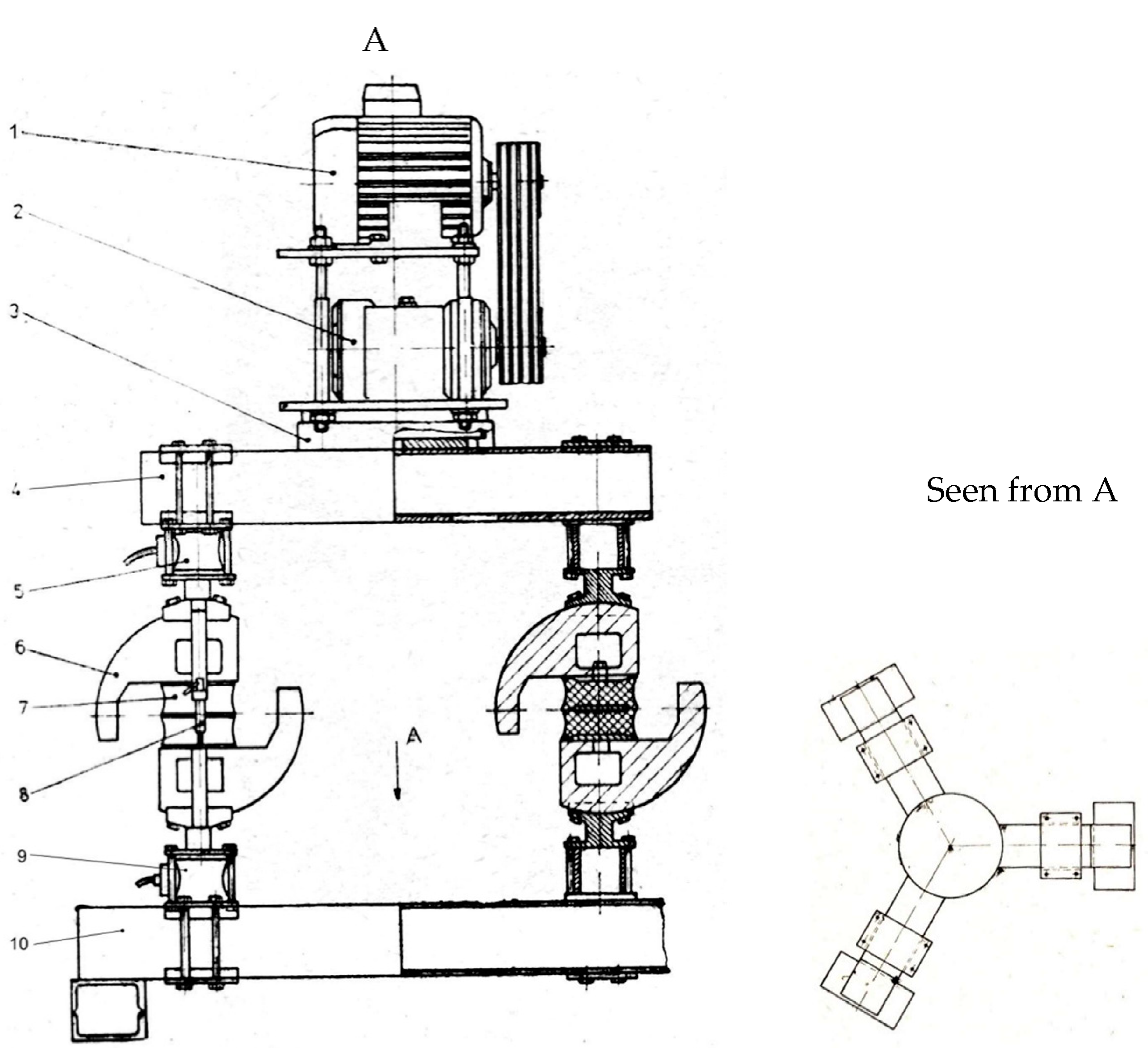
Figure 1 presents the construction solution of the stand with three test groups arranged at 120° so that the vertical excitation force may be applied equally to each elastomeric insulator. The following notations were used in
Figure 1: 1—variable speed drive electric engine; 2—unidirectional vibrator; 3—adjustment and fixing support; 4—upper beam; 5—force transducer
Tf; 6—semi-circular clamping device; 7—elastomeric insulator; 8—displacement transducer
Tx; 9—force transducer
Tq; 10—fixed base (frame) [
16,
17,
18,
19,
20].
The inertial vibrator generates a vertical force, harmonic with parallel and symmetrical action direction in relation to the three elastomeric insulators connected in parallel. Transducer Tf measures the incident force on the elastomeric insulator, transducer Tq measures the emergent force, or the force transmitted at the base and transducer Tx measures the instantaneous displacement x = x(t) or the vertical deformation of the deformable assembly. Each column has its own system of transducers Tx si Tf.
The principle schematization of the stand in constructive solution is presented in
Figure 2 where the following notations were used: 1—unidirectional vibrator mounted on upper structure; 2—force transducer (tensometric dose) input; 3—upper semi-circular guiding device and radial positional indexing; 4—upper device for holding the elastomeric insulator; 5—elastomeric insulator; 6—lower device for holding the elastomeric insulator; 7—lower semi-circular device for guiding and radial positional indexing; 8—force transducer (tensometric dose) output; 9—fixed base.
It is shown that the force transducer 5 and the displacement transducer 7 in
Figure 1, are mounted and maintained in the initial mechanical state, regardless of any modifications of the angular position of group 6. This makes the initial calibration of the transducers uninfluenced by the subsequent states of the dynamic tests.
Figure 3 presents the schematic of the linear dynamic model, where
x =
x(
t) is the instantaneous displacement;
F =
F(
t) harmonic excitation force;
m—mass of the mobile assembly;
Q =
Q(
t)—the force transmitted to the base;
k—stiffness of the insulator in the vertical direction;
c—viscous damping;
Tf—the incident force transducer which measures force
F(
t);
Tq—the displacement transducer that measures the instantaneous displacement
x =
x(
t).
The significant positions of the elastomeric insulator are presented in
Figure 4 where the axes of the fixed system are
Ox and
Oy, and the moving axes
Oc, for compression, and
Of, for shear, are connected to the elastomeric device. The three distinct positions are highlighted by the seating angle
α. Thus, for compression
α = 0, compression-shear
α > 0 and
α < 90, and for shear
α = 90° [
21,
22].
3. Evaluation of Dissipated Energy
Highlighting the modality of variation of the dissipated energy, in some well specified cases, is a criterion for optimizing the dynamic system based on the stationary harmonic regime and of the linear viscoelastic characteristics of the elastomeric insulators (stiffness
k and viscous damping
c) [
22]. In this case, for a dynamic regime with relative pulsation
, where
ω is the excitation pulsation and
ωn is its own pulsation, the dissipated energy
Wd may be expressed as:
where
is damping rate or the fraction of the critical damping (where
, where
c—effective viscous damping, and
cr—critical viscous damping). Usually,
is under the value of 0.7;
k—system stiffness, N/m;
m0r—static moment of the exciter with eccentric bodies in rotation motion, kg·m;
m—mobile mass of the stand, kg;
The maximum dissipated energy in the ante-resonance regime
corresponds to a fraction of the critical damping
, so it may be written as:
where
is the ante-resonance relative pulsation.
The maximum dissipated energy in the post-resonance regime
corresponds to pulsation
and to the fraction of the critical damping
, so that we have
The dissipated energy in the resonance regime
corresponds to pulsation
and to the fraction of the critical damping
, so that we have
From Relations (2), (4) then from Relations (3) and (4), it emerges the following correlations
The correlation between
and
emerges from Relations (5) and (6) as
3.1. Dissipated Energy as a Function of Damping
For the current variable with mentioned at constant value, we have the following situations, that is:
- (a)
ante-resonance with Ωa< 1 for which we have
- (b)
Post-resonance with Ωp > 1 for which it is valid the relation
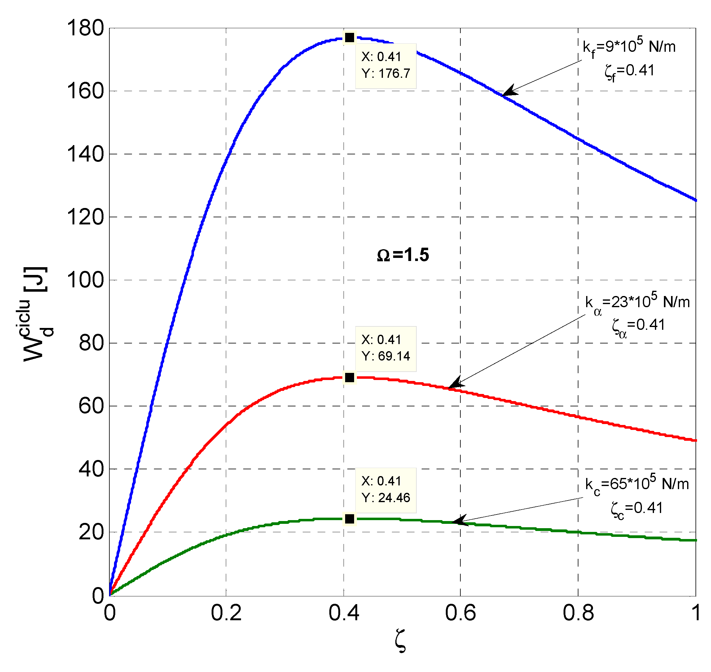
The three curves in
Figure 5 and
Figure 6 correspond to the cases in which the elastomeric anti-vibration devices, required for compression with
kc, compression—shear
kα and shear
kf are characteristic of the ante-resonance regime
and, respectively, of the post-resonance regime
[
23,
24].
3.2. Dissipated Energy as a Function of Relative Pulsation
The energy dissipated per cycle
Wdciclu(Ω) depending on the relative excitation pulsation
for the given values of stiffness
k and the fraction of the critical damping
is given by relation, with the parameter order
i, so
where
i = 1, 2, …,
n represents the index of the parametric order
which describes a curve from the curve family with current variable Ω [
23,
24].
Figure 7 shows the curve family with discrete values
and the continuous variation of Ω.
The relative pulsation Ω
i can also be written as
where,
ki is the stiffness for
i =
c,
α,
f, for the three situations corresponding to angle
α = 0°,
α = 60°,
α = 90°, respectively, compression, compression—shear and shear.
As
kc >
kα >
kf, it emerges that the relative pulsations are in order Ω
c< Ω
α< Ω
f as shown in
Figure 7.
The raised curves in
Figure 5,
Figure 6 and
Figure 7 are obtained numerically, and the marked values are obtained experimentally in the stationary dynamic regime regulated and controlled especially for this purpose. The deviations of the experimental values in relation to those obtained numerically fall within the range −3–5%.
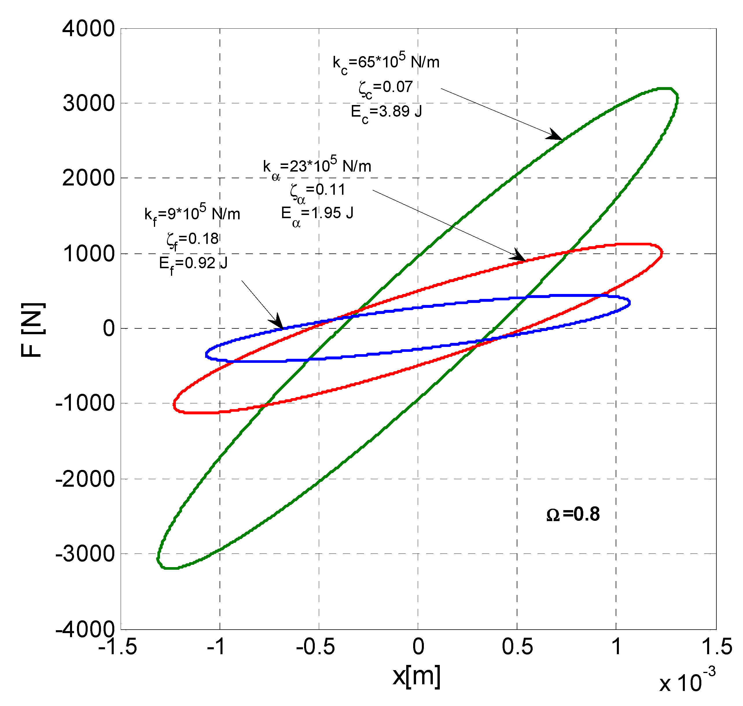
4. Hysteretic Loops
For the viscoelastic linear dynamic system, the hysteretic loops of elliptic shape can be represented for the dynamic excitation force F(t) in relation to deformation x = x(t) in coordinates F-x, as well as for the transmitted dynamic force Q = Q(t) depending on deformation x = x(t) in coordinates Q-x.
- (a)
Hysteretic loops in F-x coordinates
The equation of the elliptical hysteretic loops in the coordinate system
F-
x is given by the relation parameterized by
k and
discrete variable and
x continuous variable, so that
, the demonstration is given in the following papers [
24,
25].
Thus, we have
where
A =
A (Ω) is the amplitude of instantaneous displacement (deformation)
x =
x(
t).
Figure 8 for Ω
a= 0.8 in the ante-resonance regime presents the family of elliptical loops for the three significant cases of the viscoelastic system
,
and
that is in situation
,
and
. It is specified that all ellipses are inclined in quadrants I and III [
23,
24].
Figure 9 for Ω
p = 1.5 in the post-resonance regime presents the family of elliptical loops for the three significant cases, with the specification that all ellipses are inclined in quadrant II and IV as effect of the influence of the resonance regime [
23,
24,
25].
Figure 10 shows the elliptical hysteretic loops in resonance mode for the three significant cases.
It is found that the energy dissipated at resonance
Ec,
Eα and
Ef with the values in
Figure 10 coincides with the corresponding values in
Figure 7.
Figure 8 and
Figure 9 show the significant inertial effect in post-resonance with hysteretic loops in quadrants I and IV compared to the reduced inertial effect for pre-resonance with hysteretic loops found only in quadrants I and III.
- (b)
Hysteretic loops in Q-x coordinates
The equation of the elliptical hysteretic loops in coordinates
Q-
x is given by the equation parameterized by
k and
discrete variables and by the continuous variable
. In this case we have
where Ω is Ω
a < 1, Ω
p > 1 and Ω = 1 [
23,
24,
25].
In
Figure 11 at Ω
a = 0.8 in ante-resonance, for the three significant values and
,
and
it is presented as the family of elliptical loops, all inclined in quadrants I and III.
Figure 12 at Ω
p = 1.5 in post-resonance, for the three sets of significant values
,
and
there are presented the hysteretic loops in quadrants I and III.
Figure 13 for Ω = 1 at resonance presents the hysteretic loops for the three sets of significant data. It is found that the areas of the elliptical hysteretic loops are the same as the ones in
Figure 10 in the
F-
x system at resonance.
5. Conclusions
Based on the analysis of the analytical relations established both for the dissipated energy as well as for the representation of the hysteretic loops specific to the linear viscoelastic system that models a dynamic stand for elastomeric anti-vibration devices, the following conclusions can be drawn:
- (a)
The analytical expression of the dissipative energy offers the possibility of evaluation for two significant cases, namely:
- -
The variation of the dissipated energy depending on the discrete change of the damping for the three dynamic regimes: ante-resonance, post-resonance and resonance;
- -
The variation of the dissipated energy depending on the variation of Ω for discrete variable sets of values of k and ;
- (b)
The representation of the elliptical hysteretic loops in the F-x coordinate system for the three cases of the dynamic regimes, namely: ante-resonance, post-resonance and resonance. It was found that in post-resonance the inclination of the axes of the ellipses towards the ante-resonance regime changes due to the inertial effect of the mass, and in resonance, the ellipses are symmetrically centered in relation to the F-x axis system.
- (c)
The elliptical hysteretic loops in the Q-x system are inclined only in quadrants I and III, regardless of the dynamic regime.
- (d)
The areas of the ellipses represent the dissipated energy. The numerical results were verified by experimental lifting of hysteretic loops on the dynamic stand.
The experimental values were verified in accordance with those numerically determined by hysteretic loops with deviations of −3–5%.
Author Contributions
Conceptualization, P.B.; methodology, P.B.; software, N.D.; validation, P.B., C.D., N.D.; formal analysis, C.D.; investigation, C.D.; data curation, N.D.; writing—original draft preparation, P.B. All authors have read and agreed to the published version of the manuscript.
Funding
This research received no external funding.
Institutional Review Board Statement
Not applicable.
Informed Consent Statement
Not applicable.
Data Availability Statement
Not applicable.
Conflicts of Interest
The authors declare no conflict of interest.
References
- Dobrescu, C. The Rheological Behaviour of Stabilized Bioactive Soils during the Vibration Compaction Process for Road Structures. In Proceedings of the 22th International Congress on Sound and Vibration, Florence, Italy, 12–16 July 2015. [Google Scholar]
- Chen, B.J.; Lin, S.B.; Tsai, C.S. Theoretical and Experimental Study of High Damping Rubber Bearings. In Proceedings of the Seismic Engineering 2001, the 2000 ASME Pressure Vessels and Piping Conference, Seattle, WA, USA, 23–27 July 2000; Russel, G., Ed.; Volume 2. [Google Scholar]
- Kelly, J.; Konstantinidis, A.D. Mechanics of Rubber Bearings for Seismic and Vibration Isolation; John Wiley & Sons, Ltd.: Chichester, UK, 2011. [Google Scholar]
- Delfosse, C.G. Étude des vibrations linéaires d’un systeme mecanique complexe par méthode des mates normaux. Ann. L’ITBTP 1976, 336, 122–136. [Google Scholar]
- Giacchetti, R. Fondamente di Dinamica Delle Strutture e di Ingineria Sismica; EPC Libri: Roma, Italy, 2004. [Google Scholar]
- Kramer, H. Angewandte Baudynamic; Ernst & Sohn: Berlin, Germany, 2007. [Google Scholar]
- Bratu, P. Rheological model of the neopren elements used for base isolation against seismic actions. Mater. Plast. 2009, 46, 288–294. [Google Scholar]
- Rao, M. Mechanical Vibrations; Addison-Wesley Pub. Co.: Boston, MA, USA, 1995. [Google Scholar]
- Sireteanu, T.; Giuclea, M.; Mitu, A.M. An analitical approach for approximation of experimental hysteretic by Bouc.-Wen model. Proc. Rom. Acad. Ser. A 2009, 10, 43–54. [Google Scholar]
- Le Tallec, P. Introduction à la Dynamique des Structures; Cépaduès: Toulouse, France, 2000. [Google Scholar]
- Trigili, G. Introduzione alla Dinamica delle Strutture e Spettri di Progeto; Dario, F., Ed.; Laccorio: Palermo, Italy, 2010. [Google Scholar]
- Radeș, M. Mechanical Vibrationes; Ed. Printech: București, Romania, 2006. [Google Scholar]
- Stanescu, N.D. Vibrations of a shell with clearances, neo-Hookean stiffness, and harmonic excitations. Rom. J. Acoust. Vib. 2016, 13, 104–111. [Google Scholar]
- Vasile, O. Active vibration control for viscoelastic damping systems under the action of inertial forces. Rom. J. Acoust. Vib. 2017, 14, 54–58. [Google Scholar]
- Inman, D. Vibration with Control; John Wiley & Sons Ltd.: London, UK, 2007. [Google Scholar]
- Bratu, P. Stand for Measuring Perturbing Force. Patent No. 74754/1980, 17 June 1980. [Google Scholar]
- Marioni, A. Sistemi di Isplamento Sismico Innovetivi Prodotti dalla Societa ALGA. In Moderni Sistemi e Tecnologie Antisismici. Una Guida per il Progettista; 21mo Secolo: Milano, Italy, 2008. [Google Scholar]
- Dobrescu, C.F. Analysis of Dynamic Earth Stiffness depending on Structural Parameters in the Process of Vibration Compaction. Rom. J. Acoust. Vib. 2019, 16, 174–177. [Google Scholar]
- Dobrescu, C.F. Dynamic Response of the Newton Voigt–Kelvin Modelled Linear Viscoelastic Systems at Harmonic Actions. Symmetry 2020, 12, 1571. [Google Scholar] [CrossRef]
- Dobrescu, C.F. Evaluation of the dynamic compaction effect with vibrating rollers based on the rheological behaviour of soil. Acta Tech. Napoc. 2020, 63, 191–196. [Google Scholar]
- Spânu, G.; Drăgan, N. Gradul de Izolare a Reazemelor Elastomerice. Modelul Voigt-Kelvin. In Proceedings of the Buletinul celui de-al XXIII-lea Simpozion Naţional de Utilaje Pentru Construcţii SINUC 2017 (CD), Universitatea Tehnică de Construcţii, Bucureşti, Romania, 3 November 2017. [Google Scholar]
- Spânu, G.; Drăgan, N. Analiza Dinamică a Sistemelor 1DOF cu Reazeme Elastomerice. Modelul reologic Maxwell. In Proceedings of the Buletinul Celui de-al XXIII-lea Simpozion Naţional de Utilaje Pentru Construcţii SINUC 2017 (CD), Universitatea Tehnică de Construcţii, Bucureşti, Romania, 3 November 2017. [Google Scholar]
- Mortelli, A.; Sannino, U.; Parducii, A.; Braga, F. Moderni Sistemi e Tecnologie Antisismici; 21/mo Secolo: Milan, Italy, 2008. [Google Scholar]
- Naeim, F.; Kelly, J. Design of Seismicisolated Structures; John Wiley & Sons, Inc.: Hoboken, NJ, USA, 1999. [Google Scholar]
- Bratu, P. Hysteretic Loops in Correlation with the Maximum Dissipated Energy for Linear Dynamic Systems. Symmetry 2019, 11, 315. [Google Scholar] [CrossRef] [Green Version]
| Publisher’s Note: MDPI stays neutral with regard to jurisdictional claims in published maps and institutional affiliations. |
© 2022 by the authors. Licensee MDPI, Basel, Switzerland. This article is an open access article distributed under the terms and conditions of the Creative Commons Attribution (CC BY) license (https://creativecommons.org/licenses/by/4.0/).


