Article

Polyazulene Based Materials for Heavy Metal Ions Detection. 4. Search for Conditions for Thiophen-Vinyl-Pyridine-Azulene Based CMEs Preparation

by
Eleonora-Mihaela Ungureanu
1,
Veronica Anăstăsoaie
1,2,
Magdalena-Rodica Bujduveanu
1,
Alina-Giorgiana Brotea
1,
Raluca Isopescu
1 and
Gabriela Stanciu
3,*
1
Doctoral School Applied Chemistry and Material Science, Faculty of Applied Chemistry and Materials Science, University “Politehnica” of Bucharest, Gheorghe Polizu 1-7, 011061 Bucharest, Romania
2
National Institute for Research and Development in Microtechnologies, 126A, Erou Iancu Nicolae Street, 077190 Voluntari, Romania
3
Department of Chemistry and Chemical Engineering, Ovidius University of Constanta, 124 Mamaia Blvd, 900527 Constanta, Romania
*
Author to whom correspondence should be addressed.
Symmetry 2022, 14(2), 225; https://doi.org/10.3390/sym14020225
Submission received: 21 December 2021 / Revised: 12 January 2022 / Accepted: 14 January 2022 / Published: 24 January 2022

Abstract

:
The present work is connected to the study of electrode conditioning issues for the chemically modified electrodes (CMEs) prepared based on 2,6-bis((E)-2-(thiophen-2-yl)vinyl)-4-(5-isopropyl- 3,8-dimethylazulen-1-yl) pyridine (L). L is irreversibly electrooxidized to polymers leading to L-CMEs. The recognition experiments are the final test of chosen parameters (electropolymerization potential and charge in controlled potential electrolysis (CPE), anodic limit of the overoxidation cycles (OC), number of OC, anodic limit of the equilibration cycles (EC), number of EC, pH of the buffer solutions for HMs accumulation, complexation time, potential and time of reduction). The evidence of film deposition resulted by the change of ferrocene symmetrical signal characteristics on bare electrode in ferrocene solution was the simplest way to prove the formation of L-CMEs. However, finding the best electrode equilibration conditions turned out to be a source of increasing the analytical performance for the CMEs, especially those dedicated to the detection of Pb. The paper underlines the importance of understanding the role of each varied parameter, and of carrying out a systematic study of each possible variable. Optimum conditions for Pb ions analysis, using this new thiophen-vinyl-pyridine-azulene based CMEs, have been established, in order to get the best conditions for its detection in water.

1. Introduction

Azulene compounds have some specific characteristics that make them attractive for the synthesis of new functional materials [1]. Their properties recommend them for their nonlinear optical and photorefractive applications [2], for the fabrication of the lithium batteries cathode [3], or for organic materials-based light emitting diodes [4]. Azulenes are polar organic compound. They contain the following two condensed cyclic moieties: one moiety has seven carbon atoms (electron-poor), and the other one five carbon atoms (electron-rich) [5]. Most azulene derivatives present an irreversible electrooxidation leading to polymers. CMEs obtained in this way can be used to build electrochemical sensors, as shown in our previous works [6,7]. This straightforward approach is not common in the attempt of trace metals detection. Some examples can be mentioned [7,8,9,10]. CMEs with complexing properties are alternative tools for the recognition of HMs ions, which is usually done by very sensitive methods, as follows: inductively coupled mass spectrometry [11], atomic absorption spectroscopy [12], cold vapor atomic fluorescence spectrometry [13], and emission spectroscopy [14]. Electrochemical techniques have received attention and have promising applications for biological and environmental analysis, due to their low cost, simplicity, sensitivity, selectivity, and fast response [7,8,9,10,15]. To get complexing CMEs, the most efficient preparation is the direct electropolymerization of a complexing monomer [16]. Such functional materials have been the aim of the research performed lately in our group, in order to prepare modified electrodes for HMs ions detection by using complexing modified electrodes based on azulene derivatives. Our research group developed CMEs based on several azulene structures (thiadiazoles, tetrazoles, pyridines, crown ethers) that were used to obtain sensors for HMs. For instance, the azulene-tetrazoles gave very good results in HMs detection. CMEs based on E-5-((6-t-butyl-4,8-dimethylazulen-1-yl) diazenyl)-1H-tetrazole (L1) were prepared on glassy carbon electrode [7]. The ability of L1-CMEs to complex Cd(II), Pb(II), Cu(II) and Hg(II) cations in aqueous solutions with concentrations between 10−9 and 10−4 M has been proved. It was shown that L1-CMEs can be successfully used to develop electrochemical sensors for the determination of Pb(II) and Cd(II) ions. The response was linear between 10−9 and 10−8 M for Pb(II) and 10−7 to 10−6 M for Cd(II), respectively. Pb(II) slope of 1.112 VA/M indicates a bigger sensitivity for this ion, which had the most intense analytical signal. The detection limit for Pb(II), estimated at 10−9 M, can be optimized. The limit obtained for Pb using CME based on L1 is lower than that obtained with other azulene ligands. Hence, the importance of ligand structure in the design of molecular sensors. Comparative studies performed for complexation in solution show the strong influence of asymmetric immobilization of the ligand by electropolymerization. The electrochemical study of E-5-((5-isopropyl-3,8-dimethylazulen-1-yl) diazenyl)-1H-tetrazole (L2) showed the formation of thin films [17]. Recognition of heavy metal ions using L2-CME was performed for concentrations between 10−8 and 10−4 M. Pb(II) and Hg(II) ions showed the best signals. The detection limit was estimated at 10−8 M for Pb(II) ion. UV-Vis absorption spectra of L2 solutions in the presence of heavy metal ions confirmed the formation of Me(II)(L2)2 complexes with Pb(II) and Hg(II). Voltametric techniques and UV-Vis spectroscopy have shown that L2 can be used to detect Pb(II) and Hg(II) ions by these methods. This is of interest for the analysis of these ions in various water samples. The detection limits obtained for HMs using CMEs based on different azulene ligands are still under study, and the conditions for CMEs preparation are being optimized.
To develop new sensors for HMs ions, 2,6-bis((E)-2-(thiophen-2-yl)vinyl)-4-(5-isopropyl-3,8-dimethylazulen-1-yl) pyridine (L) has been synthesized [18] and characterized [19] by electrochemical techniques. The aim of the present paper is the study of complexing L-CMEs preparation in view of HM ions (Cd, Pb, Cu, Hg) detection. The subject of this work is related to the electrode conditioning issues for CMEs prepared from L. The recognition experiments are the final test of chosen parameters.

2. Materials and Methods

The ligand L (Figure 1) was synthesized according to the previously published procedure [11]. Electrochemical oxidation of L, in view of CMEs preparation, was done in acetonitrile (CH3CN, Sigma Aldrich, Taufkirchen, Germany, electronic grade 99.999% trace metals) containing 0.1 M tetrabutylammonium perchlorate (TBAP, Fluka, Munich, Germany, analytical purity ≥99.0%), and used as solvent and supporting electrolyte, respectively. Stock solutions of Cd, Pb, Cu and Hg (10−2 M) have been freshly prepared before each experiment, using cadmium(II) acetate dihydrate (Fluka, Munich, Germany, ≥98%), lead(II) acetate trihydrate (Fluka, Munich, Germany, ≥99.5%), and mercury(II) acetate and copper(II) acetate monohydrate (Fluka, Munich, Germany, ≥98%). Buffer acetate solutions have been prepared from 0.2 M acetic acid (Fluka, Munich, Germany, >99.0%, trace select) solution and 0.2 M sodium acetate solution (Roth, Karlsruhe, Germany, 99.99%).
Electrochemical experiments have been performed using the PGSTAT 12 AUTOLAB (Metrohm/Eco Chemie, Utrecht, The Netherlands), connected to a three-electrode cell. Glassy carbon disk (with 3 mm diameter, Metrohm, Herisau, Switzerland) and L-CMEs were used as working electrodes for characterization and recognition experiments, respectively. The auxiliary electrode was a platinum wire, while the reference electrode was either Ag/10 mM AgNO3 in 0.1 M TBAP/CH3CN (in electrochemical experiments performed in for acetonitrile solutions), or Ag/AgCl, 3 M KCl (in electrochemical experiments performed in for water solutions). In experiments performed in acetonitrile solutions, the potentials were finally referred to the potential of the ferrocene/ferricenium redox couple (Fc/Fc+) equal to +0.07 V.
For each experiment, the glassy carbon electrode was prepared by polishing it with diamond paste (2 µm) and washed with the solvent before each experiment and cleaned with the solvent. The electrochemical characterization was based on differential pulse voltammetry (DPV), cyclic voltammetry (CV), and rotating disk electrode (RDE). A scan rate of 0.1V/s was usually used in the CV experiments. Curves were usually recorded at the scan rate of 0.1 V/s. In the DPV method the curves were recorded at 0.01 V/s (at pulse height of 0.025 V, and step time of 0.2 s). RDE curves were recorded at 0.01 V/s at different rotation rates. All experiments were performed at 25 °C, under argon atmosphere.
Electrochemical experiments for HMs ions detection were done on L-CMEs using a supporting electrolyte consisting in 0.1 M buffer acetate solution in water, at 25 °C, under argon atmosphere. Various HMs concentrations (10−4 M–10−7 M) were tested. These solutions were prepared starting from the stock solutions (10−2 M), by successive dilutions in 0.1 M buffer acetate (pH 4.5). The modified electrodes were equilibrated and overoxidized in 0.1 M acetate buffer solutions (pH 4.5). The conditions of equilibration and overoxidation were varied as number of CV cycles, and anodic potential limits. After equilibration and overoxidation, each of the electrodes was immersed in the solution where HMs ions (Cd(II), Pb(II), Cu(II), and Hg(II)) were present, each of them at 10−5 M concentration and kept for an established time. Then, it was rinsed with distilled water, wiped with filter paper, and placed in a freshly prepared 0.1 M acetate buffer solution of known pH. A reduction potential for a defined period was applied, followed by a sweep by DPV to +0.8 V. The resulting DPV curves were examined, and the DPV peaks were characterized as current and potential. The dependences of the stripping peak current for each investigated cation were plotted as function of each variable parameter.

3. Results

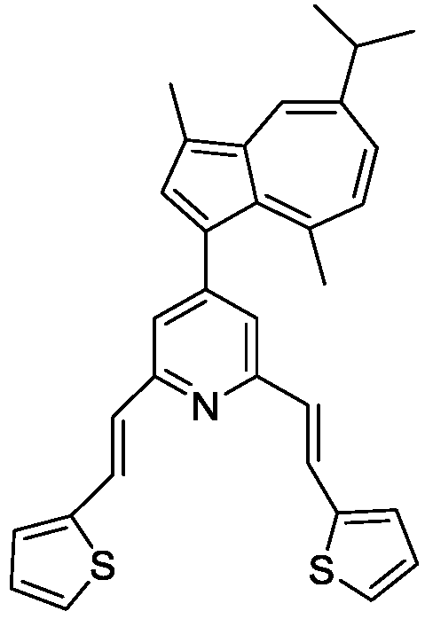
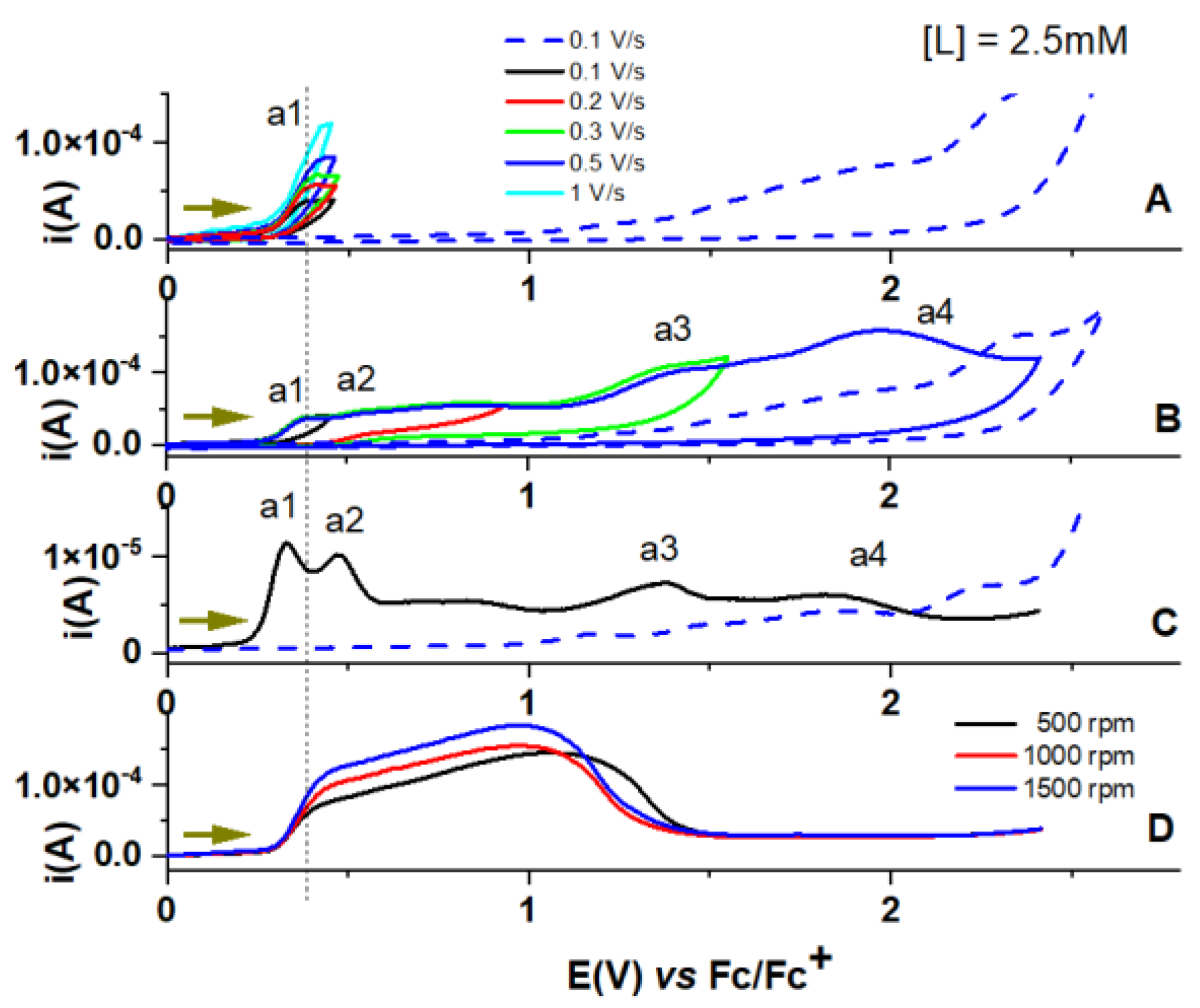
3.1. Electrochemical Oxidation of L

The CV, DPV, and RDE oxidation curves recorded in L solutions in 0.1 M TBAP/CH3CN, starting from the stationary potential are shown in Figure 2.

3.2. L-CMEs Preparation

L-CMEs were obtained using millimolar solutions of L in 0.1 M TBAP/CH3CN, either by successive potential scans, or by controlled potential electrolysis (CPE). The modified electrodes were introduced in a ferrocene solution (1 mM) in 0.1 M TBAP/CH3CN. The ferrocene signal of the modified electrode was different from the ferrocene signal on the bare electrode (Figure 3). The change indicates the electrode covering with films formed by electrooxidation, fact also confirmed by the electrode colour change.

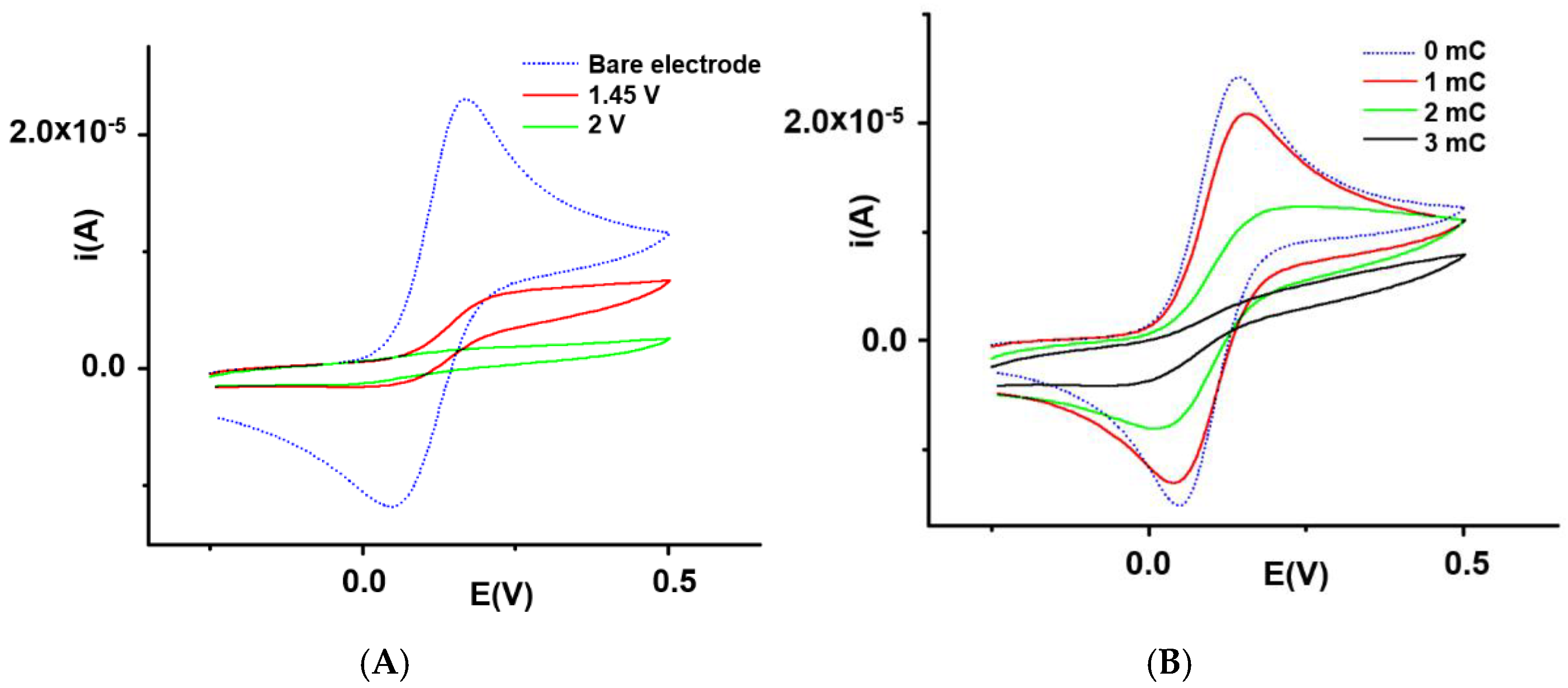
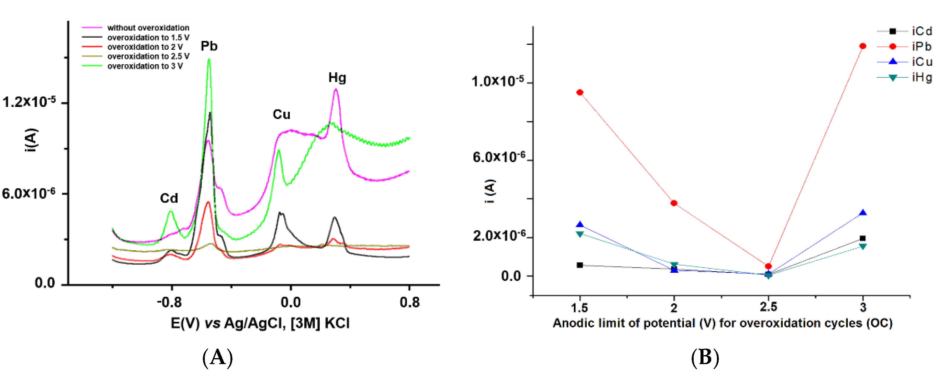
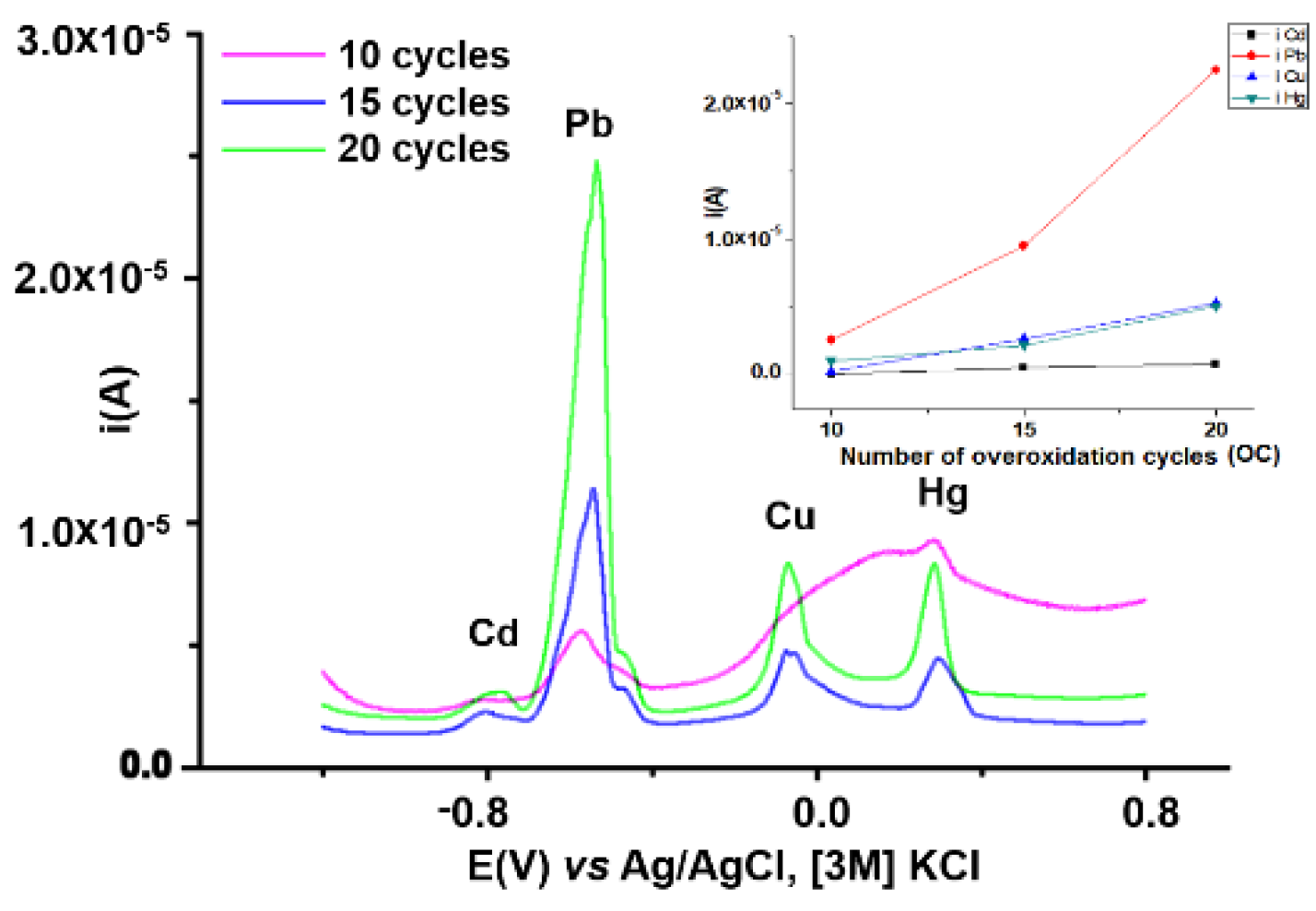
3.2.1. Influence of Overoxidation Conditions on HMs Analyses

The first parameter varied to optimize the overoxidation conditions from conditioning step was the anodic limit in the CV overoxidation cycles(OC). L-based modified electrodes were prepared by CPE (+2 V, 3 mC), in similar conditions. The electrodes were conditioned in acetate buffer solution of pH 5.5, under identical equilibration conditions (15 CV cycles between −0.9 V and +0.6 V), and overoxidized by 15 CV cycles between −0.2 V and different anodic potential limits (+1.5, +2, +2.5, +3 V). After conditioning and overoxidation, the electrodes were immersed for 15 min in a solution that contains HMs ions (Cd(II), Pb(II), Cu(II), and Hg(II)), each at 10−5 M concentration, then rinsed, wiped with filter paper, and placed in a freshly prepared acetate buffer solution of pH 5.5. The reduction potential of −1.2 V was applied for 3 min, and then a sweep by DPV from −1.2 V to +0.8 V. The resulting DPV curves are presented in Figure 4. Figure 4B shows the dependences of the peak currents for each cation, on the anodic limit of overoxidation scans (OC). It results that a potential limit of +1.5 V for overoxidation is the best one for all stripping currents.
The second parameter in the optimization of overoxidation conditions was the number of CV cycles of overoxidation (OC). Modified electrodes were prepared as mentioned before by CPE (+2 V, 3 mC). They were similarly conditioned in acetate buffer solution of pH 5.5 under identical equilibration conditions by 15 CV cycles between −0.9 V and +0.6 V, and overoxidized between −0.2 V and +1.5 V, using various number of cycles of overoxidation, as follows: 10, 15, 20. After that, they were immersed for 15 min in the solution containing (Cd(II), Pb(II), Cu(II), and Hg(II)), each at concentration of 10−5 M, rinsed, wiped, and placed in a freshly prepared acetate buffer solution of pH 5.5. The reduction potential of −1.2 V was applied for 3 min, and then a sweep by DPV from −1.2 V to +0.8 V. The DPV stripping curves are shown in Figure 5. The inset of Figure 5 shows the dependences of the peak currents for Cd, Pb, Cu, Hg on the number of cycles of overoxidation (OC). From the inset in Figure 5, it results that the most intense DPV signals were obtained for 20 CV cycles of overoxidation.

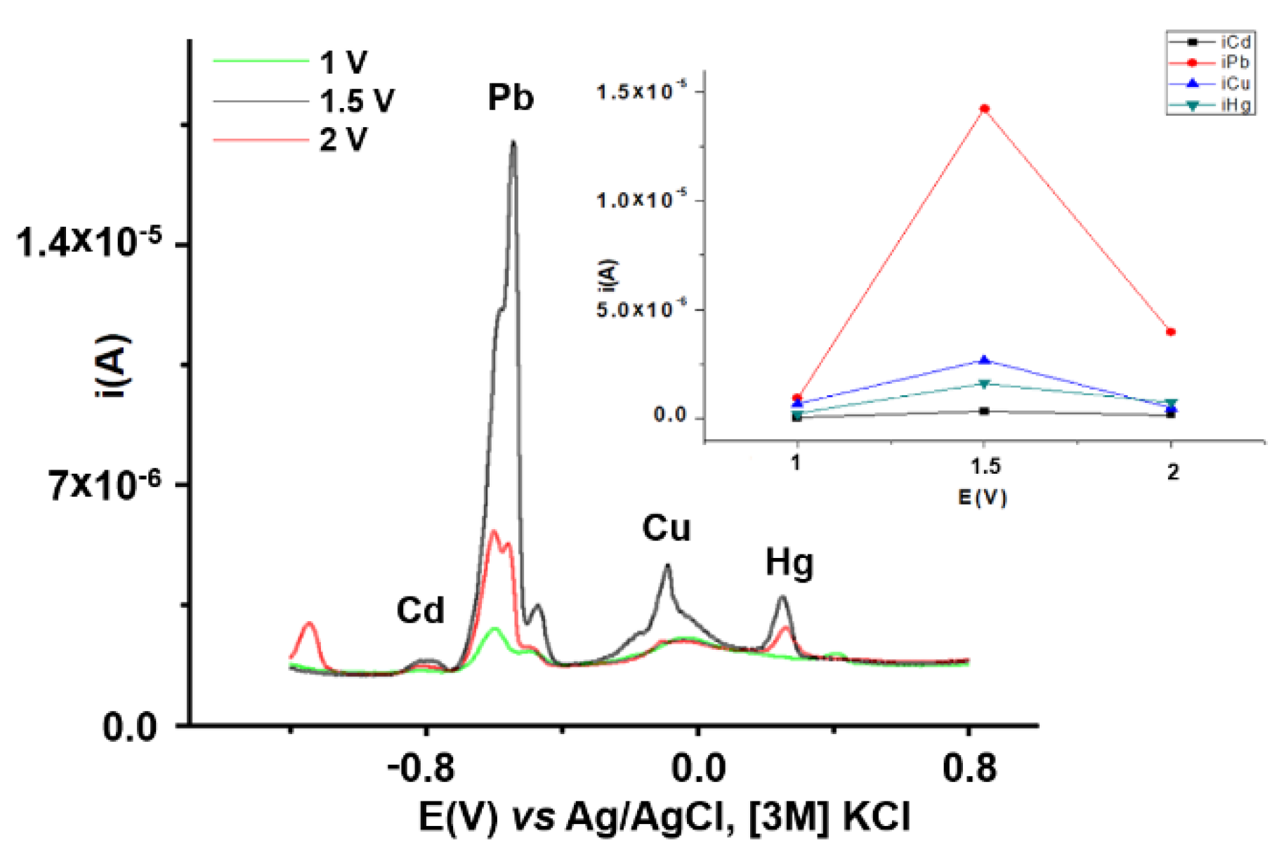
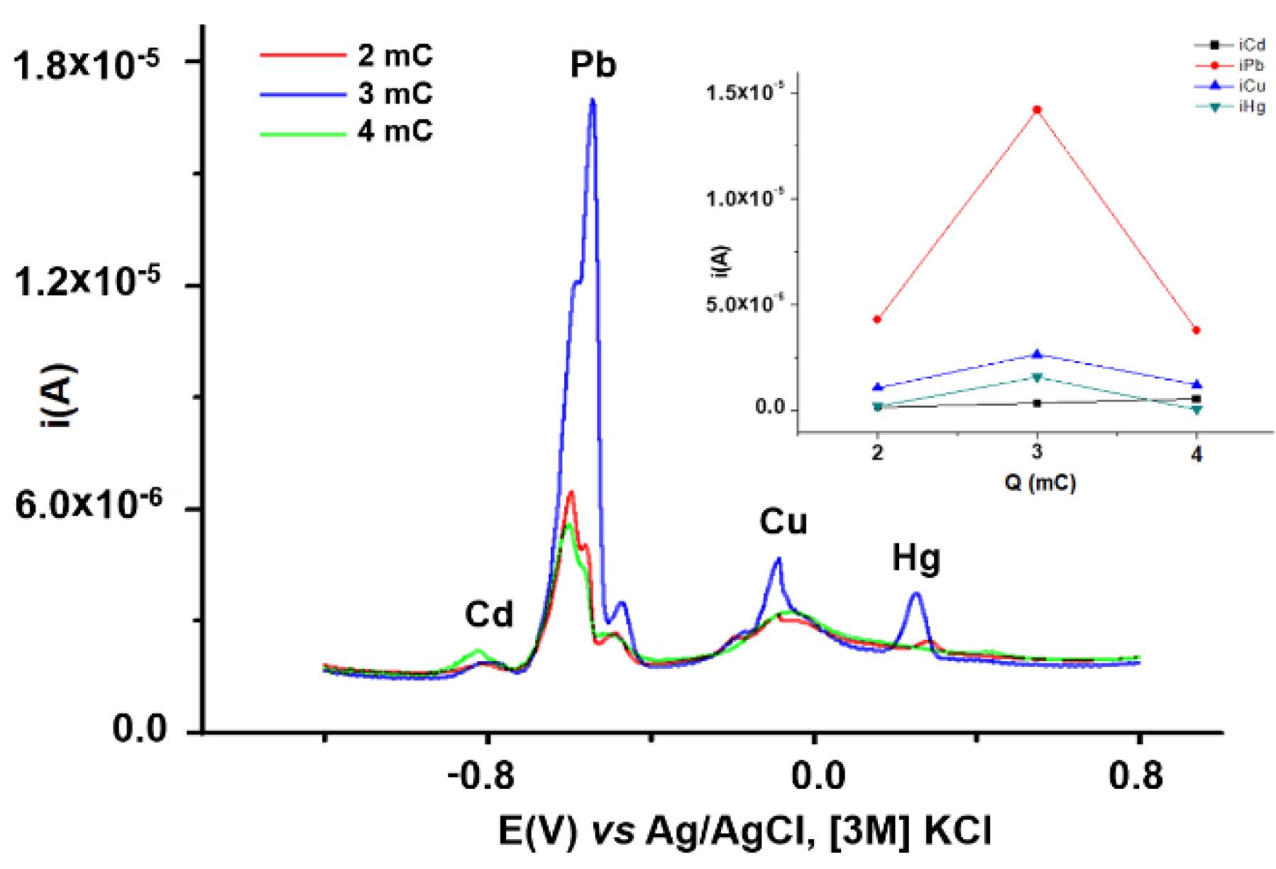
3.2.2. Influence of CPE Charge and Potential on HMs Analytical Signals

L-CMEs were prepared at different potentials and using variable amounts of electricity to determine the influence of L-CMEs preparation conditions.
After obtaining the films, the modified electrodes were conditioned in acetate buffer (pH 5.5) solution, in 15 CV cycles of equilibration between −0.9 V and +0.6 V, and overoxidized by 20 CV cycles between −0.2 V and +1.5 V. After that, the electrodes were immersed for 15 min in the solution containing HMs ions (Cd(II), Pb(II), Cu(II), and Hg(II)), rinsed, wiped, and placed in a freshly prepared acetate buffer solution of pH 5.5. The reduction potential of −1.2 V was applied for 3 min, and then a sweep by DPV from −1.2 V to +0.8 V. The curves of L-CMEs obtained using charges of 3 mC at different electropolymerizing potentials (1, 1.5, 2 V) are shown in Figure 6. From Figure 6 inset, it results that the highest signals were obtained at a potential of +1.5 V, which is the optimum potential. At this potential of +1.5 V, L-CMEs were prepared using different polymerization charges (Figure 7). Figure 7 inset shows the dependences of the peak currents for Cd, Pb, Cu, Hg on the polymerization charge. Figure 7 also shows that increasing the charge does not lead to a proportional increase in the signal.

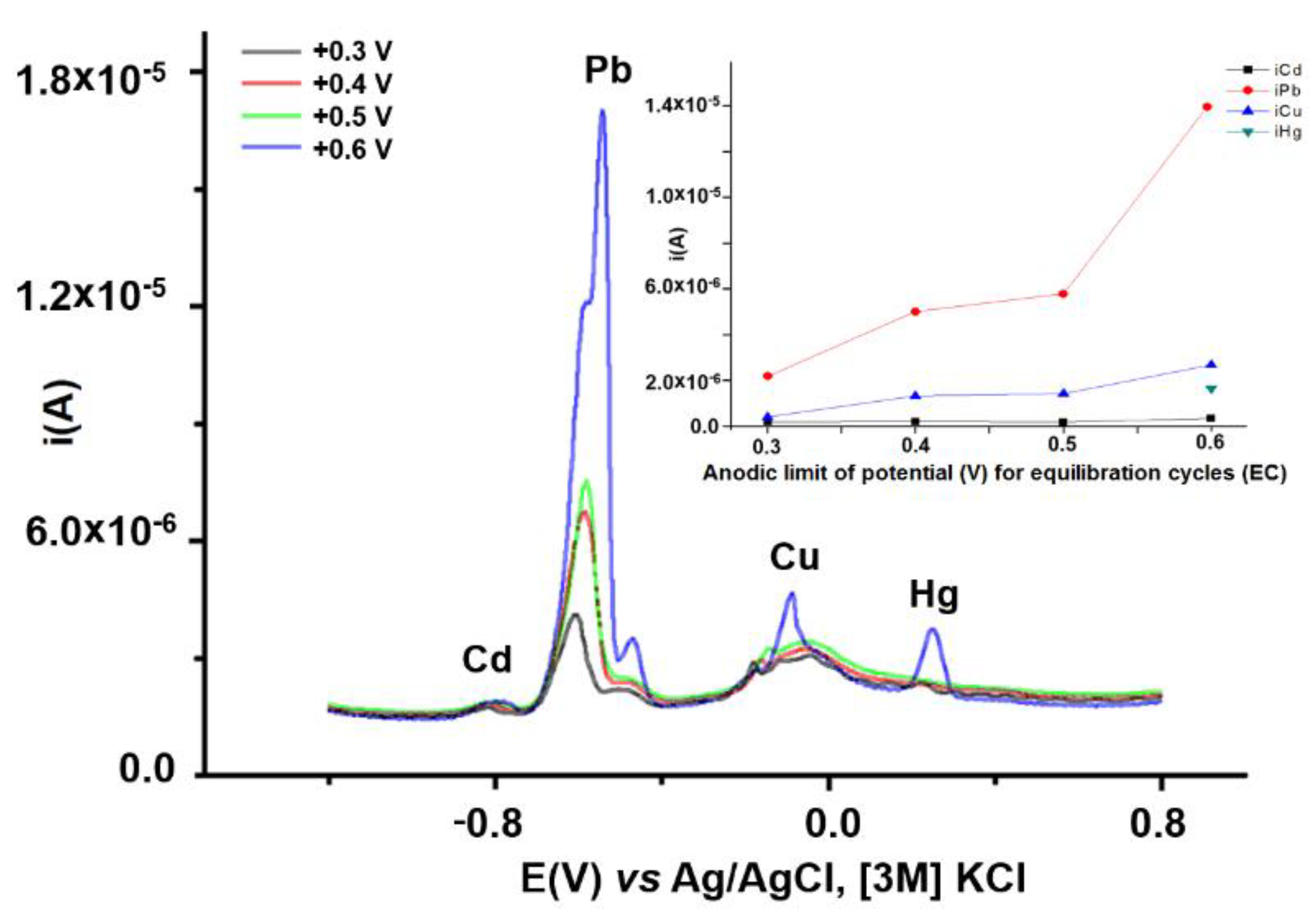
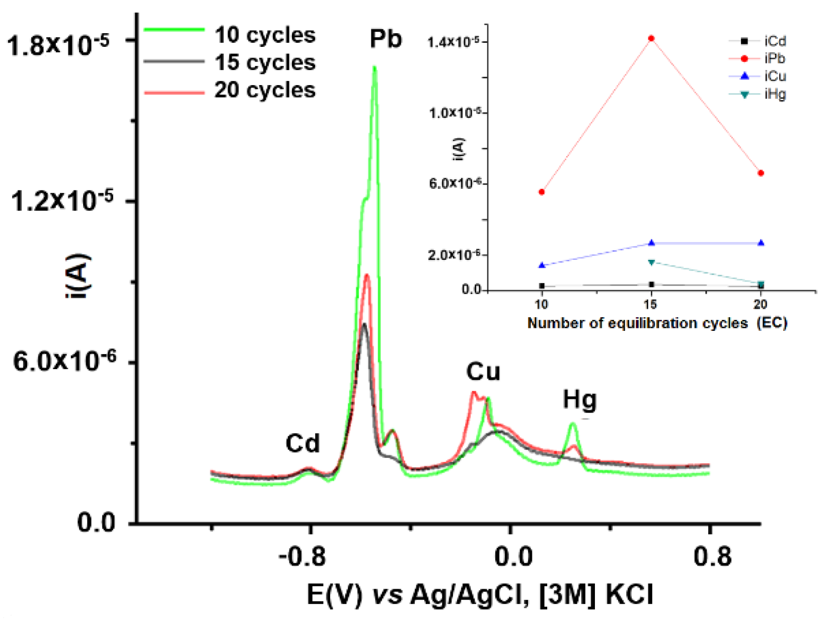
3.2.3. Influence of Equilibration Conditions on HMs Analytical Signals

Modified electrodes based on L were prepared in the optimum conditions resulted from the above presented in 3.2.1 experiments by CPE (+1.5 V, 3 mC). The electrodes were conditioned in an acetate buffer solution of pH 5.5 under different equilibration conditions by 15 CV cycles between −0.9 V and at different anodic potential limits (+0.3 V, +0.4 V, +0.5 V, +0.6 V). The overoxidation for each electrode was performed by 20 CV cycles between −0.2 V and +1.5 V. After that, the electrodes were immersed for 15 min in the accumulation solution containing Cd(II), Pb(II), Cu(II), and Hg(II), then rinsed, wiped, and placed in a freshly prepared acetate buffer solution of pH 5.5. The reduction potential of −1.2 V was applied for 3 min, and then a sweep by DPV from −1.2 V to +0.8 V.
The DPV stripping curves for L-CMEs equilibrated by CV (with different anodic limits between +0.3 V and +0.6 V) are shown in Figure 8. From the plots of the DPV currents for each cation (Figure 8 inset), it results that a potential limit of +0.6 V leads to a maximum for the stripping currents. Increased analytical signals for HMs by increasing the anodic overoxidation limit from +0.5 V to +0.6 V indicate that the monomer polymerization process continues during the film overoxidation. It results in extra attachment of monomer fragments present in the porous film initially formed on the GC surface, and therefore, an increase in analytical signal. This is an unexpected result connected to an apparently secondary parameter (such as equilibration potentials domain) of L-CMEs conditioning.
The next tested parameter with influence on HMs analytical signals was the number of the CV equilibration cycles (CE). L-CMEs were overoxidized at +0.6 V, using a variable number of cycles. The rest of conditioning was performed similarly in acetate buffer solution (pH 5.5), and the equilibration was between −0.9 V ÷ +0.6 V. The DPV stripping curves for the modified electrodes are shown in Figure 9. In Figure 9 inset the dependences of the peak currents for Cd, Pb, Cu, Hg on the number of equilibration cycles are represented. It results that the most intense DPV signals were obtained for 15 cycles. Figure 9 inset shows that an increasing of number of equilibration cycles does not lead to a proportional increase in the signal. This is also another unexpected result, connected to an apparently secondary parameter (number of equilibration cycles) of L-CMEs conditioning.

3.3. Establishing Favourable Conditions for Pb Analysis

The analysis of the results obtained from Section 3.2.1, Section 3.2.2 and Section 3.2.3 on the mixture of HM ions (Cd, Pb, Cu, Hg), indicates the best signal was obtained for Pb. All curves show that L-CMEs are selective for Pb, among the other investigated HMs. To improve the conditions for Pb analysis, the following parameters were varied: buffer pH, complexation time, potential and reduction time. The modified electrodes based on L were prepared on glassy carbon by CPE at 1.5 V, 3 mC, in a standard cell with 3 electrodes, in 2.5 mM L solution in 0.1 M TBAP, CH3CN, and conditioned using the optimal parameters that were established in Section 3.2.

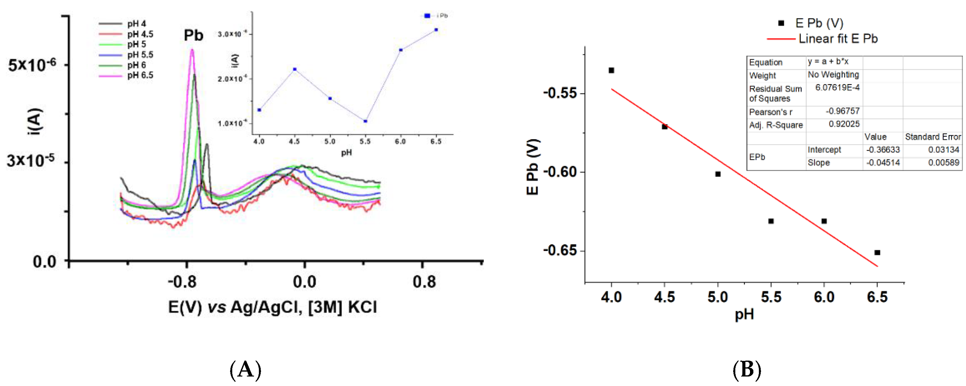
3.3.1. Influence of Conditioning Buffer pH on Pb Analysis

To assess the pH of the buffer in the accumulation step, test solutions with a concentration of 10−6 M Pb(II) were prepared for several pH-adjusted acetate buffer (between 4 and 6.5). The electrodes to be tested were equilibrated (15 CV cycles between −0.9 V and +0.6 V), and overoxidized (20 CV cycles between −0.2 V and +1.5 V), under the same conditions. Then, the electrodes were immersed for 15 min in a solution containing 10−6 M Pb(II), rinsed, wiped, and introduced in freshly prepared acetate buffer solution with a given pH. The reduction potential of −1.2 V was applied for 3 min, and then a sweep by DPV between −1.2 V and +0.8 V. From Figure 10A inset, it results that the Pb(II) DPV peak does not vary much with the pH of the buffer solution. The Pb(II) peak potential linearly decreases with pH, with the slope of 45 mV/decade (Figure 10B). Considering the intensity of the peak current, potential, as well as the symmetry of the obtained peaks, it can be estimated that the optimal pH is of 4.5.

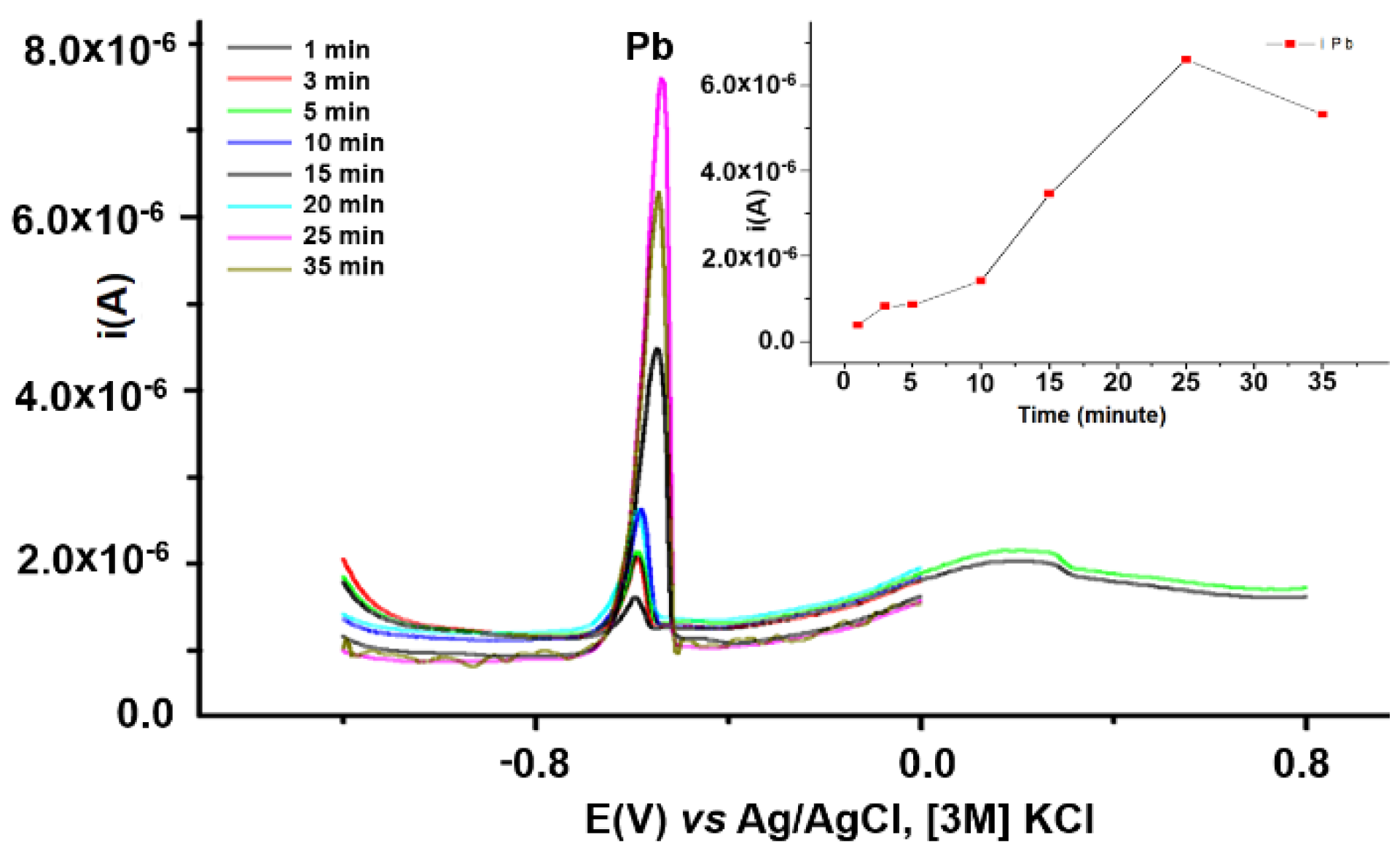
3.3.2. Influence of the Accumulation Time on Pb Analysis

To find the optimum complexation time, the modified electrodes based on L were conditioned in a solution of acetate buffer of pH 4.5 by 15 CV cycles of equilibration between −0.9V and +0.6V, and by 20 CV cycles of overoxidation between −0.2 V and +1.5 V. After that, the electrodes were immersed in a solution that contains 10−6 M Pb, for different accumulation times, then rinsed, wiped, and introduced in acetate buffer solutions of pH 4.5. The reduction potential of −1.2 V was applied for 3 min, and then, a sweep by DPV between −1.2 V and +0.8 V. Figure 11 inset shows the value of the Pb(II) peak current increases with the complexation time until it reaches a plateau value. The time of 25 minutes has been selected for Pb complexation.

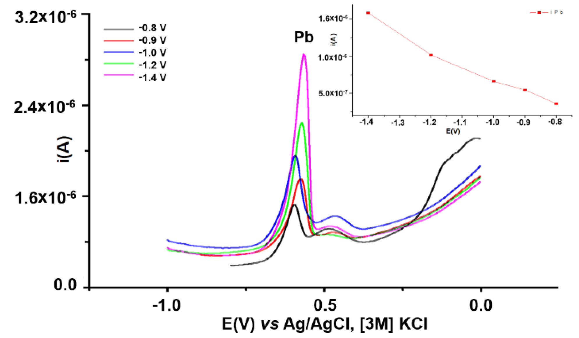
3.3.3. Influence of Reduction Potential on Pb Analysis

L-CMEs were conditioned as presented in Section 3.3.2. After equilibration and overoxidation, the electrodes were immersed for 15 min in solution that contains 10−6 M Pb(II), then rinsed, wiped, and placed in freshly prepared acetate buffer solutions of pH 4.5. A reduction was applied for 3 min at potentials of −0.8, −0.9, −1, −1.2, −1.4 V, respectively, followed by a sweep by DPV to +0.8 V. The resulting DPV curves for all the applied reduction potentials are plotted in Figure 12. Figure 12 inset shows the DPV currents for Pb(II) increase, as expected, as the applied cathodic potential increases. The applied potential of −1.4 V was chosen for the following step of optimization.

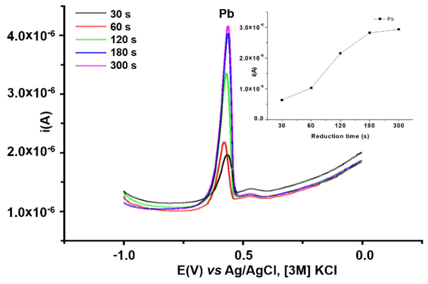
3.3.4. Influence of Reduction Time on Pb Analysis

L-CMEs were conditioned as presented in Section 3.3.2. After equilibration and overoxidation, the electrodes were immersed for 15 min in the solution containing 10−6 M Pb, then rinsed, wiped, and placed in freshly prepared acetate buffer solutions at pH 4.5. The reduction potential applied was of −1.4 V, for different reduction times. The sweeps by DPV to +0.8 V are shown in Figure 13. From Figure 13 inset it can be seen that Pb(II) current increases with the reduction time until it reaches a plateau value which corresponds to a reduction time of 180 s.

4. Discussion

In Figure 2, the CV, DPV, and RDE curves for L oxidation are given. Four oxidation peaks (a1–a4) can be noticed in the DPV curve (Figure 2C). Considering the structure of azulene derivative, the peak a1 can be attributed to the oxidation of azulene moiety to its radical cation. This is an irreversible oxidation, as seen from the dependence of a1 peak current on the scan rate (Figure 2A). The process a2 is also irreversible and leads to the covering of the electrode with insulating films. After a2 peak the currents in CV and DPV decrease to a plateau value (Figure 2B,C, respectively), and a sudden drop in RDE curves appears. The process a3 is irreversible too (see Figure 2B–D) and leads to a full covering of the electrode surface (after scanning over the potential of a3 the current drops to the baseline value). Such results can be rationalized by assuming the formation of the following two kinds of films: porous at potentials around a2, and compact, at potentials around a3. These assumptions are in connection with the results in Figure 3 [20].
Modified electrodes based on L have been prepared from millimolar solutions of L in 0.1 M TBAP/CH3CN either by successive potential scans, or by CPE. Their transfer in a ferrocene solution in 0.1 M TBAP/CH3CN shows different CV curves on the modified electrodes, in comparison with the ferrocene signal on the bare electrode (Figure 3). Both techniques for obtaining modified electrodes based on L resulted in films of different thicknesses (as seen in Figure 3). The ferrocene signal on modified electrode is altered differently when the preparation is done by scanning (Figure 3A) or CPE (Figure 3B). In Figure 3A the cathodic branch of the ferrocene signal disappears almost completely, while in Figure 3B it is present, even when the anodic branch vanishes; this can be the result of other structural polymer which is formed by scanning (at less positive potentials) than by CPE (at +2 V). The CPE technique was chosen further to prepare modified electrodes for this study of optimizing L-CMEs for HM analysis, since this technique strictly controls the film thickness. The higher the charge used in CPE, the flatter the signal of ferrocene, fact which denotes the formation of a thicker film (Figure 3B).
To see the influence of overoxidation conditions on HMs analyses the following parameters have been varied one after the other, when keeping all other conditions constant: anodic limit in the CV overoxidation cycles, number of CV overoxidation cycles, electropolymerization potential and charge in CPE, anodic limit in the CV equilibration cycles, and number of CV equilibration cycles.
From the DPV curves for L-CMEs obtained at different potentials, it results that the highest signals for all cations were obtained when the electrodes were prepared by CPE at a potential of +1.5 V, which leads to the highest DPV peaks for all cations. This potential is situated in the proximity of a3 peak, signalled in the electrochemical study of the ligand, and it corresponds to the formation of a film which is more porous than the one prepared at the potentials of the first anodic peaks. The values of DPV currents for all cations obtained when L-CMEs was prepared at +1.5 V, are five times higher than for the preparations made at potentials of +1 V or +2 V, which means that the films have different structures at the three investigated potentials.
At the optimum potential of 1.5 V, L-CMEs preparation using different polymerization charges resulted in a mean optimum charge of 3 mC. Increasing the charge more does not lead to a proportional increase in the signal. It appears that the complexing sites of the polymer are no longer accessible in the thicker films.
The study of the improvement of L-CMEs analytical parameters revealed that the equilibration step is very important in the increase of the analytical signals for all cations. From the analysis of the results obtained on the mixtures of Cd, Pb, Cu, Hg ions, the best signal was obtained for Pb. A refinement of conditions for lead analysis has shown that, by varying the buffer pH, complexation time, potential and reduction time, the analytical signal for Pb is confident, and it can be increased.

5. Conclusions

2,6-bis((E)-2-(thiophen-2-yl)vinyl)-4-(5-isopropyl-3,8-dimethylazulen-1-yl)pyridine (L) has been studied by electrochemical methods, to find the conditions for pyridine-azulene based CME preparation. The best potential for azulene polymerisation was identified. The new prepared modified electrodes are capable to be used in heavy metals recognition by preconcentration followed by anodic stripping. The best response has been obtained for Pb. The recognition experiments were the final test of investigated parameters (electropolymerization potential and charge in CPE, anodic limit of the overoxidation cycles (OC), number of OC, anodic limit of the equilibration cycles (EC), number of EC, pH of the buffer solutions for HMs accumulation, complexation time, potential and time of reduction). The evidence of film deposition by the change of ferrocene symmetrical signal characteristics on bare electrode in ferrocene solution could be the simplest way to prove the formation of L-CMEs. However, finding the best electrode equilibration conditions is a source of increasing the analytical performance for CMEs. The study of these L-CMEs revealed many unknown aspects. The analytical parameters can be improved by changing some parameters with apparently secondary importance. This underlines the importance of understanding the role of each varied parameter, and of carrying out a systematic study of each possible variable. The novelty elements brought by this paper connected to the conditioning issues for CMEs are of great importance for the improvement of the analytical performances of CMEs based on other azulene derivatives (thiadiazoles, tetrazoles, pyridines, crown ethers).

Author Contributions

Conceptualization, E.-M.U.; validation, E.-M.U. and G.S.; formal analysis, R.I., V.A., M.-R.B. and A.-G.B.; investigation, V.A., M.-R.B. and A.-G.B.; data curation, G.S., R.I.; writing—original draft preparation, V.A., M.-R.B. and A.-G.B.; writing—review and editing, E.-M.U. and G.S; supervision, E.-M.U., R.I. and G.S.; resources, G.S.; project administration, E.-M.U. All authors have read and agreed to the published version of the manuscript.

Funding

This research was funded by Romanian National Authority for Scientific Research, UEFISCDI, under grant PN-III-P2-2.1-PED-2019-0730, contract no. 293PED/2020.

Institutional Review Board Statement

Not applicable.

Informed Consent Statement

Not applicable.

Acknowledgments

The authors are grateful for the support from UEFISCDI Romanian projects ID PN-II-RU-TE-2014-4-0594, contract nr. 10/2014, PN-II-PT-PCCA-2013-4-2151 contract nr. 236/2014 and bilateral project France–Romania PN-III-P3-3.1-PM-RO-FR-2019-0309; and to Valentin STANESCU, Cecilia IORDACHE, and technician Ionut STANESCU from SC Analist SRL for their help in organizing activities and experiments work for the contract number 236/2014.

Conflicts of Interest

The authors declare no conflict of interest.

References

  1. Cristea, M.; Bîrzan, L.; Dumitrascu, F.; Enache, C.; Tecuceanu, V.; Hanganu, A.; Drăghici, C.; Deleanu, C.; Nicolescu, A.; Maganu, M.; et al. 1-vinylazulenes with oxazolonic ring-potential ligands for metal ion detectors; synthesis and products properties. Symmetry 2021, 13, 1209. [Google Scholar] [CrossRef]
  2. Essaidi, Z.; Niziol, J.; Sahraoui, B. Azo-azulene based compounds-nonlinear optical and photorefractive properties. Opt. Mater 2011, 33, 1387–1390. [Google Scholar] [CrossRef] [Green Version]
  3. Osaka, T.; Naoi, K.; Hirabayashi, T. Application of electrochemically formed polyazulene to rechargeable lithium battery. Electrochem. Soc. 1987, 134, 2645–2649. [Google Scholar] [CrossRef]
  4. Szlachcic, P.; Danel, K.S.; Gryl, M.; Stadnicka, K.; Usatenko, Z.; Nosidlak, N.; Lewińska, G.; Sanetra, J.; Kuźnik, W. Organic light emitting diodes (OLED) based on helical structures containing 7- membered fused rings. Dyes Pigm. 2015, 114, 184–195. [Google Scholar] [CrossRef]
  5. Razus, A.C.; Birzan, L. Synthesis of azulenic compounds substituted in the 1-position with heterocycles. Monatsh Chem 2019, 150, 139–161. [Google Scholar] [CrossRef]
  6. Buica, G.-O.; Ungureanu, E.-M.; Birzan, L.; Razus, A.C.; Mandoc Popescu, L.-R. Voltammetric sensing of lead and cadmium using poly(4-azulen-1-yl-2,6-bis(2-thienyl)pyridine) complexing films. J. Electroanal. Chem. 2013, 693, 67–72. [Google Scholar] [CrossRef]
  7. Enache, L.-B.; Anăstăsoaie, V.; Lete, C.; Brotea, A.G.; Matica, O.-T.; Amarandei, C.-A.; Brandel, J.; Ungureanu, E.-M.; Enăchescu, M. Polyazulene-Based Materials for Heavy Metal Ion Detection. 3. (E)-5-((6-t-Butyl-4,8-dimethylazulen-1-yl) diazenyl)-1H-tetrazole-Based Modified Electrodes. Symmetry 2021, 13, 1642. [Google Scholar] [CrossRef]
  8. López-Alled, C.; Murfin, L.; Kociok-Köhn, G.; James, T.; Wenk, J.; Lewis, S. Colorimetric detection of Hg2+ with an azulene-containing chemodosimeter via dithioacetal hydrolysis. Analyst 2020, 145, 6262–6269. [Google Scholar] [CrossRef] [PubMed]
  9. Ugo, P.; Sperni, L.; Moretto, L. Ion-exchange voltammetry of trace mercury(II) at glassy carbon electrodes coated with a cationic polypyrrole derivative. Application To Pore-Waters Analysis. Electroanalysis 1997, 9, 1153–1158. [Google Scholar] [CrossRef]
  10. Pujol, L.; Evrard, D.; Groenen-Serrano, K.; Freyssinier, M.; Ruffien-Cizsak, A.; Gros, P. Electrochemical sensors and devices for heavy metals assay in water: The french groups' contribution. Front. Chem. 2014, 2, 19. [Google Scholar] [CrossRef] [PubMed] [Green Version]
  11. Montes-Bayón, M.; DeNicola, K.; Caruso, J.A. Liquid chromatography–inductively coupled plasma mass spectrometry. J. Chromatogr. A 2003, 1000, 457–476. [Google Scholar] [CrossRef]
  12. Welz, B.; Sperling, M. Atomic Absorption Spectrometry, 3rd ed.; Wiley-VCH: Weinheim, Germany, 1999; pp. 335–475. [Google Scholar] [CrossRef]
  13. Zhang, Y.; Adeloju, S.B. Coupling of non-selective adsorption with selective elution for novel in-line separation and detection of cadmium by vapour generation atomic absorption spectrometry. Talanta 2015, 137, 148–155. [Google Scholar] [CrossRef] [PubMed]
  14. Evans, E.H.; Day, J.A.; Palmer, C.D.; Price, W.J.; Smith, C.M.M.; Tyson, J.F. Atomic spectrometry update. Advances in atomic emission, absorption and fluorescence spectrometry, and related techniques. J. Anal. At. Spectrom. 2005, 20, 562–590. [Google Scholar] [CrossRef]
  15. Tajik, S.; Beitollahi, H.; Ahmadi, S.A.; Askari, M.B.; Di Bartolomeo, A. Screen-Printed Electrode Surface Modification with NiCo2O4/RGO Nanocomposite for Hydroxylamine Detection. Nanomaterials 2021, 11, 3208. [Google Scholar] [CrossRef] [PubMed]
  16. March, G.; Nguyen, T.D.; Piro, B. Modified Electrodes Used for Electrochemical Detection of Metal Ions in Environmental Analysis. Biosensors 2015, 5, 241–275. [Google Scholar] [CrossRef] [PubMed] [Green Version]
  17. Păun, A.-M.; Matica, O.-T.; Anăstăsoaie, V.; Enache, L.-B.; Diacu, E.; Ungureanu, E.-M. Recognition of Heavy Metal Ions by Using E-5-((5-Isopropyl-3,8-Dimethylazulen-1-yl) Dyazenyl)-1H-Tetrazole Modified Electrodes. Symmetry 2021, 13, 644. [Google Scholar] [CrossRef]
  18. Birzan, L.; Cristea, M.; Draghici, C.C.; Tecuceanu, T.; Hanganu, A.M.; Ungureanu, E.-M.; Razus, A.C. 4-(Azulen-1-yl) six-membered heteroaromatics substituted in 2- and 6- positions with 2-(2-furyl)vinyl, 2-(2-thienyl)vinyl or 2-(3-thienyl)vinyl moieties. Tetrahedron 2017, 73, 2488–2500. [Google Scholar] [CrossRef]
  19. Oprisanu, A.; Lazar, G.I.; Pop, M.D.; Ungureanu, E.-M.; Isopescu, R.; Birzan, L. Polyazulenes based materials for heavy metal ions detection. Rev. Chim. 2017, 68, 2215–2218. [Google Scholar] [CrossRef]
  20. Zejli, H.; Sharrock, P.; Hidalgo-Hidalgo de Cisneros, J.L.; Naranjo-Rodriguez, I.; Temsamani, K. Voltammetric determination of Trace mercury at a sonogel–carbon electrode modified with poly-3-methylthiophene. Talanta 2005, 68, 79–85. [Google Scholar] [CrossRef] [PubMed]
Figure 1. 2,6-bis((E)-2-(thiophen-2-yl)vinyl)-4-(5-isopropyl-3,8-dimethylazulen-1-yl) pyridine (L).
Symmetry 14 00225 g001
Figure 2. CV curves at different scan rates (A), and anodic scan domains at 0.1 V/s (B), DPV curve (C), and RDE curves (D), at different rotation rates on glassy carbon electrode in 2.5 mM solution of L in 0.1 M TBAP/CH3CN; the curves in the supporting electrolyte are plotted with dashed lines.
Symmetry 14 00225 g002
Figure 3. CV curves (0.1 V/s) in ferrocene solution (1 mM in 0.1 M TBAP/CH3CN) on modified electrodes prepared by (A) successive potential scans at 0.05 V/s between −0.5 V and different anodic limits: +1.45 and +2 V, and by (B) CPE at +2 V, using different charges (1, 2, 3 mC); the modified electrodes were prepared in L solutions (2.4 mM) in 0.1 M TBAP/CH3CN.
Symmetry 14 00225 g003
Figure 4. (A) DPV stripping curves (in acetate buffer solution pH 5.5) for different anodic limits of overoxidation, in the conditioning step (15 CV cycles of equilibration (0.1 V/s) between −0.9 V and +0.6 V. (B) Dependences of the peak currents for Cd, Pb, Cu, Hg on anodic limit of overoxidation. The films were obtained by CPE at +2 V (3 mC) from L solution (2.4 mM); the electrodes were similarly equilibrated and overoxidized by 15 CV cycles (0.1 V/s) between −0.2 V and different anodic limits; the analyte contained Cd(II), Pb(II), Cu(II), and Hg(II), each in a 10−5 M concentration.
Symmetry 14 00225 g004
Figure 5. DPV stripping curves (in acetate buffer solution, pH 5.5) obtained after 10, 15, 20 CV cycles (0.1 V/s) of overoxidation between −0.2 V and +1.5 V. Inset: dependences of the peak currents for Cd, Pb, Cu, Hg on the number of cycles of overoxidation. The films were obtained by CPE at +2 V (3 mC) from L solution (2.4 mM) and equilibrated by 15 CV cycles (0.1 V/s) between −0.9 V and +0.6 V; the analyte contained Cd(II), Pb(II), Cu(II), and Hg(II), each in a 10−5 M concentration.
Symmetry 14 00225 g005
Figure 6. DPV stripping curves (in acetate buffer solution, pH 5.5) recorded on L-CMEs obtained by CPE at various polymerization potentials, using the same charge (3 mC). Inset: dependences of the peak currents for Cd, Pb, Cu, Hg on the polymerization potential, E. The films were conditioned by 15 CV cycles of equilibration (0.1 V/s) between −0.9 V and +0.6 V and by 20 CV cycles of overoxidation (0.1 V/s) between −0.2 V and +1.5 V. The accumulation conditions were the same.
Symmetry 14 00225 g006
Figure 7. DPV stripping curves (in acetate buffer solution, pH 5.5) recorded on L-CMEs obtained by CPE at +1.5 V, with various polymerization charges (Q). Inset: dependences of the peak currents for Cd, Pb, Cu, Hg on the polymerization charge. The films were conditioned by 15 cycles of equilibration (0.1 V/s) between −0.9 V and +0.6 V and by 20 cycles of overoxidation (0.1 V/s) between −0.2 V and +1.5 V. The accumulation conditions were the same.
Symmetry 14 00225 g007
Figure 8. DPV stripping curves (in acetate buffer solution, pH 5.5) for different anodic limits of equilibration. Inset: dependences of the peak currents for Cd, Pb, Cu, Hg on the anodic limit of equilibration. The films were obtained by CPE at +1.5 V (3 mC) from L solution (2.4 mM); the electrodes were equilibrated by 15 CV cycles (0.1 V/s) between −0.9 V and different anodic limits, then overoxidized in the same conditions (20 CV cycles (0.1 V/s) of overoxidation between −0.2 V and +1.5 V). The accumulation conditions were the same.
Symmetry 14 00225 g008
Figure 9. DPV stripping curves (in acetate buffer solution, pH 5.5) for 10, 15, 20 CV cycles (0.1 V/s) of equilibration (between −0.9 V and +0.6 V), respectively. Inset: dependences of the peak currents for Cd, Pb, Cu, Hg on the number of equilibration cycles. The films were obtained by CPE at +2 V (3 mC) from L solution (2.4 mM), and overoxidized by 20 CV cycles (0.1 V/s) between −0.2 V and +1.5 V. The accumulation conditions were the same.
Symmetry 14 00225 g009
Figure 10. (A) DPV stripping curves recorded on L-CMEs conditioned in acetate buffer solution with various pH values. Inset: dependences of the peak current for Pb on acetate buffer solution pH. The films were obtained by CPE at +1.5 V (3 mC) in L solution (2.4 mM) in 0.1 M TBAP, CH3CN and conditioned by 15 CV cycles of equilibration (0.1 V/s) between −0.9 V and +0.6 V, and by 20 CV cycles of overoxidation (0.1 V/s) between −0.2 V and +1.5 V; (B) Pb(II) peak potential variation with acetate buffer pH; in each experiment the constant parameters were: complexation time of 15 min, reduction potential −1.2 V, and reduction time 180 s.
Symmetry 14 00225 g010
Figure 11. DPV stripping curves (in acetate buffer solution, pH 4.5) recorded on L-CMEs, for different complexation times. Inset: dependences of the peak current for Pb on the complexation time. The films were obtained by CPE at +1.5 V (3 mC) from L solution (2.4 mM) in 0.1 M TBAP, CH3CN, and conditioned by 15 CV cycles of equilibration (0.1 V/s) between −0.9 V and +0.6 V, and by 20 CV cycles of overoxidation (0.1 V/s) between −0.2 V and +1.5 V; in each experiment the constant parameters were the reduction potential of −1.2 V, and the reduction time of 180 s.
Symmetry 14 00225 g011
Figure 12. DPV stripping curves (in acetate buffer solution pH 4.5) recorded on L-CMEs for different reduction potentials (E). Inset: dependences of the peak current of Pb on reduction potential (E). All films were obtained by CPE at +1.5 V (3 mC) from L solution (2.4 mM) in 0.1 M TBAP, CH3CN and conditioned by 15 CV cycles of equilibration (0.1 V/s) between −0.9 V and +0.6 V, and by 20 CV cycles of overoxidation (0.1 V/s) between −0.2 V and +1.5 V; in each experiment the constant parameters were the complexation time of 15 min, and reduction time of 180 s.
Symmetry 14 00225 g012
Figure 13. DPV stripping curves (in acetate buffer solution, pH 4.5) recorded on L-CMEs for different reduction times. Inset: dependences of the peak current for Pb on the reduction time. The films were obtained by CPE at +1.5 V (3 mC) from L solution (2.4 mM) in 0.1 M TBAP, CH3CN and conditioned by 15 CV cycles of equilibration (0.1 V/s) between −0.9 V and +0.6 V, and by 20 CV cycles of overoxidation (0.1 V/s) between −0.2 V and +1.5 V; in each experiment the constant parameters were the complexation time of 15 min, and reduction potential of −1.4 V.
Symmetry 14 00225 g013
Publisher’s Note: MDPI stays neutral with regard to jurisdictional claims in published maps and institutional affiliations.

