
Experimental Analysis of a Fuzzy Scheme against a Robust Controller for a Proton Exchange Membrane Fuel Cell System


Abstract
:1. Introduction
2. Materials And Methods
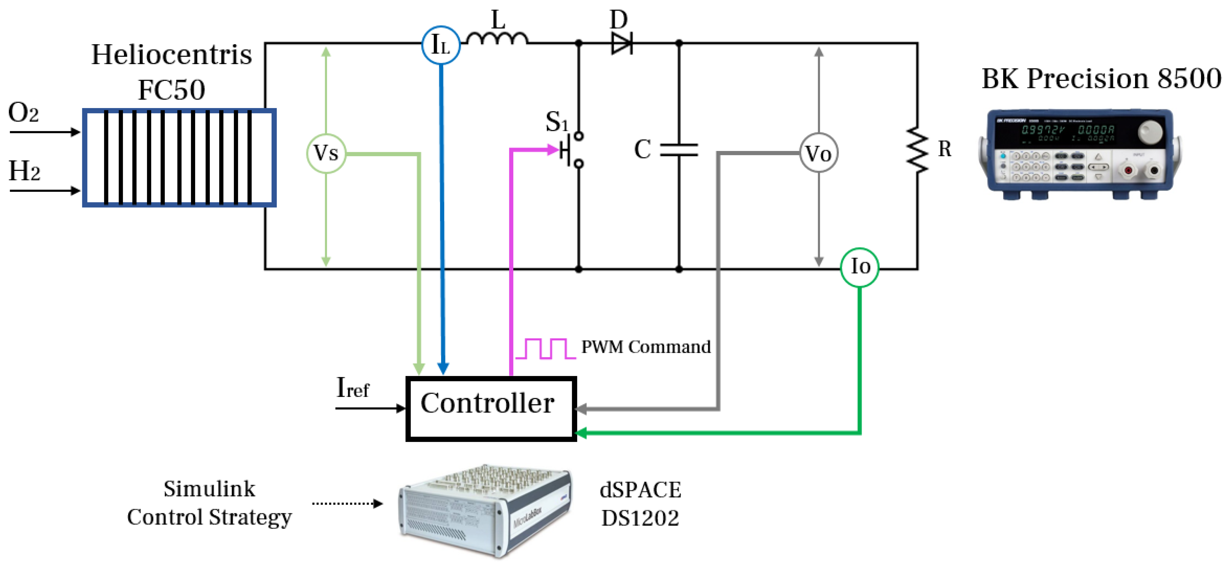
2.1. Employed Hardware
2.2. Control Design
2.3. Fuzzy Logic Control
- Case 1 (red cells from Table 2): . In this situation, the duty cycle increment is positive. Equation (3) shows that an increment of d will decrease . As and according to Figure 2, the resistance is reduced when the current increases. This means to move to the right of curve showed in the mentioned graph. Therefore, it can be concluded that and E will have positive values. Thus, Equation (6) will be negative.
- Case 2 (green cell from Table 2): . For this case, it is assumed that is negative while E is positive. Nevertheless, a positive increment of the duty cycle will cause the same action as in Case 1 where yields to a positive, which is the same sign as E. Consequently, .
- Case 3 (orange cell from Table 2): . In this instance, the control action is null which implies that there is no change. Thus, since the derivative of the normalised error is positive while the error is negative, it can be concluded that . This reasoning can be used as well in the table diagonal since it will drive to the same conclusion.
2.4. Sliding Mode Control
3. Experimental Results
4. Conclusions
Author Contributions
Funding
Institutional Review Board Statement
Informed Consent Statement
Acknowledgments
Conflicts of Interest
Abbreviations
| PEMFC | Proton exchange membrane fuel cells |
| FCEV | Fuel cell electric vehicles |
| LCSFC | Large capacity stationary fuel cells |
| LQR | Linear quadratic regulator |
| LPV | Linear parameter varying |
| PID | Proportional-integral-derivative |
| SMC | Sliding mode control |
| MPPT | Maximum power point tracking |
| FLC | Fuzzy logic control |
| SEPIC | Single ended primary-inductor converter |
| MOSFET | Metal-oxide-semiconductor-field-effect transistor |
| PWM | Pulse-width-modulation |
| FPGA | Field-programmable gate array |
| RTI | Real-time interface |
References
- Hasan, A.; McCormack, S.J.; Huang, M.J.; Norton, B. Energy and Cost Saving of a Photovoltaic-Phase Change Materials (PV-PCM) System through Temperature Regulation and Performance Enhancement of Photovoltaics. Energies 2014, 7, 1318–1331. [Google Scholar] [CrossRef] [Green Version]
- Mahapatra, M.K.; Singh, P. Chapter 24-Fuel Cells: Energy Conversion Technology. In Future Energy, 2nd ed.; Letcher, T.M., Ed.; Elsevier: Boston, MA, USA, 2014; pp. 511–547. [Google Scholar] [CrossRef]
- Andújar, J.; Segura, F. Fuel cells: History and updating. A walk along two centuries. Renew. Sustain. Energy Rev. 2009, 13, 2309–2322. [Google Scholar] [CrossRef]
- Ho, J.; Saw, E.C.; Lu, L.; Liu, J. Technological barriers and research trends in fuel cell technologies: A citation network analysis. Technol. Forecast. Soc. Chang. 2014, 82, 66–79. [Google Scholar] [CrossRef]
- Weidner, E.; Cebolla, R.O.; Davies, J. Global deployment of large capacity stationary fuel cells. In JRC Technical Reports; Joint Research Centre: Ispra, Italy, 2019. [Google Scholar] [CrossRef]
- Yonoff, R.E.; Ochoa, G.V.; Cardenas-Escorcia, Y.; Silva-Ortega, J.I.; Meriño-Stand, L. Research trends in proton exchange membrane fuel cells during 2008–2018: A bibliometric analysis. Heliyon 2019, 5, e01724. [Google Scholar] [CrossRef] [PubMed] [Green Version]
- Louzazni, M.; Al-Dahidi, S.; Mussetta, M. Fuel Cell Characteristic Curve Approximation Using the Bézier Curve Technique. Sustainability 2020, 12, 8127. [Google Scholar] [CrossRef]
- Mayyas, A.; Mann, M. Emerging Manufacturing Technologies for Fuel Cells and Electrolyzers. Procedia Manuf. 2019, 33, 508–515. [Google Scholar] [CrossRef]
- Abdelkareem, M.A.; Elsaid, K.; Wilberforce, T.; Kamil, M.; Sayed, E.T.; Olabi, A. Environmental aspects of fuel cells: A review. Sci. Total Environ. 2021, 752, 141803. [Google Scholar] [CrossRef] [PubMed]
- Belhaj, F.Z.; El Fadil, H.; Idrissi, Z.E.; Koundi, M.; Gaouzi, K. Modeling, Analysis and Experimental Validation of the Fuel Cell Association with DC-DC Power Converters with Robust and Anti-Windup PID Controller Design. Electronics 2020, 9, 1889. [Google Scholar] [CrossRef]
- Kodra, K.; Zhong, N. Singularly Perturbed Modeling and LQR Controller Design for a Fuel Cell System. Energies 2020, 13, 2735. [Google Scholar] [CrossRef]
- Chen, F.X.; Jiao, J.R.; Liu, S.G.; Yu, Y.; Xu, S.C. Control-oriented LPV Modeling for the Air Supply System of Proton Exchange Membrane Fuel Cells. Fuel Cells 2018, 18, 433–440. [Google Scholar] [CrossRef]
- Rosli, R.; Majlan, E.H.; Wan Daud, W.; Hamid, S. Hydrogen rate manipulation of proton exchange membrane fuel cell (PEMFC) stack using feedback control system. In Proceedings of the 2012 IEEE International Conference on Power and Energy (PECon), Kota Kinabalu, Malaysia, 2–5 December 2012; pp. 553–557. [Google Scholar] [CrossRef]
- Cruz Rojas, A.; Lopez Lopez, G.; Gomez-Aguilar, J.F.; Alvarado, V.M.; Sandoval Torres, C.L. Control of the Air Supply Subsystem in a PEMFC with Balance of Plant Simulation. Sustainability 2017, 9, 73. [Google Scholar] [CrossRef] [Green Version]
- Wang, M.; Tang, F.; Wu, X.; Niu, J.; Zhang, Y.; Wang, J. A Nonlinear Control Strategy for DC-DC Converter with Unknown Constant Power Load Using Damping and Interconnection Injecting. Energies 2021, 14, 3031. [Google Scholar] [CrossRef]
- Awais, M.; Khan, L.; Ahmad, S.; Jamil, M. Feedback-Linearization-Based Fuel-Cell Adaptive-Control Paradigm in a Microgrid Using a Wavelet-Entrenched NeuroFuzzy Framework. Energies 2021, 14, 1850. [Google Scholar] [CrossRef]
- Chen, Y.T.; Yu, C.S.; Chen, P.N. Feedback Linearization Based Robust Control for Linear Permanent Magnet Synchronous Motors. Energies 2020, 13, 5242. [Google Scholar] [CrossRef]
- Li, T.; Liu, X. Model-Free Non-Cascade Integral Sliding Mode Control of Permanent Magnet Synchronous Motor Drive with a Fast Reaching Law. Symmetry 2021, 13, 1680. [Google Scholar] [CrossRef]
- Bjaoui, M.; Khiari, B.; Benadli, R.; Memni, M.; Sellami, A. Practical Implementation of the Backstepping Sliding Mode Controller MPPT for a PV-Storage Application. Energies 2019, 12, 3539. [Google Scholar] [CrossRef] [Green Version]
- Valderrama-Blavi, H.; Rodríguez-Ramos, E.; Olalla, C.; Genaro-Muñoz, X. Sliding-Mode Approaches to Control a Microinverter Based on a Quadratic Boost Converter. Energies 2019, 12, 3697. [Google Scholar] [CrossRef] [Green Version]
- Wang, B.; Jahanshahi, H.; Volos, C.; Bekiros, S.; Yusuf, A.; Agarwal, P.; Aly, A.A. Control of a Symmetric Chaotic Supply Chain System Using a New Fixed-Time Super-Twisting Sliding Mode Technique Subject to Control Input Limitations. Symmetry 2021, 13, 1257. [Google Scholar] [CrossRef]
- Napole, C.; Derbeli, M.; Barambones, O. A global integral terminal sliding mode control based on a novel reaching law for a proton exchange membrane fuel cell system. Appl. Energy 2021, 301, 117473. [Google Scholar] [CrossRef]
- Muthugala, M.A.V.J.; Vega-Heredia, M.; Mohan, R.E.; Vishaal, S.R. Design and Control of a Wall Cleaning Robot with Adhesion-Awareness. Symmetry 2020, 12, 122. [Google Scholar] [CrossRef] [Green Version]
- Khairuddin, S.H.; Hasan, M.H.; Hashmani, M.A.; Azam, M.H. Generating Clustering-Based Interval Fuzzy Type-2 Triangular and Trapezoidal Membership Functions: A Structured Literature Review. Symmetry 2021, 13, 239. [Google Scholar] [CrossRef]
- Viswanathan, K.; Oruganti, R.; Srinivasan, D. Non-linear function controller: A simple alternative to fuzzy logic controller for a power electronic converter. In Proceedings of the 30th Annual Conference of IEEE Industrial Electronics Society, 2004, IECON 2004, Busan, Korea, 2–6 November 2004; Volume 3, pp. 2655–2660. [Google Scholar] [CrossRef]
- Khan, W.A.; Ali, B.; Taouti, A. Bipolar Picture Fuzzy Graphs with Application. Symmetry 2021, 13, 1427. [Google Scholar] [CrossRef]
- Parimala, M.; Jafari, S.; Riaz, M.; Aslam, M. Applying the Dijkstra Algorithm to Solve a Linear Diophantine Fuzzy Environment. Symmetry 2021, 13, 1616. [Google Scholar] [CrossRef]
- Liu, D.; Huang, A.; Liu, Y.; Liu, Z. An Extension TOPSIS Method Based on the Decision Maker’s Risk Attitude and the Adjusted Probabilistic Fuzzy Set. Symmetry 2021, 13, 891. [Google Scholar] [CrossRef]
- Georgieva, A.; Pavlova, A. Fuzzy Sawi Decomposition Method for Solving Nonlinear Partial Fuzzy Differential Equations. Symmetry 2021, 13, 1580. [Google Scholar] [CrossRef]
- Pedraza, T.; Ramos-Canós, J.; Rodríguez-López, J. Aggregation of Weak Fuzzy Norms. Symmetry 2021, 13, 1908. [Google Scholar] [CrossRef]
- Ramalu, T.; Mohd Radzi, M.A.; Mohd Zainuri, M.A.A.; Abdul Wahab, N.I.; Abdul Rahman, R.Z. A Photovoltaic-Based SEPIC Converter with Dual-Fuzzy Maximum Power Point Tracking for Optimal Buck and Boost Operations. Energies 2016, 9, 604. [Google Scholar] [CrossRef]
- Harrag, A.; Messalti, S. How fuzzy logic can improve PEM fuel cell MPPT performances? Int. J. Hydrog. Energy 2018, 43, 537–550. [Google Scholar] [CrossRef]
- Derbeli, M.; Barambones, O.; Silaa, M.Y.; Napole, C. Real-Time Implementation of a New MPPT Control Method for a DC-DC Boost Converter Used in a PEM Fuel Cell Power System. Actuators 2020, 9, 105. [Google Scholar] [CrossRef]
- Farhat, M.; Barambones, O.; Sbita, L. Efficiency optimization of a DSP-based standalone PV system using a stable single input fuzzy logic controller. Renew. Sustain. Energy Rev. 2015, 49, 907–920. [Google Scholar] [CrossRef]
- Urrea, C.; Jara, D. Design, Analysis, and Comparison of Control Strategies for an Industrial Robotic Arm Driven by a Multi-Level Inverter. Symmetry 2021, 13, 86. [Google Scholar] [CrossRef]
- Azam, M.H.; Hasan, M.H.; Hassan, S.; Abdulkadir, S.J. A Novel Approach to Generate Type-1 Fuzzy Triangular and Trapezoidal Membership Functions to Improve the Classification Accuracy. Symmetry 2021, 13, 1932. [Google Scholar] [CrossRef]
- Napole, C.; Derbeli, M.; Barambones, O. Fuzzy Logic Approach for Maximum Power Point Tracking Implemented in a Real Time Photovoltaic System. Appl. Sci. 2021, 11, 5927. [Google Scholar] [CrossRef]
- Sałabun, W.; Shekhovtsov, A.; Pamučar, D.; Wątróbski, J.; Kizielewicz, B.; Więckowski, J.; Bozanić, D.; Urbaniak, K.; Nyczaj, B. A Fuzzy Inference System for Players Evaluation in Multi-Player Sports: The Football Study Case. Symmetry 2020, 12, 2029. [Google Scholar] [CrossRef]
- Sangeetha, V.; Krishankumar, R.; Ravichandran, K.S.; Cavallaro, F.; Kar, S.; Pamucar, D.; Mardani, A. A Fuzzy Gain-Based Dynamic Ant Colony Optimization for Path Planning in Dynamic Environments. Symmetry 2021, 13, 280. [Google Scholar] [CrossRef]
- Wen, X.; Zhang, X.; Lei, T. Intuitionistic Fuzzy (IF) Overlap Functions and IF-Rough Sets with Applications. Symmetry 2021, 13, 1494. [Google Scholar] [CrossRef]
- Napole, C.; Barambones, O.; Calvo, I.; Derbeli, M.; Silaa, M.Y.; Velasco, J. Advances in Tracking Control for Piezoelectric Actuators Using Fuzzy Logic and Hammerstein-Wiener Compensation. Mathematics 2020, 8, 2071. [Google Scholar] [CrossRef]
- Hong, Q.; Shi, Y.; Chen, Z. Adaptive Sliding Mode Control Based on Disturbance Observer for Placement Pressure Control System. Symmetry 2020, 12, 1057. [Google Scholar] [CrossRef]
- Zenteno-Torres, J.; Cieslak, J.; Dávila, J.; Henry, D. Sliding Mode Control with Application to Fault-Tolerant Control: Assessment and Open Problems. Automation 2021, 2, 1–30. [Google Scholar] [CrossRef]
- Lin, C.H.; Hsiao, F.Y. Proportional-Integral Sliding Mode Control with an Application in the Balance Control of a Two-Wheel Vehicle System. Appl. Sci. 2020, 10, 5087. [Google Scholar] [CrossRef]
- Munteanu, L.; Dumitriu, D.; Brisan, C.; Bara, M.; Chiroiu, V.; Nedelcu, N.; Rugina, C. Sliding Mode Control and Geometrization Conjecture in Seismic Response. Symmetry 2021, 13, 353. [Google Scholar] [CrossRef]
- Kalman, R.E.; Bertram, J.E. Control system analysis and design via the “second method” of Lyapunov: I—Continuous-time systems. J. Basic Eng. 1960, 82, 371–393. [Google Scholar] [CrossRef]
- LaSalle, J.; Lefschetz, S. Stability by Lyapunov’s Second Method with Applications; Academic Press: New York, NY, USA, 1961; Volume 5, pp. 371–393. [Google Scholar]


| Heliocentris PEMFC FC50 | Values | Units |
|---|---|---|
| Operating voltage | 2.5–9 | VDC |
| Operating current | 0–10 | A |
| Rated output power | 40 | W |
| Open-circuit voltage | 9 | VDC |
| Boost converter TEP192 | ||
| Inductance | 6 | H |
| Input capacitor | 1500 | F |
| Output capacitor | 3000 | F |
| Max. input voltage | 60 | V |
| Max. input current | 30 | A |
| Max. output voltage | 250 | V |
| Max. output current | 30 | A |
| E\ | NB | NS | Z | PS | PB |
|---|---|---|---|---|---|
| NB | NB | NM | NM | NS | Z |
| NS | NM | NM | NS | Z | Z |
| Z | NM | NS | Z | PS | PM |
| PS | Z | Z | PS | PM | PM |
| PB | Z | PS | PM | PM | PB |
| Current (A) | Voltage (V) | Power (W) | ||||
|---|---|---|---|---|---|---|
| SMC | FLC | SMC | FLC | SMC | FLC | |
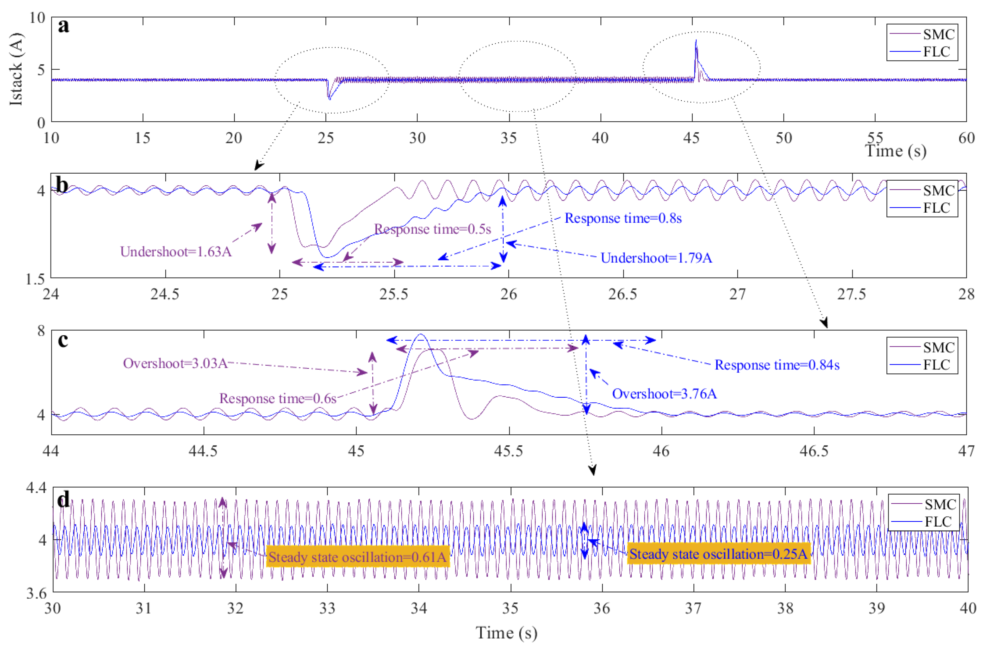
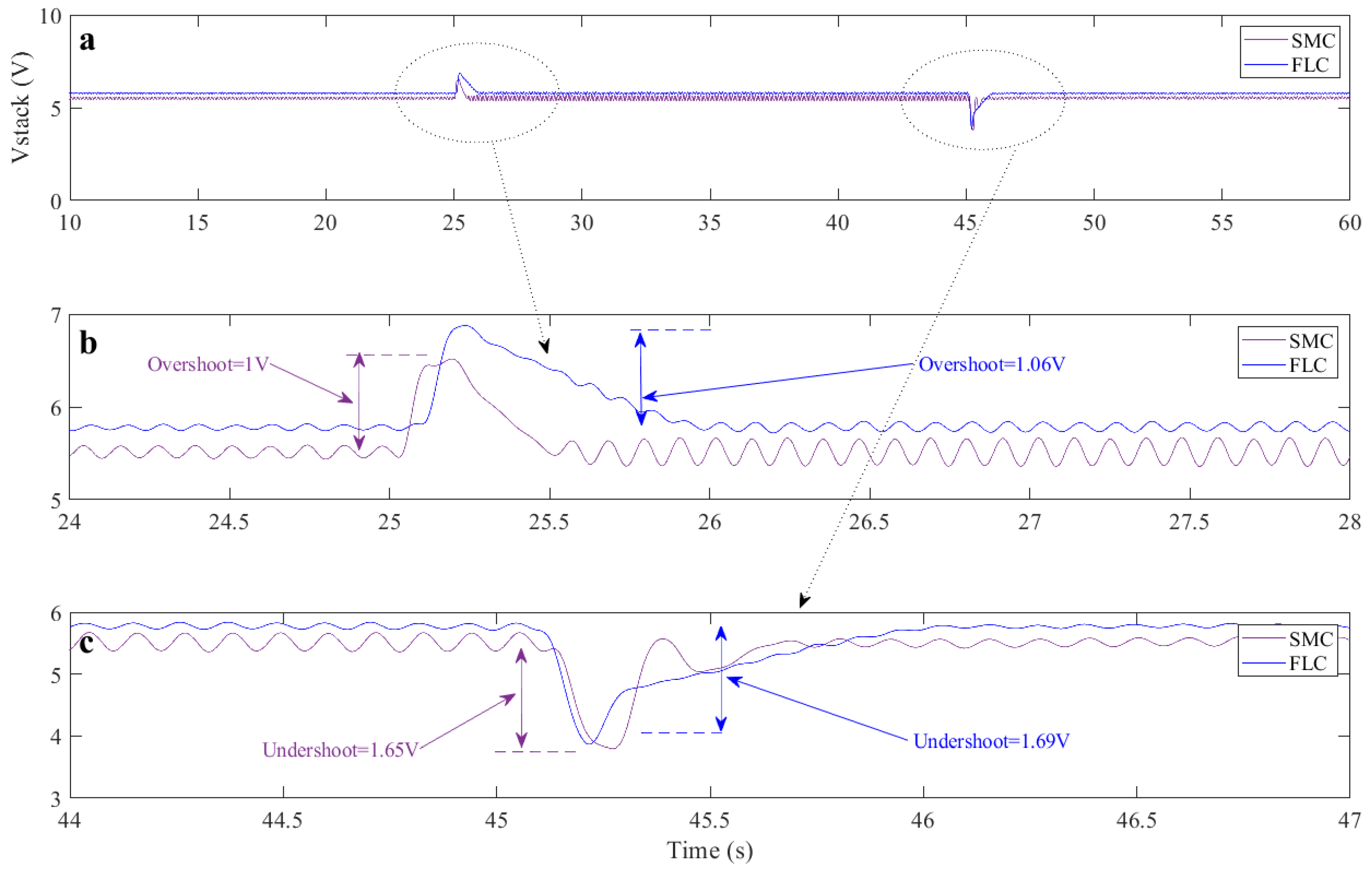
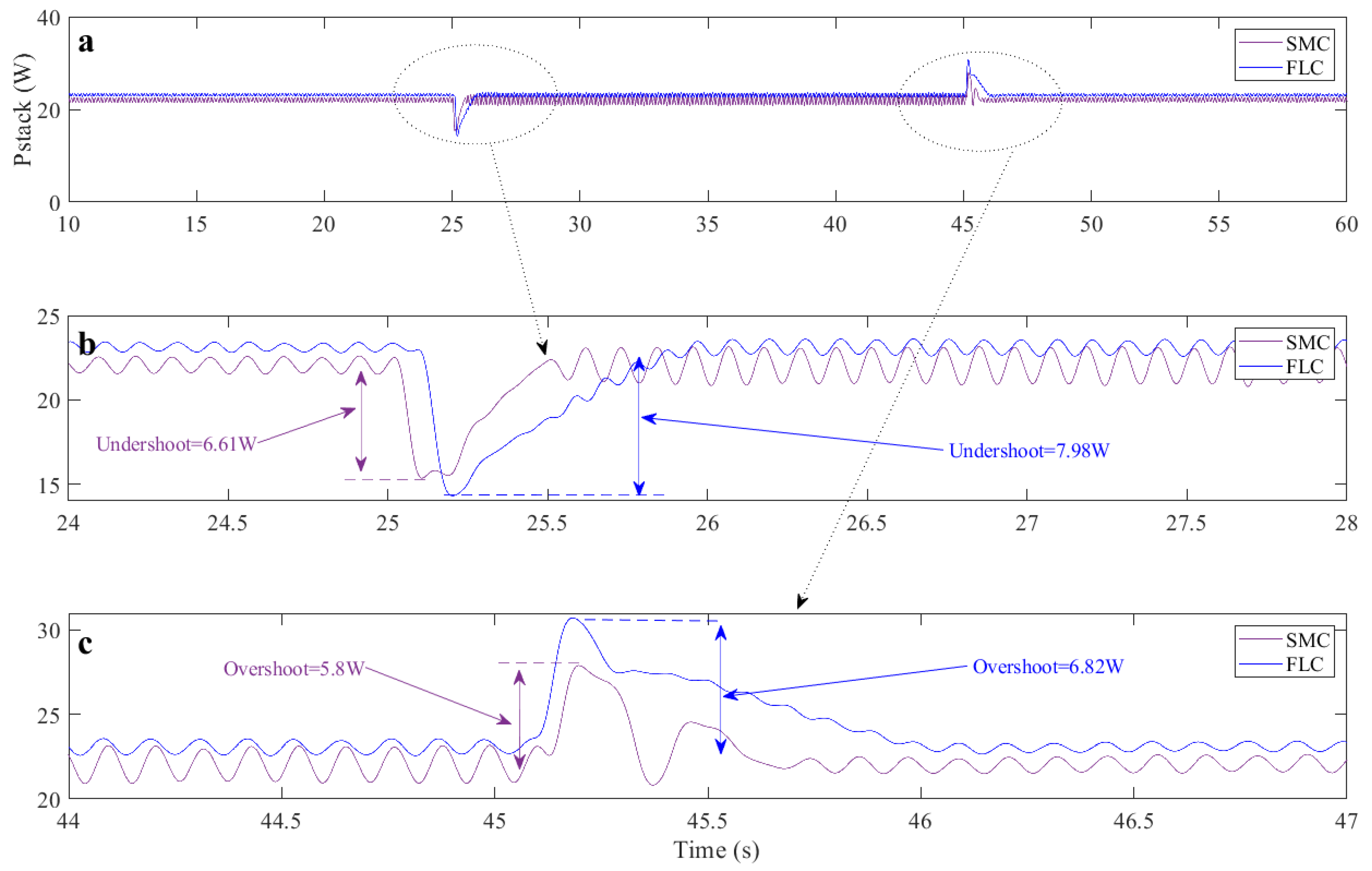
| Overshoot | 3.03 | 3.76 | 1 | 1.06 | 5.8 | 6.82 |
| Undershoot | 1.63 | 1.79 | 1.65 | 1.69 | 6.61 | 7.98 |
| Response Time | 0.5 | 0.8 | 0.5 | 0.8 | 0.5 | 0.8 |
| Oscillation | 0.61 | 0.25 | 0.33 | 0.14 | 2.2 | 0.9 |
Publisher’s Note: MDPI stays neutral with regard to jurisdictional claims in published maps and institutional affiliations. |
© 2022 by the authors. Licensee MDPI, Basel, Switzerland. This article is an open access article distributed under the terms and conditions of the Creative Commons Attribution (CC BY) license (https://creativecommons.org/licenses/by/4.0/).
Share and Cite
Napole, C.; Derbeli, M.; Barambones, O. Experimental Analysis of a Fuzzy Scheme against a Robust Controller for a Proton Exchange Membrane Fuel Cell System. Symmetry 2022, 14, 139. https://doi.org/10.3390/sym14010139
Napole C, Derbeli M, Barambones O. Experimental Analysis of a Fuzzy Scheme against a Robust Controller for a Proton Exchange Membrane Fuel Cell System. Symmetry. 2022; 14(1):139. https://doi.org/10.3390/sym14010139
Chicago/Turabian StyleNapole, Cristian, Mohamed Derbeli, and Oscar Barambones. 2022. "Experimental Analysis of a Fuzzy Scheme against a Robust Controller for a Proton Exchange Membrane Fuel Cell System" Symmetry 14, no. 1: 139. https://doi.org/10.3390/sym14010139
APA StyleNapole, C., Derbeli, M., & Barambones, O. (2022). Experimental Analysis of a Fuzzy Scheme against a Robust Controller for a Proton Exchange Membrane Fuel Cell System. Symmetry, 14(1), 139. https://doi.org/10.3390/sym14010139