Article

FPGA Realization of the Parameter-Switching Method in the Chen Oscillator and Application in Image Transmission

by
Vincent-Ademola Adeyemi
1,†,
Jose-Cruz Nuñez-Perez
1,*,†,
Yuma Sandoval Ibarra
2,†,
Francisco-Javier Perez-Pinal
3,† and
Esteban Tlelo-Cuautle
4,†
1
Instituto Politécnico Nacional, IPN-CITEDI, Tijuana 22435, Mexico
2
Departamento de Posgrado, Universidad Politécnica de Lázaro Cárdenas (UPLC), Lázaro Cárdenas 60950, Mexico
3
Tecnológico Nacional de México, Instituto Tecnológico de Celaya, Celaya 38010, Mexico
4
Instituto Nacional de Astrofísica, Óptica y Electrónica, INAOE, San Andres Cholula 72840, Mexico
*
Author to whom correspondence should be addressed.
These authors contributed equally to this work.
Symmetry 2021, 13(6), 923; https://doi.org/10.3390/sym13060923
Submission received: 9 April 2021 / Revised: 3 May 2021 / Accepted: 17 May 2021 / Published: 22 May 2021
(This article belongs to the Special Issue Symmetry in Chaotic Systems and Circuits Ⅱ)

Abstract

:
In this paper, the parameter-switching technique was applied to control chaos in the Chen oscillator and as a decryption mechanism in a secure transmission system, to transmit RGB and grayscale images. In the past few decades, considerable efforts have been put into the study of the stabilization of chaotic dynamical systems. Most of the well-known chaos control methods, such as Ott, Grebogi, and Yorke (OGY), Pyragas, and open-loop methods, force an unstable periodic orbit into a stable one while distorting the original attractor. On the other hand, the parameter-switching technique is an elegant method that can synthesize an already-existing stable orbit, thereby preserving the underlying attractor. Consequently, the main contributions of this work were the FPGA realizations of the parameter-switching method and a secure image transmission system using a synchronized master and slave topology. The results of the parameter-switching technique and synchronization were verified using phase plots and time series. The chaos-encrypted image from the image transmission system, verified using correlation, showed no relativity with the original image, while the recovery of the decrypted image has no loss of quality. The encryption and decryption system was symmetric, whereby the key was private. In this work, co-simulations were performed in Active-HDL with MATLAB/Simulink, while the target FPGA board was the Xilinx’s Artix-7 AC701.

1. Introduction

The concept and qualitative theory of dynamical systems was originated by a French mathematician, Henri Poincaré. The methods he developed prepared the foundation for the analysis of a nonlinear system of differential equations. Generally, in a nonlinear system, the time evolution of the states is controlled by laws that are dependent on the values of the state variables in a way that does not accomplish proportionality [1]. A nonlinear system consists of a state space, whose coordinates describe the state at any instant. To determine the state of a dynamical system in the long term, the system must be iterated several times, advancing in each iteration with a small step size. Starting with an initial point, the entire future positions of a nonlinear system can be known, provided the system has a solution. The future positions are collectively called a trajectory [2,3,4,5].
The characteristics of a nonlinear system can be verified by evaluating the bifurcation diagram, nonlinear divergence, multistability, fractal dimension, and limit cycle [6,7]. Bifurcation is defined as the change in the dynamical behavior of a nonlinear system while varying a parameter of the system. Nonlinear divergence occurs when the associated linear components of certain state variables are totally stable if the states approach infinity. Multistability is a nonlinear behavior defining the occurrence of more than two stable states. The fractal characteristic is seen when the system shows self-similarity in the phase space geometric pattern, whereby the pattern is reproduced at smaller sizes to generate surfaces and irregular shapes, which is impossible to show by conventional geometry. The limit cycle is a behavior whereby the nonlinear dynamical system possesses a significant periodic orbit. Lastly, an irregular and chaotic behavior occurs when the system displays sensitivity to the initial value.
The intrinsic behavior of nonlinear dynamical systems after a long time when illustrated by the phase space diagram is dependent on the basin of attraction [8,9,10,11]. The basin of attraction is simply the various initial conditions that give a dynamical system a particular qualitative state in the long term. Such qualitative behavior, in terms of the attractor, includes chaotic, periodic, or quasi-periodic. This, by implication, means that there exist in a nonlinear dynamical system different basins of attraction. Moreover, the inherent nonlinearity in the coupled system as a factor for the system instability cannot be overemphasized. The tuning of nonlinearities to enhance the dynamical behavior of the system, otherwise called functionalization, was studied in [12,13]. It has been shown that many physical phenomena are intrinsically nonlinear in nature. For instance, nonlinear models govern physical phenomena such as fluid and plasma mechanics, elasticity, aircraft and spacecraft control, gravitational and electrostatic attraction, gas dynamics, robotics, biological systems, bio-mechanics, combustion, and chemical reactions. The chaotic behavior of a nonlinear dynamical system is a basic property that encounters a huge number of applications in engineering. Specifically, nonlinear systems are fundamental to the concept of chaos theory, and deterministic and discrete chaotic dynamical systems are having many interventions in engineering and science [14,15,16,17,18,19].
As a parameter of a dynamical system is varied, chaos is generated from an infinite series of period-doubling bifurcations of periodic orbits. This is called the period doubling to chaos [20]. Chaotic attractors usually have closely-packed unstable periodic orbits (UPOs) embedded in them. In the past few years, considerable efforts, both theoretical and experimental, have been devoted to how to stabilize chaotic dynamical systems, whereby the orbits change a little under small perturbations of a parameter. This is otherwise called chaos control. Three famous chaos control techniques are the Ott, Grebogi, and Yorke (OGY) method, the Pyragas method, and the open-loop control method. The OGY is a discontinuous feedback control method, which works by first selecting an UPO from the chaotic system and, then, an appropriate parameter giving a small, wisely chosen perturbation once per cycle to keep the system on the selected orbit, while shifting and distorting the chaotic attractor to reach the stabilization of the general UPOs [21,22,23]. The Pyragas method is a feedback control technique, which applies an appropriate continuous control signal to the system through a feedback function [24,25,26]. In the case of the open-loop method, otherwise called the feed-forward method, a properly chosen external harmonic excitation is applied to the system to ensure the convergence of the trajectories to the desired periodic orbit [27,28]. Alternatively, a notable technique that is being used in controlling chaos in dynamical systems is the parameter-switching method [29,30,31]. Compared with the traditional chaos control techniques mentioned above, in which an UPO is forced into a stable periodic orbit, the parameter-switching method synthesizes an already existing stable orbit while preserving the underlying chaotic attractor.
Experimental verifications of chaotic systems through electronic implementations led us to create real applications based on chaos, such as: secure communication systems and cryptography. The field-programmable gate array (FPGA) is a viable option for digitally implementing chaotic systems. They have become a very dependable choice for the electronic implementation of chaotic systems because they can be reprogrammed, making the FPGAs reusable, adaptable, and extremely cost effective; hence, they have become the preferred option for the purpose of fast prototyping. Furthermore, FPGAs perform parallel processing at a higher speed. Moreover, designing FPGAs using hardware description languages (HDLs) is done very quickly and efficiently.
Much work have been done on the implementation of chaotic systems on FPGAs. For example: The authors in [32] showed a chaotic oscillator that was spherical in shape, realized on the Artix-7 AC701 and Stratix III boards for transmission of RGB and grayscale images. The numerical solution was obtained by applying the fifth Runge–Kutta method. Both their MATLAB and VHDL simulations were in good agreement. In [33], a Lü–Chen chaotic system was developed in VHDL with the Heun algorithm, implemented on a Virtex-6 board, and the outputs confirmed the results obtained from MATLAB. Furthermore, the work in [34] showed a 3D chaotic system realized on an FPGA DE2-115 Altera board, using the Euler algorithm. The work included an application for encrypting an image with chaos. In [35], a novel chaotic TRNG that was based on an ANN was implemented on a Virtex-6 board. In this work, the numerical method for the underlying chaotic oscillator was the fifth Runge–Kutta. A coupled map lattice, capable of displaying very complex spatio-temporal chaotic behavior, was used in [36] to create a cryptosystem and implemented on a Spartan-3 board. The article [37] considered the realization of a novel chaotic system, having one parameter, on a Cyclone IV board using forward Euler to find the solution. The investigation also included a secure communication system realized on the FPGA board. Other recent related works on the FPGA implementation of secure communication systems based on chaos can be found in [38,39,40,41,42,43,44].
In addition to the FPGA implementations discussed above, there are numerous numerical implementations of image security systems as seen in [45,46,47,48]. In the work presented in [45], a new image encryption system was proposed, based on a hyperchaotic oscillator, cellular automata, and particle swarm optimization. The authors in [46] presented a novel single-dimensional chaotic system and applied it to secure grayscale and RGB images. In the encryption process, bits were first shifted dynamically, and then, a diffusion method was applied to complete the image encryption. The work in [47] also applied a plain image to generate the keys to control the method of image encryption and compression, based on compressive sensing. The permutation and diffusion were performed by a 2D sine logistic iterative chaotic map and a 2D logistic sine coupling map. Finally, a novel approach was proposed in [48] to improve the cryptographic characteristics of substitution boxes, with the Choquet fuzzy integral and DNA methods as the backbone. The image encryption was performed using the DNA-coded fuzzy-based S-boxes and a Chen hyperchaotic map’s chaotic sequence encoded by DNA. The numerical implementations of these works were performed in MATLAB.
In this work, the authors investigated the application of the parameter-switching technique in approximating the stable dynamics of the Chen oscillator and its usefulness in a chaos-based image transmission system, with a view of a digital implementation on an FPGA device. The encryption and decryption system embedded in the transmission system was based on the symmetric cryptographic concept in which the key was kept private. In light of the foregoing aim of this work, the following contributions to the state-of-the-art are hereby highlighted:
(i)
FPGA realization of the parameter-switching scheme to approximate the stable cycles of the Chen oscillator, using VHDL as the implementation language with a word length of 24 bits, on the Xilinx’s Artix-7 AC701 board. The VHDL implementation on the FPGA board agreed completely with the numerical simulations done in MATLAB;
(ii)
FPGA realization of a secure chaos-based image transmission system on the Xilinx’s Artix-7 AC701 board, using VHDL with a 24 bit word length, whereby the parameter-switching scheme was applied as a decryption mechanism to recover chaos-encrypted RGB and grayscale images. The backbone of the secure image transmission system was a synchronized master and slave Chen system, in which the state observer was the slave system that approximated the master system. The VHDL implementation and MATLAB numerical simulations of the image transmission were in complete agreement.
In the subsequent parts of this paper, Section 2 introduces the mathematical model of the Chen oscillator, the parameter-switching technique applied in obtaining the stable cycles of the Chen oscillator, and the synchronization method. Section 3 presents the results of the synthesis of stable attractors by the parameter-switching scheme and synchronizing two Chen oscillators in a master and slave configuration. Section 4 details the secure image transmission system, with the application of the parameter-switching scheme for decrypting chaos-encrypted RGB and grayscale images. Section 5 contains the discussion of the results obtained in this work. Lastly, the conclusion is presented in Section 6.

2. Theoretical Framework

The Chen oscillator is one of the popular chaotic systems that has been widely researched in the past few years [49,50,51,52]. It is comprised of the following coupled system of ordinary differential equations of the first-order:
d x d t = a ( y x ) d y d t = ( c a ) x x z + c y d z d t = x y b z
where x, y, and z are the system-dependent variables. Traditionally, the Chen oscillator is chaotic when a = 35, b = 3, and c = 28. The oscillator is dissipative when a + b > c and possesses the following three equilibrium points [49]: EP 0 = ( 0 , 0 , 0 ) , EP 1 = ( b ( 2 c a ) , b ( 2 c a ) , 2 c a ) , and EP 2 = ( b ( 2 c a ) , b ( 2 c a ) , 2 c a ) . At EP 0 , the eigenvalues are λ 1 = –3, λ 2 = –30.8359, and λ 3 = 23.8359. EP 1 and EP 2 have the same eigenvalues, which are λ 1 = –18.4280, λ 2 = 4.2140 + 14.8846i, and λ 3 = 4.2140 − 14.8846i.

2.1. Parameter-Switching Method

The parameter switching (PS) is an elegant method for approximating numerically any desired solution of a continuous nonlinear and autonomous integer or fractional-order dynamical system modeled by a general initial value problem (IVP) [29,30,53,54,55]. It involves selecting a limited number of parameter values in which the control parameter p within the chosen set is switched in some periodic (deterministic) manner for relatively short time sub-intervals i j , while numerically integrating the underlying IVP. At the end, the solution obtained from the “switched” system in the PS scheme will converge to the “averaged” solution when p is changed to p * , which is the average of the values that are switched. The next general IVP describes many dynamical systems, the Chen system in Equation (1) inclusive:
d x d t = f ( x ( t ) ) + p A x ( t ) , x ( 0 ) = x 0 , t I = [ 0 , T ]
where f: R n R n is a Lipschitz continuous nonlinear function, pR is the switched parameter, x 0 R n represents the initial value, T > 0, and AL(R n ) is a constant matrix. Modeling the Chen system in Equation (1) after the IVP in Equation (2) with parameter c = p as the control parameter and giving a and b their conventional values, then:
f ( x ) = a ( y x ) a x x z x y b z
and:
A = 0 0 0 1 0 0 0 0 0
The PS is expressed in the scheme that follows:
[ m 1 p 1 , m 2 p 2 , , m N p N ]
where p k are the control parameters, i.e., p in the general IVP above, m k represents the weights associated with each p j , and N (N > 1) represents the total number of switched parameters. When the IVP is being integrated, starting with m 1 integration steps, then p = p 1 . In the following m 2 sub-interval, p = p 2 . The integration continues in this manner until the final m N sub-interval, whereby p = p N . Following the same procedure, the PS algorithm repeats again until the integration time interval I is covered. Mathematically, sub-interval i k = m k h. Figure 1 gives the illustration of the PS scheme.
The “averaged” solution of p*, to which the PS solution converges, is denoted by:
p * = k = 1 N m k p k k = 1 N m k
Notation 1. 
Let A be the set of attractors depending on parameter p, P be the set of all possible p values, and M be the set of all possible weights m.
Notation 2. 
P N = { p 1 , p 2 , , p N } P denotes the set of chosen p. M N = { m 1 , m 2 , , m N } M is the set of chosen m. A N = { A p 1 , A p 2 , , A p N } A is the set of the underlying attractors corresponding to P N .
Notation 3. 
A S represents the attractor obtained from the “switched” solution using the PS scheme, and A* is the attractor of the “averaged” solution when p = p*.
If the PS scheme in (5) is applied to any system represented by the initial value problem in Equation (2), like the Chen model, it is possible to approximate any desired attractor of the system by simply switching the control parameter. For example, to approximate a stable orbit of a dynamical system, the set P N is chosen from the chaotic window of the system, while p* corresponds to a periodic window. Hence, between the chaotic windows, there exists at least one periodic window. It is important to note that the PS scheme does not change the original properties of attractor A S .
Remark 1. 
The uniqueness of having different p values gives the possibility of getting different solutions.
Remark 2. 
In the practical sense, it is very much feasible to approximate an attractor A* from within a set P N , which does not contain p*, i.e., p* ∉ P N , but p* is within the real open interval ( p 1 , p N ) because p* is a convex combination of ordered p k , where k = 1, 2, …, N.
Remark 3. 
The same attractor A S can be obtained with different choices of P N and M N .
A four-step methodology for the synthesis of attractors by parameter switching is adopted as follows:
Step 1: Select the appropriate switched parameters for the switching scheme and their associated weights.
Step 2: Execute the parameter-switching scheme using the model in Equation (2) to generate the synthesized attractor A S of the “switched” solution.
Step 3: Replace p in model (2) with p*, and run to generate attractor A* of the “averaged” solution.
Step 4: Show that the attractor A S of the “switched” solution matches A* of the “averaged” solution.
Remark 4. 
Without loss of generality, the initial condition x 0 for the “switched” solution and y 0 for the “averaged” solution are the same ( x 0 = y 0 ), in order to reduce the transient steps.

2.2. Synchronization of Two Chen Oscillators

Hamiltonian systems with the observer-based approach are employed in this section to synchronize two chaotic Chen oscillators in Equation (1), in a master–slave configuration. The slave unit served as the state observer, which approximates the master unit. A detailed description of the Hamiltonian systems with the observer-based approach is contained in [56]. The following is the mathematical representation of the master and slave units in the Hamiltonian system:
Let d x d t = f ( x ) be a dynamical system, in which xR n represents the state variable and f: R n R n is the nonlinear function. The Hamiltonian forms can be described as:
d x d t = J ( x ) H x + S ( x ) H x + F ( x ) , x R n
whereby H ( x ) = 1 2 x T M x is the energy function greater than zero belonging to R n , in which M is a definite matrix greater than zero, constant and symmetric. Therefore, H x = M x . Furthermore, H x is the gradient vector derived from H ( x ) . Matrix J ( x ) fulfills J ( x ) + J T ( x ) = 0 , while S ( x ) satisfies S ( x ) = S T ( x ) for all x R n . The vector field J ( x ) H x is the conservative part of the system. S ( x ) represents the nonconservative part. F ( x ) is the destabilizing vector.
Therefore, the master system for the case of the observer-based approach, which is a category of the generalized Hamiltonian forms with a single output y(t), is given by:
d x d t = J ( y ) H x + S ( y ) H x + F ( y ) , x R n y = C H x , y R m
whereby S represents a matrix, constant and symmetric, and C is a constant matrix.
The nonlinear slave state observer is constructed from Equation (7) as shown in the next equation:
d ξ d t = J ( y ) H ξ + S ( y ) H ξ + F ( y ) + K e y , ξ R n η = C H ξ , η R m
whereby ξ represents the estimate of vector x, η is the estimated output, K represents the observer’s gain, while e y = y η stands for the estimated error of the output. The estimated error is calculated as e = x ξ .
Based on the foregoing brief analysis, the master, which is the driving system, and the slave, which is the response system, both of the Chen oscillator (1), are given in Equations (10) and (11), respectively:
d x d t d y d t d z d t = 0 a c 2 0 a + c 2 0 x 0 x 0 H x + a c 2 0 c 2 c 0 0 0 b H x
d ξ 1 d t d ξ 2 d t d ξ 3 d t = 0 a c 2 0 a + c 2 0 x 0 x 0 H x + a c 2 0 c 2 c 0 0 0 b H x + k 1 k 2 k 3 e y
The synchronization is said to be successful based on the next definition, in conjunction with the following theorems.
Definition 1. 
Using the Hamiltonian systems, the synchronization of the master and slave systems occurs when:
lim t x ( t ) ξ ( t ) = 0
notwithstanding the values of the initial conditions x(0) and ξ ( 0 ) [57].
Theorem 1. 
The global, exponential, and asymptotic estimation of state x of the master system (10) by the state ξ of the slave system (11) is achievable if both matrices ( C , S ) are observable [57].
Theorem 2. 
The global, exponential, and asymptotic estimation of state x of the master system (10) by the state ξ of the slave system (11) is achievable if there is a constant matrix K , in which the symmetric matrix:
W K C + W K T T = S K C + S K C T = 2 S 1 2 K C + C T K T
is negative definite [57].

3. VHDL Implementation and System Co-Simulation

This section contains the implementation results of the parameter-switching scheme and master–slave synchronization. They were co-simulated in both MATLAB/Simulink and Active-HDL. The word size for the VHDL coding was 24 bits: the integer part used nine bits, and the fractional part occupied fourteen bits and one bit for the sign.

3.1. Parameter Switching Implementation

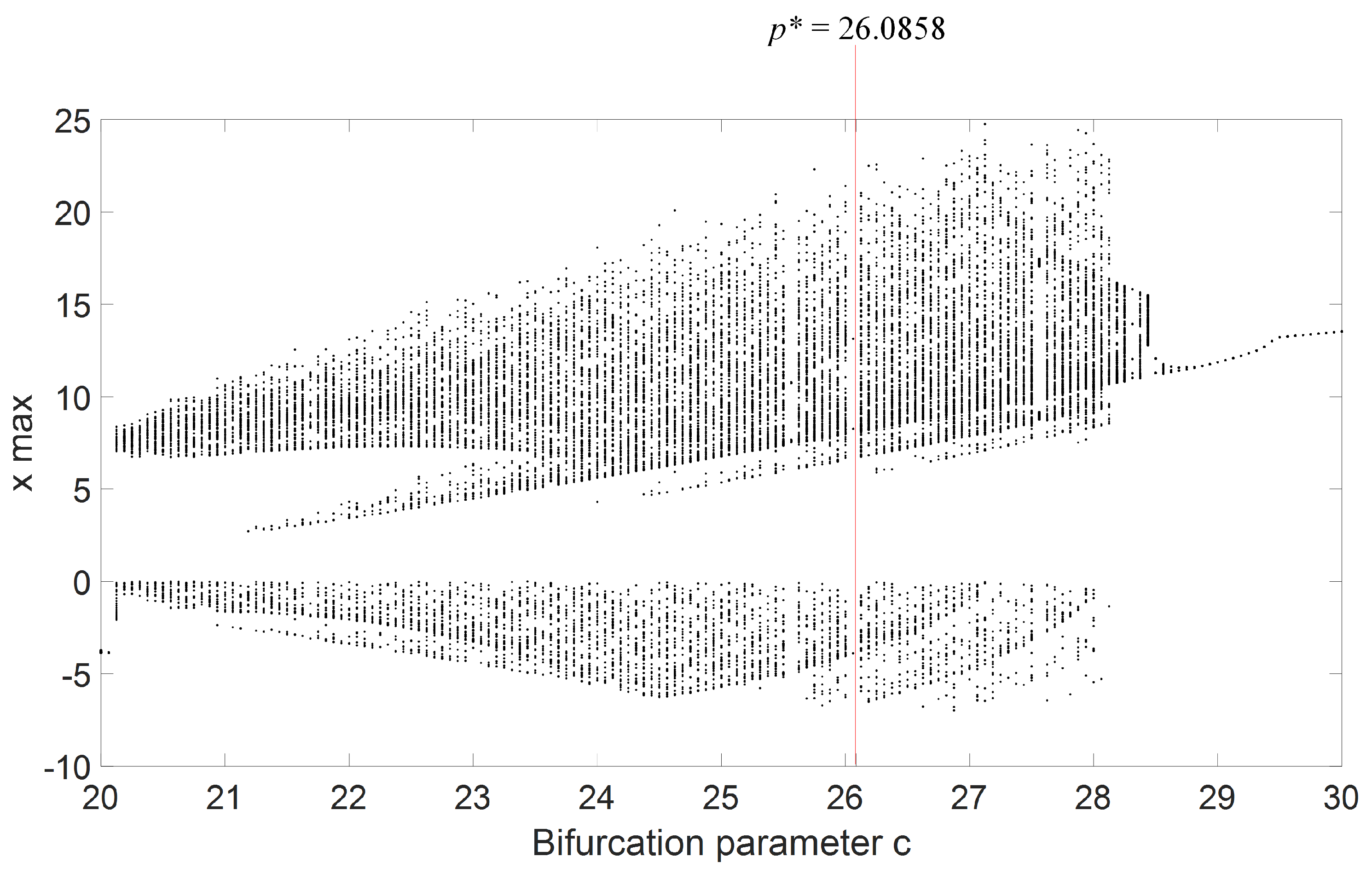
To numerically implement the parameter-switching scheme, it was required to choose a numerical technique with a fixed step-value h to integrate the underlying initial value problem. The applied numerical method was the Runge–Kutta method (fourth order) where h = 0.001 . To approximate with the PS scheme the solution corresponding to p*, it was therefore important to find a set P and the corresponding set M , such that Equation (6) gives the searched value p*. For this work, N = 6; hence, P N = { p 1 , p 2 , p 3 , p 4 , p 5 , p 6 } , M N = { m 1 , m 2 , m 3 , m 4 , m 5 , m 6 } , and A N = { A p 1 , A p 2 , A p 3 , A p 4 , A p 5 , A p 6 } . Our P N = {24.75, 25.80, 27.08, 27.38, 26.38, 25.10}, selected from the chaotic window in the bifurcation diagram in Figure 2, as parameter c was varied. M N = {3, 2, 4, 1, 1, 1} was chosen such that Equation (6) was verified, obtaining the “averaged” parameter p* = 26.0858, which corresponds to the stable window at c = p* = 26.0858 in Figure 2.
The corresponding PS scheme is thus:
[ m 1 p 1 , m 2 p 2 , m 3 p 3 , m 4 p 4 , m 5 p 5 , m 6 p 6 ] = [ 3 p 1 , 2 p 2 , 4 p 3 , 1 p 4 , 1 p 5 , 1 p 6 ]
Several tools can be employed to numerically verify the approximation of the “averaged” attractor A* by the synthesized attractor A S . In this investigation, three-dimensional phase plots (after neglecting enough transient period) and time series were used.
For example, to obtain the stable cycle corresponding to the “averaged” parameter p* with our P N and M N and using the PS scheme in (14), Equation (6) was evaluated to obtain p* = 26.0858. The PS scheme in (14) was applied to the IVP in (2) to obtain a synthesized attractor A S , which is the numerical approximation of the “averaged” attractor A* from p*.
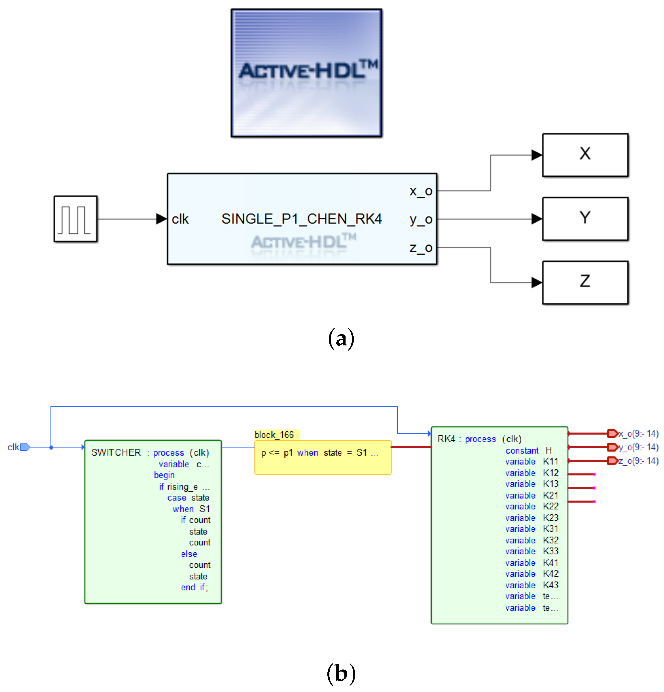
Figure 3a shows the co-simulation diagram of the implementation of the Chen model in Active-HDL with MATLAB/Simulink. Embedded in the S I N G L E _ P 1 _ C H E N _ R K 4 block is the numerical solution of the Chen model by fourth-order Runge–Kutta method, while X, Y, and Z are the outputs from the state variables. Figure 3b is the block diagram of the VHDL implementation of the PS scheme in Active-HDL. Processes SWITCHER and RK4 implemented the PS scheme with the fourth-order Runge–Kutta method, while x _ 0 , y _ 0 , and z _ 0 are the outputs.
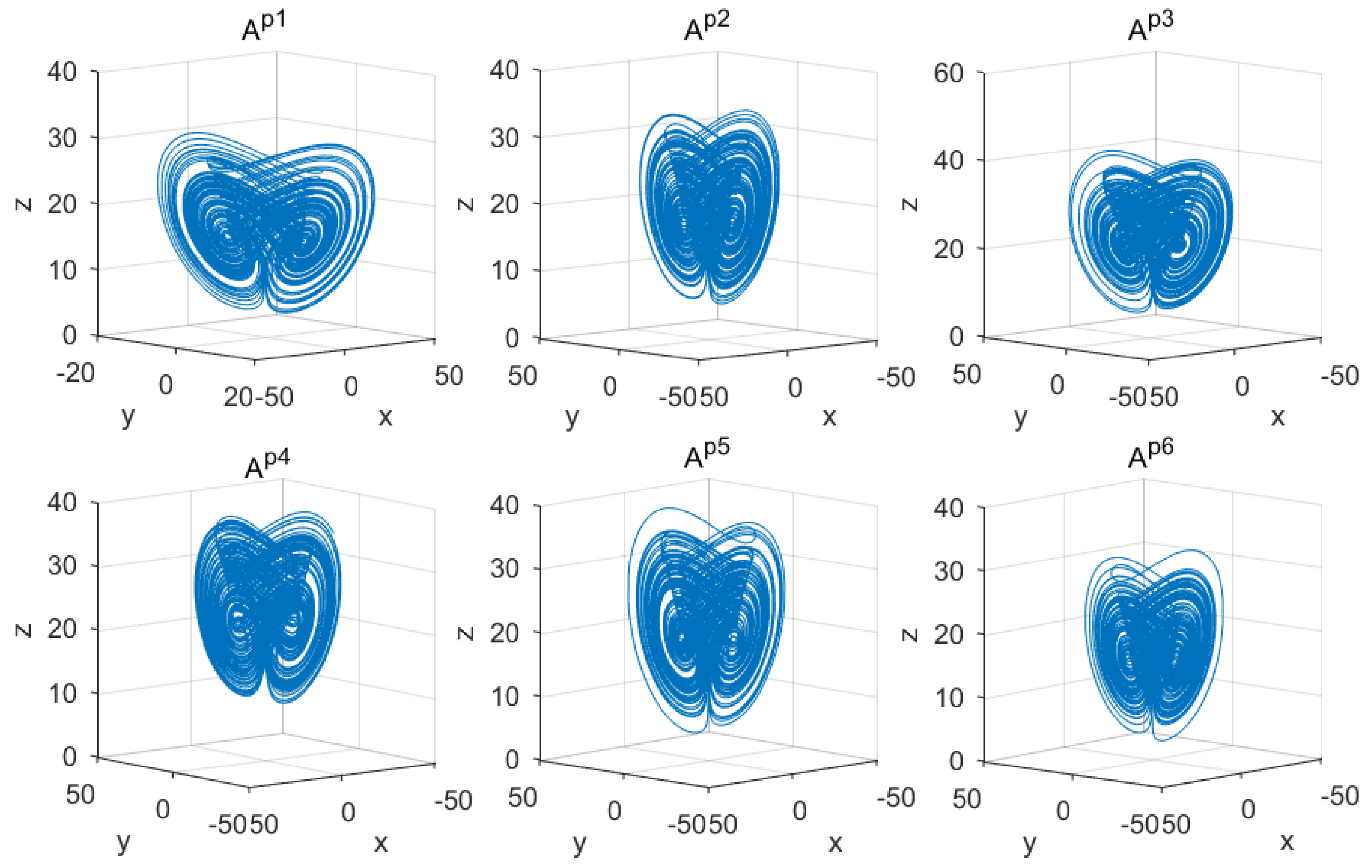
In Figure 4 are the underlying chaotic attractors A p 1 , A p 2 , A p 3 , A p 4 , A p 5 , and A p 6 in 3D corresponding to parameters p 1 = 24.75, p 2 = 25.80, p 3 = 27.08, p 4 = 27.38, p 5 = 26.38, and p 6 = 25.10, respectively, obtained from MATLAB and Active-HDL co-simulation of the Chen model using the same parameters and initial condition.
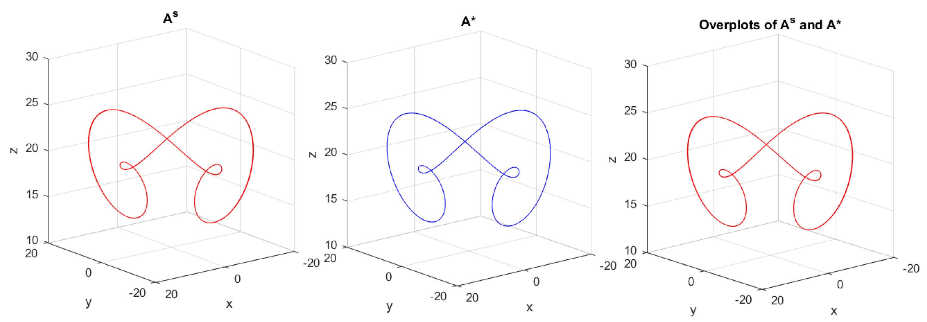
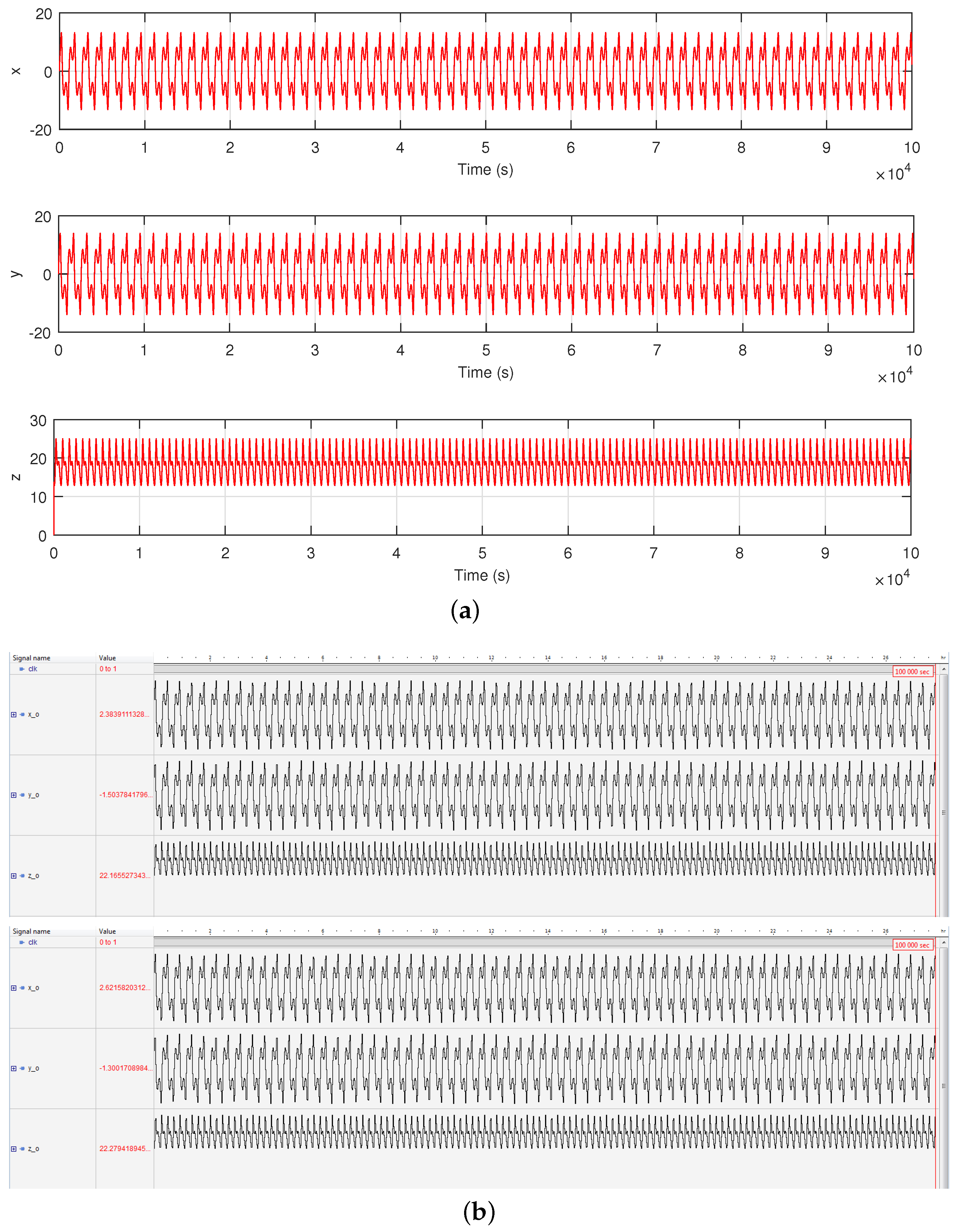
Furthermore, Figure 5 and Figure 6 present the results of the approximation of stable cycles of the Chen oscillator by the parameter-switching algorithm. In Figure 5 are the phase portraits in 3D, showing the “switched” solution A S (red), “averaged” solution A* (blue), and overplots of A S and A*, at p = p* = 26.0858 by the parameter-switching scheme [ m 1 p 1 , m 2 p 2 , m 3 p 3 , m 4 p 4 , m 5 p 5 , m 6 p 6 ] , where m 1 = 3, m 2 = 2, m 3 = 4, m 4 = 1, m 5 = 1, m 6 = 1 and p 1 = 24.75, p 2 = 25.80, p 3 = 27.08, p 4 = 27.38, p 5 = 26.38, p 6 = 25.10. Figure 6 is the system time series of the three states x, y, and z of the Chen system. The time series in MATLAB were plotted by superimposing the “switched” solution over the “averaged” solution to show the matching. The obtained attractors A S and A* were indeed stable cycles.
Looking closely at the considered PS scheme, it is noted that the stable attractors A S were synthesized from the combination of six underlying unstable attractors A p 1 , A p 2 , A p 3 , A p 4 , A p 5 , and A p 6 in Figure 4. This can be expressed in the form:
A p 1 C h a o s + A p 2 C h a o s + A p 3 C h a o s + A p 4 C h a o s + A p 5 C h a o s + A p 6 C h a o s = A S O r d e r
The expression in (15) is akin to the generalized Parrondo’s paradox [55,58,59]. In this situation, our PS scheme served as the chaos control mechanism in the Chen oscillator.

3.2. Master–Slave Synchronization

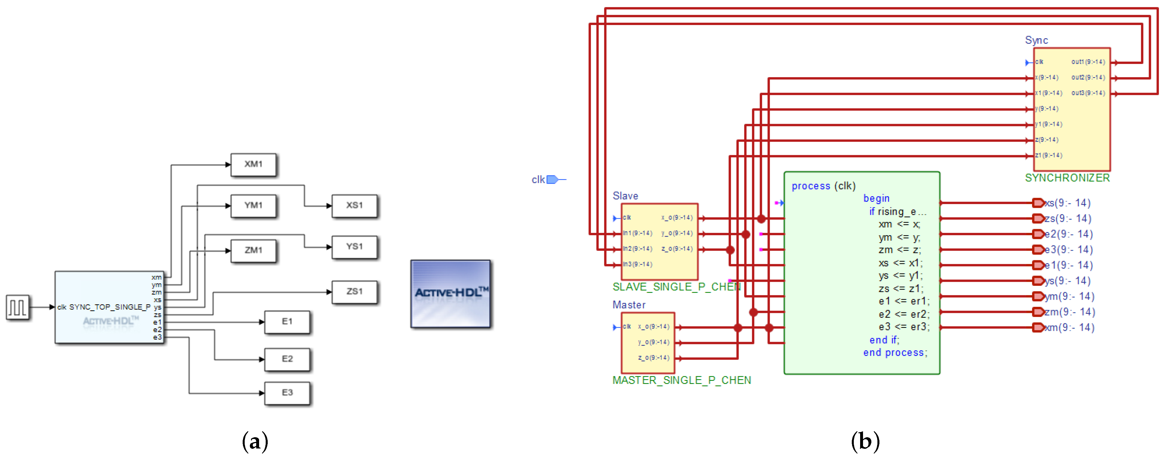
In this work, the system parameter values for the synchronization of the Chen oscillators were a = 35, b = 3. For parameter c, all six values in the set P N were separately used. The chosen gains of the observer were k 1 = 2, k 2 = 100, and k 3 = 0. The synchronization errors were computed and plotted as e 1 = x 1 ξ 1 , e 2 = x 2 ξ 2 , e 3 = x 3 ξ 3 , in which x i is the master system and ξ i is the slave system. The phase error between x i and ξ i is plotted as well. The total number of samples was 10 × 10 4 . Figure 7a shows the co-simulation diagram of the synchronization in MATLAB/Simulink, whereby X M 1 , Y M 1 , and Z M 1 are the outputs of the master system, X S 1 , Y S 1 , and Z S 1 are the outputs of the slave system, while E 1 , E 2 , and E 3 are the synchronization errors. The block S Y N C _ T O P _ S I N G L E _ P contains the function that performs the synchronization of the master and slave systems. Figure 7b represents the Active-HDL block diagram in the VHDL implementation. The entities Master and Slave represent the master and slave systems, respectively, while entity Sync handles the synchronization process. For the master system, the outputs are x m , y m , and z m ; for the slave system, the outputs are x s , y s , and z s ; while the synchronization errors are e 1 , e 2 , and e 3 .
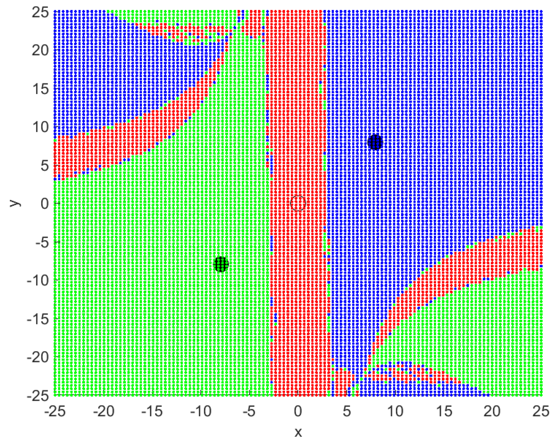
Two cases of synchronization, co-simulated in MATLAB and Active-HDL, are presented in this section. In the first case, the synchronization used different initial conditions as follows: x 0 = (4.075, 4.425, 13.73) for the master system and ξ 0 = (3, 3.5, 10.5) for the slave system. The second case used the same initial condition, x 0 = (4.075, 4.425, 13.73), for the master system, as well as the slave system. Initial conditions of the systems were randomly selected from the basins of attraction, out of the many possible values. The basins of attraction of the Chen system (1) can be visualized in Figure 8. It was computed using the Newton–Raphson method [60,61]. To plot the basins, the chosen upper and lower bounds within the state space were x = [ 25 , 25 ] , y = [ 25 , 25 ] , and z = [ 30 , 50 ] . The points in red color converge to the equilibrium point E P 0 represented by the black diamond shape, while those in green and blue converge to the equilibrium points E P 1 and E P 2 indicated by the two black circles, respectively. The eigenvalues at the three equilibria had at least one positive value, hence the possibility of strange attractors.
Both the master and slave chaotic oscillators were sensitive to the respective initial values. This was confirmed by computing the Lyapunov exponents, which for each initial condition had a positive value. In both cases, the master and slave phase diagrams, the phase errors, and the synchronization errors were analyzed. Perfect synchronization was achieved, considering the synchronization and phase error plots, for all the values of parameter c starting with c = p 1 , in which the error signals e 1 , e 2 and e 3 became zero (the same results were obtained for p 2 p 6 ). Therefore, suffice it to say that the ratio between the master state x i and slave state ξ i was one when the synchronization was achieved.

4. Application in Image Transmission

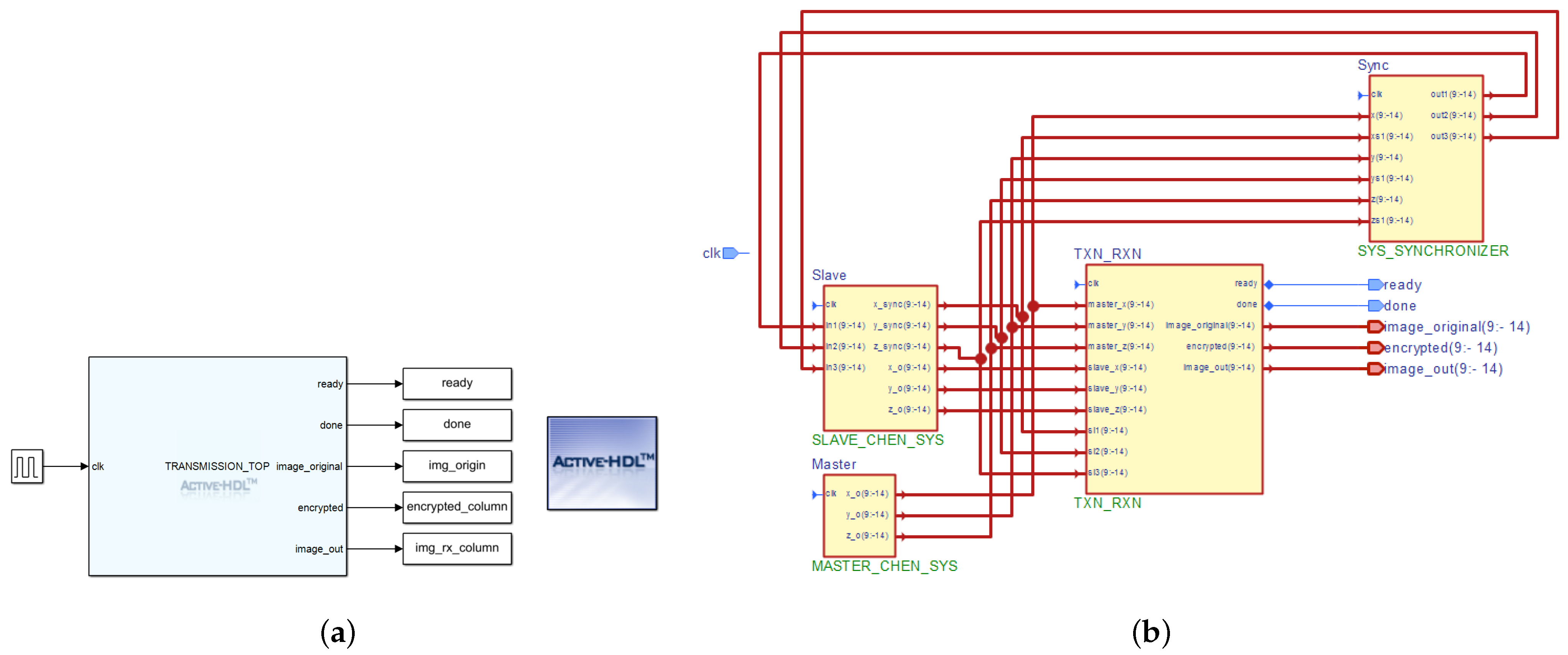
In this section, the synchronized Chen oscillators in the previous section are applied to develop a system for secure communication, to transmit grayscale and RGB images of size 640 × 480 pixels (307,200 words) and 320 × 240 pixels (230,400 words), respectively. Furthermore, the implementation of the image transmission system was co-simulated in both MATLAB/Simulink and Active-HDL. The main attraction here was the application of the parameter-switching technique to decrypt a transmitted (encrypted) image. In the communication concept, the master system is the transmitter subsystem, while the slave system is the receiver subsystem. The co-simulation diagram of the image transmission system in Simulink with Active-HDL and the Active-HDL block diagram are shown in Figure 9, respectively. In Figure 9a, img_origin, encrypted_column, and img_rx_column from the output ports generate the original image, the encrypted image, and the decrypted image signals, respectively, in MATLAB, and the function that coordinates the image transmission is embedded in the T R A N S M I S S I O N _ T O P block. On the other hand, Figure 9b contains four entities, namely Master, which is the master system, Slave, the slave system, Sync, the synchronization unit, and TXN_RXN, the unit that handles the actual image transmission. The original, encrypted, and decrypted image signals were received via image_original, encrypted, and image_out output ports.
The image transmission system is briefly described in the following three- step methodology:
Step 1: Creating the original RGB and grayscale image data in VHDL.
Step 2: Encrypting the original image with the chaotic state of the master system, e.g., master_x, in the TXN_RXN entity in Figure 8 (the master system is developed with any of the parameters in P N ).
Step 3: Recovering the image data, e.g., image_out, from the encrypted signal by removing chaos using the corresponding state of the slave system, e.g., slave_x.
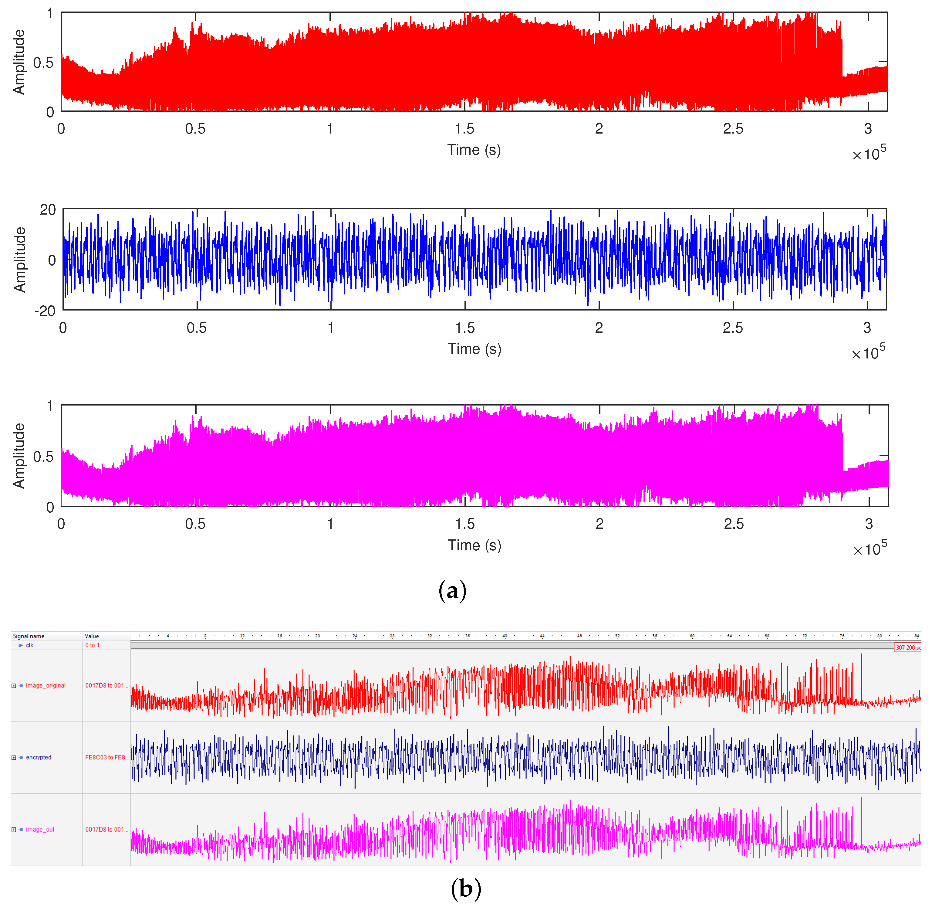
In this work, the three states x, y, and z were applied as transmission variables to encrypt and decrypt the images. The total simulation time for the RGB image transmission was 234,400 samples and 311,200 samples for grayscale image transmission. It is important to state that the initial conditions and the system parameters were private keys in the encryption and decryption, making the system a symmetric one. The co-simulation results from Active-HDL with Simulink, showing the original, encrypted, and received image data, are shown in Figure 10 for the grayscale image and Figure 11 for the RGB image. In both figures, the original images (in red color) are mixed with chaos to give the encrypted images (in blue color). Moreover, with respect to Figure 9, the original image signals were obtained from the img_origin and image_origin ports, encrypted image signals from the encrypted_column and encrypted ports, and the received image signals via the img_rx_column and image_out ports.
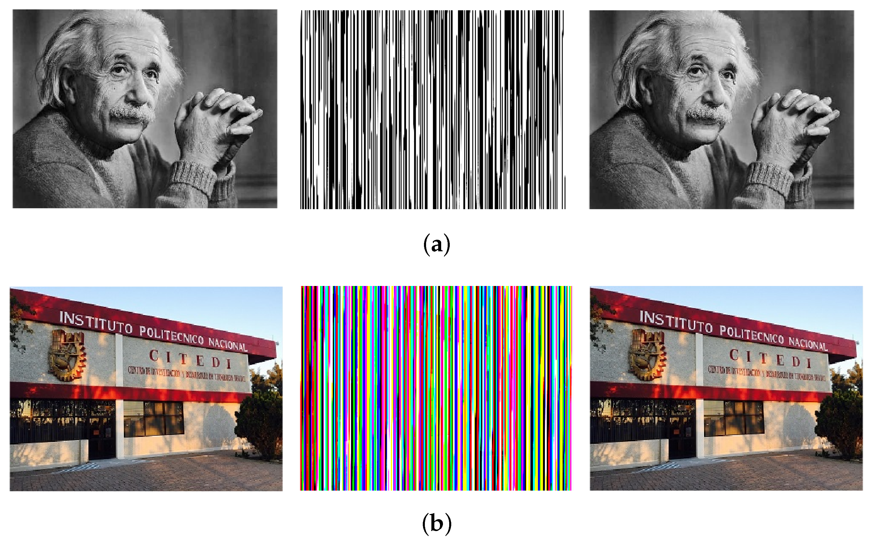
In Figure 12a,b are found the actual original, encrypted, and recovered grayscale and RGB images obtained from our best result, respectively. Statistical analyses were performed in MATLAB to find the correlation between the original and encrypted images, encrypted and received images, and original and received images. The results are presented in Table 1.

5. Discussion

The nonlinearities inherent in the Chen model (1) help give rise to the chaotic attractors in Figure 4. Upon the application of the parameter-switching scheme to evaluate the Chen model, effectively evaluating six different Chen chaotic systems in turn in the process, a stable Chen system was obtained. Suffice it to say that chaos in the underlying six chaotic attractors was controlled to give rise to a stable cycle (see the “switched” solution A S in Figure 5).
The backbone of the image transmission system in Figure 9 was the synchronized master and slave Chen systems. The slave unit Slave had embedded in it a parameter switching unit, which used the scheme in (14) to stabilize chaos in the master system to recover the encrypted image data. In the results presented in Figure 10, Figure 11 and Figure 12, each pixel of the original grayscale and RGB image data was blended with the chaotic state of the master unit to create the encrypted image data. Specifically, in Figure 10 and Figure 11, it is observed that the encrypted image data became random. The randomness in the encrypted images rendered them meaningless to potential hackers. After the images were reconstructed, the randomness was removed, and it can be seen that the recovered images were exactly the same as the original images. This result was significant because the recovery was achieved by applying the parameter-switching technique.
In the correlation results in Table 1, it is shown that with a correlation of one between the original and received images for both the RGB and grayscale images, the transmitted images were recovered fully without any loss of quality by applying the parameter-switching technique for the decryption. Considering the security of the encrypted images, given by the correlation between the original and encrypted images, our best result was obtained from variable y for the RGB images and x for the grayscale image. As a matter of fact, the correlations between the original and encrypted grayscale and RGB images, as well as between the encrypted and received grayscale and RGB images were the same, meaning that both the original and received images were the same. Moreover, the computed mean-squared error (MSE) was zero; hence, the peak-signal-to-noise ratio (PSNR) tended to infinity. This revelation was attributed to the fact that the chaos-based transmission system was resistant to noise and distortion [62].
All the work carried out in this investigation, namely the implementation of the Chen oscillator, the synthesis of attractors by the parameter-switching scheme, the synchronization of Chen oscillators, and image transmission, was realized on an FPGA device. As stated earlier, the HDL used was VHDL, and the size of the digital block was twenty-four bits: the integer segment used nine bits; the fraction occupied fourteen bits and one bit for the sign. The FPGA emulations were performed on the Xilinx Artix-7 AC701 board Device Number XC7A200TFBG676-2. The FPGA resources consumed by the activities listed above are presented in Table 2. As we can see, each of the activities required only less than one percent of the total registers on the FPGA board for the implementation. The same amount of FPGA resources was utilized to implement the Chen chaotic oscillator and the parameter-switching scheme to approximate stable cycles of the Chen oscillator.
Table 3 exhibits the utilization of FPGA resources for the image transmission,: the grayscale consumed more resources than the RGB, in particular with the amount of utilized slice LUTs. The difference in the slice LUTs utilization was attributed to the size of the images, which were 307,200 words for the grayscale and 230,400 words for the RGB image.
The secure communication system realized on the Intel’s Artix-7 AC701 board in this investigation was compared with some other implementations [38,63,64,65], using some of the FPGA resources and other parameters such as the type of board, the numerical method applied, the language of implementation, and the format of the fixed-point number. This is presented in Table 4. The FPGA resource consumption on Artix-7 AC701 performed favorably against the compared works.
At this juncture, it is important to state that, compared to other systems of communication, like the spread spectrum [66,67], the chaos-based image transmission system implemented in this investigation had the advantage of simplicity. The major subsystems were the master (transmitter) and the slave (receiver), unlike the traditional methods, which have many subsystems. Another merit is that the implemented system employed the chaotic states for both synchronization and encryption, unlike the other communication methods, which use a tool for synchronization and another for encryption. Furthermore, in terms of the number of rounds needed for encryption and decryption, our method used just a single round for each operation, as against several rounds in methods such as the Advanced Encryption Standard (AES) and the Data Encryption Standard (DES) [68,69]. Moreover, the chaos-based transmission system was resistant to noise and distortion. Lastly, our encryption system was less susceptible to security attacks because of the very large key space provided by the parameters and the initial condition.

6. Conclusions

The digital implementation of the parameter-switching scheme as the chaos control mechanism was highlighted in this paper. In another situation, parameter switching can function as the chaos anti-control mechanism, whereby two or more underlying stable attractors are combined to synthesize a chaotic attractor. The first major contribution of this work was the FPGA realization of the parameter-switching scheme to approximate stable cycles of the Chen oscillator. The second major contribution was the FPGA realization of a secure communication system whereby the parameter-switching scheme was applied as a decryption mechanism to recover chaos-encrypted RGB and grayscale images. In addition, the Chen chaotic model and master–slave synchronization by Hamiltonians and the observer-based approach were also realized on an FPGA device. In each activity, co-simulation results in MATLAB/Simulink and Active-HDL were presented to verify the FPGA realizations. In the case of the image transmission, the results of our experiment confirmed that the method implemented in this work was beneficial to secure communication systems. The bit depth of the grayscale image was eight bits, while the RGB was twenty-four bits, but our method is applicable to images of any bit depth.

Author Contributions

Conceptualization, J.-C.N.-P., V.-A.A., F.-J.P.-P., and E.T.-C.; methodology, J.-C.N.-P., V.-A.A., and E.T.-C.; software, V.-A.A. and Y.S.I.; validation, J.-C.N.-P., Y.S.I., F.-J.P.-P., and E.T.-C.; formal analysis, J.-C.N.-P., V.-A.A., Y.S.I., and E.T.-C.; investigation, J.-C.N.-P., V.-A.A., and F.-J.P.-P.; resources, J.-C.N.-P. and E.T.-C.; writing—original draft preparation, J.-C.N.-P., V.-A.A., and E.T.-C.; writing—review and editing, J.-C.N.-P., V.-A.A., Y.S.I., F.-J.P.-P., and E.T.-C.; visualization, V.-A.A., F.-J.P.-P., and Y.S.I.; supervision, J.-C.N.-P. and E.T.-C.; project administration, J.-C.N.-P.; funding acquisition, J.-C.N.-P. All authors read and agreed to the published version of the manuscript.

Funding

The authors wish to thank the Instituto Politecnico Nacional for its support provided through the project SIP-20210345. In addition, the authors would like to express their gratitude to the COFAA-IPN for its financial support.

Institutional Review Board Statement

Not applicable.

Informed Consent Statement

Not applicable.

Data Availability Statement

Not applicable.

Conflicts of Interest

The authors declare no conflict of interest.

Abbreviations

The following abbreviations are used in this manuscript:
DSPDigital signal processor
FPGAField programmable gate Array
HDLHardware design language
I/OInput/output
IVPInitial value problem
LUTLookup table
OGYOtt, Grebogi, and Yorke
PSParameter switching
RAMRandom access memory
RGBRed, green and blue
TRNGTrue random number generator
UPOUnstable periodic orbit
VHDLVery high-speed integrated circuit Hardware Design Language

References

  1. Nicolis, G. Chapter 1—The many facets of complexity. In Complexity Science: An Introduction; Peletier, M.A., van Santen, R.A., Steur, E., Eds.; World Scientific Publishing Co.: Singapore, 2019; pp. 3–30. ISBN 978-981323960-9. [Google Scholar]
  2. Hu, M.; Li, F. A new method to solve numeric solution of nonlinear dynamic system. Math. Probl. Eng. 2016, 2016, 1485759. [Google Scholar] [CrossRef] [Green Version]
  3. Li, X.; Liao, S. Clean numerical simulation: A new strategy to obtain reliable solutions of chaotic dynamics. Appl. Math. Mech. Engl. Ed. 2018, 39, 1529–1546. [Google Scholar] [CrossRef] [Green Version]
  4. Lozi, R.; Pchelinstev, A.N. A new reliable numerical method for computing chaotic solutions of dynamical systems: The Chen attractor case. Int. J. Bifurc. Chaos 2015, 25, 1550187. [Google Scholar] [CrossRef] [Green Version]
  5. Haq, B.U.; Naeem, I. First integrals and analytical solutions of some dynamical systems. Nonlinear Dyn. 2019, 95, 1747–1765. [Google Scholar] [CrossRef]
  6. Mellodge, P. Chapter 4—Characteristics of Nonlinear Systems. In A Practical Approach to Dynamical Systems for Engineers; Mellodge, P., Ed.; Woodhead Publishing: Cambridge, UK, 2016; pp. 215–250. ISBN 9780081002025. [Google Scholar]
  7. Ling, W.K. Nonlinear Digital Filters: Analysis and Applications; Academic Press: New York, NY, USA, 2010; ISBN 9780080550015. [Google Scholar]
  8. Puy, A.; Daza, A.; Wagemakers, A.; Sanjuán, M.A.F. A test for fractal boundaries based on the basin entropy. Commun. Nonlinear Sci. Numer. Simul. 2021, 95, 105588. [Google Scholar] [CrossRef]
  9. Goufo, E.F.D.; Khan, Y. A new auto-replication in systems of attractors with two and three merged basins of attraction via control. Commun. Nonlinear Sci. Numer. Simul. 2021, 96, 105709. [Google Scholar] [CrossRef]
  10. Yan, Y.; Xu, J.; Wiercigroch, M.; Guo, Q. Statistical basin of attraction in time-delayed cutting dynamics: Modelling and computation. Phys. D Nonlinear Phenom. 2021, 416, 132779. [Google Scholar] [CrossRef]
  11. Lee, M.Y.; Kim, Y.I. Development of a Family of Jarratt-Like Sixth-Order Iterative Methods for Solving Nonlinear Systems with their basins of attraction. Algorithms 2020, 13, 303. [Google Scholar] [CrossRef]
  12. Rabenimananaa, T.; Walter, V.; Kacem, N.; Le Moal, P.; Bourbon, G.; Lardiès, J. Functionalization of electrostatic nonlinearities to overcome mode aliasing limitations in the sensitivity of mass microsensors based on energy localization editors-pick. Appl. Phys. Lett. 2020, 117, 033502. [Google Scholar] [CrossRef]
  13. Ngo, G.Q.; George, A.; Schock, R.T.K.; Tuniz, A.; Najafidehaghani, E.; Gan, Z.; Geib, N.C.; Bucher, T.; Knopf, H.; Saravi, S.; et al. Scalable functionalization of optical fibers using atomically thin semiconductors. Adv. Mater. 2020, 32, e2003826. [Google Scholar] [CrossRef]
  14. Rajagopal, K.; Akgul, A.; Jafari, S.; Karthikeyan, A.; Cavusoglu, U.; Kacar, S. An exponential jerk system, its fractional-order form with dynamical analysis and engineering application. Soft Comput. 2020, 24, 7469–7479. [Google Scholar] [CrossRef]
  15. Quan, G.Z.; Ma, Y.Y.; Zhang, Y.Q.; Zhang, P.; Wang, W.Y. Separation of dynamic recrystallization parameter domains from a chaotic system for Ti–6Al–4V alloy and its application in parameter loading path design. Mater. Sci. Eng. A 2020, 772, 138745. [Google Scholar] [CrossRef]
  16. Changaival, B.; Rosalie, M.; Danoy, G.; Lavangnananda, K.; Bouvry, P. Chaotic Traversal (CHAT): Very Large Graphs Traversal Using Chaotic Dynamics. Int. J. Bifurc. Chaos 2017, 27, 1750215. [Google Scholar] [CrossRef] [Green Version]
  17. Li, C.T.; Lee, C.C.; Weng, C.Y.; Chen, S.J. A Secure Dynamic Identity and Chaotic Maps Based User Authentication and Key Agreement Scheme for e-Healthcare Systems. J. Med. Syst. 2016, 40, 233. [Google Scholar] [CrossRef]
  18. Zang, X.; Iqbal, S.; Zhu, Y.; Liu, X.; Zhao, J. Applications of Chaotic Dynamics in Robotics. Int. J. Adv. Robot. Syst. 2016, 13. [Google Scholar] [CrossRef] [Green Version]
  19. Akgul, A.; Moroz, I.; Pehlivan, I.; Vaidyanathan, S. A new four-scroll chaotic attractor and its engineering applications. Optik 2016, 127, 5491–5499. [Google Scholar] [CrossRef]
  20. Ott, E. Chaos in Dynamical Systems; Cambridge University Press: Cambridge, UK, 1993. [Google Scholar]
  21. Din, Q. Qualitative analysis and chaos control in a density-dependent host-parasitoid system. Int. J. Dyn. Control 2018, 6, 778–798. [Google Scholar] [CrossRef]
  22. Nobakhti, E.; Khaki-Sedigh, A.; Vasegh, N. Control of multichaotic systems using the extended OGY method. Int. J. Bifurc. Chaos 2015, 25, 1550096. [Google Scholar] [CrossRef]
  23. Din, Q.; Elsadany, A.A.; Ibrahim, S. Bifurcation analysis and chaos control in a second order rational difference equation. Int. J. Nonlinear Sci. Numer. Simul. 2018, 19, 53–68. [Google Scholar] [CrossRef]
  24. Leonov, G.A. Pyragas stabilizability via delayed feedback with periodic control gain. Syst. Control Lett. 2014, 69, 34–37. [Google Scholar] [CrossRef]
  25. Xu, C.; Zhang, Q. On the chaos control of the Qi system. J. Eng. Math. 2015, 90, 67–81. [Google Scholar] [CrossRef]
  26. Amster, P.; Alliera, C. Control of Pyragas applied to a coupled system with unstable periodic orbits. Bull. Math. Biol. 2018, 80, 2897–2916. [Google Scholar] [CrossRef] [PubMed]
  27. Schwartz, I.B.; Triandaf, I.; Meucci, R.; Carr, T.W. Open-loop sustained chaos and control: A manifold approach. Phys. Rev. E 2002, 66, 026213. [Google Scholar] [CrossRef] [PubMed]
  28. Li, Y.N.; Yang, Y.T.; Zhu, Z.M.; Zhang, C.L. Feed-forward slope compensated PFC for chaos control. J. Circuits Syst. Comput. 2015, 25, 1550065. [Google Scholar] [CrossRef]
  29. Danca, M.-F.; Chattopadhyay, J. Chaos control of Hastings-Powell model by combining chaotic motions. Chaos 2016, 26, 043106. [Google Scholar] [CrossRef] [PubMed] [Green Version]
  30. Danca, M.-F.; Garrappa, R.; Tang, W.K.S.; Chen, G. Sustaining stable dynamics of a fractional-order chaotic financial system by parameter switching. Comput. Math. Appl. 2013, 66, 702–716. [Google Scholar] [CrossRef]
  31. Danca, M.-F.; Lung, N. Parameter switching in a generalized Duffing system: Finding the stable attractors. Appl. Math. Comput. 2013, 223, 101–114. [Google Scholar] [CrossRef] [Green Version]
  32. Núñez-Pérez, J.C.; Adeyemi, V.A.; Sandoval-Ibarra, Y.; Pérez-Pinal, F.J.; Tlelo-Cuautle, E. FPGA Realization of Spherical Chaotic System with Application in Image Transmission. Math. Probl. Eng. 2021, 2021, 5532106. [Google Scholar] [CrossRef]
  33. Tuna, M.; Alçın, M.; Koyuncu, I.; Fidan, C.B.; Pehlivan, I. High speed FPGA-based chaotic oscillator design. Microprocess. Microsystem. 2019, 66, 72–80. [Google Scholar] [CrossRef]
  34. Yang, C.H.; Huang, S.J. Secure color image encryption algorithm based on chaotic signals and its FPGA realization. Int. J. Circuit Theory Appl. 2018, 46, 2444–2461. [Google Scholar] [CrossRef]
  35. Alçin, M.; Koyuncu, I.; Tuna, M.; Varan, M.; Pehlivan, I. A novel high speed artifical neural network-based chaotic true random number generator on field programmable gate array. Int. J. Circuit Theory Appl. 2018, 47, 365–378. [Google Scholar] [CrossRef]
  36. Li, P.; Zhang, W.; Li, Z.; Liu, W.; Halang, W.A. FPGA implementation of a coupled-map-lattice-based cryptosystem. Int. J. Circuit Theory Appl. 2010, 38, 85–98. [Google Scholar] [CrossRef]
  37. Tlelo-Cuautle, E.; de la Fraga, L.G.; Viet-Thanh, P.; Volos, C.; Jafari, S. Quintas-Valles, A.J. Dynamics, FPGA realization and application of a chaotic system with an infinite number of equilibrium points. Nonlinear Dyn. 2017, 89, 1129–1139. [Google Scholar] [CrossRef]
  38. Yu, F.; Liu, L.; He, B.; Huang, Y.; Shi, C.; Cai, S.; Song, Y.; Du, S.; Wan, Q. Analysis and FPGA realization of a novel 5D hyperchaotic four-wing memristive system, active control synchronization, and secure communication application. Complexity 2019, 2019, 4047957. [Google Scholar] [CrossRef] [Green Version]
  39. Azzaz, M.S.; Tanougast, C.; Maali, A.; Benssalah, M. An efficient and lightweight multi-scroll chaos-based hardware solution for protecting fingerprint biometric templates. Int. J. Commun. Syst. 2019, 33, e4211. [Google Scholar] [CrossRef]
  40. Hagras, E.A.A.; Saber, M. Low power and high-speed FPGA implementation for 4D memristor chaotic system for image encryption. Multimed. Tools Appl. 2020, 79, 23203–23222. [Google Scholar] [CrossRef]
  41. Guillén-Fernández, O.; Meléndez-Cano, A.; Tlelo-Cuautle, E.; Núñez-Pérez, J.C.; Rangel-Magdaleno, J.J. On the synchronization techniques of chaotic oscillators and their FPGA-based implementation for secure image transmission. PLoS ONE 2019, 14, e0209618. [Google Scholar] [CrossRef]
  42. Tlelo-Cuautle, E.; Díaz-Muñoz, J.D.; González-Zapata, A.M.; Li, R.; León-Salas, W.D.; Fernández, F.V.; Guillén-Fernández, O.; Cruz-Vega, I. Chaotic Image Encryption Using Hopfield and Hindmarsh–Rose Neurons Implemented on FPGA. Sensors 2020, 20, 1326. [Google Scholar] [CrossRef] [PubMed] [Green Version]
  43. Tlelo-Cuautle, E.; Pano-Azucena, A.D.; Guillén-Fernández, O.; Silva-Juárez, A. Synchronization and Applications of Fractional-Order Chaotic Systems. In Analog/Digital Implementation of Fractional Order Chaotic Circuits and Applications; Springer: Cham, Switzerland, 2019. [Google Scholar]
  44. Sivaraman, R.; Rajagopalan, S.; Amirtharajan, R. FPGA based generic RO TRNG architecture for image confusion. Multimed. Tools Appl. 2020, 79, 13841–13868. [Google Scholar] [CrossRef]
  45. Zeng, J.; Wang, C. A Novel Hyperchaotic Image Encryption System Based on Particle Swarm Optimization Algorithm and Cellular Automata. Secur. Commun. Netw. 2021, 2021, 6675565. [Google Scholar] [CrossRef]
  46. Wang, X.; Li, Y.; Jin, J. A new one-dimensional chaotic system with applications in image encryption. Chaos Solitons Fractals 2020, 139, 110102. [Google Scholar] [CrossRef]
  47. Li, Z.; Peng, C.; Tan, W.; Li, L. An Efficient Plaintext-Related Chaotic Image Encryption Scheme Based on Compressive Sensing. Sensors 2021, 21, 758. [Google Scholar] [CrossRef] [PubMed]
  48. Mohamed, A.G.; Korany, N.O.; El-Khamy, S.E. New DNA Coded Fuzzy Based (DNAFZ) S-Boxes: Application to Robust Image Encryption Using Hyper Chaotic Maps. IEEE Access 2021, 9, 14284–14305. [Google Scholar] [CrossRef]
  49. Núñez Pérez, J.C.; Adeyemi, V.A.; Sandoval-Ibarra, Y.; Serrato-Andrade, R.Y.; Cárdenas, J.R.; Tlelo-Cuautle, E. Mathematical and numerical analysis of the dynamical behavior of Chen oscillator. Int. J. Dyn. Control 2020, 8, 386–395. [Google Scholar] [CrossRef]
  50. Barboza, R. On the Lorenz and Chen Systems. Int. J. Bifurc. Chaos 2018, 28, 1850018. [Google Scholar] [CrossRef]
  51. Chen, G.; Ueta, T. Yet another chaotic attractor. Int. J. Bifurc. Chaos 1999, 9, 1465–1466. [Google Scholar] [CrossRef]
  52. Wang, X.; Chen, G. Generating Lorenz-like and Chen-like attractors from a simple algebraic structure. Sci. China Inf. Sci. 2014, 57, 1–7. [Google Scholar] [CrossRef] [Green Version]
  53. Danca, M.-F.; Feckan, M. Note on a parameter-switching method for nonlinear ODEs. Math. Slovaca 2016, 66, 439–448. [Google Scholar] [CrossRef] [Green Version]
  54. Tang, W.K.S.; Danca, M.-F. Emulating “Chaos + Chaos = Order” in Chen’s circuit of fractional order by parameter switching. Int. J. Bifurc. Chaos 2016, 26, 1650096. [Google Scholar] [CrossRef]
  55. Danca, M.-F. Convergence of a parameter switching algorithm for a class of nonlinear continuous systems and a generalization of Parrondo’s paradox. Commun. Nonlinear Sci. Numer. Simul. 2013, 18, 500–510. [Google Scholar] [CrossRef]
  56. Sira-Ramirez, H.; Cruz-Hernandez, C. Synchronization of chaotic systems: A generalized Hamiltonian systems approach. Int. J. Bifurc. Chaos 2001, 11, 1381–1395. [Google Scholar] [CrossRef]
  57. Pei, L.J.; Liu, S.H. Application of generalized Hamiltonian systems to chaotic synchronization. Nonlinear Dyn. Syst. Theory 2009, 9, 415–432. [Google Scholar]
  58. Danca, M.-F.; Tang, W.K.S. Parrondo’s paradox for chaos control and anticontrol of fractional-order systems. Chin. Phys. B 2016, 25, 010505. [Google Scholar] [CrossRef]
  59. Harmer, G.P.; Abbott, D. A review of Parrondo’s paradox. Fluct. Noise Lett. 2002, 2, R71–R107. [Google Scholar] [CrossRef] [Green Version]
  60. Kumar, V.; Aggarwal, R.; Sharma, P.; Kaur, B. Fractal basins of attraction in a binary quasar model. New Astron. 2021, 84, 101543. [Google Scholar] [CrossRef]
  61. Saeed, T.; Chen, W.; Zotos, E.E. Convergence properties of equilibria in the restricted three-body problem with prolate primaries. Astron. Nachrichten 2020, 341, 887–898. [Google Scholar] [CrossRef]
  62. Koppu, S.; Viswanatham, V.M. A fast enhanced secure image chaotic cryptosystem based on hybrid chaotic magic transform. Model. Simul. Eng. 2017, 2017, 7470204. [Google Scholar] [CrossRef] [Green Version]
  63. Chang, D.; Li, Z.; Wang, M.; Zeng, Y. A novel digital programmable multi-scroll chaotic system and its application in FPGA-based audio secure communication. AEU Int. J. Electron. Commun. 2018, 88, 20–29. [Google Scholar] [CrossRef]
  64. Tlelo-Cuautle, E.; Carbajal-Gomez, V.H.; Obeso-Rodelo, P.J.; Rangel-Magdaleno, J.J.; Núñez-Pérez, J.C. FPGA realization of a chaotic communication system applied to image processing. Nonlinear Dyn. 2015, 82, 1879–1892. [Google Scholar] [CrossRef]
  65. Sadoudi, S.; Tanougast, C.; Azzaz, M.S.; Dandache, A. Design and FPGA implementation of a wireless hyperchaotic communication system for secure real-time image transmission. EURASIP J. Image Video Process. 2013, 43. [Google Scholar] [CrossRef]
  66. Belo, D.; Carvalho, N.B. An OOK chirp spread spectrum backscatter communication system for wireless power transfer applications. IEEE Trans. Microw. Theory Tech. 2021, 69, 1838–1845. [Google Scholar] [CrossRef]
  67. Liu, M.; Han, Y.; Chen, Y.; Song, H.; Yang, Z.; Gong, F. Modulation parameter estimation of LFM interference for direct sequence spread spectrum communication system in Alpha-Stable noise. IEEE Syst. J. 2021, 15, 881–892. [Google Scholar] [CrossRef]
  68. Sheikhpour, S.; Mahani, A.; Bagheri, N. Reliable advanced encryption standard hardware implementation: 32-bit and 64-bit data-paths. Microprocess. Microsystem. 2021, 81, 103740. [Google Scholar] [CrossRef]
  69. Ikhwan, A.; Rafikha Aliana, A.R.; Ehkan, P.; Yacob, Y.; Syaifuddin, M. Data Security Implementation using Data Encryption Standard Method for Student Values at the Faculty of Medicine, University of North Sumatra. J. Phys. Conf. Ser. 2021, 1755, 012022. [Google Scholar] [CrossRef]
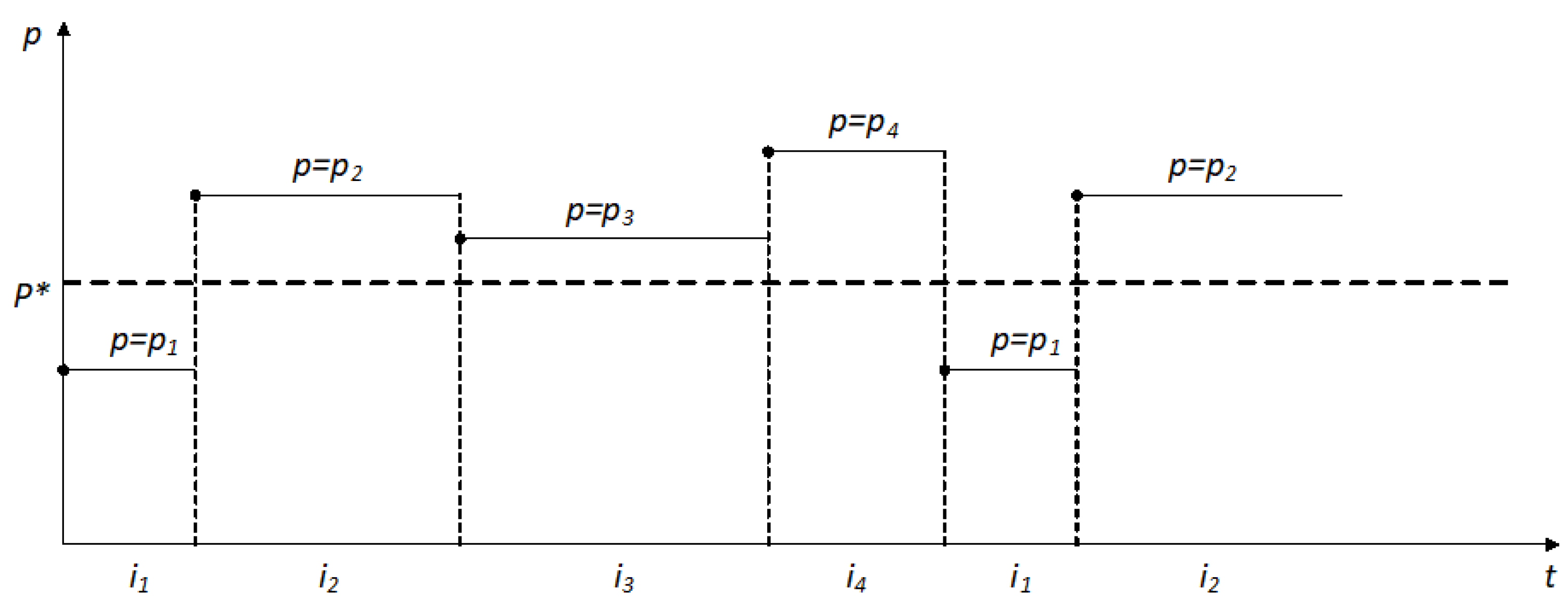
Figure 1. Parameter-switching scheme showing the switched parameters p k and their associated sub-interval i k times.
Symmetry 13 00923 g001
Figure 2. Bifurcation diagram of the Chen oscillator (1) showing the chaotic and stable regions as parameter c is varied. The “averaged” parameter p* = 26.0858 is selected from the stable window.
Symmetry 13 00923 g002
Figure 3. Chen oscillator and parameter-switching scheme using the 4th-order Runge–Kutta method. (a) Co-simulation in MATLAB/Simulink with Active-HDL. (b) Active-HDL block diagram of the VHDL implementation.
Symmetry 13 00923 g003
Figure 4. Chaotic phase portraits of the Chen system (1) for the set A N corresponding to P N .
Symmetry 13 00923 g004
Figure 5. Co-simulation results of the approximation of the Chen system’s stable cycle, illustrating the “switched” solution A S (red), “averaged” solution A* (blue), and overplots of A S and A*.
Symmetry 13 00923 g005
Figure 6. Time series of the three states x, y, and z. (a) MATLAB overplots: “switched” solution A S (red) and “averaged” solution A* (blue). (b) Active-HDL: “switched” solution A S (upper) and “averaged” solution A* (lower).
Symmetry 13 00923 g006
Figure 7. Hamiltonian synchronization of master and slave Chen systems. (a) Co-simulation in MATLAB/Simulink with Active-HDL. (b) Active-HDL block diagram of the VHDL implementation.
Symmetry 13 00923 g007
Figure 8. Basins of attraction of the Chen system (1) on x y plane at a = 35 , b = 3 , and c = 24.75 ; equilibrium point E P 0 has the red regions as its basin; equilibrium point E P 1 has green regions as its basin; while equilibrium point E P 2 has blue regions as its basin.
Symmetry 13 00923 g008
Figure 9. Image transmission system. (a) Co-simulation diagram in MATLAB/Simulink with Active-HDL. (b) Active-HDL block diagram.
Symmetry 13 00923 g009
Figure 10. Waveforms of the 640 × 480 grayscale image from transmission variable x, showing the original (red), encrypted (blue), and received (magenta) recovered by the parameter-switching technique. (a) Co-simulation diagram in MATLAB/Simulink with Active-HDL. (b) Active-HDL.
Symmetry 13 00923 g010
Figure 11. Waveforms of the 320 × 240 RGB image data from transmission variable y, showing the original (red), encrypted (blue), and received (magenta) recovered by the parameter-switching technique. (a) Co-simulation diagram in MATLAB/Simulink with Active-HDL. (b) Active-HDL.
Symmetry 13 00923 g011
Figure 12. Co-simulation image data, showing the original image (left), encrypted image (middle), and received image (right) recovered by the parameter-switching technique: (a) 640 × 480 grayscale image, transmitted via state variable x; (b) 320 × 240 RGB image, transmitted via state variable y.
Symmetry 13 00923 g012
Table 1. Correlation coefficients’ analysis of the original, encrypted, and received RGB and grayscale images, using the parameter-switching scheme for image decryption.
Transmission VariableCorrelationRGB ImageGrayscale Image
RedGreenBlue
xOriginal and Encrypted0.03420.05430.03150.0352
Encrypted and Received0.03420.05430.03150.0352
Original and Received1111
yOriginal and Encrypted0.03160.04980.02960.0362
Encrypted and Received0.03160.04980.02960.0362
Original and Received1111
zOriginal and Encrypted0.06490.07470.07110.0672
Encrypted and Received0.06490.07470.07110.0672
Original and Received1111
Table 2. Utilization of FPGA resources in the Xilinx Artix-7 AC701 board to implement the: (1) Chen chaotic oscillator, (2) parameter-switching scheme applied to approximate stable cycles of the Chen oscillator, and (3) the Hamiltonian form synchronization of Chen oscillators.
Chen OscillatorParameter SwitchingSynchronization
ResourcesAvailableUsedUtilization
(%)
UsedUtilization
(%)
UsedUtilization
(%)
Slice LUTs134,600561545472411,9359
Memory LUTs46,200000000
Registers269,200144<1179<1479<1
I/O pins4007318731814536
Block RAMs13,140,000000000
DSPs740446405649
Table 3. Utilization of FPGA resources in the Xilinx Artix-7 AC701 board to implement RGB and grayscale image transmissions by Chen oscillators using the parameter-switching scheme for decryption.
ResourcesAvailableRGB ImageGrayscale Image
UsedUtilization (%)UsedUtilization (%)
Slice LUTs134,60073,1575483,81062
Memory LUTs46,2000000
Registers269,200885<1948<1
I/O pins40075197519
Block RAMs13,140,0000000
DSPs7401041410414
Table 4. Comparing this work with other FPGA implementations of secure communication systems.
ParameterThis Work (RGB)This Work (Grayscale)Ref. [38]Ref. [63]Ref. [64]Ref. [65]
FPGAArtix-7Artix-7ZYNQCyclone IVStratix IVVirtex 5
Slice LUTs54%62%43%33%27%24%
Registers<1%<1%25%27%<1%5%
I/O pins19%19%24%N/A22%32%
Block RAMs0%0%N/A96%40%N/A
DSPs14%14%N/A24%7%62%
AlgorithmRK-4RK-4RK-4EulerEulerRK-4
LanguageVHDLVHDLVerilogVerilogVHDLVHDL
Number24 bit24 bit32 bit32 bit19 bit32 bit
Publisher’s Note: MDPI stays neutral with regard to jurisdictional claims in published maps and institutional affiliations.