Direct Power Compensation in AC Distribution Networks with SCES Systems via PI-PBC Approach

 ,
,  ,
,  ,
, 
Abstract
1. Introduction
2. Dynamical Modeling
3. Passivity-Based Control Design
3.1. Bilinear Representation
3.2. Lyapunov’s Requirements for Stability Analysis
3.3. PI-PBC Design
4. Control Structure and Physical Constraint
4.1. Control Law
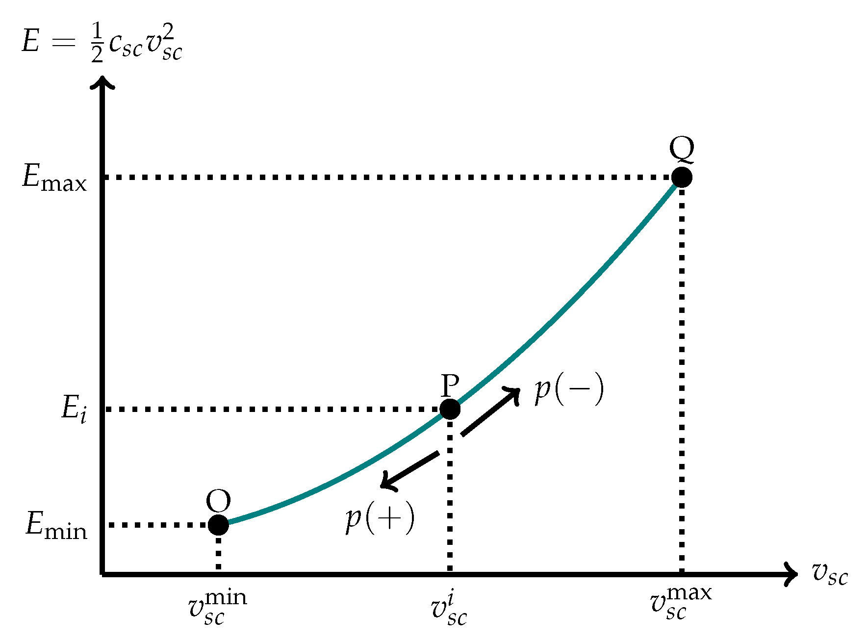
4.2. Physical Operative Constraint
5. Test System and Simulation Scenarios
5.1. The System Under Study
5.2. Simulation Scenarios
- Scenario 1 (S1): Check the proposed controller to manage the active and reactive power independently in the SCES system.
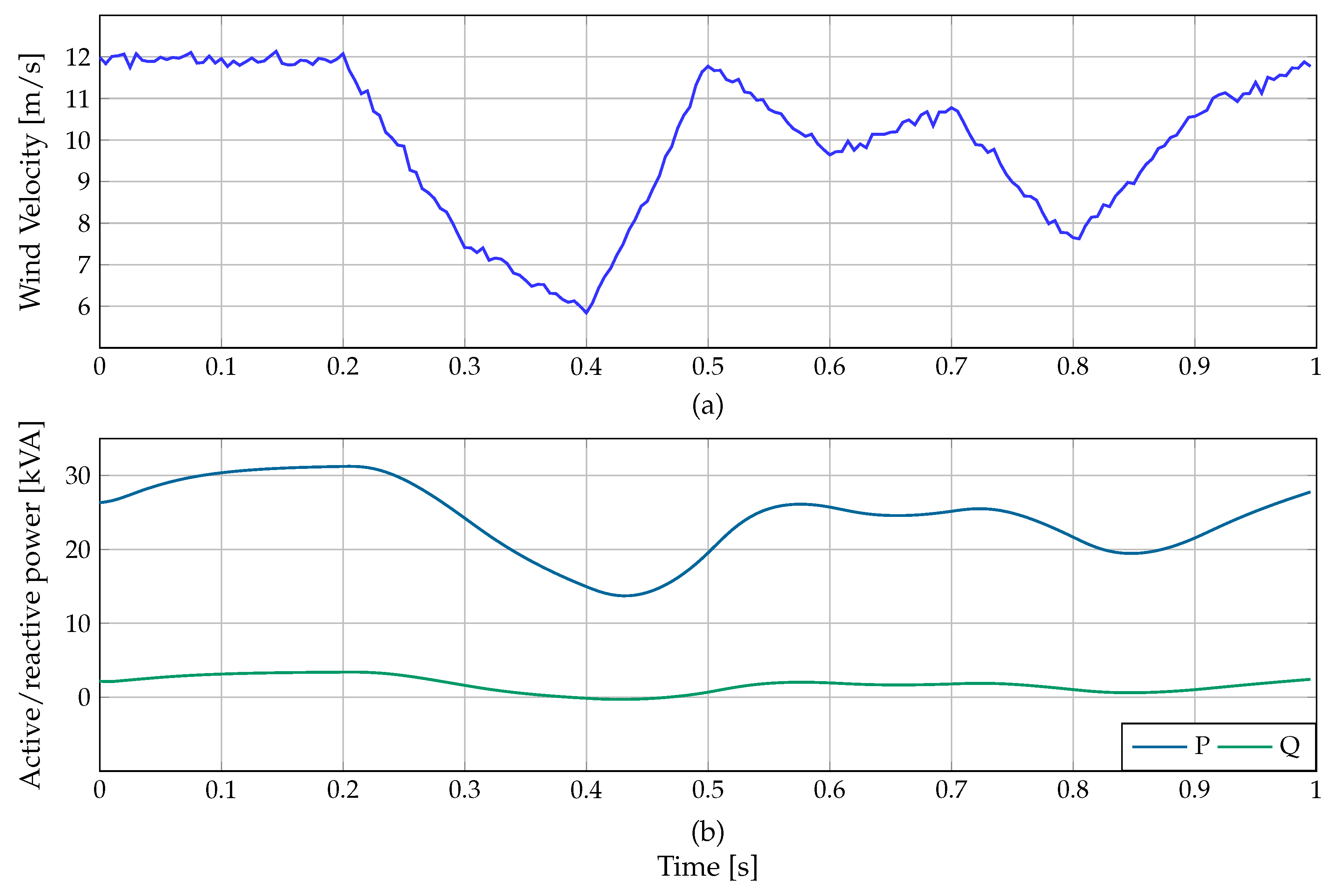
- Scenario 2 (S2): Evaluate the performance of the proposed controller applied to the SUCCESS system using the DPC model to relieve the oscillations of active and reactive power in the microgrid. This scenario employs a wind power generator located at bus 2, which provides active power and absorbs the reactive power shown in Figure 3. Additionally, the test system has two demands (see DL1 and DL2 loads in Figure 2), which draw active and reactive power, as depicted in Figure 4.
6. Results
6.1. Scenario 1
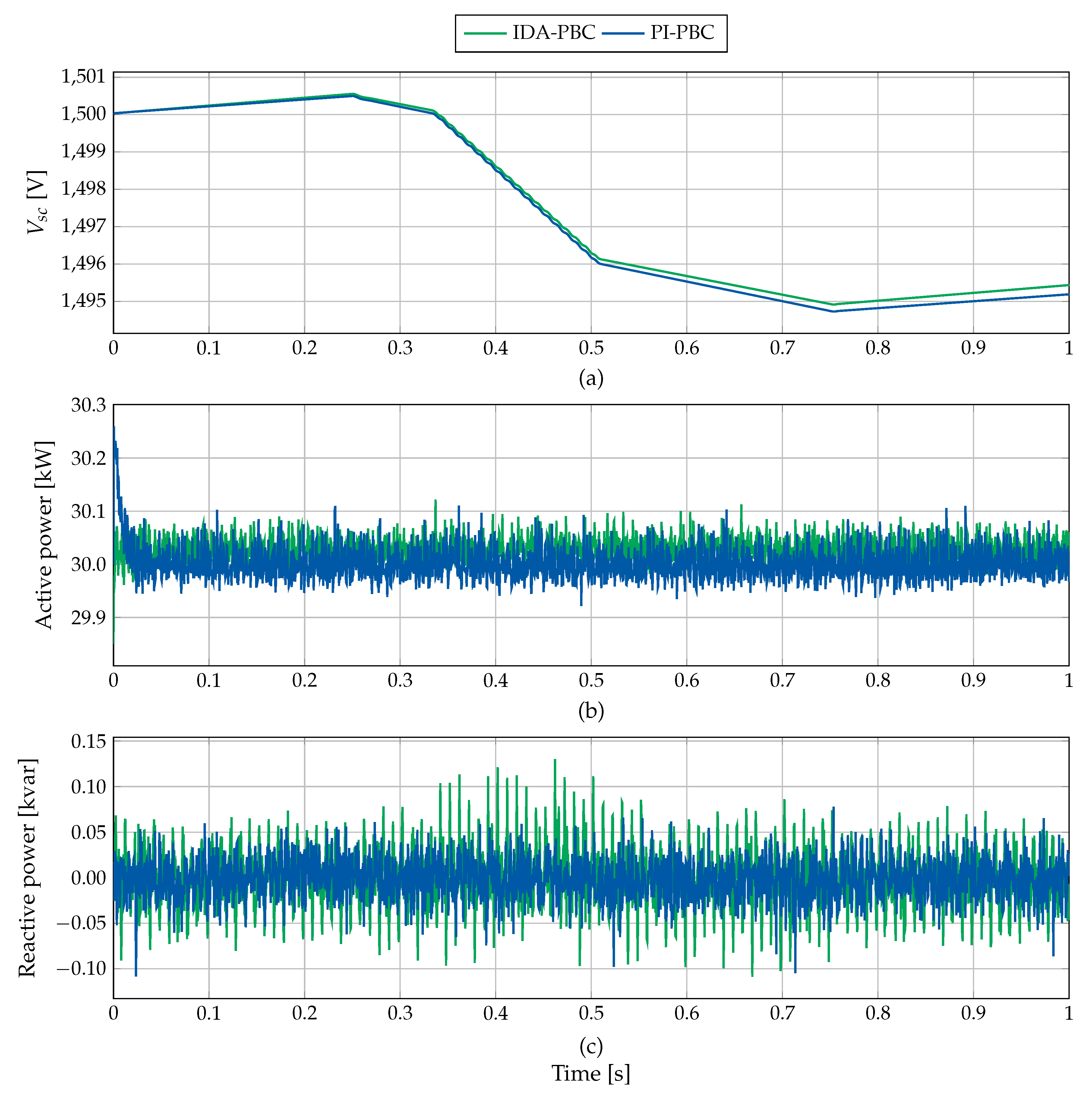
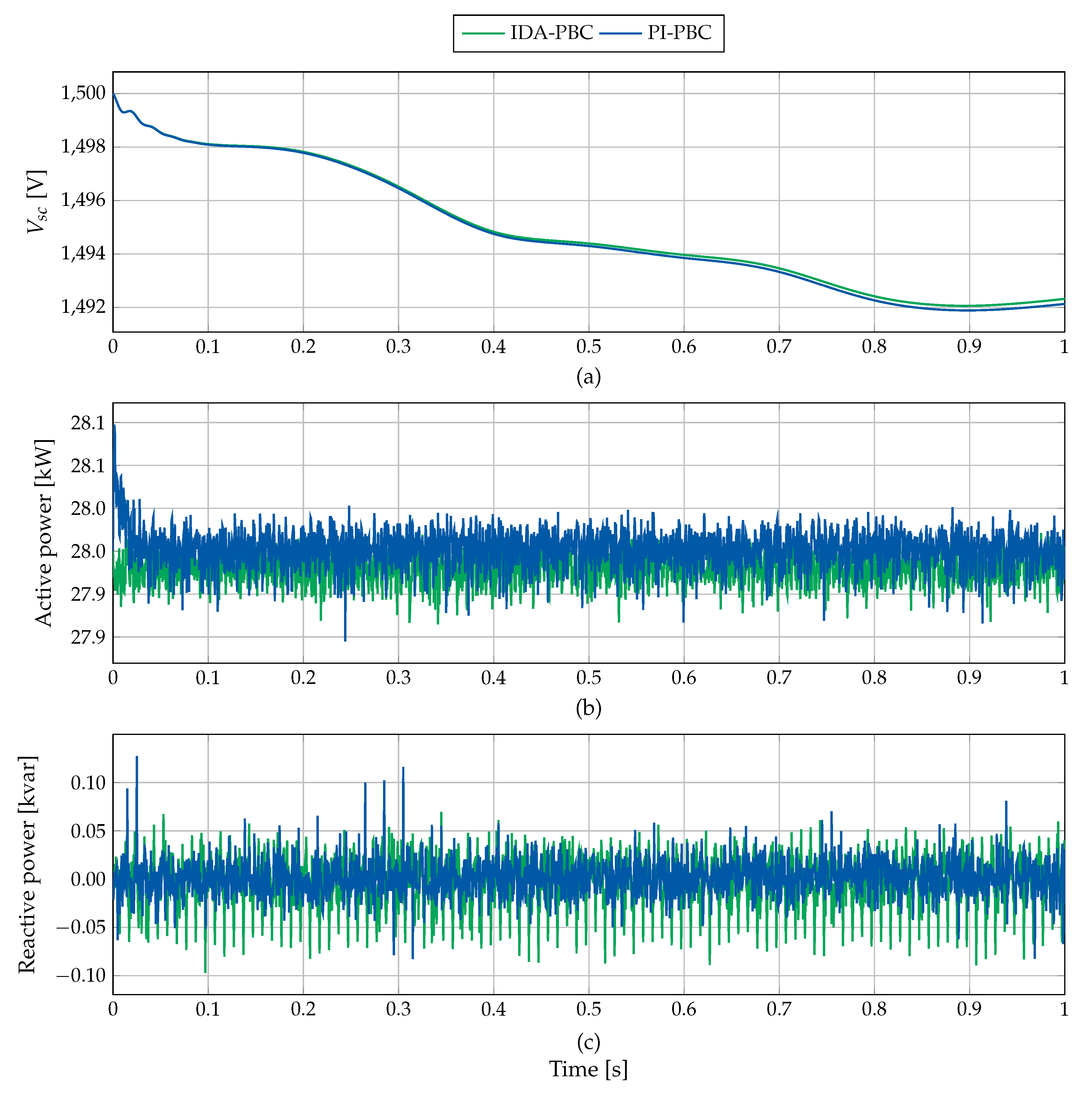
6.2. Scenario 2
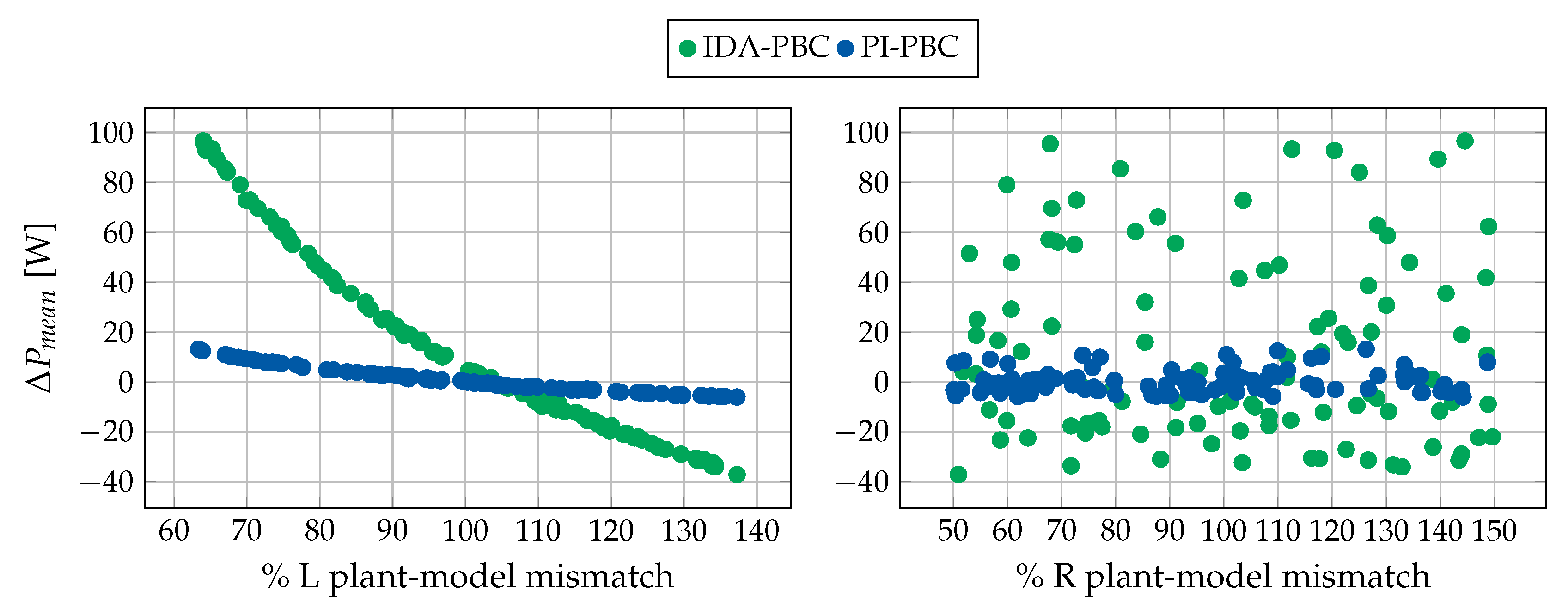
Complementary Analysis
7. Conclusions
Author Contributions
Acknowledgments
Conflicts of Interest
References
- Mensah-Darkwa, K.; Zequine, C.; Kahol, P.K.; Gupta, R.K. Supercapacitor energy storage device using biowastes: A sustainable approach to green energy. Sustainability 2019, 11, 414. [Google Scholar] [CrossRef]
- Gil, W.; Montoya, O.D.; Garces, A. Direct power control of electrical energy storage systems: A passivity-based PI approach. Electr. Power Syst. Res. 2019, 175, 105885. [Google Scholar]
- Montoya, O.D.; Garces, A.; Espinosa-Perez, G. A generalized passivity-based control approach for power compensation in distribution systems using electrical energy storage systems. J. Energy Storage 2018, 16, 259–268. [Google Scholar] [CrossRef]
- Aly, M.M.; Abdel-Akher, M.; Said, S.M.; Senjyu, T. A developed control strategy for mitigating wind power generation transients using superconducting magnetic energy storage with reactive power support. Int. J. Electr. Power Energy Syst. 2016, 83, 485–494. [Google Scholar] [CrossRef]
- Montoya, O.D.; Gil-González, W.; Garces, A. SCES Integration in Power Grids: A PBC Approach under abc, αβ0 and dq0 Reference Frames. In Proceedings of the 2018 IEEE PES Transmission & Distribution Conference and Exhibition-Latin America (T&D-LA), Lima, Peru, 18–21 September 2018; pp. 1–5. [Google Scholar]
- Haihua, Z.; Khambadkone, A.M. Hybrid modulation for dual active bridge bi-directional converter with extended power range for ultracapacitor application. In Proceedings of the 2008 IEEE Industry Applications Society Annual Meeting, Edmonton, AB, Canada, 5–9 October 2008; pp. 1–8. [Google Scholar]
- Gil-González, W.J.; Garcés, A.; Escobar, A. A generalized model and control for supermagnetic and supercapacitor energy storage. Ing. Cienc. 2017, 13, 147–171. [Google Scholar] [CrossRef]
- Thounthong, P.; Luksanasakul, A.; Koseeyaporn, P.; Davat, B. Intelligent model-based control of a standalone photovoltaic/fuel cell power plant with supercapacitor energy storage. IEEE Trans. Sustain. Energy 2012, 4, 240–249. [Google Scholar] [CrossRef]
- Mufti, M.D.; Iqbal, S.J.; Lone, S.A.; Ain, Q. Supervisory Adaptive Predictive Control Scheme for Supercapacitor Energy Storage System. IEEE Syst. J. 2015, 9, 1020–1030. [Google Scholar] [CrossRef]
- Montoya, O.D.; Gil-González, W.; Garces, A. Distributed energy resources integration in single-phase microgrids: An application of IDA-PBC and PI-PBC approaches. Int. J. Electr. Power Energy Syst. 2019, 112, 221–231. [Google Scholar] [CrossRef]
- Montoya, O.D.; Gil-González, W.; Avila-Becerril, S.; Garces, A.; Espinosa-Pérez, G. Distributed Energy Resources Integration in AC Grids: A Family of Passivity-Based Controll, (in Spanish). Rev. Iberoam. Autom. Inform. Ind. 2019, 16, 212–221. [Google Scholar] [CrossRef]
- Ortega, R.; Perez, J.A.L.; Nicklasson, P.J.; Sira-Ramirez, H.J. Passivity-Based Control of Euler-Lagrange Systems: Mechanical, Electrical and Electromechanical Applications; Springer Science & Business Media: Berlin/Heidelberg, Germany, 2013. [Google Scholar]
- van der Schaft, A. L2-Gain and Passivity Techniques in Nonlinear Control; Springer: Berlin/Heidelberg, Germany, 2017. [Google Scholar]
- Cisneros, R.; Pirro, M.; Bergna, G.; Ortega, R.; Ippoliti, G.; Molinas, M. Global tracking passivity-based PI control of bilinear systems: Application to the interleaved boost and modular multilevel converters. Control Eng. Pract. 2015, 43, 109–119. [Google Scholar] [CrossRef]
- Zonetti, D. Energy-Based Modelling and Control of Electric Power Systems with Guaranteed Stability Properties. Ph.D. Thesis, Université Paris-Saclay, Saint-Aubin, France, 2016. [Google Scholar]
- Zonetti, D.; Ortega, R.; Benchaib, A. A globally asymptotically stable decentralized PI controller for multi-terminal high-voltage DC transmission systems. In Proceedings of the 2014 European control conference (ECC), Strasbourg, France, 24–27 June 2014; pp. 1397–1403. [Google Scholar]
- Zonetti, D.; Ortega, R.; Benchaib, A. Modeling and control of HVDC transmission systems from theory to practice and back. Control. Eng. Pract. 2015, 45, 133–146. [Google Scholar] [CrossRef]
- Gil-González, W.; Montoya, O.D.; Garces, A. Direct power control for VSC-HVDC systems: An application of the global tracking passivity-based PI approach. Int. J. Electr. Power Energy Syst. 2019, 110, 588–597. [Google Scholar] [CrossRef]
- Montoya, O.D.; Gil-González, W.; Serra, F.M. PBC Approach for SMES Devices in Electric Distribution Networks. IEEE Trans. Circuits Syst. II Exp. Briefs 2018, 65, 2003–2007. [Google Scholar] [CrossRef]
- Harnefors, L.; Nee, H.P. Model-based current control of AC machines using the internal model control method. IEEE Trans. Ind. Appl. 1998, 34, 133–141. [Google Scholar] [CrossRef]
- IEEE Standard for Interconnecting Distributed Resources with Electric Power Systems—Amendment 1. In IEEE Std 1547a-2014 (Amendment to IEEE Std 1547-2003); IEEE: Piscataway, NJ, USA, 2014; pp. 1–16. [CrossRef]


| Scenario 1 | |||||
|---|---|---|---|---|---|
| [W] | [var] | [%] | |||
| IDA-PBC | 43.39 | 30.93 | 10.69 | 7.72 | 1.57 |
| PI-PBC | 23.71 | 20.65 | 5.94 | 5.35 | 1.55 |
| Scenario 2 with | |||||
| [W] | [var] | [%] | |||
| IDA-PBC | 28.26 | 23.79 | 7.01 | 5.98 | 0.99 |
| PI-PBC | 24.68 | 18.59 | 5.82 | 4.64 | 0.98 |
| Scenario 2 with | |||||
| [W] | [var] | [%] | |||
| IDA-PBC | 21.39 | 18.76 | 5.28 | 4.66 | 1.82 |
| PI-PBC | 18.38 | 14.60 | 4.36 | 3.63 | 1.80 |
© 2020 by the authors. Licensee MDPI, Basel, Switzerland. This article is an open access article distributed under the terms and conditions of the Creative Commons Attribution (CC BY) license (http://creativecommons.org/licenses/by/4.0/).
Share and Cite
Gil-González, W.; Martin Serra, F.; Montoya, O.D.; Ramírez, C.A.; Orozco-Henao, C. Direct Power Compensation in AC Distribution Networks with SCES Systems via PI-PBC Approach. Symmetry 2020, 12, 666. https://doi.org/10.3390/sym12040666
Gil-González W, Martin Serra F, Montoya OD, Ramírez CA, Orozco-Henao C. Direct Power Compensation in AC Distribution Networks with SCES Systems via PI-PBC Approach. Symmetry. 2020; 12(4):666. https://doi.org/10.3390/sym12040666
Chicago/Turabian StyleGil-González, Walter, Federico Martin Serra, Oscar Danilo Montoya, Carlos Alberto Ramírez, and César Orozco-Henao. 2020. "Direct Power Compensation in AC Distribution Networks with SCES Systems via PI-PBC Approach" Symmetry 12, no. 4: 666. https://doi.org/10.3390/sym12040666
APA StyleGil-González, W., Martin Serra, F., Montoya, O. D., Ramírez, C. A., & Orozco-Henao, C. (2020). Direct Power Compensation in AC Distribution Networks with SCES Systems via PI-PBC Approach. Symmetry, 12(4), 666. https://doi.org/10.3390/sym12040666