Article

Two New Asymmetric Boolean Chaos Oscillators with No Dependence on Incommensurate Time-Delays and Their Circuit Implementation

by
Jesus M. Munoz-Pacheco
,
Tonatiuh García-Chávez
,
Victor R. Gonzalez-Diaz
*,†,
Gisela de La Fuente-Cortes
and
Luz del Carmen Gómez-Pavón
Faculty of Electronics Sciences, Benemérita Universidad Autónoma de Puebla, Puebla 72000, Mexico
*
Author to whom correspondence should be addressed.
These authors contributed equally to this work.
Symmetry 2020, 12(4), 506; https://doi.org/10.3390/sym12040506
Submission received: 17 February 2020 / Revised: 4 March 2020 / Accepted: 7 March 2020 / Published: 1 April 2020
(This article belongs to the Special Issue Symmetry in Chaotic Systems and Circuits)

Abstract

:
This manuscript introduces two new chaotic oscillators based on autonomous Boolean networks (ABN), preserving asymmetrical logic functions. That means that the ABNs require a combination of XOR-XNOR logic functions. We demonstrate analytically that the two ABNs do not have fixed points, and therefore, can evolve to Boolean chaos. Using the Lyapunov exponent’s method, we also prove the chaotic behavior, generated by the proposed chaotic oscillators, is insensitive to incommensurate time-delays paths. As a result, they can be implemented using distinct electronic circuits. More specifically, logic-gates–, GAL–, and FPGA–based implementations verify the theoretical findings. An integrated circuit using a CMOS 180nm fabrication technology is also presented to get a compact chaos oscillator with relatively high-frequency. Dynamical behaviors of those implementations are analyzed using time-series, time-lag embedded attractors, frequency spectra, Poincaré maps, and Lyapunov exponents.

1. Introduction

Chaos behavior is one of the most studied topics in nonlinear dynamics in recent years. Such interest relies mainly on its extreme sensitivity to the initial conditions. From a real-world application point of view, the random-like patterns generated by chaotic oscillators are currently pointed out as the core for obtaining significant engineering applications, for instance, secure-communications schemes [1,2,3,4,5,6,7]; radars [8,9,10]; sonars [11,12]; liquid mixing [13,14]; adaptive logic gates [15,16]; true random number generators (TRNGs) [17,18]; collective phenomena in physics and biology [19,20]; navigation and control of autonomous mobile robots [21,22,23]; Internet of Things [24,25,26,27,28,29]; and so forth. Thereupon, the cutting edge chaos-based applications may need reliable, robust, compact, and faster chaos oscillators.
A remarkable solution to obtain chaotic behavior consists of exploiting the delay paths in autonomous Boolean networks (ABNs) [30,31,32,33,34]. Kauffman proposed the Boolean networks in 1969 as a mathematical framework for studying gene regulatory networks. The mathematics describing ABNs has shown that they could display aperiodic patterns if the Boolean functions have instantaneous response times, the link time-delays are incommensurate, and their nodes perform asymmetric Boolean operations, such as the combination of logic exclusive-OR (XOR) and XNOR functions.
In the context of ABNs, deterministic chaos, also known as Boolean chaos, was initially demonstrated by using Boolean functions implemented with electronic logic circuits (logic gates and field-programmable gate arrays FPGAs) [10,35,36,37,38]. At circuit level, the basic principle for obtaining Boolean chaos depends on three main characteristics; the asymmetry between the logic states, the short-pulse rejection phenomenon, and, most importantly, the degradation effect [30,31].
As is well-known, the incommensurate delay between two different nodes of an ABN is the critical parameter to obtain chaotic behaviors since it induces the degradation effect [30,31,32,33,34]. Rosin et al. analyzed two ABNs, one composed of a logic XOR function and two delays τ n k and τ n l , and the other one with a logic XNOR function and three delays τ n k , τ n l , and τ n m [38]. They showed that Boolean chaos arises in an FPGA-based implementation when the delays for each of the three delay paths are τ n k 2.8   n s , τ n l 1.7   n s , and τ n m 0.56   n s , respectively. To attain the time-delays, they required 18 extra logic NOT gates to connect the nodes of ABN. Besides, if those time-delays reduce below the minimum, the ABN does not show chaos and evolves to periodic oscillations only, as was analyzed in Ref. [35]. Park et al. presented an ABN composed of a logic XOR gate and ring oscillator [39]. The proposed logic circuit synthesized on an application-specific IC (ASIC), but the design is not straightforward because it also demands specific incommensurate delays in the feedback path to observe Boolean chaos.
Based on the discussion mentioned above, we note a possible benefit of using ABNs can be to get Boolean chaos oscillators with relatively high oscillation frequencies and small form factors since they depend on logic functions only. However, we also found that the proposed ABNs have high sensitivity to the time-delay among network nodes for generating chaos behavior. From a practical point of view, that condition is very complicated to satisfy since the time-delays are heavily related to the electronics technology chosen for implementation. Due to the electronic logic gates being heterogeneous, they do not have the same intrinsic time-delay. As a consequence, the dynamical behaviors of the ABN can be affected by placing the oscillator on a different area into an integrated circuit or FPGA. In conclusion, the previously reported Boolean chaos oscillators may not be suitable for physical realizations with multiple hardware approaches.
In this paper, we propose two ABNs with three and two nodes, respectively. The nodes perform the logic XOR and XNOR operations. This asymmetric approach avoids fixed points in the ABNs, and therefore, their dynamics can converge to chaotic oscillations. By applying the Lyapunov exponent method, we experimentally demonstrate that the Boolean chaos oscillators do not require specific incommensurate time-delays to show chaotic behaviors. Indeed, the Boolean chaos was observed under a wide range of the time-delays for the ABNs nodes. We prove our findings by implementing the proposed ABNs using various logic electronic circuits without any modification neither of the proposed networks nor adding additional path delays. Three discrete physical realizations using commercial logic gates, a Generic Array Logic (GAL), and FPGA are presented. Besides, we design an integrated circuit realization at 180nm fabrication technology.
The structure of the manuscript is as follows. Section 2 introduces the two ABNs and gives the mathematical demonstrations of their equilibrium points. Section 3 shows the analysis based on the Lyapunov exponents to determine the insensibility to time-delays. Section 4 presents the Lyapunov exponents for three different discrete implementations to prove that the ABNs are not affected by the technology. Section 5 introduces a straightforward methodology to design an integrated circuit of the Boolean chaos oscillators. Time-series, phase space reconstruction, Lyapunov exponents, and Poincare maps validate the observed chaos behavior. Finally, the last section concludes the paper.

2. Mathematical Preliminaries

A Boolean network consists of a number of logical nodes interconnected through direct or indirect links. These are nonlinear networks requiring a mathematical base for analysis. Among the present models there are: the Kauffman (N-K) networks, Boolean differential equations, and piecewise-linear differential equations [33,34]. This work uses the Boolean differential equations to develop important mathematical considerations.

2.1. Boolean Differential Equations

Let us consider a system with state variables { v 1 , v 2 , , v n }, v i R , i = 1 , , n . If a Boolean variable x i is related to each state v i , depending on a set of thresholds σ i R . Then, the set of Boolean variables x = { x 1 , x 2 , , x n } gives a simple qualitative description of the system with 2 n possible states. By adding the time dependence through a set of delays { τ i j } , i = 1 , , n , j = 1 , , n , τ i j > 0 , where τ i j is the time it takes for x j to affect x i , there is an associated time delay for each pair of state variables not necessarily obeying τ i j = τ j i . In this manner, the feedbacks among the Boolean variables can be described by a system of Boolean differential equations as follows [33,34]:
x 1 ( t ) = f 1 ( x 1 ( t τ 11 ) , x 2 ( t τ 12 ) , , x n ( t τ 1 n ) ) , x 2 ( t ) = f 2 ( x 1 ( t τ 21 ) , x 2 ( t τ 22 ) , , x n ( t τ 2 n ) ) , x n ( t ) = f n ( x 1 ( t τ n 1 ) , x 2 ( t τ n 2 ) , , x n ( t τ n n ) ) ,
with f i : B n B , i = 1 , , n , being a set of Boolean functions where B = { 0 , 1 } . The system (1) determines the dynamics of a Boolean network considering time delays, thereby defining an Autonomous Boolean Network (ABN) [33,34]. The dynamics of the ABN given by Equation (1) is numerically solved once the Boolean functions are defined with initial conditions on an interval x i ( t ) = x i 0 ( t ) for t 0 τ t t 0 , i = 1 , , n , where τ = max { τ i j } is the memory length of the system.

2.2. Boolean Chaos

In an ideal ABN, the transitions of the signals are arbitrarily fast and the number of transitions increases with time, following a power law. These increasingly fast dynamics result in an unlimited growth of frequency over time, referred to as an ultraviolet catastrophe [30]. However, that phenomenon does not occur in nature because the information-transmitting links and the processing nodes (for instance real logic gates) have a maximum operation frequency, which are physically realized. Hence, they cannot transmit or generate signals above a certain frequency [31]. As a result, the nonideal behaviors of real logic devices are responsible for the origin of chaos in ABNs [30,31]. Those behaviors are (i) Short-pulse rejection (SPR), known as pulse filtering, preventing pulses shorter than a minimum duration from passing through the gate (Theorem 1). (ii) The asymmetry between the logic states, making the propagation delay time through the gate depending on whether the transition is a fall or rise. (iii) The degradation effect triggering a change in the events propagation delay time when they appear in rapid succession. Among them, the degradation effect is the main nonideal behavior source of deterministic chaos in an ABN [32], since Boolean chaos originates from a history-dependent delay [30,31], as defined Lemma 1.
Theorem 1.
For a symmetric ABN consisting of a single XOR logic operation with two self-inputs having delays τ 1 and τ 1 , and with τ s p r sufficiently small not collapsing to the always-off state occurs before t = τ 2 , the trajectory will never reach the always-off state.
Lemma 1.
For a class of experimental ABN containing at least one XOR connective and feedback loop, deterministic chaos may arise if and only if the degradation effect, which is exhibited at some level in any real ABN, is presented.
On the other hand, if the ABN has equal delays, the links will produce only regular oscillations. In addition, the fixed points caused by using only symmetric logic functions in the network nodes conduct that the dynamics will always collapse into a low or high logic state, respectively. Theorem 2 and Lemma 2 postulates the conditions. As a reference, the complete proofs of Theorems and Lemmas can be found in [31,35].
Theorem 2.
For a symmetric ABN consisting of a single exclusive-OR (XOR) logic operation with two self-inputs having delays τ 1 and τ 2 , the attractors are always periodic.
Lemma 2.
The experimentally realized ABNs should not include a Boolean fixed point, for which all Boolean functions are satisfied simultaneously.

2.3. Lyapunov Exponents for ABNs

One of the most reliable tools to demonstrate chaotic behavior is computing the Lyapunov exponent’s spectrum [1,2,3,4,5,6,7,8,9,10,11,12,13,14,15,16,17,18,19,20,21,22,23,24,25,26,27,28,29]. A positive Lyapunov exponent is a signature of chaos [40]. It is defined as the exponential divergence of trajectories with nearly identical initial conditions. For the ABNs case, since the states are discrete, indicating a phase space composed just by 2 N states, the Lyapunov exponent’s needs to be computed from distance measures tailored for Boolean systems [41].
Zhang et al. proposed a method to estimate the largest Lyapunov exponent using the Boolean distance definition [30]. The approach works as follows. (i) Acquire experimentally a long time series from an output voltage of the ABN. (ii) Convert that voltage to a Boolean variable x ( t ) . (iii) Given any two segments of starting at times t a and t b , define a Boolean distance with d ( s ) = 1 T s s + T x ( t + t a ) x ( t + t b ) d t , where T is a fixed parameter, ⊕ is the XOR logic operation, and the Boolean distance d ( s ) evolves as a function of the time s. (iv) Search in x ( t ) for all the pairs t a and t b corresponding to the earliest times in each interval T over which d ( 0 ) < 0.01 . v. Finally, v ) compute ln d ( s ) , where means an average over all matching ( t a , t b ) pairs.
As a conclusion, the divergence ln d ( s ) increases exponentially, as expected for an adequate definition of distance between trajectories in a chaotic system [40].

3. The Proposed Boolean Chaos Oscillators (BCOs) and Their Fixed Points
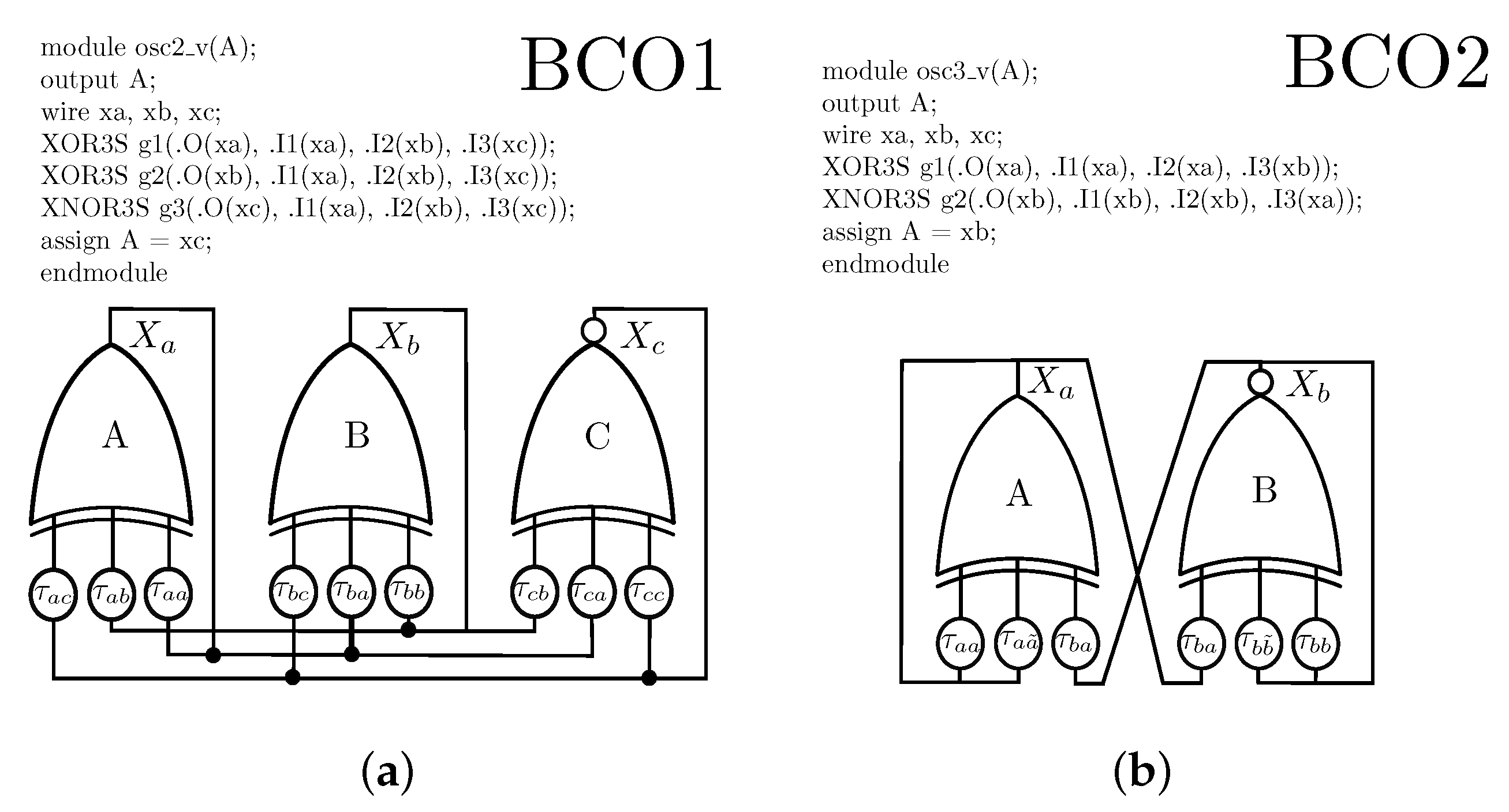
Motivated by Ref. [30], this work introduces two ABNs composed by three and two nodes, respectively. The nodes of ABNs perform asymmetric logic functions, i.e., a combination of Boolean operations XOR and XNOR. We detail the proposed ABNs as follows.

3.1. BCO-1

Figure 1a shows the first Boolean chaos oscillator (BCO). It consists of three nodes where each node has three inputs and one output that propagates to three different nodes. Nodes A and B perform the XOR logic operation while node C executes the XNOR. Expressing BCO-1 in the form of Equation (1), we obtain the following system of Boolean delay equations:
X a ( t ) = X a ( t τ a a ) X b ( t τ a b ) X c ( t τ a c ) , X b ( t ) = X a ( t τ b a ) X b ( t τ b b ) X c ( t τ b c ) , X c ( t ) = X a ( t τ c a ) X b ( t τ c b ) X c ( t τ c c ) 1 ,
with Boolean functions f i : B 3 B , i = 1 , , 3 , and ⊕ the logic XOR operation. The signal propagation time from node j to node i is τ i j for i , j = a , b , c .
Theorem 3.
For an autonomous Boolean network given by the system of Equation (2), the orbits are always oscillating [36].
Proof. 
A Boolean fixed point provokes nonoscillating dynamics due to some orbits eventually collapsing into the fixed point. To demonstrate the proposed Boolean chaos oscillator converges to sustained oscillations indefinitely, we must prove that there is not a fixed point. By contradiction, we demonstrate this theorem. Let us assume that the BCO-1 has a fixed point ( X a * , X b * , X c * ) , such that:
X a * = X a ( t τ ) , X b * = X b ( t τ ) , X c * = X c ( t τ ) ,
for t τ = max { τ a a , τ a b , τ a c , τ b a , τ b b , τ b c , τ c a , τ c b , τ c c } . In this manner, the system of Equation (2) recast as:
X a ( t ) = X a ( t ) X b ( t ) X c ( t ) ,
X b ( t ) = X a ( t ) X b ( t ) X c ( t ) ,
X c ( t ) = X a ( t ) X b ( t ) X c ( t ) 1 .
By substituting Equations (3) and (4) into (5), we obtain:
X c ( t ) = X a ( t ) X b ( t ) X c ( t ) X a ( t ) X b ( t ) X c ( t ) X c ( t ) 1 .
Equation (6) implies X c ( t ) = X c ( t ) ¯ . Since the Boolean space is 2 n , the possible states for X c ( t ) are { 1 , 0 } . Thus, “1” = “0”, or vice-versa indicates a contradiction which leads us to conclude that Boolean network (2) does not have fixed points, and therefore, always oscillates. □

3.2. BCO-2

Figure 2a shows the second Boolean chaos oscillator introduced in this work. The proposed topology consists of two nodes, where each node has three inputs and one output connecting to two different nodes. While node A performs the XOR logic operation, node B executes the XNOR. Additionally, the ABN includes two logic NOT operations to obtain the opposed Boolean states for both nodes. The set of Boolean delay equations for the BCO-2 are:
X a ( t ) = X a ( t τ a a ) X b ( t τ a b ) ¬ X a ( t τ a a ˜ ) , X b ( t ) = X a ( t τ b a ) X b ( t τ b b ) ¬ X b ( t τ b b ˜ ) 1 ,
with ⊕ and ¬ indicating the logic XOR and NOT operations, respectively. In addition, the Boolean functions f i : B 2 B , i = 1 , , 2 . Similarly to the previous case, it is necessary to prove that the system (7) does not have a Boolean fixed point.
Theorem 4.
For an autonomous Boolean network given by the system of Equation (7), the orbits are always oscillating [36].
Proof. 
We assume that the BCO-2 has the fixed point ( X a * , X b * ) , such that X a * = X a ( t τ ) and X b * = X b ( t τ ) , for t τ = m a x { τ a a , τ a b , τ a a ˜ , τ b a , τ b b , τ b b ˜ } . Therefore, system (7) is rewritten as:
X a ( t ) = X a ( t ) X b ( t ) ¬ X a ( t ) ,
X b ( t ) = X a ( t ) X b ( t ) ¬ X b ( t ) 1 ,
By inserting Equation (8) into (9), we obtain:
X b ( t ) = X a ( t ) X b ( t ) ¬ X a ( t ) X b ( t ) ¬ X b ( t ) 1 .
Equation (10) means X b ( t ) = X b ( t ) ¯ . This again implies a contradiction and it is possible to claim that the autonomous Boolean network (7) does not have a fixed point and it will oscillate permanently. □

3.3. Boolean Sensitivity Caused by Asymmetric Logic Functions

As demonstrated in the previous subsection, the presented BCOs do not have fixed points. In this manner, when an autonomous Boolean network is realized experimentally it should include asymmetric Boolean functions to achieve chaotic dynamics [31,35]. As a result, the preference for using logic XOR and XNOR functions in the proposed BCOs lies on the look-up table for these logic operations. Firstly, the idea is considering an equal number of “1”s and “0”s as the output of the XNOR operation to avoid converging into a physical Boolean fixed-point, i.e., where all entries of the look-up table have the same value, and hence inputs and outputs can be the same. From the look-up tables in Figure 1b and Figure 2b, the outputs are different for all inputs, including the cases “000” and “111”. On the other hand, since the number of “0”s and “1”s in the look-up tables is equal, the proposed BCOs can have a higher Boolean sensitivity E = 2 K ρ ( 1 ρ ) [30,35]. This is possible with randomly chosen Boolean functions of bias ρ = 0.5 (equal number of zeros and ones) and high in-degree K (the number of input connections to a node) or most effectively by using XOR and XNOR Boolean functions as herein.

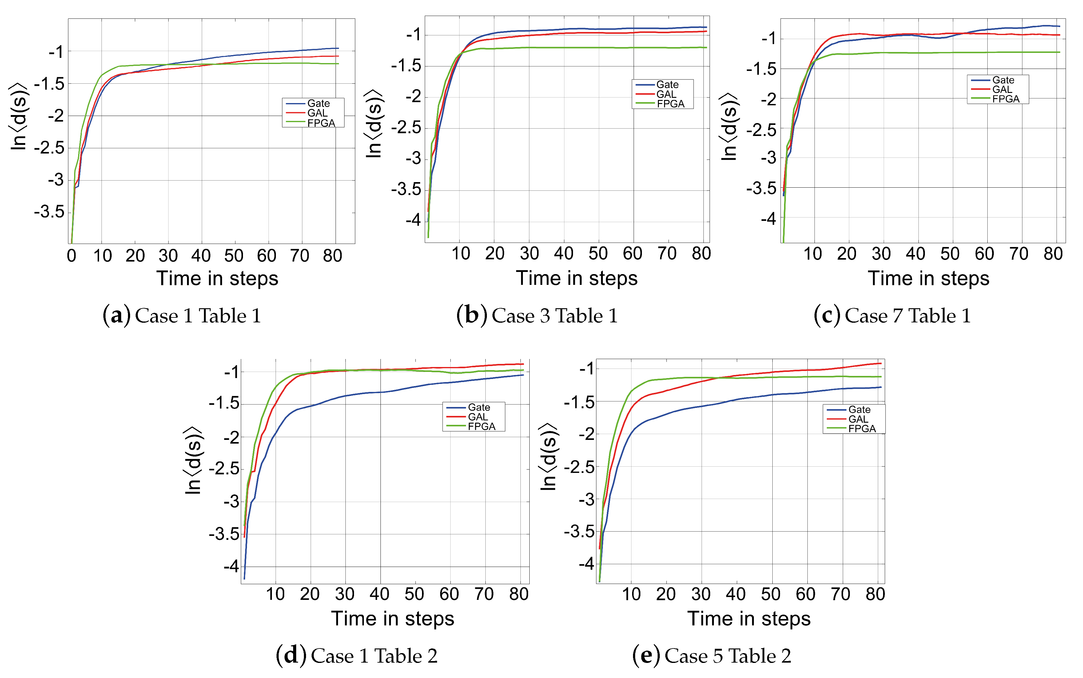
4. Boolean Chaos Robust to Different Incommensurate Time-Delays

The chaos-based applications demand the exploration of different typologies and implementations to find those that are the most suitable. In addition, the chaotic behavior must be robust. It means that the chaos should be generated consistently for a wide range of parameter values. In the ongoing literature, the reported autonomous Boolean networks only show chaos in certain ranges of the feedback delays [10,30,31,35,36,37,38,39], as was discussed in the Introduction section. At the experimental level, those approaches incorporate an even number of logic NOT gates in the link to act as a time-delay buffer to add extra signal propagation times. Then, the published works need several pairs of NOT gates to satisfy the specific incommensurate time-delays for each one of their links connecting nodes. Otherwise, the chaotic behavior converges to either periodic oscillations or stable dynamics in the Boolean levels high or low.
Conversely, the proposed BCOs in Figure 1 and Figure 2 do not require additional logic NOT gates to generate chaotic oscillations. This means that the chaos behavior depends solely on the incommensurate time-delays, arising only from the intrinsic delay associated with each XOR and XNOR gate. In this manner, we state the following Lemma and Corollary.
Lemma 3.
The Boolean chaotic oscillators of Figure 1 and Figure 2 composed only by logic XOR-XNOR functions evolve to sustained chaotic oscillations not only for different time-delays of the feedback path (additional pairs of logic NOT gates) but also when the time-delays in their links are a function just of the intrinsic delay of each XOR-XNOR gates (no extra logic NOT gates).
Corollary 1.
As a consequence of Theorems 3 and 4, an autonomous Boolean network without fixed points always presents periodic behavior if its delays are commensurate.
Proof. 
To demonstrate Lemma 3 and Corollary 1, we show the physical implementation of the BCOs in Figure 1 and Figure 2 using commercial off-the-shelf logic gates (74HCXXX family), as shown in Figure 3a. The discrete implementation makes it possible to change the time-delay between feedback nodes easily. Then, we study the dynamics of the proposed BCOs using the Lyapunov exponent method.
The scenario is as follows. First, we consider different cases for the incommensurate time-delays of the links. Those time-delays were realized using a pair of two NOT gates wired in series. Thus, from the experimental output signal of nodes C (BCO-1) and B (BCO-2) for each case in Table 1 and Table 2, respectively, we collect a long enough time series. For instance, the BCO-1 output signal of node C for cases 1, 3, and 7 is given in Figure 4a,d,g, respectively. On the other hand, Figure 5a,d present the results for the output signal of node B of BCO-2 for cases 1 and 5, respectively.
Next, we compute the largest Lyapunov exponent, λ m a x , applying the Boolean distance algorithm introduced in Section 2.3. The results in Table 1 and Table 2 shows the largest Lyapunov exponent, λ m a x , is positive for all cases indicating the proposed BCOs generate robust Boolean chaos. Besides, the chaotic behavior was also verified in the BCOs (both cases 1 in Table 1 and Table 2, respectively), without extra time-delays with exception from those incommensurate intrinsic delays of the logic XOR and XNOR gates, i.e., the BCO-1 and BCO-2 do not include any logic NOT gates in the feedback paths. □
Table 1 and Table 2 suggest the most suitable case for obtaining Boolean chaos is when no other delay paths are incorporated in the links because the higher the time-delays, the lower the magnitude of the largest Lyapunov exponent. From the physical implementation point of view, that is a remarkable feature because we can get a small form factor with the proposed Boolean chaos oscillators. Moreover, since the chaos generation does not depend on determined time-delays, the proposed BCOs can be implemented with several hardware technologies, as demonstrated in the next subsection.

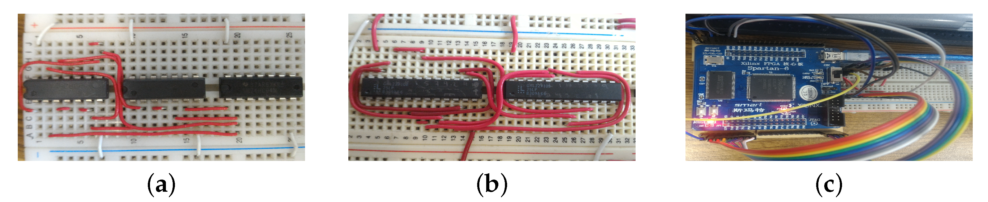
Boolean Chaos Robust to Distinct Discrete Physical Implementation

This subsection presents three different physical implementations of the Boolean chaos oscillators. The dynamics are affected by physical constraints and hardware differences. This may lead to time-delay variations where the boolean chaos displays. Therefore, the BCO-1 and BCO-2 are constructed with three different electronic devices (i) commercial-off-the-shelf logic gates (introduced previously), (ii) a GAL, and (iii) an FPGA. The experiments in Figure 3 demonstrate the robust generation of Boolean chaos. From the circuit conception, the implementations show the chaotic behavior source is the degradation effect [32]. In addition, there are no additional procedures to calculate the delay paths to achieve chaotic oscillations.
The implementation considers all cases of Table 1 and Table 2, but for the sake of simplicity, the Table 3 displays only the examples where the largest Lyapunov exponent is higher. In particular, case 1 for both BCOs is of particular interest because they do not need extra time-delays for generating chaos. More specifically, we use the GAL22V10 for realizing both BCOs, as given in Figure 3b. The programming of the GAL was performed with VHDL language. Figure 4b,e,h give the experimental results for the cases 1, 3, and 7 of BCO-1; while Figure 5b,e shows the results for cases 1 and 5 of BCO-2. For FPGA implementation, the Spartan 6 was employed (Figure 3c). The experimental results are shown in Figure 4c,f,i for cases 1, 3, 7 in Table 1, respectively. Figure 5c,f display the output signal for cases 1 and 5 in Table 2, respectively.
The measurements exhibit a 100 ns of time and a 2V of voltage grid per square. For all the three presented implementations, the output voltages (Figure 4 and Figure 5) show the cumbersome temporal oscillations without evident periodicity. This continuous-time evolution can be identified as Boolean chaos. To verify the chaotic behavior, we compute the largest Lyapunov exponent for each implemented case of the corresponding technology, as shown in Figure 6. Table 3 also shows that the Lyapunov exponents for the three physical implementations have a similar value. This behavior suggests the Boolean chaos of proposed BCOs is robust to the distinct physical implementations changing the technology.
It is worth to noting that, although the intrinsic time-delays of the logic XOR and XNOR gates change among the physical realizations, Case-1 for both BCOs continues generating chaotic behavior. In agreement with Lemma 4, the fact that there is Boolean chaos, for various implementations without extra time-delays in the feedback links, demonstrates that the proposed BCOs are not overly sensitive to heterogeneous intrinsic time-delays.

5. An Application Specific Integrated Circuit for the Proposed Boolean Chaos Oscillators
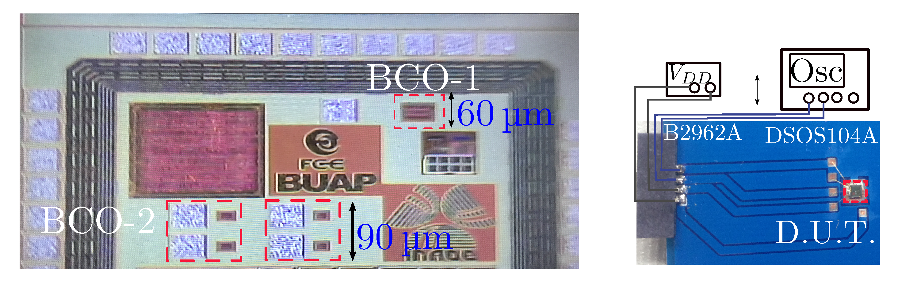
5.1. Chip Design

This section describes the integrated circuit-based implementation of the prospected BCOs in this work. The Boolean chaos generators are described with Verilog, a Hardware Description Language (HDL), using the UMC 180 nm Generic Core Cell Library. The BCO-1 hardware description in Figure 7a uses one XNOR3S and two XOR3S cells from the Generic Core library. That verilogHDL code synthesizes the three logic gates, whereas the Encounter tool (from Cadence Design Systems) executes a generic routing algorithm. Similarly, the BCO-2 of Figure 7b uses one XOR3S and one XNOR3S for the description with the verilogHDL code. The integrated circuit was part of a multiprocess wafer run and is shown in Figure 8 (Left). The size of BCO-1 is 75   μ m × 60   μ m while the BCO-2 has physical dimensions of 32   μ m × 26   μ m . The area for biasing rails is considered in both scenarios. In any case, it is possible to reduce the size with routing optimization.
It is worth noting that the design process of the IC is straightforward, and it does not depend on critical design considerations. However, all the design processes were executed in a semiautomated way using the generic cells and routing tool from Cadence software and UMC 180 nm fabrication technology. Therefore, this demonstrates, once again, the flexibility and robustness of the proposed BCOs.
On the other hand, Figure 8 (Right) shows the test-bench for the integrated circuit. The chip-die is mounted on an FR4 printed circuit board. It is biased with a low-noise V D D = 1.8   V voltage source model B2962A while the oscilloscope DSOS104A captures the voltage time-series for further analysis.

5.2. Experimental Results of the Integrated BCO-1 and BCO-2

Now, we present the continuous-time behavior of both BCO-1 and BCO-2 on the integrated circuit. Figure 9 shows the real-time obtained waveforms and the respective dynamical analysis considering: (i) time-series of the output voltage; (ii) frequency spectra; (iii) time-lag reconstructions of the attractors; (iv) Poincaré mapping set; (v) and largest Lyapunov exponent.
Figure 9a presents the BCO-1 features for V D D = 3.3 V. The time-series shows a random evolution since it has variable cycle amplitudes regarding maxima and minima, and the frequency content is characterized for a predominant broad distribution and with strong content up to 200 MHz, therefore suggesting chaotic oscillations. Besides, the time-lag embedded attractor (lag equal to the first minimum of the time-lag mutual information function) exhibits a chaotic behavior in phase space, whose underlying complexity can be more properly appreciated on the corresponding Poincaré map for amplitudes of successive local maxima. In this manner, the arbitrarily chosen plane sections the attractor in two and thereby enables the visualization of its complex geometry. We found that the Poincaré map has a dense set of points, which has been identified as characteristic dynamics of the chaotic behavior. To quantify these observations, we determine the largest Lyapunov exponent ( λ m a x ) of the attractor. The result shows the time evolution of the ln d ( s ) . This divergence presents an almost constant slope for the first part of the curve and then it saturates at a maximum value, corresponding to the uncorrelated signals x ( s + T + t a ) and x ( s + T + t b ) . Next, we estimate the value of λ m a x , assuming that the divergence of the initially similar segments is exponential in the region of constant slope. As a result, the average of all pairs of similar segments is our estimate of the largest Lyapunov exponent for the BCO-1, giving λ m a x = 0.4496 , which demonstrates that the CMOS Boolean oscillator integrated at 180 nm is chaotic.
Figure 9b shows the dynamical analysis for the same BCO-1 but now with V D D = 2.8 V. This BCO-1 displays a clear chaotic attractor in the 0–4 V range and is validated with the Poincaré set. The results for time-series, frequency spectrum up to 150 MHz, Poincaré map, and λ m a x = 0.4243 have a similar response to the previous case. Therefore, we can conclude the BCO-1 is robust against bias voltage variations.
The same test is included for the BCO-2 biased to VDD = 3.3 V. The circuit presents a chaotic oscillation but the on-chip pad originates an explicit limitation of the voltage swing. This prototype uses internal pad connections and the reduced swing is a consequence of the extended bonding and absence of I/O cells. Therefore, the on-die probes represent an important load impedance and limit output swing to 200 mV. Figure 9c shows the time evolution, spectral content up to 160 MHz, chaotic attractor, and Poincaré map showing the expected results. Finally, Figure 9c also shows the largest Lyapunov exponent, which has a slope less abrupt but still presents a positive exponent ( λ m a x = 0.2492 ) in spite of the small values of the continuous-time sequence.

5.3. Comparison with Similar Implementations

For the sake of reference, Table 4 highlights the principal features of the recent True Random Number Generator (TRNG), systems based on chaotic circuits. The two new boolean chaotic oscillators exhibit competitive numbers compared to the references [20,42]. The comparison includes the most recent works with attempts to fully integrate the system-on-chip. The work in [20] presents a set of inverted-based chaotic oscillators. The area and power consumption are affordable, but the system uses additional off-chip biasing circuits. The chaotic circuit in [42] is fully integrated with the disadvantage of increasing the circuit resources. This is the result of the multiattractor analog system requiring a large bandwidth but the band limitation or frequency centroid is not reported. The two new boolean chaotic oscillators in this work present a reduced circuit size and power dissipation, not considering the chip input-output cells. The proposed boolean chaotic circuits present the most extended frequency span content compared to the recent on-chip implementations.

6. Conclusions

Two autonomous Boolean networks that generate Boolean chaos have been introduced. From the mathematical model, it was shown that the logical states would never reach a fixed-point, and therefore, will oscillate permanently. The proposed Boolean chaos oscillators exhibited no dependence on incommensurate time-delays, as demonstrated by computing the Lyapunov exponents under various scenarios for the delay paths. The correct physical implementations of the two Boolean chaos oscillators are good evidence of the predicted conditions. Therefore, the BCOs are reliable and robust to be implemented with multiple circuit implementations, both discrete as integrated.
In particular, the synthesis of the chaotic oscillators in an integrated circuit has shown the benefits of a compact CMOS chaos generator with areas 0.0045 mm2 and 0.000832 mm2 for BCO-1 and BCO-2, respectively, as well as high-speed chaotic oscillations with relevant amplitude content up to 200 M Hz . Several dynamical analyses such as time-series, chaotic attractors, Poincaré maps, and Lyapunov exponents validated the experimental results.
In this manner, the proposed Boolean chaos oscillators could be useful for various engineering applications, for instance, random number generators, since the design is straightforward, robust, compact, and can be implemented in many options of hardware without needing special considerations.

Author Contributions

Conceptualization, J.M.M.-P. and T.G.-C.; methodology, J.M.M.-P. and V.R.G.-D.; software, J.M.M.-P., V.R.G.-D., G.d.L.F.-C.; validation, V.R.G.-D., T.G.-C. and G.d.L.F.-C.; formal analysis, J.M.M.-P.; investigation, J.M.M.-P., T.G.-C., and L.d.C.G.-P.; writing—original draft preparation, J.M.M.-P. and T.G.-C.; writing—review and editing, J.M.M.-P., V.R.G.-D., L.d.C.G.-P. All authors have read and agreed to the published version of the manuscript.

Funding

This research received no external funding.

Acknowledgments

J.M. Munoz-Pacheco acknowledges the National Council of Science and Technology (CONACYT) MEXICO for the financial support through Project No. 258880 (Proyecto Apoyado por el Fondo Sectorial de Investigacion para la Educacion). The Authors also thank CONACYT for the Lab project INFRA-2013-1-205873. The authors thankfully acknowledge computer resources, technical advice, and support provided by Laboratorio Nacional de Supercómputo del Sureste de México(LNS), a member of the CONACYT national laboratories, with project No. 202001025C.

Conflicts of Interest

The authors declare no conflict of interest.

References

  1. Yin, Q.; Wang, C. A new chaotic image encryption scheme using breadth-first search and dynamic diffusion. Int. J. Bifurc. Chaos 2018, 28, 1850047. [Google Scholar] [CrossRef]
  2. Kaddoum, G. Wireless chaos-based communication systems: A comprehensive survey. IEEE Access 2016, 4, 2621–2648. [Google Scholar] [CrossRef]
  3. Kocamaz, U.E.; Çiçek, S.; Uyaroğlu, Y. Secure communication with chaos and electronic circuit design using passivity-based synchronization. J. Circuits Syst. Comput. 2018, 27, 1850057. [Google Scholar] [CrossRef]
  4. Herceg, M.; Miličević, K.; Matić, T. Frequency-translated differential chaos shift keying for chaos-based communications. J. Frankl. Inst. 2016, 353, 2966–2979. [Google Scholar]
  5. Dmitriev, A.; Efremova, E.; Nikishov, A.Y. Generating dynamic microwave chaos in self-oscillating ring system based on complementary metal-oxide-semiconductor structure. Tech. Phys. Lett. 2010, 36, 430–432. [Google Scholar] [CrossRef]
  6. Herceg, M.; Vranješ, D.; Grbić, R.; Job, J. Chaos-Based transmitted-reference ultra-wideband communications. Int. J. Electron. 2019, 106, 160–172. [Google Scholar] [CrossRef]
  7. Gomez-Pavon, L.; Munoz-Pacheco, J.; Luis-Ramos, A. Synchronous Chaos Generation in an Er+3-Doped Fiber Laser System. IEEE Photonics J. 2015, 7, 1–6. [Google Scholar] [CrossRef]
  8. Liu, Z.; Zhu, X.; Hu, W.; Jiang, F. Principles of chaotic signal radar. Int. J. Bifurc. Chaos 2007, 17, 1735–1739. [Google Scholar] [CrossRef]
  9. Xu, H.; Li, L.; Li, Y.; Zhang, J.; Han, H.; Liu, L.; Li, J. Chaos-Based Through-Wall Life-Detection Radar. Int. J. Bifurc. Chaos 2019, 29, 1930020. [Google Scholar] [CrossRef]
  10. Qiao, J.; Xu, H.; Zhang, J.; Han, H.; Wang, B. High-resolution and anti-jamming chaotic guided radar prototype for perimeter intrusion detection. J. Electromagn. Waves Appl. 2019, 33, 1060–1069. [Google Scholar] [CrossRef]
  11. Fortuna, L.; Frasca, M.; Rizzo, A. Chaotic pulse position modulation to improve the efficiency of sonar sensors. IEEE Trans. Instrum. Meas. 2003, 52, 1809–1814. [Google Scholar] [CrossRef]
  12. Shin, S.; Kim, M.H.; Choi, S.B. Ultrasonic distance measurement method with crosstalk rejection at high measurement rate. IEEE Trans. Instrum. Meas. 2018, 68, 972–979. [Google Scholar] [CrossRef]
  13. Honglad, S.; San-Um, W. Automatic stand-alone liquid mixer with chaotic PWM control using diode-based Rössler system. In Proceedings of the IEEE 2014 International Electrical Engineering Congress (iEECON), Chonburi, Thailand, 19–21 March 2014; pp. 1–4. [Google Scholar]
  14. Xie, T.; Chen, M.; Xu, C.; Chen, J. High-throughput extraction and separation of Ce (III) and Pr (III) using a chaotic advection microextractor. Chem. Eng. J. 2019, 356, 382–392. [Google Scholar] [CrossRef]
  15. Murali, K.; Sinha, S.; Mohamed, I.R. Chaos computing: Experimental realization of NOR gate using a simple chaotic circuit. Phys. Lett. A 2005, 339, 39–44. [Google Scholar] [CrossRef]
  16. Kia, B.; Mobley, K.; Ditto, W.L. An integrated circuit design for a dynamics-based reconfigurable logic block. IEEE Trans. Circuits Syst. II Express Briefs 2017, 64, 715–719. [Google Scholar] [CrossRef]
  17. Wannaboon, C.; Tachibana, M.; San-Um, W. A 0.18-μm CMOS high-data-rate true random bit generator through ΔΣ modulation of chaotic jerk circuit signals. Chaos Interdiscip. J. Nonlinear Sci. 2018, 28, 063126. [Google Scholar] [CrossRef] [Green Version]
  18. Li, B.; Liao, X.; Jiang, Y. A novel image encryption scheme based on improved random number generator and its implementation. Nonlinear Dyn. 2019, 95, 1781–1805. [Google Scholar] [CrossRef]
  19. Minati, L. Experimental implementation of networked chaotic oscillators based on cross-coupled inverter rings in a CMOS integrated circuit. J. Circuits Syst. Comput. 2015, 24, 1550144. [Google Scholar] [CrossRef]
  20. Minati, L.; Frasca, M.; Yoshimura, N.; Ricci, L.; Oświecimka, P.; Koike, Y.; Masu, K.; Ito, H. Current-Starved Cross-Coupled CMOS Inverter Rings as Versatile Generators of Chaotic and Neural-Like Dynamics Over Multiple Frequency Decades. IEEE Access 2019, 7, 54638–54657. [Google Scholar] [CrossRef]
  21. Volos, C.K.; Kyprianidis, I.M.; Stouboulos, I.N. Experimental investigation on coverage performance of a chaotic autonomous mobile robot. Robot. Auton. Syst. 2013, 61, 1314–1322. [Google Scholar] [CrossRef]
  22. Petavratzis, E.K.; Volos, C.K.; Stouboulos, I.N.; Nistazakis, H.E.; Kyritsi, K.G.; Valavanis, K.P. Coverage Performance of a Chaotic Mobile Robot Using an Inverse Pheromone Model. In Proceedings of the IEEE 2019 8th International Conference on Modern Circuits and Systems Technologies (MOCAST), Thessaloniki, Greece, 13–15 May 2019; pp. 1–4. [Google Scholar]
  23. Ansari, U.; Bajodah, A.H.; Kada, B. Development and experimental investigation of a Quadrotor’s robust generalized dynamic inversion control system. Nonlinear Dyn. 2019, 96, 1541–1557. [Google Scholar] [CrossRef]
  24. Montero-Canela, R.; Zambrano-Serrano, E.; Tamariz-Flores, E.I.; Muñoz-Pacheco, J.M.; Torrealba-Meléndez, R. Fractional chaos based-cryptosystem for generating encryption keys in Ad Hoc networks. Ad Hoc Netw. 2020, 97, 102005. [Google Scholar] [CrossRef]
  25. Wang, T.; Wang, D.; Wu, K. Chaotic adaptive synchronization control and application in chaotic secure communication for industrial Internet of Things. IEEE Access 2018, 6, 8584–8590. [Google Scholar] [CrossRef]
  26. Mareca, P.; Bordel, B. Robust hardware-supported chaotic cryptosystems for streaming commutations among reduced computing power nodes. Analog Integr. Circuits Signal Process. 2019, 98, 11–26. [Google Scholar] [CrossRef]
  27. Muñoz-Pacheco, J.M.; Zambrano-Serrano, E.; Félix-Beltrán, O.; Gómez-Pavón, L.C.; Luis-Ramos, A. Synchronization of PWL function-based 2D and 3D multi-scroll chaotic systems. Nonlinear Dyn. 2012, 70, 1633–1643. [Google Scholar] [CrossRef]
  28. Flores-Vergara, A.; Garcia-Guerrero, E.; Inzunza-González, E.; López-Bonilla, O.; Rodríguez-Orozco, E.; Cardenas-Valdez, J.; Tlelo-Cuautle, E. Implementing a chaotic cryptosystem in a 64-bit embedded system by using multiple-precision arithmetic. Nonlinear Dyn. 2019, 96, 497–516. [Google Scholar] [CrossRef]
  29. Raza, S.F.; Satpute, V. A novel bit permutation-based image encryption algorithm. Nonlinear Dyn. 2019, 95, 859–873. [Google Scholar] [CrossRef]
  30. Zhang, R.; de S.Cavalcante, H.L.D.; Gao, Z.; Gauthier, D.J.; Socolar, J.E.S.; Adams, M.M.; Lathrop, D.P. Boolean chaos. Phys. Rev. E 2009, 80, 045202. [Google Scholar] [CrossRef] [Green Version]
  31. Cavalcante, H.L.; Gauthier, D.J.; Socolar, J.E.; Zhang, R. On the origin of chaos in autonomous Boolean networks. Philos. Trans. R. Soc. A Math. Phys. Eng. Sci. 2010, 368, 495–513. [Google Scholar] [CrossRef]
  32. Bellido-Diaz, M.; Juan-Chico, J.; Acosta, A.; Valencia, M.; Huertas, J. Logical modelling of delay degradation effect in static CMOS gates. IEE Proc. Circuits Devices Syst. 2000, 147, 107–117. [Google Scholar] [CrossRef]
  33. Ghil, M.; Mullhaupt, A. Boolean delay equations. II. Periodic and aperiodic solutions. J. Stat. Phys. 1985, 41, 125–173. [Google Scholar] [CrossRef]
  34. Dee, D.; Ghil, M. Boolean difference equations, I: Formulation and dynamic behavior. SIAM J. Appl. Math. 1984, 44, 111–126. [Google Scholar] [CrossRef]
  35. Rosin, D.P. Dynamics of Complex Autonomous Boolean Networks; Springer: Berlin, Germany, 2014. [Google Scholar]
  36. Rivera-Durón, R.R.; Campos-Cantón, E.; Campos-Cantón, I.; Gauthier, D.J. Forced synchronization of autonomous dynamical Boolean networks. Chaos Interdiscip. J. Nonlinear Sci. 2015, 25, 083113. [Google Scholar] [CrossRef] [PubMed]
  37. Rosin, D.P.; Rontani, D.; Gauthier, D.J. Ultrafast physical generation of random numbers using hybrid Boolean networks. Phys. Rev. E 2013, 87, 040902. [Google Scholar] [CrossRef] [Green Version]
  38. Rosin, D.P.; Rontani, D.; Gauthier, D.J.; Schöll, E. Experiments on autonomous Boolean networks. Chaos Interdiscip. J. Nonlinear Sci. 2013, 23, 025102. [Google Scholar] [CrossRef] [Green Version]
  39. Park, M.; Rodgers, J.C.; Lathrop, D.P. True random number generation using CMOS Boolean chaotic oscillator. Microelectron. J. 2015, 46, 1364–1370. [Google Scholar] [CrossRef]
  40. Wolf, A.; Swift, J.B.; Swinney, H.L.; Vastano, J.A. Determining Lyapunov exponents from a time series. Phys. D Nonlinear Phenom. 1985, 16, 285–317. [Google Scholar] [CrossRef] [Green Version]
  41. Luque, B.; Solé, R.V. Lyapunov exponents in random Boolean networks. Phys. A Stat. Mech. Appl. 2000, 284, 33–45. [Google Scholar] [CrossRef] [Green Version]
  42. Zhang, X.; Wang, C. A Novel Multi-Attractor Period Multi-Scroll Chaotic Integrated Circuit Based on CMOS Wide Adjustable CCCII. IEEE Access 2019, 7, 16336–16350. [Google Scholar] [CrossRef]
Figure 1. (a) Autonomous Boolean networks (ABN) for the proposed Boolean chaos oscillator (BCO-1). (b) An implementation of BCO-1 using electronic logic gates and its look-up table.
Symmetry 12 00506 g001
Figure 2. (a) ABN for the second Boolean chaos oscillator (BCO-2). (b) An implementation of BCO-2 using electronic logic gates and its look-up table.
Symmetry 12 00506 g002
Figure 3. Experimental setup for BCOs in Figure 1 and Figure 2 using (a) logic gates 74HCXXX, (b) GAL 22V10, and (c) FPGA Spartan6.
Symmetry 12 00506 g003
Figure 4. Chaotic oscillations from the output voltage in the node C for BCO-1. The measurements exhibit a 100 ns of time and a 2 V of voltage grid per square. Case 1 in Table 1 with (a) logic gates 74HCXXX, (b) GAL22V10, and (c) FPGA Spartan6. Case 3 in Table 1 with (d) logic gates 74HCXXX, (e) GAL22V10, and (f) FPGA Spartan6. Case 7 in Table 1 with (g) logic gates 74HCXXX, (h) GAL22V10, and (i) FPGA Spartan6.
Symmetry 12 00506 g004
Figure 5. Chaotic oscillations from the output voltage in the node B for BCO-2. The measurements exhibit a 100 ns of time and a 2 V of voltage grid per square. Case 1 in Table 2 with (a) logic gates 74HCXXX, (b) GAL22V10, and (c) FPGA Spartan6. Case 5 in Table 2 with (d) logic gates 74HCXXX, (e) GAL22V10, and (f) FPGA Spartan6.
Symmetry 12 00506 g005
Figure 6. The divergence ln d ( s ) to determine the largest Lyapunov exponent of the attractor for cases in Table 3 from each discrete physical implementation (Logic gates, GAL, FPGA).
Symmetry 12 00506 g006
Figure 7. (a) Synthesis codes in VerilogHDL for (a) BCO-1, and (b) BCO-2, respectively.
Symmetry 12 00506 g007
Figure 8. Microphotography of the chip and the test-bench for the integrated circuit.
Symmetry 12 00506 g008
Figure 9. Chaotic dynamics measured experimentally from the integrated circuit of 180 nm at distinct settings for both Boolean chaos oscillators. Top to bottom: Time-series, time-lag embedded attractor, frequency spectrum, Poincaré map, the divergence ln d ( s ) to determine the largest Lyapunov exponent λ m a x of the attractor. (a) Experimental results for BCO-1 @ V D D = 3.3 V with λ m a x = 0.4496; (b) Experimental results for BCO-1 @ V D D = 2.8 V with λ m a x = 0.4243; (c) Experimental results for BCO-2 @ V D D = 3.3 V with λ m a x = 0.2492.
Symmetry 12 00506 g009
Table 1. Largest Lyapunov exponent ( λ m a x ) of the BCO in Figure 1 for different time-delays in the feedback paths. The symbol “-” means no extra time-delay, while “√” refers to a time-delay composed of two logic NOT gates.
CaseTime-DelayLyapunov Exponent
τ a a τ a b τ a c τ b a τ b b τ b c τ c a τ c b τ c c λ m a x
1---------0.2306
2--------0.2079
3--------0.2275
4-------0.2057
5------0.2076
6------0.2101
7------0.2121
8---0.1774
9---0.1808
100.1896
11-0.1862
12--0.1707
Table 2. Lyapunov exponent of BCO in Figure 2 for different time-delays in the feedback paths.
CaseTime-DelayLyapunov Exponent
τ a a τ a b τ a a ˜ τ b b τ b a τ b b ˜ λ m a x
1------0.1644
2-----0.0960
3-----0.1495
4----0.1442
5-----0.1525
6-----0.1448
Table 3. Largest Lyapunov exponent ( λ m a x ) for BCOs in Figure 1 and Figure 2 implemented experimentally with different design technologies considering the time-delays of Table 1 and Table 2.
Logic GatesGALFPGA
BCO-1
λ m a x (case 1, Table 1)0.2300.2240.209
λ m a x (case 3, Table 1)0.2270.2210.194
λ m a x (case 7, Table 1)0.2120.2110.185
BCO-2
λ m a x (case 1, Table 2)0.1640.1600.157
λ m a x (case 5, Table 2)0.1520.1500.148
Table 4. Comparison of the principal features of recent TRNG based on chaotic systems.
This Work BCO-1This Work BCO-2[20][42]
Chaos sourceBoolean chaosBoolean chaosChaotic oscillationMultiattractor
IntegratedFullyFullyPartiallyFully
Technology180 nm180 nm180 nm180 nm
Size ( μ m ) 2 450083228,000(315,000 × 383,000)
Static power ( μ w ) 0.20.09253660
Speed limit ( M H z ) 20016010NA

