Article

Analysis Exploring the Uniformity of Flow Distribution in Multi-Channels for the Application of Printed Circuit Heat Exchangers

1
Science and Technology on Thermal Energy and Power Laboratory, Wuhan Second Ship Design and Resource Institute, Wuhan 430205, China
2
China-UK Low Carbon College, Shanghai Jiao Tong University, Shanghai 200240, China
*
Author to whom correspondence should be addressed.
Symmetry 2020, 12(2), 314; https://doi.org/10.3390/sym12020314
Submission received: 22 December 2019 / Revised: 21 January 2020 / Accepted: 6 February 2020 / Published: 22 February 2020
(This article belongs to the Special Issue Recent Advances in Mathematical Aspect in Engineering)

Abstract

:
The maldistribution of fluid flow through multi-channels is a critical issue encountered in many areas, such as multi-channel heat exchangers, electronic device cooling, refrigeration and cryogenic devices, air separation and the petrochemical industry. In this paper, the uniformity of flow distribution in a printed circuit heat exchanger (PCHE) is investigated. The flow distribution and resistance characteristics of a PCHE plate are studied with numerical models under different flow distribution cases. The results show that the sudden change in the angle of the fluid at the inlet of the channel can be greatly reduced by using a spreader plate with an equal inner and outer radius. The flow separation of the fluid at the inlet of the channel can also be weakened and the imbalance of flow distribution in the channel can be reduced. Therefore, the flow uniformity can be improved and the pressure loss between the inlet and outlet of PCHEs can be reduced. The flow maldistribution in each PCHE channel can be reduced to ± 0.2%, and the average flow maldistribution in all PCHE channels can be reduced to less than 5% when the number of manifolds reaches nine. The numerical simulation of fluid flow distribution can provide guidance for the subsequent research and the design and development of multi-channel heat exchangers. In summary, the symmetry of the fluid flow in multi-channels for PCHE was analyzed in this work. This work presents the frequently encountered problem of maldistribution of fluid flow in engineering, and the performance promotion leads to symmetrical aspects in both the structure and the physical process.

1. Introduction

A heat exchanger is a device used to transfer heat from a hot fluid to a cold fluid to meet specified process requirements, which is an industrial application of convection heat transfer and heat conduction [1]. The heat exchanger is an important piece of ship power system equipment, because the efficiency and cost of the ship power system are both significantly affected by the thermal-hydraulic performance of the intermediate heat exchanger [2]. The ship power system has a large amount of heat generation, in which its internal high heat flux electronic equipment has a large demand for heat dissipation, so it needs to adopt efficient cooling and heat dissipation technology in a limited space. It is necessary to develop a highly efficient heat exchanger with a high temperature and high pressure for the ship power system.
Double-pipe heat exchangers are the simplest exchangers used in industry. On one hand, these heat exchangers are cheap for both design and maintenance, making them a good choice for small industries. On the other hand, their low efficiency, coupled with the large amount of space they occupy in large scales, has led modern industries to use more efficient heat exchangers, such as shell-and-tube or plate [3]. Considering the special nature of the marine environment, the traditional shell-and-tube heat exchangers are widely used as ship heat exchangers, which highly satisfy the requirements of the power system [4]. However, with the development of ship power systems in the direction of integration, miniaturization and high reliability, the traditional shell-and-tube heat exchanger has gradually exposed the problems of its large volume, heavy weight and high safety risk in a long-term, high-pressure environment. So, the investigation of a new compact structure and technology that possesses a high reliability of heat transfer is an inevitable developmental trend in the ship power system [5].
As a new type of highly efficient compact heat exchanger, the printed circuit heat exchanger (PCHE) is composed of many micro-channel plates, which can be chemically etched to generate a variety of channels [6]. Following this, the hot and cold plates are alternately superimposed with diffusion welding to create a compact heat transfer unit, which has the advantages of high-pressure resistance, heat exchange efficiency and compactness [7].
Generally, the channel diameter of PCHE is about 0.1 to 2.0 mm and the density of the heat transfer area can be as high as 2500 m2/m3 [8]. The working conditions can be different depending on the range of applications. The maximum temperature can reach 900 °C, the working pressure can reach 60 MPa and the design life can even reach 30–60 years. Under the same heat transfer power, the volume of PCHE is only about 1/5 of the shell-and-tube heat exchangers [9]. Therefore, PCHE provides a new heat transfer method to achieve the future of the ship power system with characteristics of integration, miniaturization and high reliability.
However, due to geometry design features or operating conditions, flow maldistribution is a common problem that can significantly reduce the desired heat exchanger performance. Therefore, finding a way to improve flow uniformity in PCHEs, so as to reduce the heat exchanger size, design margins or achieve the desired production rate, is of vital importance [10].
The effects of non-uniform flow on the heat exchanger performance have been well investigated over the decades. Jiao et al. [11] proved that the performance of the flow distribution in the heat exchanger is effectively improved by the optimum design of the second header installation by experimental studies. The results indicate that the flow distribution becomes more uniform when the ratio of outlet pipe diameter to inlet pipe diameter of the two headers of the heat exchanger are equal. Bobbili et al. [12] carried out experimental investigations to find the flow and pressure difference across the port to the channel in plate heat exchangers for a wide range of Reynolds numbers. The results indicated that the flow maldistribution increases with the increasing overall pressure drop in the plate heat exchangers. Zhang et al. [13] used various distributor configurations with a plate-fin heat exchanger under different operating conditions to assess the resultant change in its flow distribution and thermal performance. The results showed that the effect of the inlet angle of distributor on the flow distribution is significant and flow maldistribution in the lateral and gross flow directions is different.
However, the experimental research has some shortcomings, such as the large number data errors and the failure to cover all heat exchanger conditions. Therefore, the numerical simulation of non-uniform flow is particularly important. Zhang et al. [14] used the CFD method to predict the fluid flow distribution in plate-fin heat exchangers, which was simulated according to the configuration of the plate-fin heat exchanger currently used in industry. Wen et al. [15] characterized the turbulent flow structure inside the entrance of the plate-fin heat exchanger by CFD simulation under similar conditions. The numerical results indicate that the performance of fluid maldistribution in conventional entrance deteriorated, while the improved configuration, with a punched baffle, can effectively improve the performance in both radial and axial direction. Sheik et al. [16] performed a numerical study of the flow patterns of compact plate-fin heat exchangers because air (gas) flow maldistribution in the headers affects the exchanger performance. Three typical compact plate-fin heat exchangers were analyzed using Fluent software for the quantification of the flow maldistribution effects with ideal and real cases in their study.
When studying the pressure and flow characteristics or the heat transfer in arbitrary fluid conditions, symmetry is a necessary consideration. Wei et al. [17] studied the pressure fluctuation and flow characteristics in a two-stage, double-suction centrifugal pump based on CFD analysis. Monitor points were arranged in the full flow channel from the inlet to the outlet of the pump in order to show all the pressure fluctuation characteristics of the pump. Due to some parts of the pump rotating, as well as the whole shape being axially symmetric, the monitor points were set to rotate with the impeller in the rotation parts. Afridi et al. [18] carried out an irreversibility analysis of hybrid nanofluid flow over a thin needle with the effects of energy dissipation. When conducting the theoretical study of the heat transfer and entropy generation in the flow of dissipative hybrid nanofluid, the coordinate system and the geometry of the physical flow model are only shown for half of the thin needle, because of its symmetry, which simplified the calculation process of this study. Therefore, it is necessary to analyze the symmetry of the heat exchanger, including its structure central symmetry, channel flow field symmetry and adjacent channel structure symmetry.
However, the multi-channel PCHE plate shows an obvious maldistribution effect in practical applications, which produces a great limitation in the performance promotion of the PCHE plate. This aspect was rarely investigated in the available literature. To this end, this paper aims to present the flow distribution and resistance characteristics of the PCHE plate, which was studied with numerical models under different flow distribution cases; the numerical simulation of fluid flow distribution can provide guidance for subsequent research and the design and development of multi-channel heat exchangers.

2. Physical Problems and Mathematical Model

2.1. Physical Problems

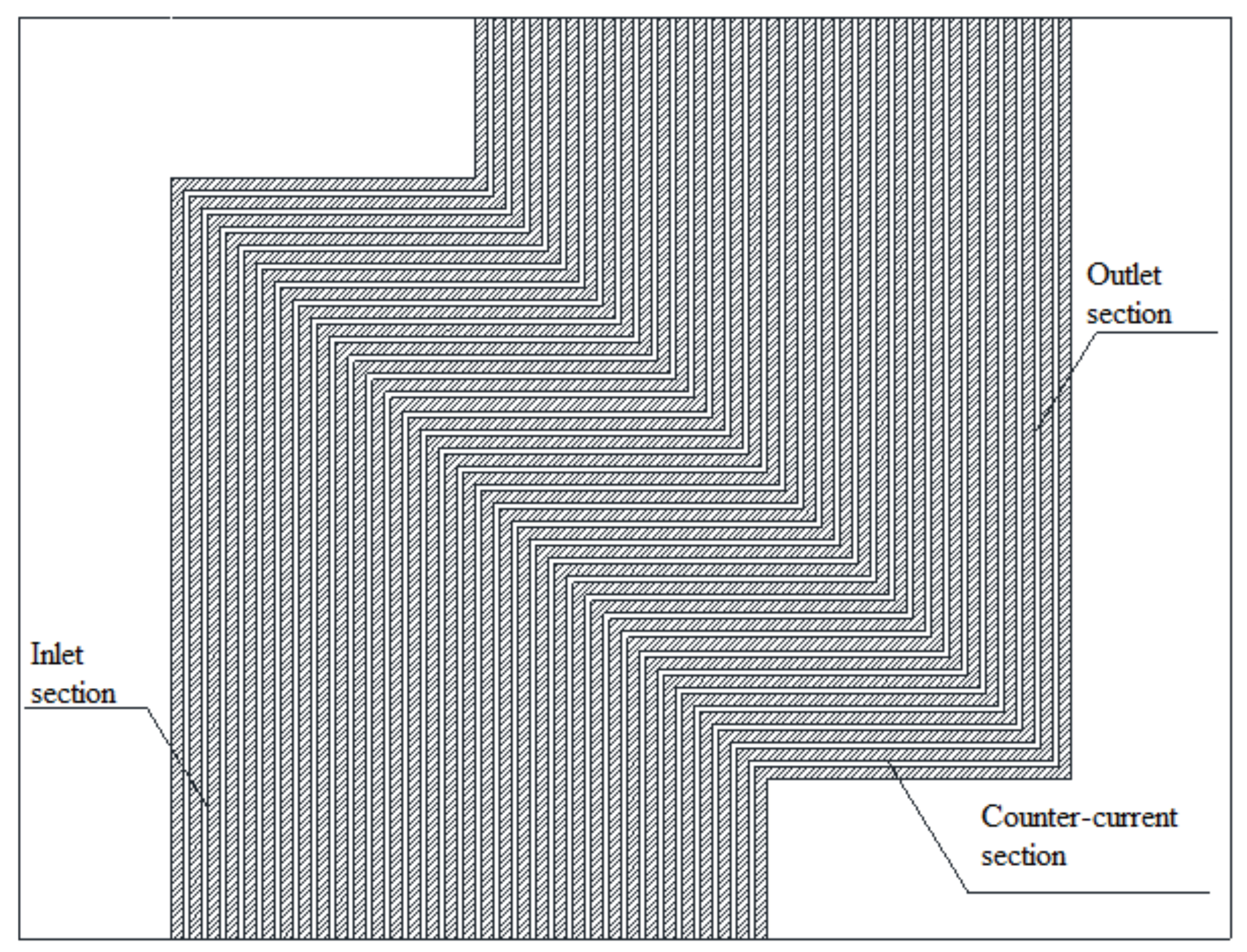
Due to the limitations of the processing technology and conditions, it is difficult to process large-sized PCHEs. Presently, the use of square plates is an effective way to improve the heat transfer power of a single heat exchanger unit. However, the inlet and outlet parts occupy a large heat transfer area in the nearly square plate using the traditional single-in and single-out flow, resulting in the area of the counter-current heat transfer part in the middle being very limited, as shown in 
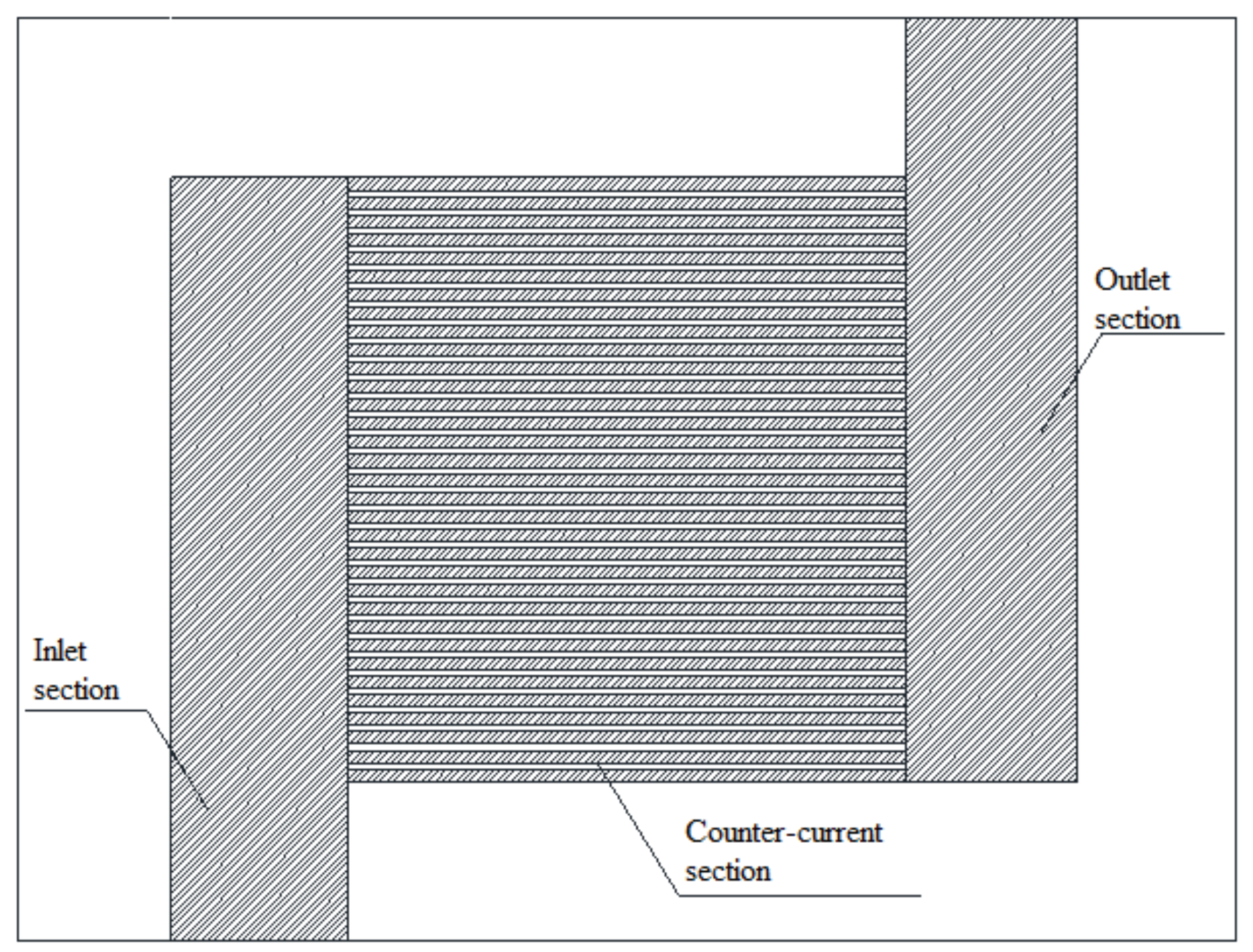
Figure 1, and greatly influencing the heat transfer efficiency of PCHE. The use of a collecting flow in the inlet and outlet will greatly reduce the space occupied by the inlet and outlet parts which, in turn, will maximize the length of the counter-current heat transfer part, as shown in Figure 2. The flow distribution was very inhomogeneous on the heat exchanger plate between the inlet and outlet, due to the different pressures of the different channels, which will lead to a significant decrease in the heat transfer efficiency of PCHE and an increase in the flow resistance [19].
Therefore, the uniformity of flow distribution is a key factor affecting the performance of PCHE [20]. In this paper, a PCHE numerical model was established. The flow distribution and resistance characteristics of a PCHE with collecting flow plates at the inlet and outlet were studied by using different flow distribution cases.
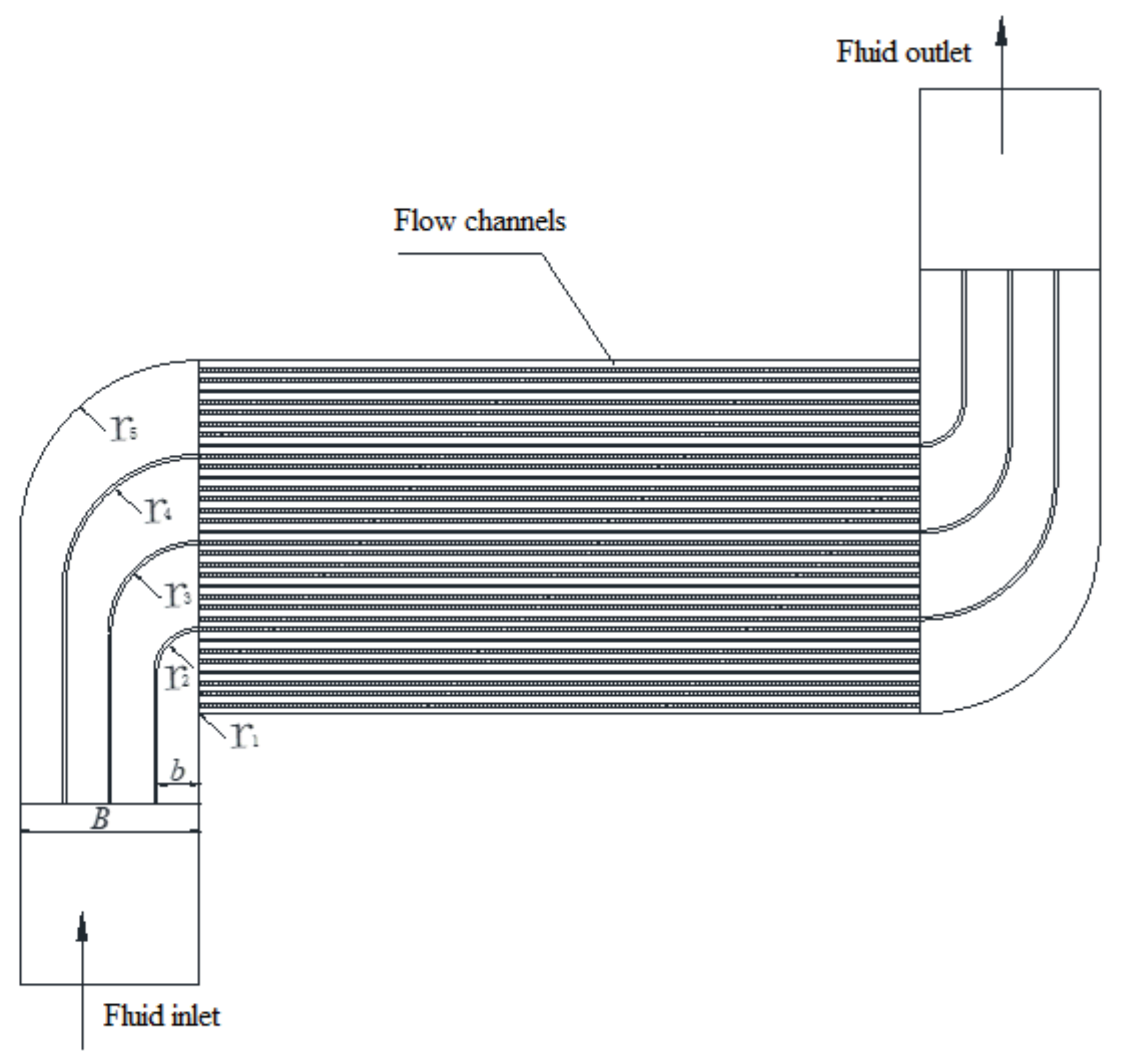
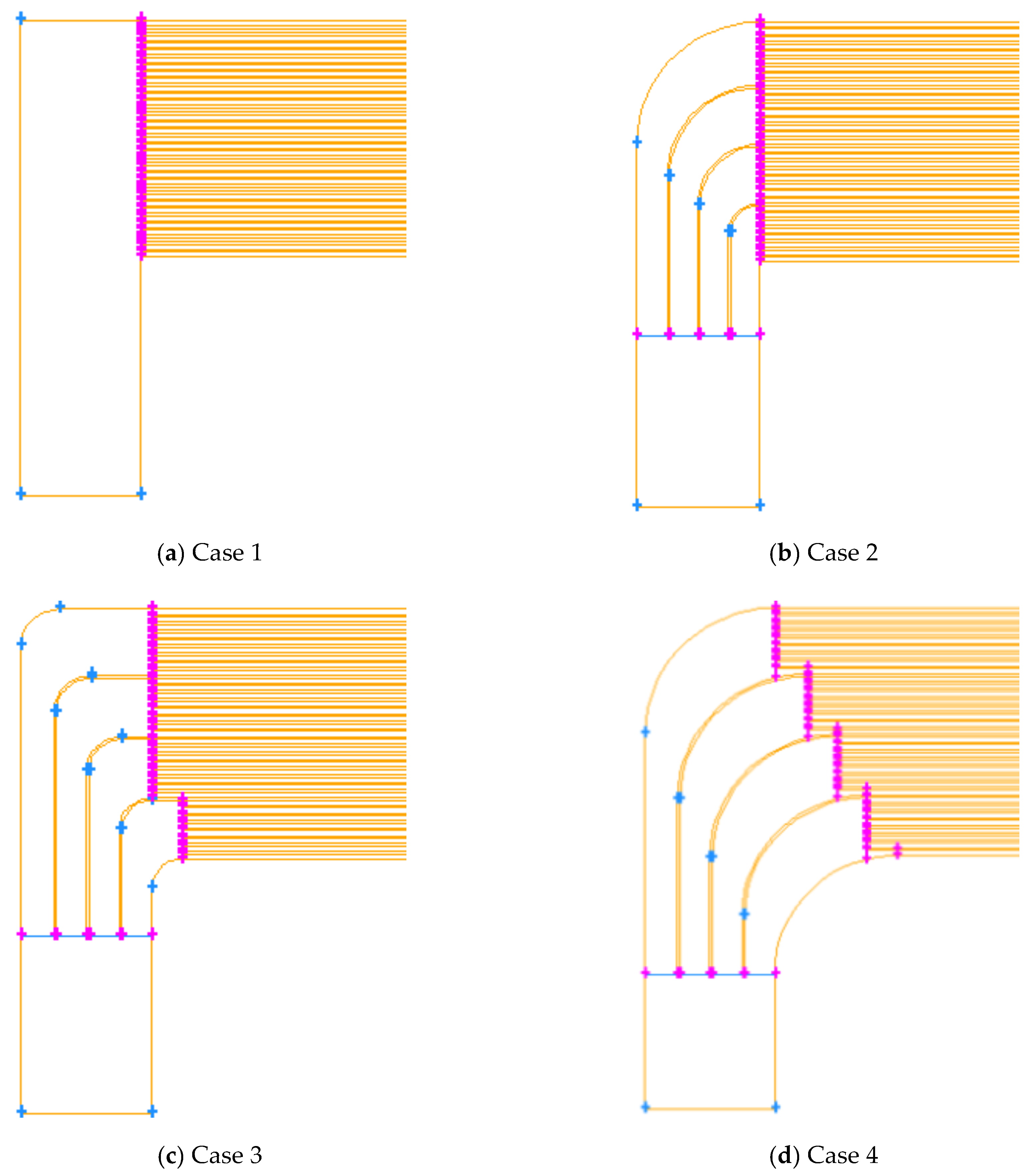
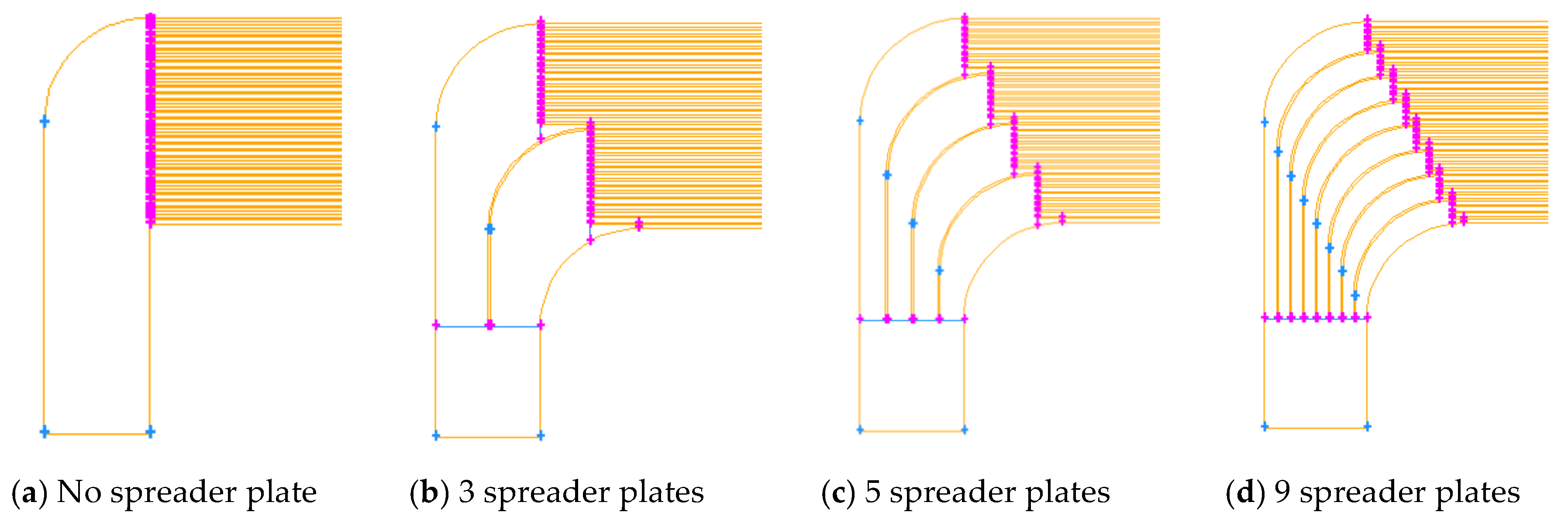
The calculation model is shown in Figure 3, combining the existing problems, and the heat exchanger plate was set with a collecting flow at the inlet and outlet. Some spreader plates were placed in the inlet and outlet parts to improve the uniformity of flow distribution within the channels. The width between the inlet and outlet is B, the width between spreader plates is b, and the radius of spreader plates are r1, r2, r3, r4, r5 respectively.

2.2. Assumptions

In order to facilitate the study of the computational model, the following assumptions must be defined:
(1)
Flow is steady and isothermal, and fluid properties are independent of time;
(2)
Fluid density is dependent on the local temperature only, or is treated as a constant;
(3)
Fluid slip at the solid-fluid interfaces is neglected;
(4)
Thermo-physical properties of fluid are independent of temperature variations;
(5)
Body forces are caused only by gravity (i.e., magnetic, electrical, and other fields do not contribute to the body forces);
(6)
Newtonian fluid, incompressible flow and turbulent flow.

2.3. Governing Equations

The governing equations describe the operation of fluid flow inside the channel. When the governing equations were used to directly model the flow, it was necessary to use small time and space steps to distinguish the detailed spatial structure and the time-varying temporal characteristics in turbulence. However, this requires a large amount of memory space and a very high CPU operating speed. Therefore, the direct numerical calculation of the governing equation is still difficult to use in engineering calculations. However, if the turbulence models in FLUENT (like the k-ε model) are introduced to simplify the N-S equation, it can be applied to engineering calculations. The general form of all the governing equations in the fluid domain for the present steady-state problem is shown as follows:
div ( ρ V ϕ ) = div [ Γ g r a d ( ϕ ) ] + S
It should be noted that the above equation can be used for describing the equations of continuity, momentum, turbulent dissipation rate and turbulence energy.
For the equation of continuity:
ϕ = 1 ,   Γ = 0 ,   S = 0
For the equations of momentum (u, v, w):
u :   ϕ = u ,   Γ = η e f f ,   S = p x + η e f f ( 2 u x 2 + 2 v x y + 2 w x z )
v :   ϕ = v ,   Γ = η e f f ,   S = p y + η e f f ( 2 u y x + 2 v y 2 + 2 w y z )
w :   ϕ = w ,   Γ = η e f f ,   S = p z + η e f f ( 2 u z x + 2 v z y + 2 w z 2 )
For the equation of turbulent dissipation rate (k):
ρ u j k x j = x j [ ( η + η t σ k ) k x j ] + η t u i x j ( u i x j + u j x i ) ρ ε
For the equation of turbulence energy (k):
ρ u k ε x k = x k [ ( η + η t σ ε ) ε x k ] + c 1 ε k η t u i x j ( u i x j + u j x i ) c 2 ρ ε 2 k
η t   can   be   written   as   η t = c μ ρ k 1 2 l = ( c μ c D ) ρ k 2 1 c D k 3 2 / l = c μ ρ k 2 / ε . In the above equations, the parameter ρ means the density of the fluid, S represents the source item; l means the characteristic length of the turbulent channel; k means the turbulence energy; ε means the turbulent dissipation rate; CD, C1, C2 means the empirical constant.

2.4. Boundary Conditions

Inlet: Velocity Inlet Boundary Condition
In the velocity inlet boundary condition, the stagnation point parameters of the inlet boundary in the flow field are not fixed. In order to satisfy the velocity condition at the inlet, the stagnation point parameter will fluctuate within a certain range.
Outlet: Outflow Outlet Boundary Condition
The boundary condition of free outflow is subject to the assumption of fully developed turbulence. Fully developed flow means that the flow field variables do not change in the flow direction, that is, the diffusion flux of all flow variables is equal to zero in the normal direction of the outlet boundary.

2.5. Numerical Details

The viscosity in the solid domain is considered infinite. The thermo-physical properties of the working fluid can be calculated based on its temperature and pressure, as shown in Table 1. In this table, some of the permanent parameters in the numerical simulation are clearly presented, including channel type, number of channels, plate size, channel size, channel spacing, the width of the inlet and the outlet, the working fluid, pressure, and inlet velocity.

3. Results and Discussion

3.1. Grid Independence Check

For the grid-independence verification, five numerical calculation steps with 1, 0.5, 0.3, 0.2 and 0.1 mm were carried out in this paper. As shown in Section 2, the numerical model had 33 channels in the counter-current section. Figure 4 shows the flow rate variations of two representative channels (1 and 33). It can be seen that, when the grid number reached 80,850 with a step size of 0.2 mm, the results changed a little (<1%) with the increase in the grid number, which means a step size of 0.2mm was small enough for this numerical model. Therefore, a step size of 0.2 mm was used in the subsequent calculations.

3.2. Analysis of Flow Maldistribution

In order to evaluate the flow distribution characteristics within the channels, 33 channels were numbered from bottom to top along the flow direction from the inlet. In order to compare the flow distribution uniformity of 33 channels under different flow rates, two parameters, i.e., flow distribution nonuniformity in each PCHE channel Ei and the average flow distribution nonuniformity in all PCHE channels S are defined as follows:
E i = m i m a i = 1 n m i
S = 1 n 1 i = 1 n ( m i m a 1 ) 2
where, Ei is used to characterize the flow distribution nonuniformity between different channels, S is used to characterize the total flow distribution nonuniformity of the heat exchanger, mi is the flow rate in the ith channel, ma is the average flow rate for one single channel and n is the number of channels.

3.3. Flow Distribution Case

In order to improve the uniformity of traffic distribution in the channel, this paper studied the flow distribution characteristics in different cases, as shown in Figure 5. The parameters of the different cases are shown in Table 2. Case 1 used no spreader plate. Case 2 used the spreader plate with an increase in the inner and outer radius. Case 3 used the spreader plate with an equal inner and outer radius. Case 4 used the spreader plate with an equal inner and outer radius, also with a large bending radius.
Figure 6 shows the streamlines for the different cases with an inlet velocity of 40 m/s. It was observed that, when the spreader plate is not used (Case 1), the angle of the fluid was large when fluid flowed into the channel, which caused a clear flow separation and a strong eddy current at the inlet of the channel. The flow separation area occupied the largest section. When the spreader plates in Cases 2 and 3 were used, the flow separation at the inlet of the channel gradually improved, and the flow separation and vortex area were greatly reduced. When the spreader plate in Cases 4 was used, the radius of the spreader plate was greatly increased, but the angle of the fluid was greatly reduced, which meant there was basically no flow separation in the channel.
Figure 7 shows the flow distribution in the channel for the different cases with an inlet velocity of 40 m/s. Compared with Figure 6, it can be seen the flow distribution in different channel was very inhomogeneous due to the violent flow separation at the inlet of the channel in Case 1. The flow at the inlet of the channel in Case 2 and 3 improved gradually, but the flow separation and vortex area greatly decreased, and the imbalance of flow distribution of the channel greatly improved. There was barely any flow separation phenomenon at the inlet of the channel in Case 4, and the imbalance of the flow distribution was also decreased with ±0.8%.
Figure 8 shows the nonuniformity variation in the total flow distribution with the different inlet velocity. It was observed that the nonuniformity of flow distribution decreased from Case 1 to Case 4, which indicates that the uniform flow distribution corresponded with the smaller flow rate and dispersion of the average flow in the channel. With an increase in the inlet velocity, the nonuniformity of the flow distribution of each case increased. In the inlet velocity range, as shown in Figure 8, the nonuniformity of the flow distribution was within 9%, indicating that the uniformity of the flow distribution was good.
Figure 9 shows the variation in pressure drop between the inlet and outlet with different velocities. Compared with Figure 6, Figure 8 and Figure 9, the pressure drop was great in Case 1 due to a very serious flow separation, which caused an inhomogeneous flow distribution. When the spreader plate was added in Cases 2 and 3, the flow separation improved and the flow distribution was more uniform, so the flow resistance was greatly reduced. There was barely any flow separation phenomenon in Case 4. The flow distribution uniformity in this case was the best. Therefore, the flow resistance was also the minimum.

3.4. Numbers of Spreader Plate

In order to improve the uniformity of the flow distribution in the channel further, the flow distribution characteristics of different spreader plates were studied based on Case 4, as shown in Figure 10. The radius of the spreader plate was set as r1 = r2 = r3 = r4 = r5 = 4b.
Figure 11 shows the flow distribution in the channel with different numbers of spreader plates. It was shown that with an increase in the spreader plates and partitions, the imbalance of the flow distribution in the channel was greatly improved. When the number of spreader plates reached nine, the imbalance of the flow distribution was reduced to ±0.2%.
Figure 12 shows the nonuniformity variation in the total flow distribution with the inlet velocity under different spreader plates. With an increase in the number of spreader plates, the nonuniformity of the flow distribution decreased, indicating that the uniform flow distribution corresponded with the smaller flow rate and dispersion of the average flow in the channel. With an increase in the inlet flow rate, the nonuniformity of the flow distribution of each model increased. The nonuniformity of the flow distribution with no spreader plates and three spreader plates varied greatly with the velocity, but with five and nine spreader plates it only varied slightly. When the number of spreader plates reached nine, the flow distribution in the channel was less than 5%, indicating that the flow distribution was very uniform.
Figure 13 shows the variation in pressure drop between the inlet and outlet with velocities under different spreader plates. Compared with Figure 9 and Figure 13, the pressure drop was large when there were no spreader plates. When the spreader plates were added, the flow resistance was largely decreased. It was also observed that the pressure loss of nine spreader plates was larger than that of three and five spreader plates. It can be explained that, when the number of spreader plates increased, the flow cross-sectional area at the inlet and outlet increased, the flow velocity increased, and the pressure loss increased. This indicated that the number of spreader plates could not increase without limitation, which should comply with the integrated uniformity of the flow distribution, flow resistance and heat transfer efficiency.

3.5. Analysis of the Symmetry

3.5.1. Structure Central Symmetry

The whole structure of PCHE shows central symmetry. The flow distribution and resistance characteristics of a PCHE plate were studied with numerical models under different flow distribution cases. Although only the inlet part of the heat exchanger was considered and modeled in this paper, the conclusions of this paper are also applicable to the outlet part of the heat exchanger. The results show that the sudden change in the angle of the fluid at the inlet of the channel can be greatly reduced by using the spreader plate with equal inner and outer radius.

3.5.2. Channel Flow Field Symmetry

The streamlines of the flow field in the PCHE channel presents symmetry. As Figure 6 shows, there was barely any flow separation phenomenon at the inlet of the channel in Case 4 (the spreader plate with an equal inner and outer radius, also with a large bending radius), and the imbalance of the flow distribution was also decreased by ±0.8%. For the flow field at the outlet of the heat exchanger, the streamlines of the flow field exhibited the same characteristics as the inlet.

3.5.3. Adjacent Channel Structure Symmetry

The geometry of each channel of the PCHE presents structural symmetry. Therefore, the velocity field and temperature field of each channel also exhibit certain symmetric characteristics. Improving the symmetry of the adjacent channels can diminish the flow rates in adjacent channels. One goal of this study was to improve the symmetry of the structures of adjacent channels and thus ensure the symmetry of the fluid flow in adjacent channels, in order to diminish the flow rates in adjacent channels and, especially, to prevent maldistribution in the channels near the side walls of the device.

3.6. Discussion

This paper aims to present the flow distribution and resistance characteristics of PCHE plates, which were studied with numerical models under different flow distribution cases; the numerical simulation of fluid flow distribution can provide guidance for subsequent research and the design and development of multi-channel heat exchangers.
The multi-channel PCHE plate showed an obvious maldistribution effect in the practical application, which produced a great limitation in the performance promotion of the PCHE plate. This aspect was rarely investigated in the available literature. This paper analyzes the symmetry of the heat exchanger in three aspects: structure central symmetry, channel flow field symmetry and adjacent channel structure symmetry.
The results show that the sudden change in the angle of the fluid at the inlet of the channel can be greatly reduced by using the spreader plate with an equal inner and outer radius. The flow separation of the fluid at the inlet of the channel can also be weakened and the imbalance of flow distribution in the channel can be reduced. The numerical simulation of the fluid flow distribution can provide guidance for the subsequent research and the design and development of multi-channel heat exchangers.

4. Conclusions

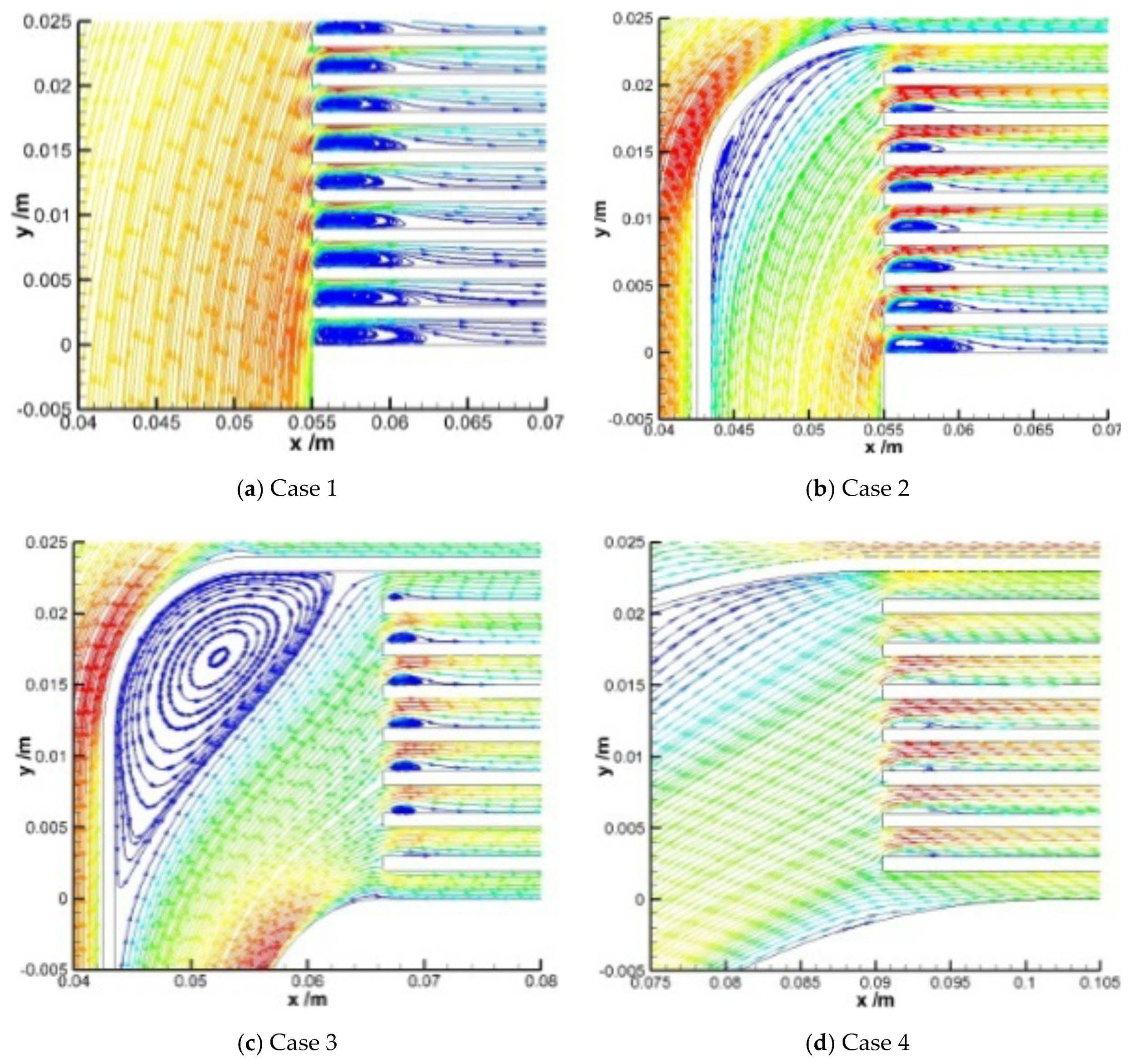
In this study, different flow distribution cases were designed and theoretically studied in order to improve the uniformity of the fluid flow distribution, and the resistance characteristics at the inlet and outlet of the PCHE channel were numerically modeled and analyzed in detail. Our conclusions can be drawn as follows:
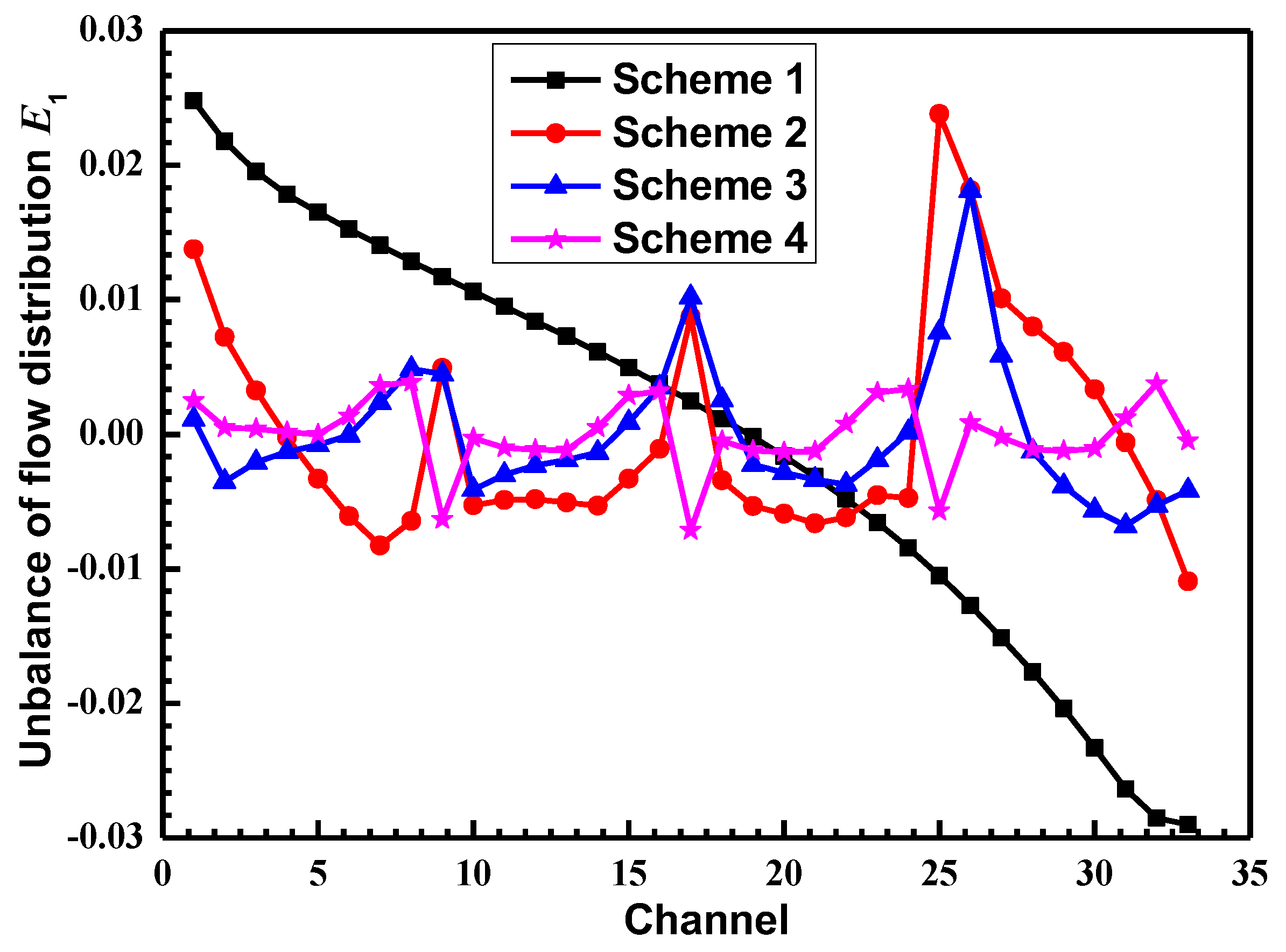
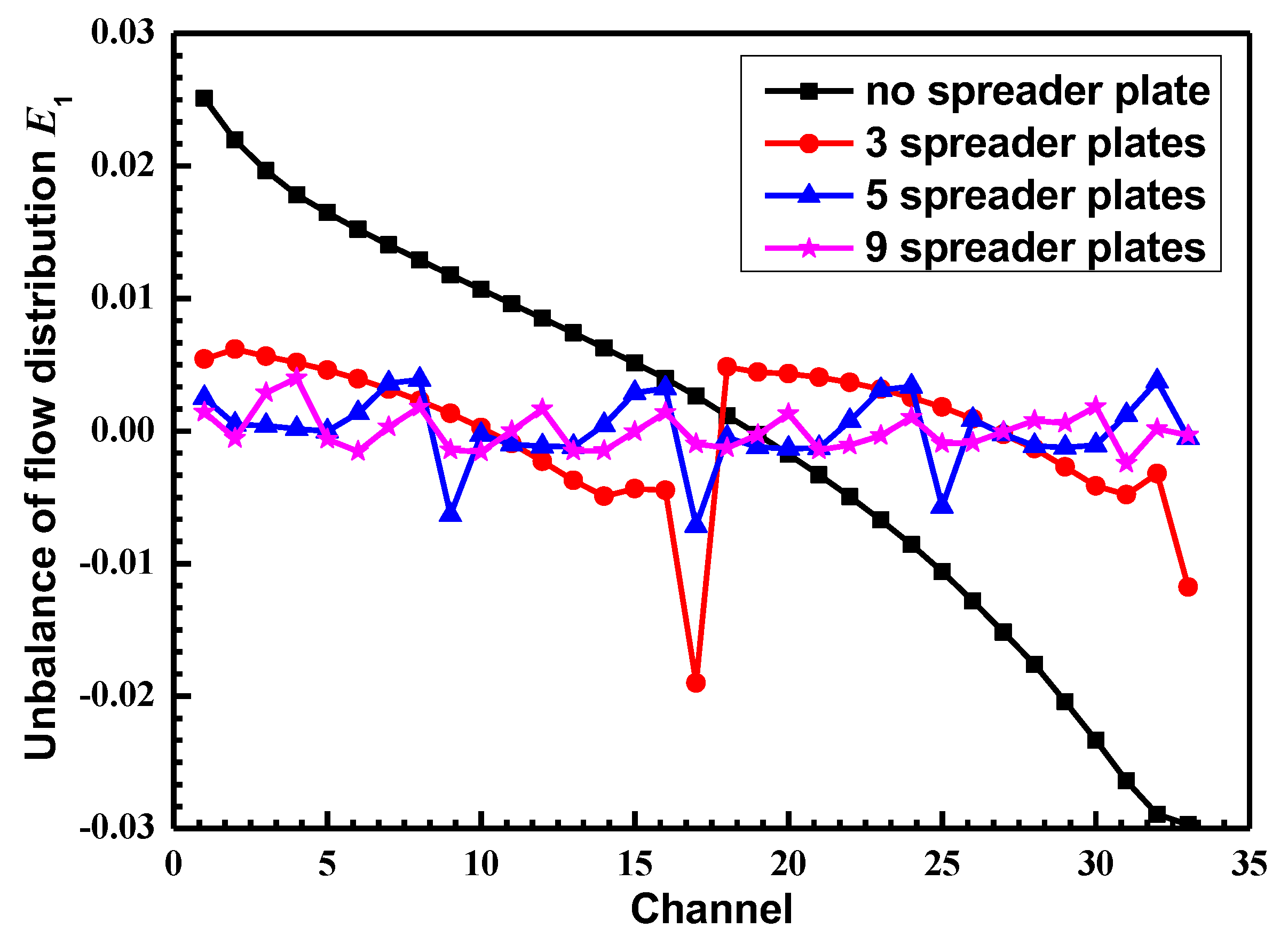
(1) With the use of the spreader plate with an equal inner and outer radius, the sudden change in the angle of the fluid at the inlet of the channel can be greatly reduced. The flow separation of the fluid at the inlet of the channel can also be weakened and the imbalance of flow distribution in the channel can be reduced. So, the flow uniformity can be improved and the pressure loss between the inlet and outlet of the PCHE can be reduced;
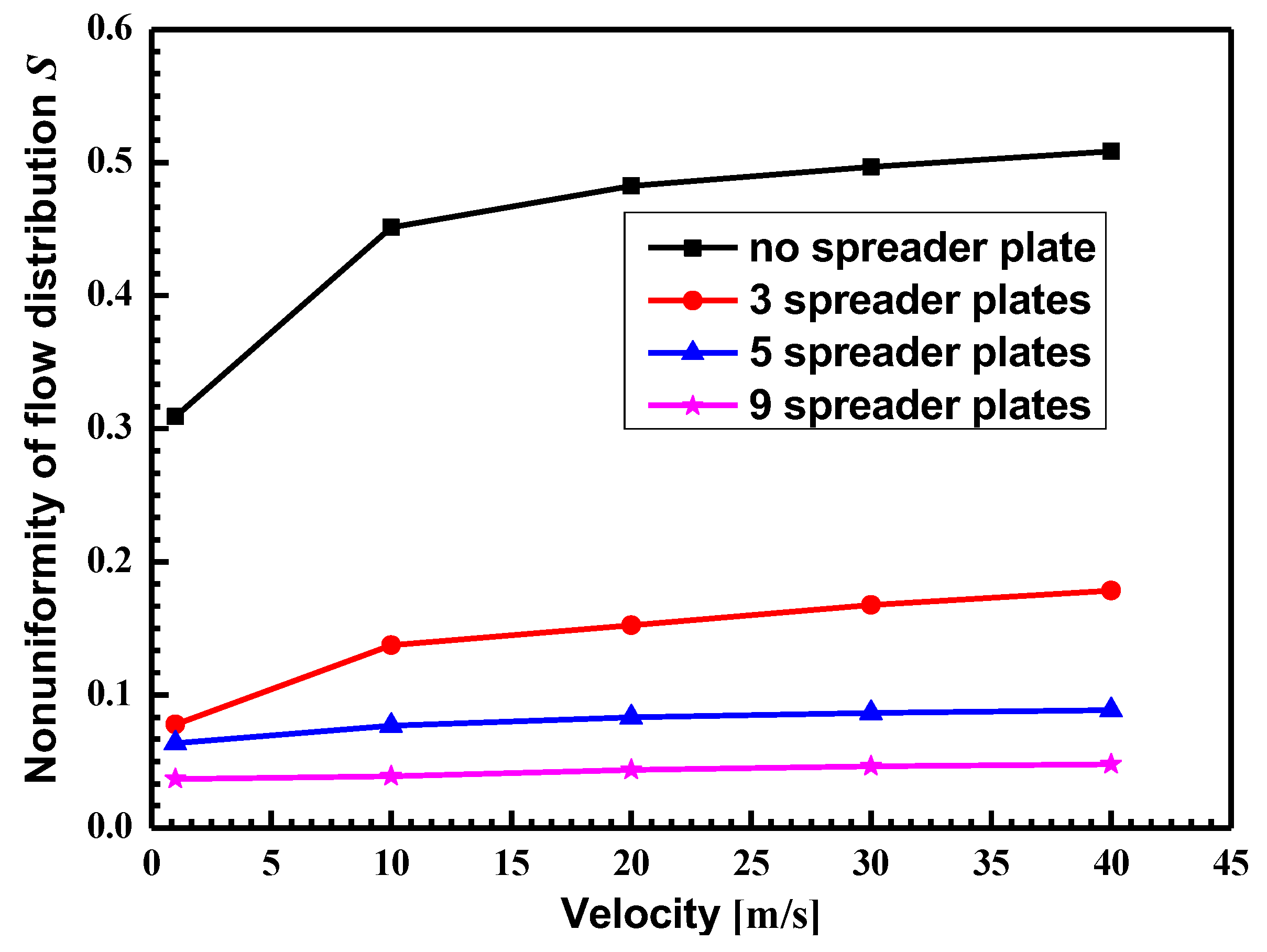
(2) With the use of nine spreader plates, the imbalance of flow distribution in the channel is basically reduced to ±0.2%, and the total flow distribution is within 5%, which indicates a good flow distribution uniformity;
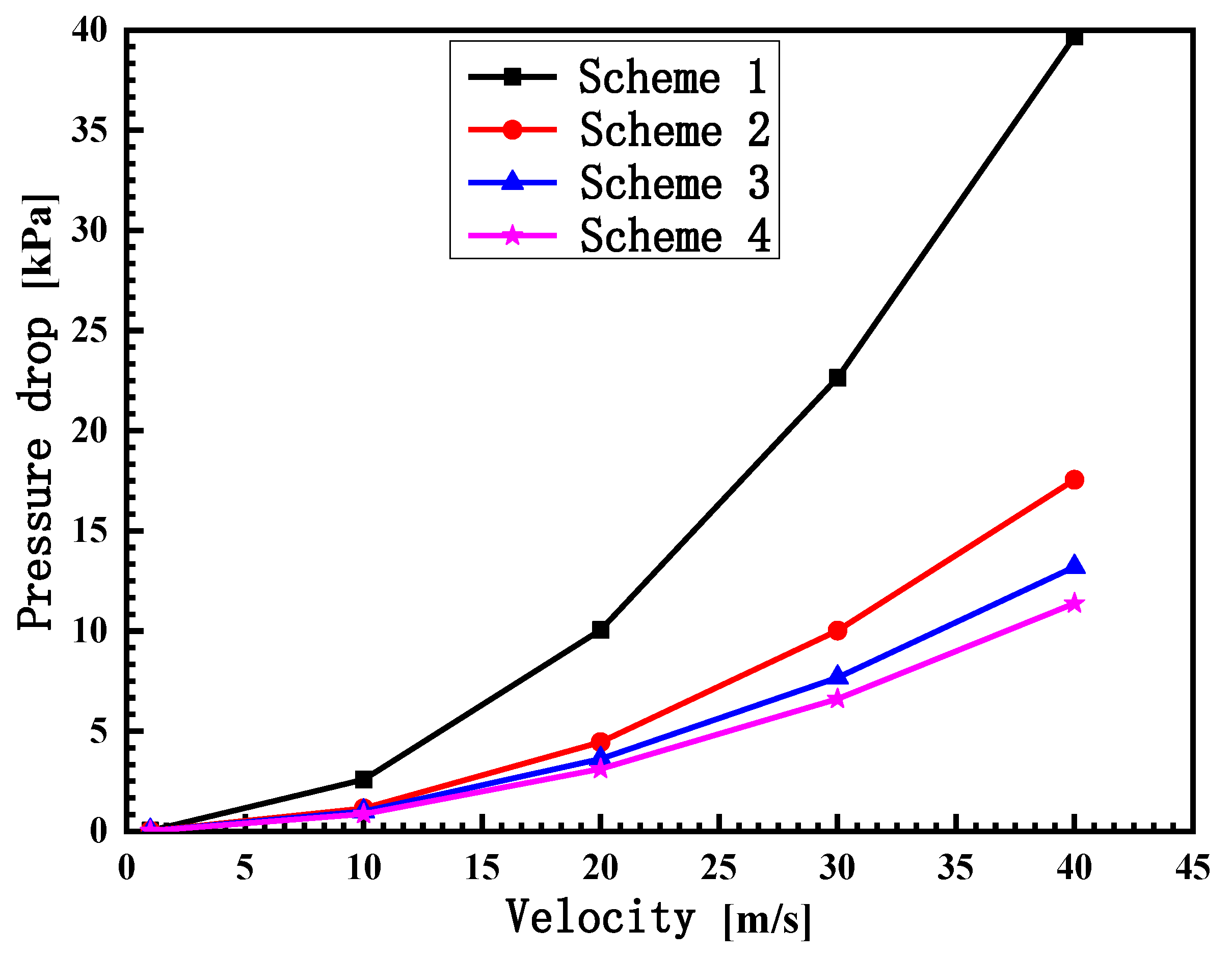
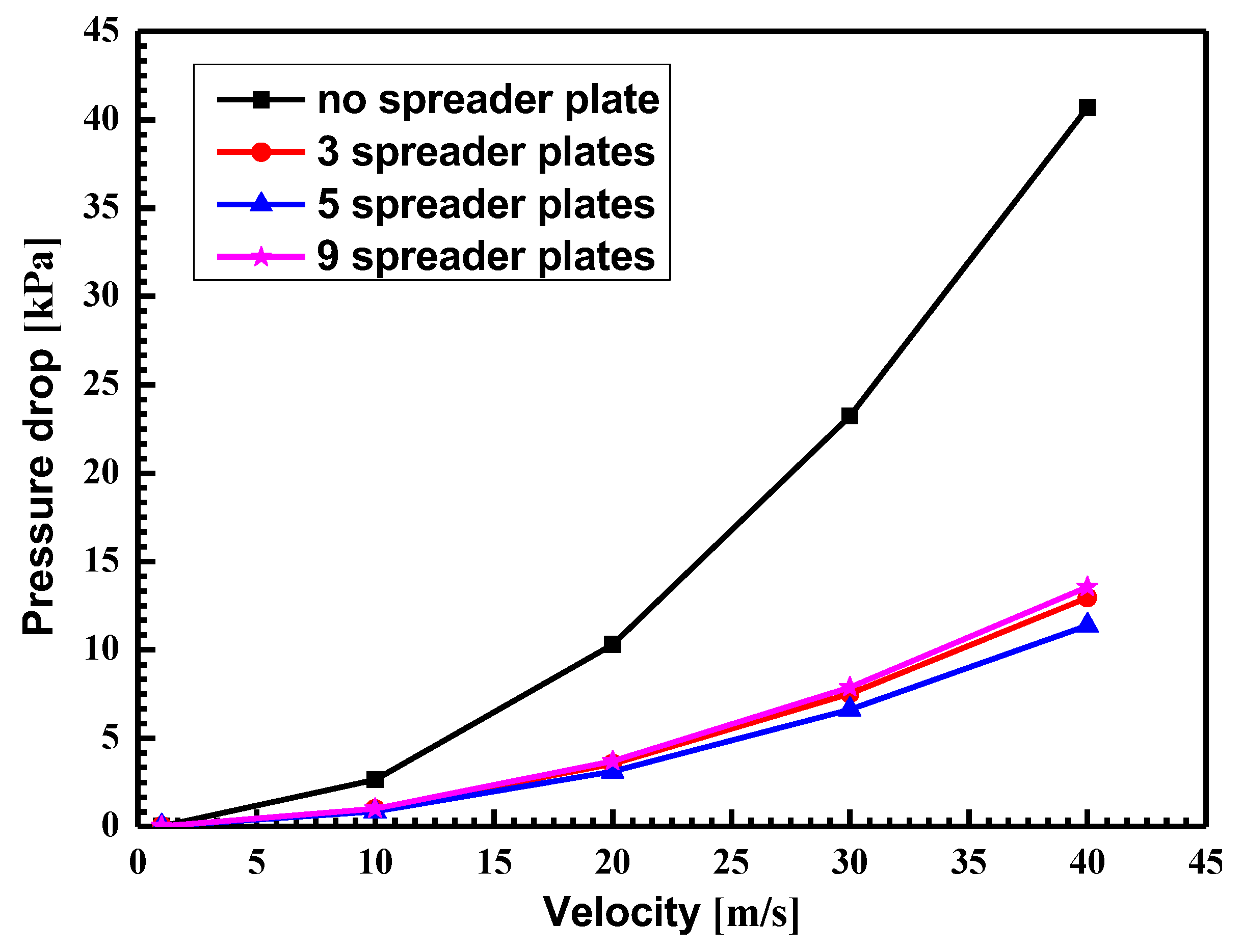
(3) The uniformity of the flow distribution increases with the increase in spreader plates. However, with the increase in the number of spreader plates, the flow cross-sectional area at the inlet and outlet increases, the flow velocity increases, and the pressure loss increases. Therefore, the number of spreader plates cannot increase without limitation, which should comply with the integrated uniformity of the flow distribution, flow resistance and heat transfer efficiency.

Author Contributions

H.K. and H.X. led the writing of the paper. H.K., Y.L., Z.K., Q.X., Z.W., K.C. and H.X. developed the numerical model. H.K., Y.L., Z.K., Q.X., Z.W., K.C. and H.X. performed the data analysis. The first version was drafted by H.K. and H.X. All authors have read and agreed to the published version of the manuscript.

Funding

This research was funded by National Natural Science Foundation of China (Nos. 51876146, 51876118), Open Fund of Science and Technology on Thermal Energy and Power Laboratory (No. TPL2018B03), and Shanghai International Science and Technology Cooperation Fund (No. 18160743800).

Acknowledgments

Chenqian Wu in Shanghai Jiao Tong University is acknowledged for some helpful discussion and useful information in improving the quality of this paper.

Conflicts of Interest

There is no conflict of interest.

References

  1. Shah, R.K.; Sekulic, D.P. Fundamentals of Heat Exchanger Design; John Wiley & Sons: Hoboken, NJ, USA, 2003. [Google Scholar]
  2. Ezgi, C.; Özbalta, N.; Girgin, I. Thermohydraulic and thermoeconomic performance of a marine heat exchanger on a naval surface ship. Appl. Therm. Eng. 2014, 64, 413–421. [Google Scholar] [CrossRef]
  3. Kakaç, S.; Liu, H.; Pramuanjaroenkij, A. Heat Exchangers: Selection, Rating, and Thermal Design; CRC Press: New York, NY, USA, 2002. [Google Scholar]
  4. Farajollahi, B.; Etemad, S.G.; Hojjat, M. Heat transfer of nanofluids in a shell and tube heat exchanger. Int. J. Heat Mass Transf. 2010, 53, 12–17. [Google Scholar] [CrossRef]
  5. Tsuzuki, N.; Kato, Y.; Ishiduka, T. High performance printed circuit heat exchanger. Appl. Therm. Eng. 2007, 27, 1702–1707. [Google Scholar] [CrossRef]
  6. Sabharwall, P.; Kim, E.S.; McKellar, M.; Anderson, N. Process Heat Exchanger Options for the Advanced High Temperature Reactor; Idaho National Laboratory (INL): Idaho Falls, 2011.
  7. Bartel, N.; Chen, M.; Utgikar, V.; Sun, X.; Kim, I.-H.; Christensen, R.; Sabharwall, P. Comparative analysis of compact heat exchangers for application as the intermediate heat exchanger for advanced nuclear reactors. Ann. Nucl. Energy. 2015, 81, 143–149. [Google Scholar] [CrossRef] [Green Version]
  8. Shin, C.W.; No, H.C. Experimental study for pressure drop and flow instability of two-phase flow in the PCHE-type steam generator for SMRs. Nucl. Eng. Des. 2017, 318, 109–118. [Google Scholar] [CrossRef]
  9. Ma, T.; Li, L.; Xu, X.-Y.; Chen, Y.-T.; Wang, Q.-W. Study on local thermal–hydraulic performance and optimization of zigzag-type printed circuit heat exchanger at high temperature. Energy Convers. Manag. 2015, 104, 55–66. [Google Scholar] [CrossRef]
  10. Yang, H.; Wen, J.; Gu, X.; Liu, Y.; Wang, S.; Cai, W.; Li, Y. A mathematical model for flow maldistribution study in a parallel plate-fin heat exchanger. Appl. Therm. Eng. 2017, 121, 462–472. [Google Scholar] [CrossRef]
  11. Jiao, A.; Zhang, R.; Jeong, S. Experimental investigation of header configuration on flow maldistribution in plate-fin heat exchanger. Appl. Therm. Eng. 2003, 23, 1235–1246. [Google Scholar] [CrossRef]
  12. Bobbili, P.R.; Sunden, B.; Das, S.K. An experimental investigation of the port flow maldistribution in small and large plate package heat exchangers. Appl. Therm. Eng. 2006, 26, 1919–1926. [Google Scholar] [CrossRef]
  13. Zhang, Z.; Mehendale, S.; Tian, J.; Li, Y. Experimental investigation of distributor configuration on flow maldistribution in plate-fin heat exchangers. Appl. Therm. Eng. 2015, 85, 111–123. [Google Scholar] [CrossRef]
  14. Zhang, Z.; Li, Y. CFD simulation on inlet configuration of plate-fin heat exchangers. Cryogenics 2003, 43, 673–678. [Google Scholar] [CrossRef]
  15. Wen, J.; Li, Y.; Zhou, A.; Zhang, K. An experimental and numerical investigation of flow patterns in the entrance of plate-fin heat exchanger. Int. J. Heat Mass Transf. 2006, 49, 1667–1678. [Google Scholar] [CrossRef]
  16. Sheik Ismail, L.; Ranganayakulu, C.; Shah, R.K. Numerical study of flow patterns of compact plate-fin heat exchangers and generation of design data for offset and wavy fins. Int. J. Heat Mass Transf. 2009, 52, 3972–3983. [Google Scholar] [CrossRef]
  17. Wei, Z.; Yang, W.; Xiao, R. Pressure Fluctuation and Flow Characteristics in a Two-Stage Double-Suction Centrifugal Pump. Symmetry 2019, 11, 65. [Google Scholar] [CrossRef] [Green Version]
  18. Afridi, M.I.; Tlili, I.; Goodarzi, M.; Osman, M.; Khan, N.A. Irreversibility analysis of hybrid nanofluid flow over a thin needle with effects of energy dissipation. Symmetry 2019, 11, 663. [Google Scholar] [CrossRef] [Green Version]
  19. Shi, H.-N.; Ma, T.; Chu, W.-X.; Wang, Q.-W. Optimization of inlet part of a microchannel ceramic heat exchanger using surrogate model coupled with genetic algorithm. Energy Convers. Manag. 2017, 149, 988–996. [Google Scholar] [CrossRef]
  20. Koo, G.-W.; Lee, S.-M.; Kim, K.-Y. Shape optimization of inlet part of a printed circuit heat exchanger using surrogate modeling. Appl. Therm. Eng. 2014, 72, 90–96. [Google Scholar] [CrossRef]
Figure 1. Heat exchanger plate with single inlet and outlet.
Symmetry 12 00314 g001
Figure 2. Heat exchanger plate with collecting flow at the inlet and outlet.
Symmetry 12 00314 g002
Figure 3. Calculation model for the multi-channel heat exchanger.
Symmetry 12 00314 g003
Figure 4. Validation of grid independence.
Symmetry 12 00314 g004
Figure 5. Configurations of different cases.
Symmetry 12 00314 g005
Figure 6. Streamlines of different cases.
Symmetry 12 00314 g006
Figure 7. Imbalance of flow distribution for different cases.
Symmetry 12 00314 g007
Figure 8. Nonuniformity of flow distribution for different cases.
Symmetry 12 00314 g008
Figure 9. Variation in the pressure drop with different velocities.
Symmetry 12 00314 g009
Figure 10. Different numbers of spreader plates.
Symmetry 12 00314 g010
Figure 11. Imbalance of flow distribution for different numbers of spreader plates.
Symmetry 12 00314 g011
Figure 12. Nonuniformity of flow distribution for different numbers of spreader plates.
Symmetry 12 00314 g012
Figure 13. Variation in the pressure drop with different numbers of spreader plates.
Symmetry 12 00314 g013
Table 1. PCHE parameters.
ParameterValue
Channel typeSquare straight channel
Number of channels33
Plate size300 mm × 200 mm
Channel size2 mm × 1 mm
Channel spacing1 mm
Inlet and outlet width50 mm
Working fluidwater
Pressure0.3 MPa
Inlet velocity0–40 m/s
Table 2. Parameters of PCHE plates for flow distribution.
CasesParameters
1No spreader plate
2r1 = 0, r2 = b, r3 = 2b, r4 = 3b, r5 = 4b
3r1 = r2 = r3 = r4 =r5 = b
4r1 = r2 = r3 = r4 = r5 = 4b
Inlet velocity0–40 m/s

