1. Introduction
The phenomena of shock wave asymmetry, in which the λ-foot on one wall of the nozzle is of a different size than on the other wall is very common in the field of supersonic internal flows. By now it is well established that the height of λ-foot is influenced by the Reynolds number [
1,
2], Mach number [
3] and the characteristic length scale of boundary layer thickness [
4]. In the internal flows, when the shock wave—boundary layer interaction (SWBLI) is constrained by the nozzle there is an additional characteristic feature which is the channel height. The generation of λ-foot asymmetry in a non-symmetric nozzle [
5] is explained by the fact that flow parameters are different at each nozzle wall [
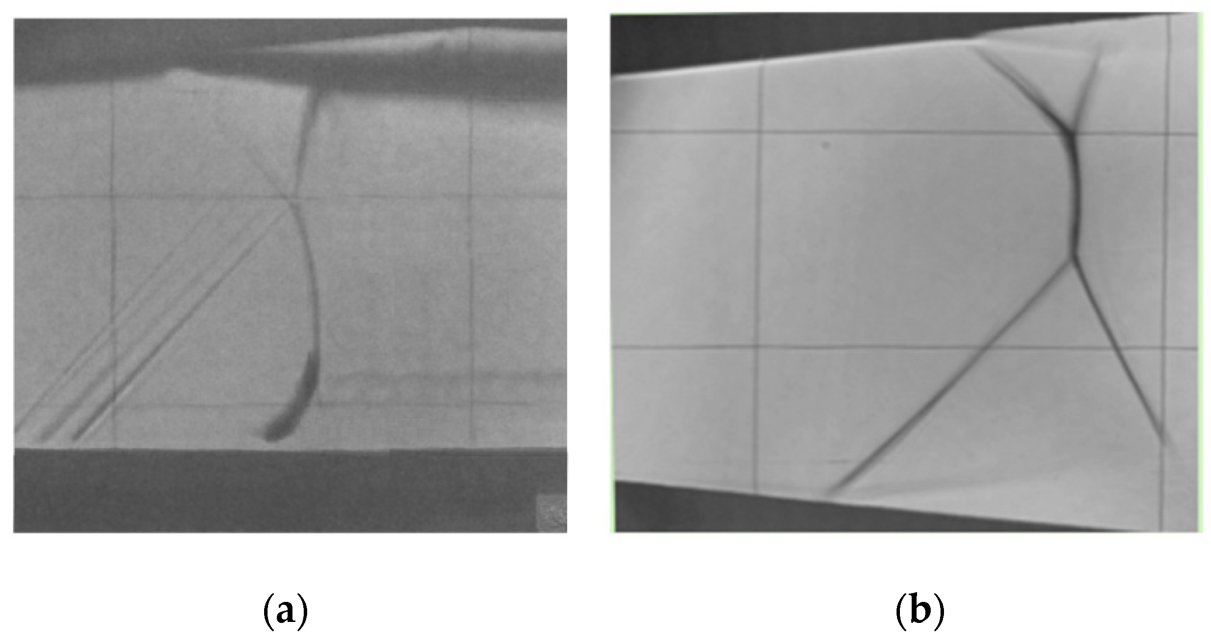
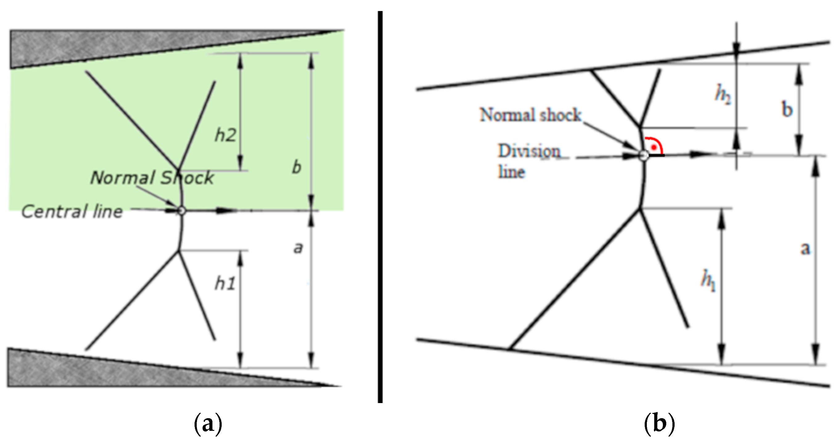
6]. An example is presented in
Figure 1a schlieren visualization of flow in the very widely exploited experimental case of a ‘half-nozzle’ with flat bottom wall [
7]. In this case, as the nozzle is not symmetric, the above parameters are different on the top and bottom wall giving fairly clear reasons for the asymmetry to arise.
The phenomenon of λ-foot has been known and widely investigated for over forty years now [
8,
9,
10,
11,
12], and still draws a lot of attention [
13,
14]. The knowledge of some aspects of this phenomena is increasing. The authors of [
15] report the conditions promoting asymmetry and factors driving to this. The authors of [
16,
17,
18] report that the location of the largest lambda shock of the asymmetric pattern can be forced either on the top, or on the bottom wall, by means of roughness placed on the wall in the throat region.
Also in the field of CFD a lot of work is being done, ranging from the basic general approaches [
19] to the more detailed ones. The authors of [
20] propose a model based on the properties of fluid entrainment in the mixing layer and momentum conservation, concluding that the entrainment of shear layer on the separation is one of the reasons for the asymmetry in the confined SBLI. One of the major problems of CFD still awaiting solution is that in the CFD results the side (top or bottom nozzle wall) that the larger foot occupies remains unchanged for repeated ‘flows’. The experiments [
20] and author of this paper clearly show, that in experiment the asymmetry can ‘flip’ between the flows [
20]. Yet, the phenomenon of flow asymmetry in symmetric nozzle is still waiting for a full explanation and development of appropriate numerical tools [
21].
Figure 1b illustrates a schlieren visualization of flow in a fully, symmetric nozzle with different λ-foot size at each nozzle wall.
In spite of the nozzle symmetry the asymmetry of flow structure is clear for this case in
Figure 1b. The understanding of reasons behind this counterintuitive asymmetry of the λ-foot system in a symmetric nozzle is still very low [
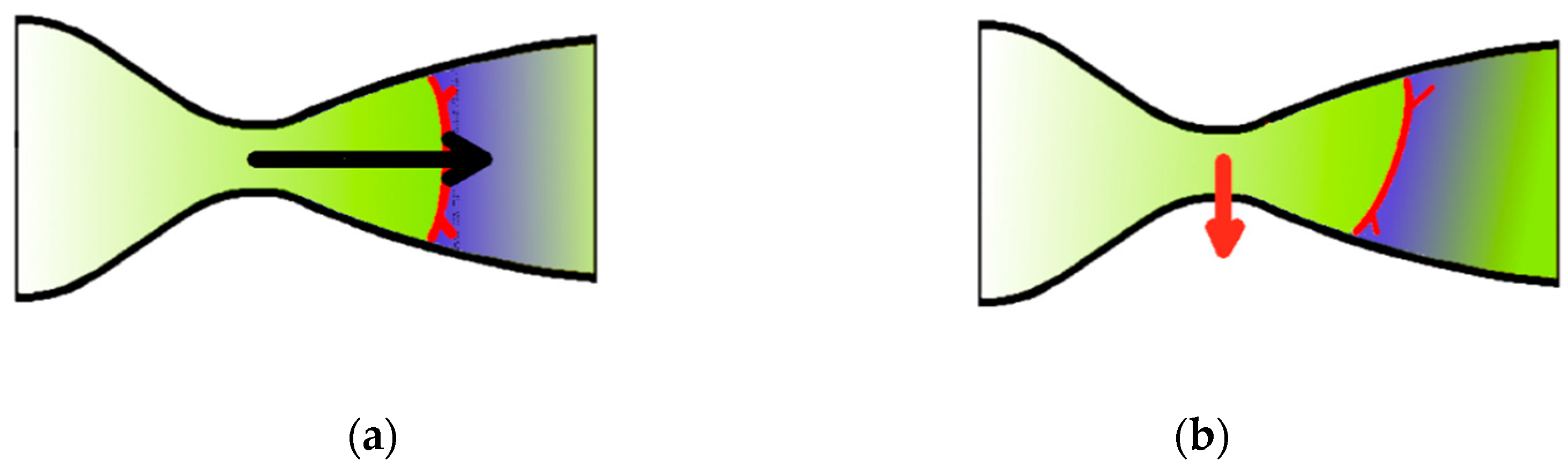
22]. The asymmetry causes different pressure distribution on the top and bottom wall of a nozzle. This generates a transversal force exerted on the nozzle by the flow. The existence of this component can have very severe consequences especially for a space vehicle. For a typical convergent-divergent propelling nozzle, the conditions promoting asymmetry are present especially during the take-off stage. At this stage, the nozzle is facing the highest possible pressure at the outlet, and the shock is located deep inside the nozzle [
23], as depicted in
Figure 2.
The solid black arrow represents flow in the symmetric case. The red arrow represents the presence of side force in the asymmetric case. In
Figure 2a the shock system is symmetric thusly the generated thrust is axial (with zero transverse component). On the contrary,
Figure 2b illustrates the situation of asymmetric shock system. The lack of symmetry results in different pressure distributions on the top and bottom wall of the nozzle, creating a non-zero traverse component of the net force (marked with red arrow). This force can cause severe consequences during the take-off stage of a space vehicle.
In respect to various nozzle shapes and flow patterns of the shock wave, a general classification of restricted shock separation (RSS) and free shock separation (FSS) is broadly recognized in nozzle flows. It is based on the behaviour of shock-induced boundary layer separation. If the separation is in a form of a bubble, restricted by reattachment line still inside the nozzle then it is a RSS. If there is no reattachment inside the nozzle and the separation extends outside the nozzle, one considers the flow as FSS. It is known that side loads resulting from FSS are significantly greater than those generated by RSS [
24]. The extreme values of the side force are also reported to accompany the transition from FSS to RSS [
23], but this is not the case of our considerations now. We are looking into the asymmetry of λ-shock system in a quasi-steady state RSS type flow. In our experiments the flow was always an RSS type. The attempt to explain the counterintuitive asymmetry of the λ-shock system is the main topic of the paper hereafter.
2. Experimental Setup
The measurements were carried out at the IMP PAN supersonic wind tunnel facility. The wind tunnel is an intermittent, vacuum type wind tunnel, described in more detailed manner in [
25]. The test section with a nozzle is schematically depicted in
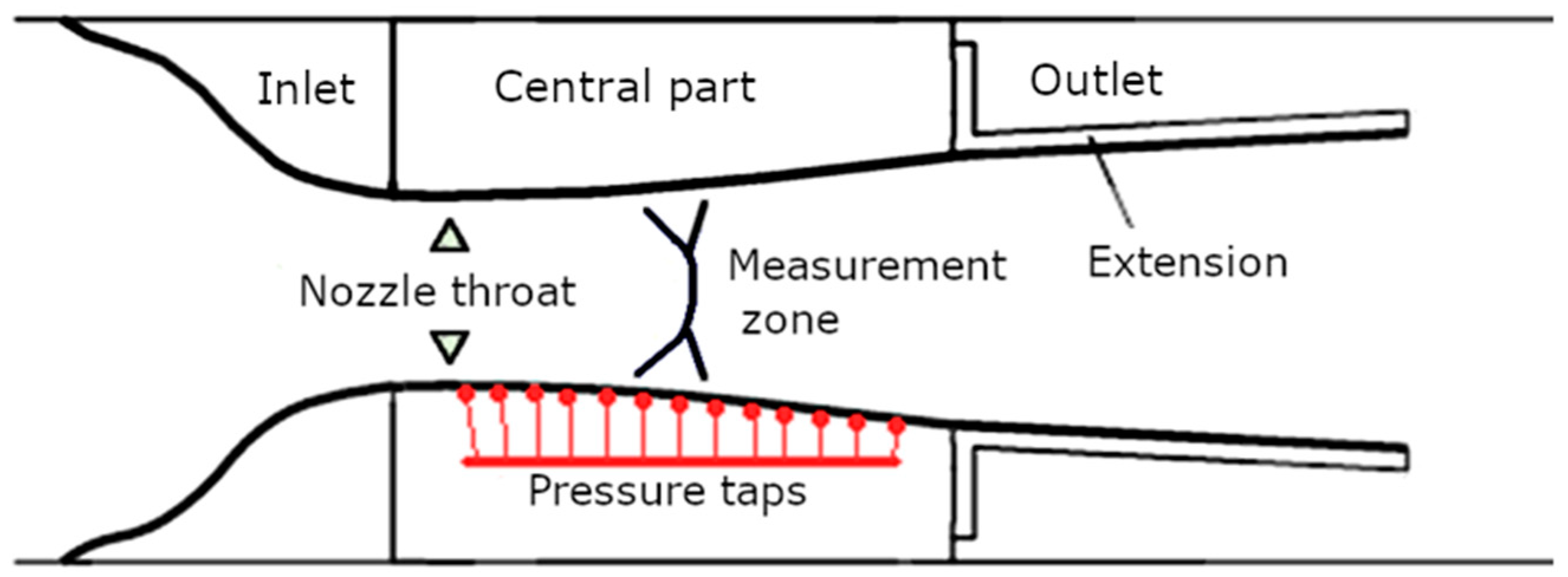
Figure 3.
The nozzle is composed of carefully machined and mounted identical top and bottom walls. Each of them consists of three elements indicated in the sketch in
Figure 3: the inlet part, the central part and the outlet part. The shape of the nozzle central part is a spline followed by a straight line. The nozzle part with rectilinear walls is the test region where the investigated shock waves were located. The outlet part is also rectilinear and in the present measurements its inclination was the same as in the central part. Therefore the walls were straight from the distance upstream of the shock wave to the test section outlet. As the research goal was focusing on asymmetry of the flow in the symmetric nozzle, the process of machining the elements and installing them in the test section had been given a lot of attention. The elements were machined with precision of 0.05 mm for all linear dimensions. Individually grinded metal pads were used during installation to compensate the imperfections of the test section. The measurements have shown that after installation of the nozzle in the test section, the precision of shape is 0.05 mm in the no-flow and constant temperature state. We estimate that during the flow the precision is reduced to 0.15 mm because of the temperature and pressure variations. This number related to the order of magnitude of the macroscopic nozzle dimensions (100 mm) yields 0.15% maximum error of nozzle shape. One can freely and independently change the angles of divergence of these walls. The divergence angle δ is measured with respect to the symmetry line of the nozzle. It follows that the value of δ = 6.54°, means that the angle between the nozzle walls is 13.08°. Downstream of the nozzle outlet a control nozzle is installed for the adjustment of the shock location and simultaneously the value of Mach number upstream of the shock wave.
The stagnation temperature upstream of the inlet to the test chamber was measured with PT100 probe thermometer with 0.1 °C precision. The ambient pressure was measured with Druck DPI 141 manometer, inlet stagnation and static pressure were measured with a Prandtl probe. The distribution of static pressure was measured along the central line of the bottom wall (the pressure taps are marked in
Figure 3) of the nozzle with a 64 channel PSI 9010 pressure scanner. First pressure tap was located 50 mm downstream of the throat followed by 8 taps spaced at intervals of 8 mm. Subsequent 36 taps were spaced regularly every 4 mm. Further 6 taps were spaced evenly every 8 mm and the last one was another 12.35 mm downstream, being 10 mm upstream of the outlet part of the nozzle. Altogether 51 taps delivered the streamwise static pressure distribution along the nozzle in the shock interaction area.
For obtaining the topological structure of the flow, schlieren visualisation and Mach-Zhender interferometer visualisation techniques were used. Both of the systems are very ‘classical’ [
26,
27,
28,
29,
30,
31] and therefore these are not described in more details here.
3. CFD Simulations
As an addendum to the experimental results, also a CFD analysis was taken into account and included besides the experimental results. The results of CFD are based on former publication from our Institute [
32,
33,
34,
35] and are cited here to show that CFD supports the obtained asymmetry. The CFD analysis was made using the SPARC (Structure Parallel Research Code) [
32] solver developed in the 1990s with the cooperation of our group with partners from Karlsruhe University. Presented CFD results are obtained after mesh independency study. To obtain high mesh resolution in the area of shock λ-foot structure the simulation domain was reduced to the supersonic (divergent) nozzle part. The supersonic inlet condition was obtained from numerous full nozzle simulations, from which the particular inlet velocity profile downstream the nozzle throat was extracted; it included also a turbulent boundary layer profile on side walls. As for the outlet condition, it was assured that the outlet plane of constant static pressure is sufficiently far from the domain of interest. The detailed information on CFD is not given here as for the scope of this paper the CFD is only supplementary to experimental results.
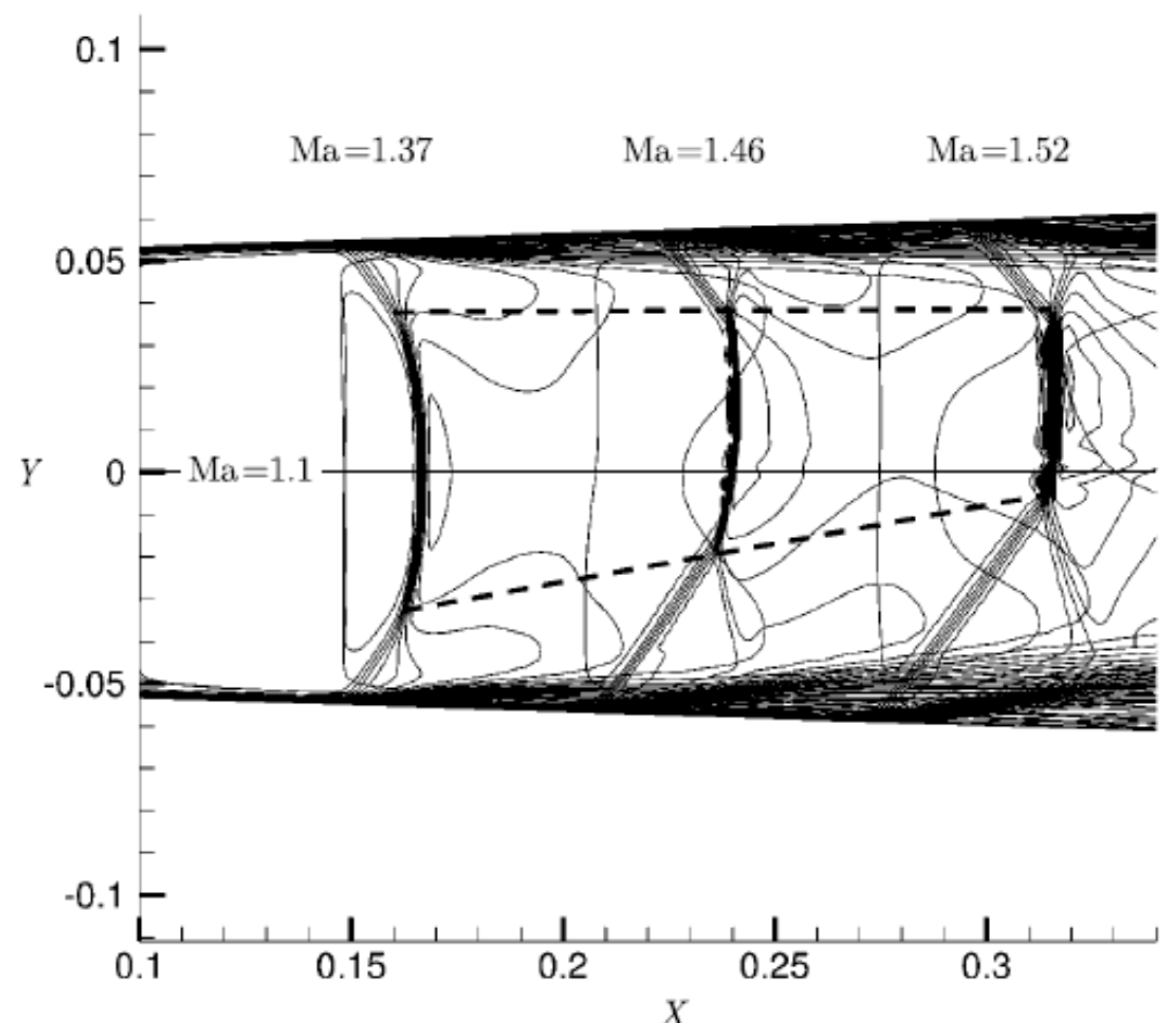
The paper [
34,
35] covers numerical simulations of flow in symmetric nozzle of divergence angle in the range from 2° to 6° and Mach number upstream the shock values from 1.1 to 1.41. On the basis of numerical simulations the authors conclude that in a symmetric nozzle the flow changes to asymmetric beyond some value of divergence angle and Mach number, like in
Figure 4. It is interesting that in the chosen flow configuration (
Figure 4) the asymmetry develops along one side of the nozzle.
Based on the numerical results, the authors of [
34] give the concept of the ‘division point’, that we use now in our present paper for the analysis of experimental results. They also comment on the fact that in CFD results the appearing asymmetry is always in the same direction. This is an effect of small numerical aspects, truncation errors or approximations, which in numerical simulations are deterministic. The authors of [
34] also show that changing the vertical axis orientation changes the direction of asymmetry.
5. Results
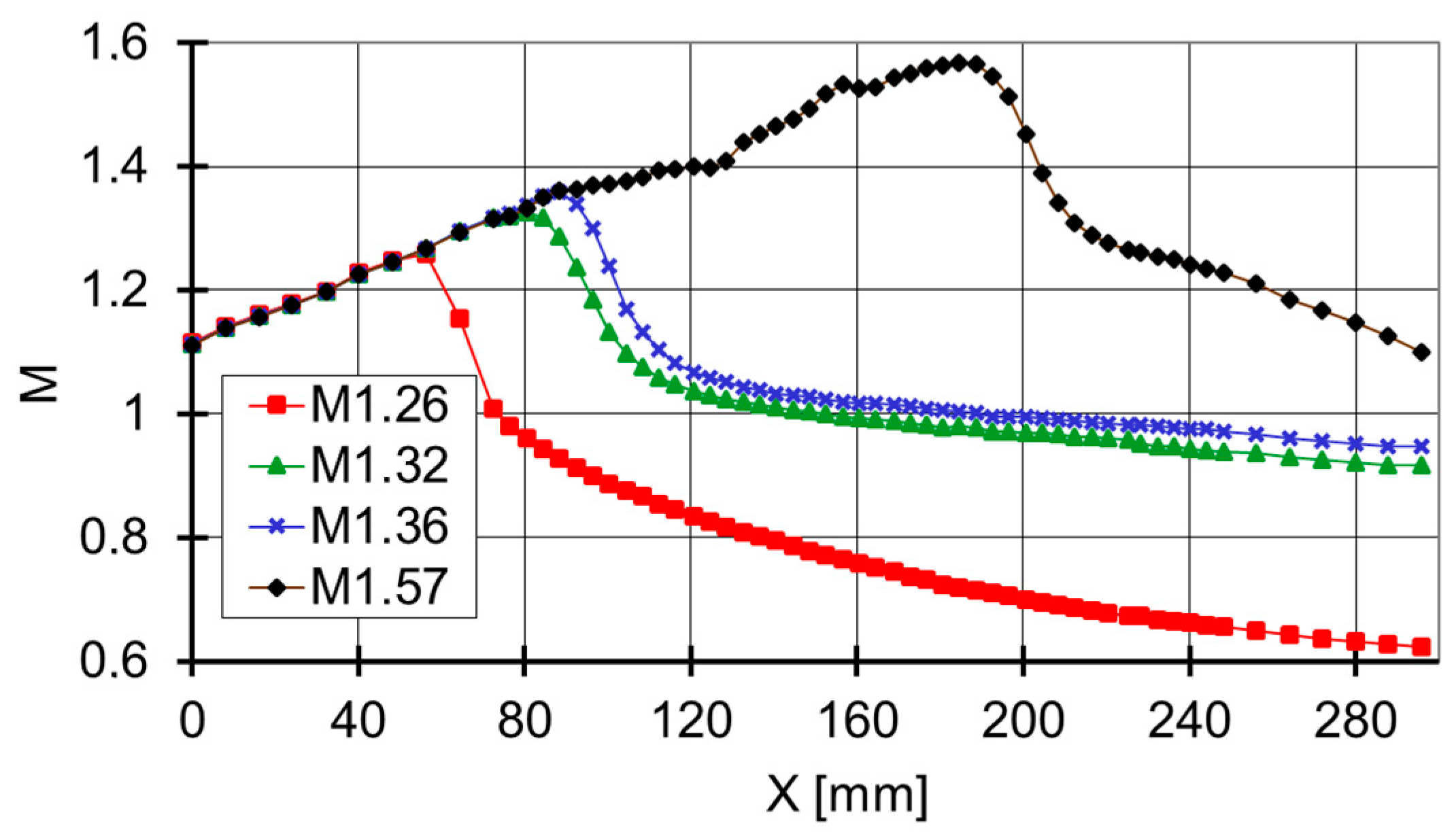
Measured pressure distributions in terms of isentropic Mach number on the bottom wall of the nozzle are presented in
Figure 5 for four chosen cases.
Prior to the shock wave location, all the points follow exactly the same curve, resulting from the nozzle shape. Shock wave presence causes significant Mach number drop. Its location does not display any influence on the Mach number distribution upstream the shock wave. Downstream the shock location a further deceleration towards the nozzle exit takes place.
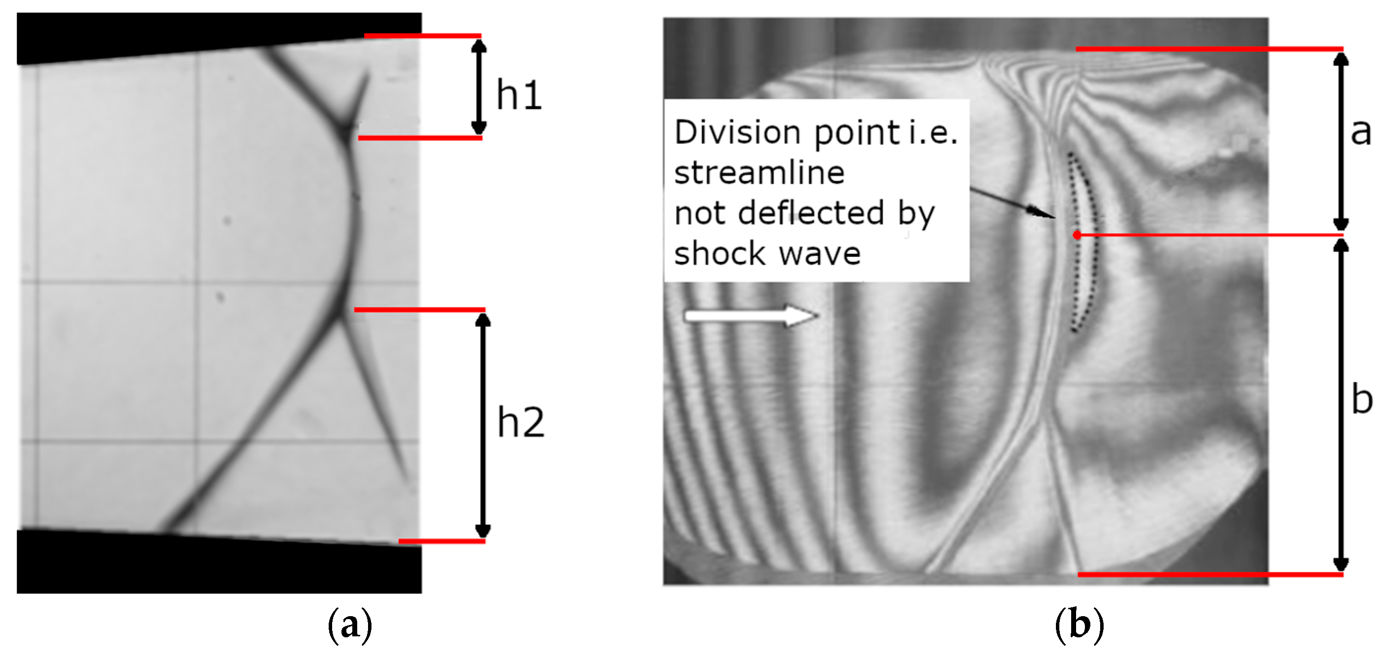
Schlieren photographs (
Figure 6a) and interferograms (
Figure 6b) were the backbone for the investigation of flow topology of the system. The height of the top λ-foot ‘h1’ and the height of bottom λ-foot ‘h2’ are illustrated in
Figure 6a.
In order to parametrize the shock waves topology a new term, the ‘division point’ was introduced. It is defined as the position of the point on a shock wave being perpendicular to the local flow velocity direction. The shock between both triple points is oblique but of the strong type, so it looks nearly normal all over. But it is normal only in one point between triple points. In this particular point the shock is the strongest and therefore the density jump is maximal. Downstream the shock wave therefore, a maximum of density is built-up which is indicated by the ‘looped’ fringe line. This closed line is stretched along the shock because of weak variation of the shock intensity. The centre of this closed fringe line is the place where the dividing streamline is passing through. In the symmetric flow case this line is the geometrical central line of the nozzle.
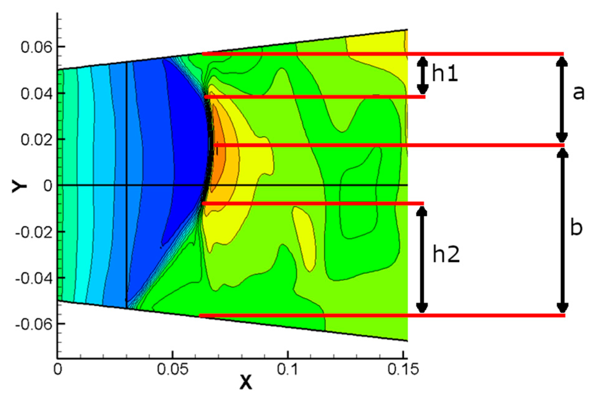
Analogical parameters were determined on the basis of numerical results from Mach number contours, presented in
Figure 7.
The ‘normalised heights’ (‘q’—ratios of shock wave triple point height and corresponding height of the ‘division point’ position) of the top ‘h1/a’ and bottom ‘h2/b’ λ-feet are given in
Table 2.
The values given in
Table 2 show that with error smaller than 1.5% the normalized height of the top and bottom λ-feet remain the same also in asymmetric flows. This observation is confirmed in both experimental and CFD results. The transition from symmetric to asymmetric flow topology is illustrated in
Table 2 in terms of the size of normalized λ-feet ‘q’ as a function of Mach number upstream the shock wave.
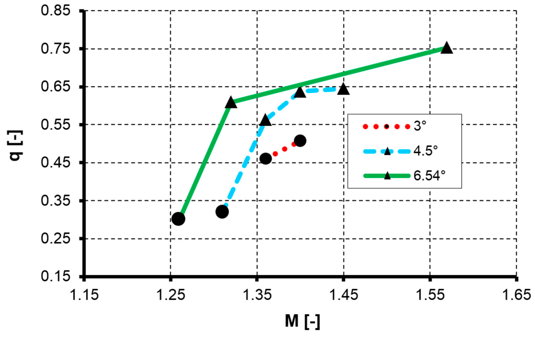
Each curve in
Figure 8 corresponds to a different divergence angle of the nozzle. The shape of the marker indicates the presence of the symmetry. Circle means a symmetric flow, while the triangle denotes the asymmetric one. There is a clear tendency that the symmetry breaks as the Mach number upstream the shock increases, and also when the angle of nozzle divergence increases. If these two are sufficiently high, the asymmetry is likely to appear. For adequately high nozzle divergence angle the symmetry tends to break when the reversed flow caused by the separation becomes noticeable. At this point this complex system of flow with shock waves is looking for a new stable topology.
6. Discussion
The existence of an asymmetric system in a symmetric flow is very confusing and counter-intuitive. One would expect that the top and bottom shock systems being mirror copies with both λ-feet exactly of the same height and the streamline of no deflection (normal shock) located in the axis of the nozzle (‘h1’ = ‘h2’ and ‘a’ = ‘b’). It is illustrated schematically in
Figure 9a. This is true only up to a certain Mach number value.
In the carried out experiments the flow is symmetric for low Mach number and low δ angle. However, for higher Mach number and δ angle values, the flow is not symmetric any more. The flow pattern changes to one depicted in
Figure 9b. In asymmetric cases the λ-feet height and distance from wall to the division line are different for the top and the bottom wall (‘a’ ≠ ‘b’ and ‘h1’ ≠ ‘h2’). The break of symmetry can be caused by either increase of Mach number or by increase of nozzle divergence angle. As the number of cases considered here is relatively low, further research is required to give a more precise insight of the influence of Mach number and divergence angle on the extent of symmetry zone.
On the basis of the results presented, we put forward a hypothesis that after topological symmetry of the flow breaks, the ‘normalised’ symmetry of λ-feet remains in the flow. The ‘physical’ understanding of symmetry expressed by normalising the height of λ-feet by the position of the division line takes into account not just geometrical size of the λ-feet but also the topology of the flow. We claim and have proven that the system of λ-feet is symmetric with reference to the position of normal shock wave position marked as ‘division line’ in
Figure 9b. This ‘division line’ is the streamline perpendicular to the shock wave. In symmetric case this is the geometrical centre line of the nozzle. In the case when geometrical symmetry of the flow is broken, this line is shifted towards one of the nozzle walls: either top or bottom one. This line fixes the heights of two parts that the flow is divided into. In internal flows the height of the channel is a significant factor influencing the size of the λ-foot because the shock wave–boundary layer interaction is constrained in a nozzle.


