Article

Stable Symmetric Matrix Form Framework for the Elastic Wave Equation Combined with Perfectly Matched Layer and Discretized in the Curve Domain

1
College of Aerospace and Civil Engineering, Harbin Engineering University, Harbin 150001, China
2
Key Laboratory of Advanced Material of Ship and Mechanics, Ministry of Industry and Information Technology, Harbin Engineering University, Harbin 150001, China
*
Author to whom correspondence should be addressed.
Symmetry 2020, 12(2), 202; https://doi.org/10.3390/sym12020202
Submission received: 28 December 2019 / Revised: 16 January 2020 / Accepted: 18 January 2020 / Published: 1 February 2020

Abstract

:
In this paper, we present a stable and accurate high-order methodology for the symmetric matrix form (SMF) of the elastic wave equation. We use an accurate high-order upwind finite difference method to define spatial discretization. Then, an efficient complex frequency-shifted (CFS) unsplit multi-axis perfectly matched layer (MPML) is implemented using the auxiliary differential equation (ADE) that is used to build higher-order time schemes for elastodynamics in the unbounded curve domain. It is derived to be compatible with SMF. The SMF framework has a general form of a hyperbolic partial differential equation (PDE) that can be expanded to different dimensions (2D, 3D) or different wave modal (SH, P-SV) without requiring significant modifications owing to a simplified process of derivation and programming. Subsequently, an energy analysis on the framework combined with initial boundary value problems is conducted, and the stability analysis can be extended to a semi-discrete approximation similarly. Thus, we propose a semi-discrete approximation based on ADE CFS-MPML in which the curve domain is discretized using the upwind summation-by-parts (SBP) operators, and where the boundary conditions are enforced weakly using the simultaneous approximation terms (SAT). The proposed method’s robustness and adequacy are illustrated by conducting several numerical simulations.

1. Introduction

In seismology, as well as in many other applications, such as acoustics, oceanography, and electromagnetics, a number of numerical methods to simulate elastic wave propagation have been developed. In general, the elastic wave equation can be discretized using various approaches, such as the finite difference method (FDM) [1,2,3], finite element method (FEM) [4,5], spectral element method (SEM) [6], boundary element method (BEM) [7,8], discontinuous Galerkin method (DGM) [9], and others. Each of these methods has advantages, as well as drawbacks. FDM is successfully applied to solving the problems related to wave propagation and has been widely used in the field of seismic engineering, due to its high efficiency and ability to simulate complex media, such as layered ones. However, it is difficult to handle complex geometry, specifically with regard to the staggered grid method [10]. In addition, several methods related to FDM have difficulties in ensuring long-time stability within the spatial and temporal domain [11]. These drawbacks impose significant limitations to the simulation of large-scale, long-period, and undulating media. Therefore, a numerical method ensuring time and spatial stability is proposed.
Unlike the first- and second-order methods, higher-order FDMs (HOFDMs) can effectively reduce the degree of freedom required to simulate wave propagation. Therefore, HOFDMs are able to capture the wave-dominated phenomena, such as elastic wave propagation, more efficiently, as for a given error tolerance, the number of grid nodes can be reduced substantially and in several dimensions, and thereby, one may significantly decrease the computing time and memory required by orders of magnitude [12]. However, one of the drawbacks of higher-order methods is their relative complexity, both in terms of derivation of formulas and programming implementation. Moreover, the larger amount of programming work is required during the simulation, meaning that a program has to perform more calculations, and more calls per grid node are required. It is deemed that such methods may become more broadly appealing and applied more widely if the associated complexity can be reduced.
The main purpose of the present study is to develop a stable HOFDM for the elastic wave equations both in 2D and 3D curve domains, and to facilitate an implementation procedure to be as simple as possible by establishing a generic framework under the premise. One of the appropriate HOFDMs combining the initial boundary value conditions is to apply summation-by-parts (SBP) [13,14,15,16,17] operators to approximate derivatives of the spatial domain together with weak enforcement of boundary and interface conditions using the simultaneous-approximation-term (SAT) [11,18] method, or the projection method [19,20,21]. The SBP-SAT methodology can be used to provide a strictly stable proof using the energy method that ensures the robustness within the spatial and temporal domain. Some review papers of SBP operators and examples of SBP-SAT can be found in References [22,23,24,25,26].
The basic theory about the first-derivative SBP operators was proposed by Kreiss and Scherer [13] seeking to transform the higher-order methods into a systematic means of proving stability through the energy method [27]. The predominant concept of SBP operators is to mimic the integration-by-parts (IBP) property, so that stability of a discretization framework can be proved by using the energy method similarly to the case of the continuous problems. Initially introduced SBP operators principally have been developed in the context of HOFDMs, where the nodal distribution in a computational space is uniform. A matrix of SBP operators has periodically centered difference stencils in the interior grid nodes and specific one-sided ones near the boundary grid nodes to maintain the SBP property. SBP introduced above can be referred to as a classical SBP operator. Recently, the theory of classical SBP operators has been extended to a broader set of operators, for instance, upwind SBP operators [28,29], staggered and upwind SBP operators [30], generalized SBP operators [31,32,33], and multi-dimensional SBP operators [34,35]. Newly proposed SBP operators have new properties not presented in the classical SBP operators. A matrix of generalized SBP operators can use non-repeating difference stencils in the interior grid nodes that can be non-uniform depending on the distribution of grid nodes. Additionally, generalized SBP operators may exclude one or both boundary nodes. Multi-dimensional SBP operators can avoid dimension expansion in the form of tensor products. Upwind operators can naturally introduce artificial dissipation when combined with flux-splitting techniques for the hyperbolic system.
The SBP-SAT methodology has many useful properties, and one of them is to facilitate the derivation of higher-order spatial discretizations that are provably time-stable using a rather straightforward approach based on the energy method, in which the procedure is similar to the energy method in the continuous case. Another property is that the SBP-SAT methodology can handle the boundary condition in a flexible way, and the boundaries contain those of the computational domain and of interfaces between blocks, in which the blocks are obtained by dividing the computational domain [36]. Referring to this property, an extremely large computational domain can be simulated by dividing the domain into several blocks of the suitable size. Then, simulation can proceed within blocks instead of in the whole computational domain, so that it can greatly alleviate the computer memory consumption. Additionally, an approximation of the derivative in each of the blocks is strictly determined by the solution in the particular block, and interfaces of blocks play the role of data transfer and assignment tools. Therefore, using the SBP-SAT methodology, wave propagation in a computational domain with special shapes can be simulated, which is difficult to achieve using the traditional FDMs, as it is shown in the conducted numerical simulation. Moreover, the interface does not have to be continuous, so that a geometric discontinuity can be simulated intentionally. More detailed contents on the SBP-SAT methodology can be found in Reference [37].
Numerical methods require the domain of simulation to be divided into a finite number of nodes or elements, as it is difficult to simulate elastic wave propagation in a finite domain without employing boundaries to prevent spurious wave reflections back into the computational domain. In the elastodynamic simulation, a wide variety of absorbing layers and boundary conditions have been developed to truncate these domains and “absorb” the outgoing waves as much as possible to simulate the wave motion in finite computational domains (e.g., sponge zone [38,39], SMART layers [40], paraxial conditions [41,42], continued fraction conditions [43], transmitting boundary conditions [44,45], viscous boundary conditions [46,47], viscous-spring artificial boundary conditions [48], optimized boundary conditions [49], etc.). In addition, the perfectly matched layer (PML) [50,51,52,53], and high-order absorbing boundary conditions (ABCs) [54,55,56] are now the most commonly used approaches to considerably limit spurious numerical reflections.
Considering a framework based on the SBP-SAT methodology, a suitable way to avoid artificial reflection is to impose characteristic BC expressed in terms of physical parameters of inflow and outflow, which represents a well-proven, first-order accurate non-reflecting BC. In this case, the energy method is still effective for the semi-approximation system leading to a well-proven approximation [57,58,59,60]. Even though the stability of this framework can be guaranteed in an acceptable manner, the reflected wave generated by the non-reflecting BC may cause continuous perturbations within the wavefield. Consequently, the wavefield may be distorted by the reflected wave in a large-scale or long-time simulation. This adverse effect can be corrected using PML. One of the advantages of PML is that it can control the attenuation effect of waves by changing the number of absorbing layers or damping functions in case of making waves attenuated as much as possible during the absorption. In the present paper, we combine PML and the SBP-SAT methodology to facilitate wave absorption at the boundaries. Description of frameworks utilizing SBP-SAT to discrete PML equations can be found in several papers [61,62,63,64].
In most cases, PML has only one damping coefficient in the direction perpendicular to PML. Even though the simulations of modeling using PML provide a stable and satisfying result in the rectangular computational domains or isotropic medium, a well-known problem of PML and its variants/improvements is that the simulations of modeling using PML provide unstable results in certain kinds of the curve domains or anisotropic medium in terms of long-time wave propagation. The instability problems of PML were analyzed by Bécache et al. [65] from a theoretical point of view and found that stability is related to the relative direction of the group velocity and wavenumber, which was defined as “slowness vector.” Meza-Fajardo and Papageorgiou [66] explained the stability of PML referring to the eigenvalues of the coefficient matrix in the frequency domain, implying that a system is unstable when eigenvalues have positive real part roots. To mitigate this problem, they added appropriate non-zero damping coefficients to PML in the directions both parallel with and perpendicular to the PML/non-PML interfaces simultaneously. They also proposed the damping ratio defined as a ratio between the PML coefficients along with the directions parallel with and perpendicular to the PML/non-PML interfaces referred to as multi-axial PML (MPML). More details on MPML can be found in several related papers [67,68,69,70].
At present, a combination of the SBP-SAT methodology with PML is still mostly applied to the rectangular domain. However, several researchers combine the SBP-SAT methodology with MPML. In seismology, constructing a framework combining SBP-SAT and MPML is of great significance to simulate the propagation of the elastic wave in complex media and in models with complex geometric surfaces. Overall, the most applicable framework for the elastic wave equation is discretized in the form of full expansion. The discretization framework for the elastic wave equation in a different modal (SH, P-SV) or in different dimensions (2D, 3D) is rather different as it implies discrete each element of the elastic wave equation (every velocity and stress in the corresponding equation). The formula will be more complicated in the case of discretization in the curve domain for the Jacobian matrix, and the chain rules are introduced to reduce the generality of formula derivation and programming.
To address this situation, a generic representation of the elastic wave equation, referred to as symmetric matrix form (SMF), is introduced. Using SMF, a framework for the elastic wave equation is cast into the matrix form, and then the discretization can be treated in a generic system. Therefore, the expression of the SMF framework requires generic programming as well. Additionally, a generic stable discretization of SMF in the curve domain can be developed considering a similar framework in the regular domain, and this property has a positive effect on simplification of the formula derivation and program compilation, which can allow avoiding the introduction of direction vectors and the traction effect on the velocity and stress. The proposed framework is, therefore, applicable to a wide range of elastic wave equations.
The remainder of this paper is organized as follows. In Section 2, the SMF of the elastic wave equation in 3D is formulated. It is shown that it can be further extended in the curve domain and then, the well-posed BCs of SMF of the elastic wave equations are established. Thereafter, in Section 3, we propose applying MPML for SMF of the elastic wave equations and present the results of the stability analysis in continuous cases. A semi-discrete SBP-SAT methodology is presented in Section 4. The results of the stability analysis within a discrete norm are discussed in Section 5. It should be noted that the upwind SBP operators are used in this study. Numerical tests are presented in Section 6. Subsequently, conclusions are drawn, and the future research directions are presented in Section 7.

2. SMF of Elastic Wave Equations

In this paper, a 3D isotropic elastic medium is considered. Then, the curve geometry is handled through the use of curvilinear transformation in terms of the curve physical domain that can be mapped to the computational domain represented as a regular block. This corresponds to the regular computational domain of PML, and the FDMs are applied.

2.1. Wave Equation Symmetrization

Consider the Cartesian coordinates of a 3D spatial domain defined by (x, y, z) and t denotes the time variable, the first-order elastic wave equation for the stress-velocity formulation is given by
S σ x x t σ y y t σ z z t σ x y t σ x z t σ y x t ρ v x t ρ v y t ρ v z t = v x x v y y v z z v x y + v y x v x z + v z x v y z + v z y σ x x x + σ x y y + σ x z z σ x y x + σ y y y + σ y z z σ x z x + σ y z y + σ z z z ,
where σ = σ x x , σ y y , σ z z , σ x y , σ x z , σ y z T is the stress vector and v = v x , v y , v z T is the particle velocity vector. ρ is the density of elastic medium and S is the compliance matrix. Note that S = C 1 , where C = C T is the stiffness matrix. Here, we show that the 3D elastic wave equations can be transformed into SMF. First, Equation (1) can be written as
A ˜ 0 U ˜ t = A ˜ x U ˜ x + A ˜ y U ˜ y + A ˜ z U ˜ z ,
where
U ˜ = σ x x ρ , σ y y ρ , σ z z ρ , σ x y ρ , σ x z ρ , σ y z ρ , v x , v y , v z T ,
and the parameter matrices are
A ˜ 0 = a b b 0 0 0 0 0 0 b a b 0 0 0 0 0 0 b b a 0 0 0 0 0 0 0 0 0 c 0 0 0 0 0 0 0 0 0 c 0 0 0 0 0 0 0 0 0 c 0 0 0 0 0 0 0 0 0 1 0 0 0 0 0 0 0 0 0 1 0 0 0 0 0 0 0 0 0 0 , A ˜ x = 0 0 0 0 0 0 1 0 0 0 0 0 0 0 0 0 0 0 0 0 0 0 0 0 0 0 0 0 0 0 0 0 0 0 1 0 0 0 0 0 0 0 0 0 1 0 0 0 0 0 0 0 0 0 1 0 0 0 0 0 0 0 0 0 0 0 1 0 0 0 0 0 0 0 0 0 1 0 0 0 0 , A ˜ y = 0 0 0 0 0 0 0 0 0 0 0 0 0 0 0 0 1 0 0 0 0 0 0 0 0 0 0 0 0 0 0 0 0 1 0 0 0 0 0 0 0 0 0 0 0 0 0 0 0 0 0 0 0 1 0 0 0 1 0 0 0 0 0 0 1 0 0 0 0 0 0 0 0 0 0 0 0 1 0 0 0 , A ˜ z = 0 0 0 0 0 0 0 0 0 0 0 0 0 0 0 0 0 0 0 0 0 0 0 0 0 0 1 0 0 0 0 0 0 0 0 0 0 0 0 0 0 0 1 0 0 0 0 0 0 0 0 0 1 0 0 0 0 0 1 0 0 0 0 0 0 0 0 0 1 0 0 0 0 0 1 0 0 0 0 0 0
For convenience, we use the longitudinal and transverse medium wave speed as material properties.
c p = λ + 2 μ ρ c s = μ ρ
Then the elements of A ˜ 0 can be written as
a = c p 2 c s 2 c s 2 3 c p 2 4 c s 2 , b = c p 2 2 c s 2 c s 2 6 c p 2 8 c s 2 , c = 1 c s 2 .
As A ˜ 0 is positive definite, ansatz A ˜ 0 = P T Λ P . Thus, we have
Λ = 1 3 c p 2 4 c s 2 1 2 c s 2 1 2 c s 2 1 / c s 2 1 / c s 2 1 / c s 2 , P = 1 3 1 3 1 3 0 0 0 1 2 1 2 0 0 0 0 1 6 1 6 2 3 0 0 0 0 0 0 1 0 0 0 0 0 0 1 0 0 0 0 0 0 1 ,
P is an orthonormal matrix that satisfying P T P = I . By denoting
M = P T Λ 1 / 2 P M 1 = P T Λ 1 / 2 P .
Therefore, a symmetric positive definite matrix M can be calculated
M = P T Λ 1 / 2 P = m 1 m 2 m 2 0 0 0 0 0 0 m 2 m 1 m 2 0 0 0 0 0 0 m 2 m 2 m 1 0 0 0 0 0 0 0 0 0 m 3 0 0 0 0 0 0 0 0 0 m 3 0 0 0 0 0 0 0 0 0 m 3 0 0 0 0 0 0 0 0 0 1 0 0 0 0 0 0 0 0 0 1 0 0 0 0 0 0 0 0 0 1 ,
where
m 1 = 1 3 2 2 c s + 3 c p 2 4 c s 2 m 2 = 1 3 2 c s + 3 c p 2 4 c s 2 m 3 = c s
Note that c p = m 1 2 + 2 m 2 2 . Pre-multiply M from Equation (2) yields
U t = A x U x + A y U y + A z U z ,
where U = M 1 U ˜ , and
A x = 0 0 0 0 0 0 m 1 0 0 0 0 0 0 0 0 m 2 0 0 0 0 0 0 0 0 m 2 0 0 0 0 0 0 0 0 0 m 3 0 0 0 0 0 0 0 0 0 m 3 0 0 0 0 0 0 0 0 0 m 1 m 2 m 2 0 0 0 0 0 0 0 0 0 m 3 0 0 0 0 0 0 0 0 0 m 3 0 0 0 0 ,
A y = 0 0 0 0 0 0 0 m 2 0 0 0 0 0 0 0 0 m 1 0 0 0 0 0 0 0 0 m 2 0 0 0 0 0 0 0 m 3 0 0 0 0 0 0 0 0 0 0 0 0 0 0 0 0 0 0 0 m 3 0 0 0 m 3 0 0 0 0 0 m 2 m 1 m 2 0 0 0 0 0 0 0 0 0 0 0 m 3 0 0 0 ,
A z = 0 0 0 0 0 0 0 0 m 2 0 0 0 0 0 0 0 0 m 2 0 0 0 0 0 0 0 0 m 1 0 0 0 0 0 0 0 0 0 0 0 0 0 0 0 m 3 0 0 0 0 0 0 0 0 0 m 3 0 0 0 0 0 m 3 0 0 0 0 0 0 0 0 0 m 3 0 0 0 m 2 m 2 m 1 0 0 0 0 0 0 .
So far, the 3D SMF of the elastic wave equation written as the first-order hyperbolic system is derived. In the present paper, strategies to ensure convenience and universality are demonstrated. One of them is the derivation procedure of ABC, where only the incoming variables need to be prescribed on the boundary leading to a well-posed problem. Let us consider the wave propagation, which is perpendicular to the west boundary as an example. To derive the incoming variables of the west boundary, Equation (11) should be transformed into the system.
U ^ t + A ^ x U ^ x + A ^ y U ^ y + A ^ z U ^ z = 0 ,
where the matrix A ^ x is diagonal that can be eigenvalue decomposition, and thus,
A ^ x = T T A x T = c p c s c s c p c s c s 0 0 0 ,
and
T = T , T + , T 0 = m 1 / c p 0 0 m 1 / c p 0 0 m 1 / c p 0 0 m 2 / c p 0 0 m 2 / c p 0 0 m 2 / c p 0 0 m 2 / c p 0 0 m 2 / c p 0 0 m 2 / c p 0 0 0 1 0 0 1 0 0 1 0 0 0 1 0 0 1 0 0 1 0 0 0 0 0 0 0 0 0 1 0 0 1 0 0 1 0 0 0 1 0 0 1 0 0 1 0 0 0 1 0 0 1 0 0 1 .
Therefore, the incoming variables at the west surface can be represented by
p = T T U = m 1 c p U 1 + m 2 c p U 2 + m 2 c p U 3 + U 7 U 4 + U 8 U 5 + U 9 .
Meanwhile, U = M 1 U ˜ U ˜ = M U , using this property, Equation (18) is equivalent to
p = σ x x + ρ c p v x σ x y + ρ c s v y σ x z + ρ c p v z .
Non-reflecting BCs Equation (19) equal to zero are imposed, as no incoming waves propagate through the surface. Moreover, different boundary conditions, such as the free-surface boundary can be defined by using the algebraic relation of incoming and outgoing characteristic variables. Therefore, SMF of the elastic wave equation is used to establish a general formulation that is suitable for the wave propagation in the curve domain. For the curve domain situation, SMF is able to avoid the derivation process of a direction vector or traction in a different direction, which can significantly simplify the complexity of the formulation and programming. In the following subsection, SMF of the elastic wave equation in the curve domain is introduced.

2.2. Curvilinear Coordinates and Coordinate Transformation

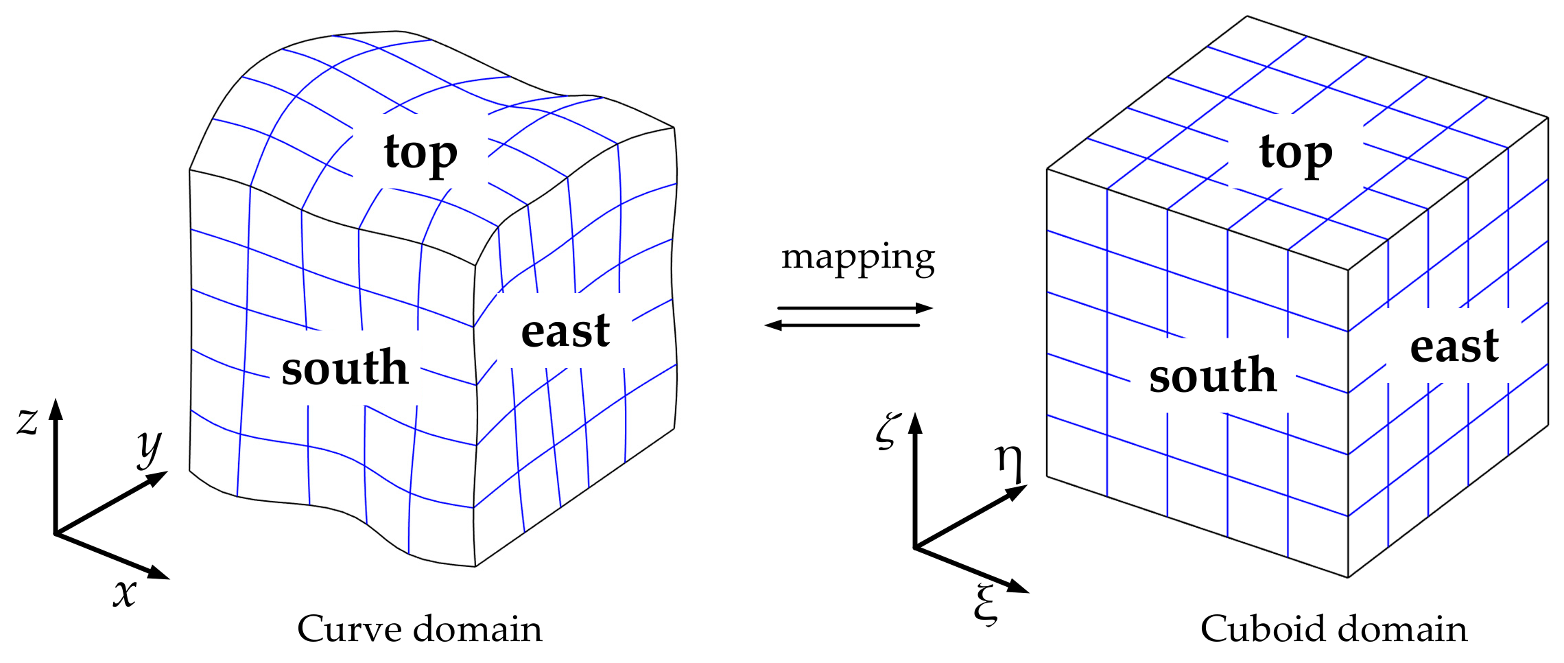
In computations, the actual situation implies that the model discretization uses the curve domain during the simulation, and is more appropriate, compared to when the model discretization is performed using regular grids that have difficulty in handling the issues within the undulating surface or complex medium construction, which deteriorates accuracy and stability. Therefore, the adoption of curvilinear grids is required. Let us consider that the elastic wave propagates in a 3D curve domain Ω x , y , z that can be transformed into a cuboid domain Ω ξ , η , ζ , as shown in Figure 1. In this case, we denote six boundary surfaces as west (W), east (E), south (S), north (N), bottom (B), and top (T). The abbreviations in brackets will be applied to the derivation of the formula. From the stereogram, it can be found that boundary surfaces of west, south, and bottom are opposite to east, north, and top, respectively, which was not shown in Figure 1.
Consider the mapping
x ξ , η , ζ , y ξ , η , ζ , z ξ , η , ζ ξ x , y , z , η x , y , z , ζ x , y , z .
The corresponding Jacobian determinant is defined as,
J = x ξ x η x ζ y ξ y η y ζ z ξ z η z ζ = x ξ y η z ζ + x ζ y ξ z η + x η y ζ z ξ x ξ y ζ z η x η y ξ z ζ x ζ y η z ξ .
Give rise to the derivatives in each direction
J U x = U ξ y η z ζ y ζ z η + U η y ζ z ξ y ξ z ζ + U ζ y ξ z η y η z ξ J U y = U ξ x ζ z η x η z ζ + U η x ξ z ζ x ζ z ξ + U ζ x η z ξ x ξ z η J U z = U ξ x η y ζ x ζ y η + U η x ζ y ξ x ξ y ζ + U ζ x ξ y η x η y ξ .
Using Equation (22), SMF of elastic wave equations in the curve domain can be written as the formulation similar to Equation (11) that in the regular domain.
U t = A ξ U ξ + A η U η + A ζ U ζ ,
where
A ξ = A x J y η z ζ y ζ z η + A y J y ζ z ξ y ξ z ζ + A z J y ξ z η y η z ξ A η = A x J x ζ z η x η z ζ + A y J x ξ z ζ x ζ z ξ + A z J x η z ξ x ξ z η A ζ = A x J x η y ζ x ζ y η + A y J x ζ y ξ x ξ y ζ + A z J x ξ y η x η y ξ .
Obviously, A ξ , A η , A ζ are symmetric matrices, since A x , A y , A z are symmetric as well.

2.3. Well-Posed Boundary Conditions

Since the computational domain cannot be infinite, also to apply other boundary conditions, such as free-surface boundary, wall boundary and the clamped boundary in the framework of the elastic wave equations, we denote six boundary conditions in 3D domain that is west, east, south, north, bottom, top as shown in Figure 1. To simulate seismic wave propagation in the curve domain a free-surface is set at the top boundary. Characteristic boundary conditions, a first-order accurate non-reflecting boundary condition [71], are imposed at the other boundary surfaces.
A ξ ± = T ξ Δ ξ ± Δ ξ 2 T ξ T , A η ± = T η Δ η ± Δ η 2 T η T , A ζ ± = T ζ Δ ζ ± Δ ζ 2 T ζ T ,
where Δ ξ , Δ η , Δ ζ are the diagonal matrices corresponding to A ξ , A η , A ζ . T ξ , T η , T ζ are the eigenvector matrices. Using Equation (25), the characteristic BCs corresponding propagation of the elastic wave in and out of the domain can be written as
p W = T A ξ W T U W , q W = T A ξ W + T U W p E = T A ξ E + T U E , q E = T A ξ E T U E p S = T A η S T U S , q S = T A η S + T U S p N = T A η N + T U N , q N = T A η N T U N p B = T A ζ B T U B , q B = T A ζ B + T U B p T = T A ζ T + T U T , q T = T A ζ T T U T ,
p W , E , S , N , B , T and q W , E , S , N , B , T are the vectors for the incoming and outgoing variables, respectively, at the different boundaries. Here, well-posed BCs conditions expound that only the incoming variables which have the correct quantity need to be prescribed on the boundaries. In this case, the non-reflecting boundary condition and the free-surface boundary conditions can be expressed as an algebraic relation of (26).
p = R q ,
where R is a reflection coefficient with R 1 , 1 . That is, different BCs can be defined through the setting of R. non-reflecting BC is defined by R = 0, and the free-surface BC is given as R = −1. Thus, a generic framework of BCs can be given using the SMF of the elastic wave equations.

3. PML for SMF of the Elastic Wave Equations and Stability Analysis

To obtain a PML system for the corresponding wave equation, complex frequency-shifted (CFS) that introduces a coordinate transform, ξ ξ ˜ , can be used, as equations inside the PML layer have exactly the same form as in the physical domain. The stripe of PML at the positive ξ -axis and the PML-non-PML interface starting at ξ = 0 are considered for convenience. Given a field variable u, we obtain the following:
u ξ = u ξ ˜ ξ ˜ ξ .
Consequently, the complex stretch function is defined as follows:
s ξ ξ = ξ ˜ ξ ,
the Equation (29) can be rewritten as
ξ ˜ = 1 s ξ ( ξ ) ξ .
From the relation Equation (30), we can transform the wave equation in the complex coordinate ξ ˜ , η into the Cartesian coordinate ξ , η , in which the analysis will be conducted. Then, employing the Fourier transform results in the following:
i ω U ^ = 1 s ξ A ξ U ^ ξ + 1 s η A η U ^ η + 1 s ζ A ζ U ^ ζ ,
where U ^ denotes the variable U in the frequency domain. Equation (31) can be transformed into the time domain to obtain the PML equation suitable for the time-domain numerical method. The function of s ξ ( ξ ) has several forms, for standard PML, we obtain the following:
s ξ ( ξ ) = 1 + d ξ ( ξ ) i ω ,
and for generalized PML (GPML), we have
s ξ ( ξ ) = a ξ ( ξ ) 1 + i b ξ ( ξ ) ω ,
for CFS-PML, the function is given by
s ξ ( ξ ) = β ξ ( ξ ) + d ξ ( ξ ) α ξ ( ξ ) + i ω .
In Equation (32) and Equation (34), d ξ ( ξ ) 0 is the damping function, α ξ ( ξ ) 0 is the complex frequency shift and β ξ ( ξ ) 1 is the scaling factor. b ξ ( ξ ) 0 is also the damping function similar to d ξ ( ξ ) , and they are both used for damping the propagating wave exponentially inside PML. a ξ ( ξ ) > 0 is the scaling parameter contributing to either stretching or compressing the coordinate. As the functions introduced above only depend on ξ , we omit the variable for convenience. Equation (34) is adopted in the present study, and then the CFS-PML framework is implemented using auxiliary differential equation (ADE). Moreover, s ξ only has impact in PML, s ξ = 1 in the physical domain in terms of d ξ ( ξ ) = 0 and β ξ ( ξ ) = 1 .
Here, ADE CFS-PML is built through separating the 1 / s ξ into two parts that has the form
1 s ξ = 1 β ξ 1 β ξ d ξ α ξ + i ω β ξ + d ξ .
Therefore, Equation (31) is equivalent to
i ω U ^ = 1 β ξ A ξ U ^ ξ 1 β ξ P ^ ξ + A η U ^ η i ω P ^ ξ = d ξ β ξ A ξ U ^ ξ α ξ + d ξ β ξ P ^ ξ ,
where P ^ is the auxiliary variable transformed into the frequency domain. Equation (36) is the unsplit-field CFS-PML framework in the frequency domain. The corresponding framework of Equation (36) in the time domain is given by,
U t = A ξ U ξ + A η U η + 1 β ξ 1 A ξ U ξ 1 β ξ P ξ P ξ , t = d ξ β ξ A ξ U ξ α ξ + d ξ β ξ P ξ .
Obviously, the PML framework is based on the original wave equations, so that it is easy to implement an existing code with minor necessary changes. Furthermore, SMF of the elastic wave equation can simplify the process of the problem analysis, as well as that of programming, as only U and A are modified to represent the different wave modal and wave dimensions. The PML framework presented above that has one damping function in the direction perpendicular to the stripe of PML is unstable in certain kinds of anisotropic medium or in the curve domain having curvilinear grids distribution. The MPML framework has a form similar to PML in which an additional damping function is implemented along the direction parallel with the stripe of PML. Therefore, the damping ratio defined as a ratio between the damping functions along with the directions parallel with and perpendicular to the stripe of PML, is introduced as follows:
p η / ξ = s η ξ s ξ ξ p ζ / ξ = s ζ ξ s ξ ξ .
Here, ADE CFS-PML is utilized in the main damping direction, and the standard PML is introduced in the additional damping directions, where β = 1 and α = 0 . For convenience, we present MPML located at the west of the physical domain as an example. Similar to Equation (37), the additional damping function in the direction parallel with PML is set to be proportional to the damping function in the direction perpendicular to PML, which can be expressed by the damping ratio.
U t = A ξ U ξ + A η U η + A ζ U ζ + 1 β ξ ξ 1 A ξ U ξ 1 β ξ ξ P ξ ξ P ξ η P ξ ζ W P ξ , t ξ = d ξ ξ β ξ ξ A ξ U ξ α ξ ξ + d ξ ξ β ξ ξ P ξ ξ P ξ , t η = d ξ η A η U η d ξ η P ξ η P ξ , t ζ = d ξ ζ A ζ U ζ d ξ ζ P ξ ζ W
We should note that all functions in square brackets only have an impact in the west stripe of PML, as well as ADE will be eliminated in the physical domain given that less memory usage is needed compared with split-MPL. MPML can be used to stabilize the numerical simulation for anisotropic medium or on curvilinear grids. The framework based on MPML does not differ significantly from the framework based on PML. Furthermore, SMF of the elastic wave equation has the same formulation both in the regular and curve domains. This property can allow simplifying considerably the derivation of the framework by hands, where more work can be done by computational means.

3.1. Energy Analysis of SMF Based on MPML in the Frequency Domain

In this section, the energy analysis is presented for SMF of the elastic wave equations combined with BC. It should be noted that the energy analysis of the SMF framework based on MPML and non-PML requires different procedures. The framework based on MPML cannot derive an analysis estimate in the time domain, while this can be done for the framework without MPML. Nevertheless, these two cases have a similar form in the corresponding domain. To begin with, we take the Fourier transform of (39) in time and remove the auxiliary equations that take the following form:
i ω U ^ = 1 s ξ W A ξ U ^ ξ + 1 s η W A η U η + 1 s ζ W A ζ U ζ .
It should be noted that s η W = s ζ W and s ξ W , s η W , s ζ W are have impact to PML only in the west domain and are removed in the rest of the domain. Pre-multiplying s η W U ^ H and adding the conjugate of the product, then integrating over the domain yields.
s η W i ω U ^ 2 = s η W s ξ W s 1 U ^ H A ξ U ^ d S ξ = 0 ξ = 1 + s 2 U ^ H A η U ^ d S η = 0 η = 1 + s 3 U ^ H A ζ U ^ d S ζ = 0 ζ = 1 = s η W s ξ W B T W ^ + B T E ^ + B T S ^ + B T N ^ + B T B ^ + B T T ^ ,
where s 1 , s 2 , s 3 are bounary surfaces and the boundary terms are
B T W ^ = W U ^ H A ξ + + A ξ U ^ d S = W U ^ H A ξ + U ^ d S 0 B T E ^ = E U ^ H A ξ + + A ξ U ^ d S = E U ^ H A ξ U ^ d S 0 B T S ^ = S U ^ H A η + + A η U ^ d S S U ^ H A η + U ^ d S 0 B T N ^ = N U ^ H A η + + A η U ^ d S = N U ^ H A η U ^ d S 0 B T B ^ = B U ^ H A ζ + + A ζ U ^ d S B U ^ H A ζ + U ^ d S 0 B T T ^ = T U ^ H A ζ + + A ζ U ^ d S = T U ^ H A ζ U ^ d S 0 .
Note that U ^ 2 is the inner product and Equation (42) represents non-reflecting boundaries in the cure domain. For the free-surface BC, take the top boundary surface, or other types of BC, as shown in Equation (27), yields
B T T ^ = T U ^ H A ζ + + A ζ U ^ d S = T U ^ H T A ζ R Δ A ζ + R T + Δ A ζ T A ζ T U ^ d S 0 .
All boundary terms are non-positive, and Re s η W i ω > 0 . Therefore, U ^ 2 0 .

3.2. Energy Analysis of SMF without PML in the Time Domain

The stability of SMF without PML can be proceeded in the time domain using the energy method. The derivation is similar to Section 3.1. Multiplying Equation (23) by U T , setting data to zero and adding its transpose, then integrating over the domain yields
U t T U + U T U t d S = U T A ξ U ξ + U T A η U η + U T A ζ U ζ + U ξ T A ξ U + U η T A η U + U ζ T A ζ U d S
Equation (44) is equivalent to
t U 2 = B T W + B T E + B T S + B T N + B T B + B T T ,
where the boundary terms in the time domain are similar to Equation (42), the bottom boundary as non-reflecting BC and the top boundary as free-surface BC or others are
B T B = B U T A ζ + + A ζ U d S B U T A ζ + U d S 0 B T T = T U T A ζ + + A ζ U d S = T U T T A ζ R Δ A ζ + R T + Δ A ζ T A ζ T U d S 0 .
Equations (46) non-positive so that Equations (45) satisfies the energy estimate. Using SMF, energy analysis can be greatly simplified as a generic system.
4. SBP-SAT Methodology of SMF

4.1. Upwind SBP Operators

In this paper, the differential SBP operators with non-central interior stencils referred to as upwind SBP operators are introduced to perform the discretization of the proposed framework. More details can be found in Reference [29]. Here, a simpler and clearer SBP-SAT methodology for the 1D scalar hyperbolic equation is considered similar to the procedure used for the discretion of the 3D SMF of the elastic wave equation. First, it is necessary to introduce the main definitions. The result at the grid point is stacked as a vector, where u 1 T = u 1 1 , u 1 2 , , u 1 k and u 2 T = u 2 1 , u 2 2 , , u 2 k . The inner product is given by u 1 , u 2 A = x l x r u 1 T A x u 2 d x , A x = A T x > 0 in the domain u 1 , u 2 L x l , x r . Therefore, the corresponding norm can be expressed as u A 2 = u , u A . Here, the computational domain is discretized using the following N+1 equidistant grid points:
x i = x l + i 1 h , i = 1 , 2 , , N + 1 , h = x r x l , N .
Some common vectors are introduced:
e l = 1 , 0 , , 0 T , e r = 0 , 0 , , 1 T , B = e r e r T e l e l T .
The scalar hyperbolic system is given by
u t = A u x , x x L , x R , t 0 ,
here, A = A T is a constant coefficient matrix of size k × k . Pre-multiplying u T then adding its transpose and integrating over the domain yields
u 2 t = u L T A u L u R T A u R ,
where u L , u R are the vector unknown variables at the left and right boundary, respectively. To perform semi-discrete approximation and combine with the upwind SBP operators, an important step is to split into two parts with positive and negative running characteristics, which are referred to as flux splitting. In these cases, we split A into a positive and a negative part as follows: A = A + + A . Meanwhile, the eigenvalues of A + are non-negative, and those of A are non-positive. The purpose of matrix splitting can be realized in several ways. Here, the splitting form of matrices is defined as follows:
A ± = T T Λ + Σ T = A ± R ,
where Λ is the diagonal matrix holds the eigenvalues of A. T is the corresponding eigenvector and Σ is a symmetric positive definite matrix. Note that R is symmetric and positive definite. Hence, the flux-splitting form of the hyperbolic Equation (49) can be written as
u t = A + u x + A u x , x x L , x R , t 0 .
The semi-discrete form of Equation (52) using upwind SBP operators is given by
v t = A + D + v + A D v ,
where v is the approximate solution of u at the corresponding grids. is the Kronecker product. D + = H 1 Q + + B / 2 and D = H 1 Q + B / 2 are the difference operators approximating / x . H is the diagonal matrix which is defined as a discrete norm. Q + + Q T = 0 and Q + + Q + T = S where S is negative semi-definite. Hence, upwind, dual-pair, SBP operators will naturally introduce artificial dissipation.
Using the energy method, the energy estimate in the semi-discrete case can be represented via pre-multiplying Equation (52) with v T I K H and adding the transpose yields
v 2 t = 2 v T R S v + v r T A v r v l T A v l .
That is, the energy estimate is mimicked through the addition of non-positive artificial dissipation. The system is equivalent to a semi-discrete non-split form using a traditional SBP operator with the addition of artificial dissipation. These newly defined SBP operators allow performing significantly more robust and accurate numerical approximations comparing with the traditional SBP operators. Another advantage of the upwind SBP operators is the ability to simulate the point source terms that cause many limitations for the traditional SBP operators to realize the procedure. In this paper, fifth order upwind SBP operators are used, as mentioned in Reference [29].
The SBP-SAT methodology is an efficient approximation that can be used to yield stable and accurate results. In the case of non-PML, the stability of the framework based on SBP-SAT can be proven using the energy method.

4.2. SBP-SAT Methodology of SMF

In this subsection, a semi-discrete approximation of 3D ADE CFS-MPML for SMF of the elastic wave equations is proposed. To begin with, a computation domain is discretized into ( N ξ + 1 ) × ( N η + 1 ) × ( N ζ + 1 ) grids. All corresponding numerical solutions at each grid are stacked into a vector, as well as the auxiliary variables. Define I 9 be the 9 × 9 identity matrix
Upwind SBP operators in 3D are
D ξ = D ξ 1 D I N η I N ζ I 9 D η = I N η D η 1 D I N ζ I 9 D ζ = I N η I N η D ζ 1 D I 9 H ξ η ζ = H ξ H η H ζ I 9 .
The coefficient matrices are determined in 3D yields
A ξ = I ξ I η I ζ A ξ 1 D A η = I ξ I η I ζ A η 1 D A ζ = I ξ I η I ζ A ζ 1 D .
Boundary direction vectors extend to 3D are given as
E W = e l ξ I η I ζ I 9 E E = e r ξ I η I ζ I 9 E S = I ξ e l η I ζ I 9 E N = I ξ e r η I ζ I 9 E B = I ξ I η e l ζ I 9 E T = I ξ I η e r ζ I 9 .
By definition, 3D ADE CFS-MPML for SMF of elastic wave equations utilizing the SBP-SAT methodology can be written as
U t = A ξ + D ξ + U + A ξ D ξ U + A η + D η + U + A η D η U + A ζ + D ζ + U + A ζ D ζ U + 1 β ξ ξ 1 A ξ + D ξ + U + A ξ D ξ U 1 β ξ ξ P ξ ξ P ξ η P ξ ζ W , E + 1 β η η 1 A η + D η + U + A η D η U 1 β η η P η η P η ξ P η ζ S , N + 1 β ξ ξ 1 A ζ + D ζ + U + A ζ D ζ U 1 β ξ ξ P ζ ζ P ζ ξ P ζ η B , T + S A T W + S A T E + S A T S + S A T N + S A T B + S A T T ,
where the auxiliary variables and boundary condition terms are defined as
P ξ , t ξ = d ξ ξ β ξ ξ A ξ + D ξ + U + A ξ D ξ U α ξ ξ + d ξ ξ β ξ ξ P ξ ξ + d ξ ξ β ξ ξ S A T W , E P ξ , t η = d ξ η A η + D η + U + A η D η U d ξ η P ξ η P ξ , t ζ = d ξ ζ A ζ + D ζ + U + A ζ D ζ U d ξ ζ P ξ ζ W , E P η , t η = d η η β η η A η + D η + U + A η D η U α η η + d η η β η η P η η + d η η β η η S A T S , N P η , t ξ = d η ξ A ξ + D ξ + U + A ξ D ξ U d η ξ P η ξ P η , t ζ = d η ζ A ζ + D ζ + U + A ζ D ζ U d η ζ P η ζ S , N P ζ , t ζ = d ζ ζ β ζ ζ A ζ + D ζ + U + A ζ D ζ U α ζ ζ + d ζ ζ β ζ ζ P ζ ζ + d ζ ζ β ζ ζ S A T B , T P ζ , t ξ = d ζ ξ A ξ + D ξ + U + A ξ D ξ U d ζ ξ P ζ ξ P ζ , t η = d ζ η A η + D η + U + A η D η U d ζ η P ζ η B , T ,
and
S A T W = + H ξ 1 E W T A ξ W Δ A ξ W T A ξ W T U W S A T E = H ξ 1 E E T A ξ E + Δ A ξ E + T A ξ E + T U E S A T S = + H η 1 E S T A η S Δ A η S T A η S T U S S A T N = H η 1 E N T A η N + Δ A η N + T A η N + T U N S A T B = + H ζ 1 E B T A ζ B Δ A ζ B T A ζ B T U B S A T T = H ζ 1 E T T A ζ T + Δ A ζ T + T A ζ T + T U T .
In Equation (59), equations of auxiliary variables contain SAT terms, which are referred to as PML stabilizing SAT terms. It is a necessary input to establish numerical stability [63]. In the present paper, this property is demonstrated in the procedure of the energy analysis. Additionally, the SAT terms are identically set equal to zero if BCs Equation (26) are satisfied. The framework of 3D SMF for the elastic wave equation discretized by the SBP-SAT methodology is concise, which can significantly simplify the complexity of the elastic wave equation. Compared to the discretization based on non-SMF framework, programming of Equation (58) also can be greatly simplified, as well as it can be applied to more high-level situations, such as different types of PML, that is, not only MPML, but also classical PML can be defined through the definition of the damping ratios. Non-PML applied to the SMF framework can be demonstrated meaning that is suitable for the classical SBP-SAT system with characteristic boundary conditions. The stability of SBP-SAT without applying PML can be proven using the energy method. The considered scenario is to establish a generic SMF framework that can be switched to PML/MPML and even non-PML cases depending on a concrete problem. In the following section, stability is analyzed in the frequency domain, if the framework is combined with MPML, and in the time domain, if not.

5. Stability Analysis for the Semi-Approximate SMF Framework

In this section, the energy analysis is shown for the SMF framework for the elastic wave equation with the BC in Equation (26). Depending on whether the framework can or cannot be combined with PML, the energy analysis is divided into the framework without PML in the time domain, and the framework with PML in the frequency domain. In these cases, the advantage of the energy analysis is that we can construct stable numerical discretization by mimicking this continuous energy analysis in a discrete setting.

5.1. Stability Analysis for the SMF Framework without PML

The framework without PML equivalent to the classical SBP-SAT formula is considered. The SMF framework presented in the present paper is very flexible and can be used to transform into PML/MPML and even non-PML. The SBP-SAT discretization of SMF in Equation (23) with BCs in Equation (27) can be described as follows:
U t = A ξ + D ξ + U + A ξ D ξ U + A η + D η + U + A η D η U + A ζ + D ζ + U + A ζ D ζ U + S A T W + S A T E + S A T S + S A T N + S A T B + S A T T ,
Multiplying Equation (61) by U T H ξ η ζ and adding the transpose, then integrating over the domain yields
U H ξ η ζ 2 t = 2 U T S ξ H η ζ A ξ + U 2 U T S ξ H η ζ A ξ U + 2 U T S η H ξ ζ A η + U 2 U T S η H ξ ζ A η U + 2 U T S ζ H ξ η A ζ + U 2 U T S ζ H ξ η A ζ U + B T .
The boundary terms are
B T = B T W + B T E + B T S + B T N + B T B + B T T B T W = U W T H η ζ W A ξ W U W + 2 U W T H η ζ W T A ξ W Δ A ξ T A ξ W T U W = U W T H η ζ W T A ξ W + Δ A ξ W + T A ξ W + T U W + U W T H η ζ W T A ξ W Δ A ξ W T A ξ W T U W B T E = U E T H η ζ E A ξ E U E 2 U E T H η ζ E T A ξ E + Δ A ξ E + T A ξ E + T U E = U E T H η ζ E T A ξ E + Δ A ξ E + T A ξ E + T U E + U E T H η ζ E T A ξ E Δ A ξ E T A ξ E T U E B T S = U S T H ξ ζ S A η S U S + 2 U S T H ξ ζ S T A η S Δ A η S T A η S T U S = U S T H ξ ζ S T A η S + Δ A η S + T A η S + T U S + ω S T H ξ ζ S T A η S Δ A η S T A η S T U S B T N = U N T H ξ ζ N A η N U N 2 U N T H ξ ζ T A η N + Δ A η N + T A η N + R T A η N T U N = U N T H ξ ζ N T A η N + Δ A η N + T A η N + T U N + U N T H ξ ζ N T A η N Δ A η N T A η N T U N B T B = U B T H ξ η B A ζ B U B + 2 ω B T H ξ η B T A ζ B Δ A ζ B T A ζ B T U B = U B T H ξ η B T A ζ B + Δ A ζ B + T A ζ B + T U B + ω B T H ξ η B T A ζ B Δ A ζ B T A ζ B T U B B T T = U T T H ξ η T A η T U T 2 U T T H ξ η T A ζ T + Δ A ζ T + T A η T + R T A ζ T T U T = U T T H ξ η T T A ζ T + Δ A ζ T + T A ζ T + T U T + U T T H ξ η T T A ζ T Δ A ζ T T A ζ T T U T ,
where boundary terms are all non-positive. U H ξ η ζ 2 t < 0 is satisfied shows that the framework is stable, since the upwind operators introduce additional artificial damping.

5.2. Stability Analysis for the SMF Framework Using MPML

In this subsection, the process is similar to the continuous case. First, Equation (58) is transformed in the frequency domain, as the energy analysis cannot be used in the time domain. Then, considering analogous to Equation (62) and using the properties of upwind SBP operators and the symmetry of SMF, the stability of Equation (58) can be proved. Transforming Equation (58) in the frequency domain and then inserting an auxiliary differential Equation (59) into Equation (58) yields the following:
i ω U ^ t = 1 s ξ W + 1 s ξ E + 1 s ξ S + 1 s ξ N + 1 s ξ B + 1 s ξ T A ξ + D ξ + + A ξ D ξ U ^ + 1 s η W + 1 s η E + 1 s η S + 1 s η N + 1 s η B + 1 s η T A η + D η + + A η D η U ^ + 1 s ζ W + 1 s ζ E + 1 s ζ S + 1 s ζ N + 1 s ζ B + 1 s ζ T A ζ + D ζ + + A ζ D ζ U ^ + 1 s ξ W S A T ^ W + 1 s ξ E S A T ^ E + 1 s η S S A T ^ S + 1 s η N S A T ^ N + 1 s ζ B S A T ^ B + 1 s ζ T S A T ^ T ,
where
S A T ^ W = + H ξ 1 E W T A ξ W Δ A ξ W T A ξ W T U ^ W S A T ^ E = H ξ 1 E E T A ξ E + Δ A ξ E + T A ξ E + T U ^ E S A T ^ S = + H η 1 E S T A η S Δ A η S T A η S T U ^ S S A T ^ N = H η 1 E N T A η N + Δ A η N + T A η N + T U ^ N S A T ^ B = + H ζ 1 E B T A ζ B Δ A ζ B T A ζ B T U ^ B S A T ^ T = H ζ 1 E T T A ζ T + Δ A ζ T + T A ζ T + T U ^ T .
Here, only the west boundary surface is considered for convenience that other boundary surfaces are treated in the same way. Note that the s ξ W is only effective to the PML in the west domain and vanish in the rest of the domain. That is
i ω s η W U ^ t = s η W s ξ W A ξ + D ξ + + A ξ D ξ U ^ + A η + D η + + A η D η U ^ + A ζ + D ζ + + A ζ D ζ U ^ + s η W s ξ W S A T ^ W .
Pre-multiplying s η W U ^ H and adding the conjugate of the product, then integrating over the domain yields. In this case, define s η W = s ζ W yields
s η W i ω U ^ H ξ η ζ 2 = 2 s η W s ξ W U ^ T S ξ H η ζ A ξ + U ^ 2 s η W s ξ W U ^ T S ξ H η ζ A ξ U ^ + 2 U ^ T S η H ξ ζ A η + U ^ 2 U ^ T S η H ξ ζ A η U ^ + 2 U ^ T S ζ H ξ η A ζ + U ^ 2 U ^ T S ζ H ξ η A ζ U ^ + s η W s ξ W B T ^ W + B T ^ E + B T ^ S + B T ^ N + B T ^ W + B T ^ B + B T ^ T .
The boundary terms are non-positive, and S is negative semi-definite. Therefore, Equation (67) < 0. Here, the left side of the formula in the frequency domain has a high degree of similarity with the left side of the Formula (62) in the time domain. Equation (67) can be transformed into Equation (62) when the non-PML condition is considered as a transition from the frequency domain to the time domain. This is important to build a generic program that can be able to design flexibly according to requirements of simulation.

6. Numerical Experiments

In this section, several numerical examples are presented to demonstrate the generic, feasible, and flexible characteristics of the SMF framework. First, a numerical experiment considering PML/MPML/non-PML is implemented to show the advantage of the generic SMF framework, which can be easily switched between PML/MPML and non-PML. In this experiment, the necessity of applying MPML in some cases can be observed. Then, a model of the circular domain with the anisotropic medium is simulated using a multi-block. Finally, elastic wave propagation in a 3D curve domain with a free-surface boundary is simulated. The first two examples are simulated in the 2D case to display the implementation effect of the proposed framework better.

6.1. Comparison among PML/MPML/Non-PML in the Curve Domain

In this simulation, the necessity of MPML is verified only in terms of the ability of MPML to stabilize the result in the case of using PML that may lead to an unstable simulation. Below, a curve domain is presented, the contour of the curve physical domain is listed in Table A1.
For the PML damping coefficients, we set
d ( θ ) = d max θ δ h ¯ 2 , i f θ P M L 0 , i f θ P M L ,
d max 0 denotes the damping strength as Duru et al. [63].
d max = 4 v max 2 h ¯ ln 1 t o l ,
here, h ¯ is the width of PML, and δ is the coordinate for the PML/non-PML interface. The damping coefficient parallel with PML is defined as p r d ( θ ) in which p r is referred to as the damping ratio in Equation (38). The framework becomes ADE CFS-PML when we set p r = 0 . Properties and discretization parameters for simulation are presented in Table 1. It should be noted that x c , y c represent the central coordinate of the domain.
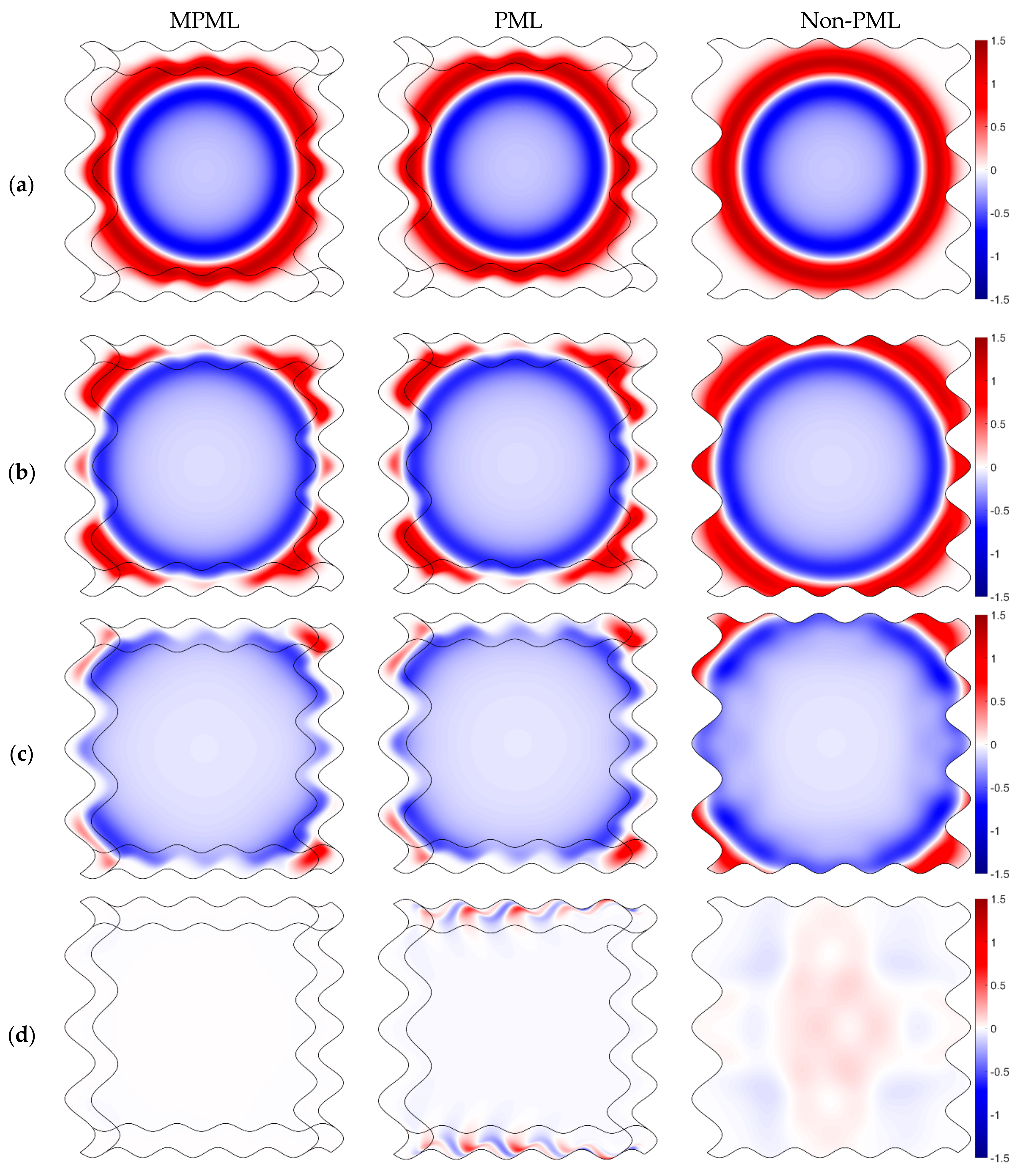
The stripe of PML corresponds to the boundaries of the curve domain. In practice, the framework of MPML and non-PML can provide stable results, while the framework of PML is incapable of generating them (see Figure 2e). The elastic wave has been damped in the MPML and PML zone, as a wave propagates to the PML/MPML zone (see Figure 2a,b). In Figure 2c, the reflected wave is not discovered in the first two figures, which indicates that PML can absorb the direct wave and suppress the reflected one. A stable simulation for the SMF framework based on SBP-SAT with non-PML can be obtained, however, weakly reflected waves generated at the non-reflecting BCs cause a continuous disturbance to the wavefield, which may cause its distortion, as the undesirable wave propagates to the medium internal. This phenomenon is more prominent at the time of 1.25 s (see Figure 2d), as the direct wave has propagated out of the domain. However, eventually, the wavefield is going to stabilize. The instability can be clearly observed for the framework based on PML at the time = 1.25 s, and the instability simulation is started in the PML zone. Although the stability analysis is satisfied with the framework based on PML, it may still provide unstable results. This characteristic was also reflected in the paper [52]. Accordingly, MPML is able to stabilize the simulation in terms of the curve domain that has the properties of the anisotropic medium. Therefore, the framework based on SMF for the elastic wave equation combined with MPML has important applications in the field of earthquake engineering, such as the simulation of models with a complex surface or cracks. Moreover, it can simplify the program compilation and enhance the universality of the program as far as possible.
The energy of simulation using MPML and PML at different instants of time is shown in Figure 3. Here, the decay of energy and long-time stability is verified. However, instability of the wavefield for PML without auxiliary damping coefficients is observed. The energy obtained by using SBP-SAT with the non-PML condition provides a stable result that is suitable for the long-time simulation. However, continuous disturbance of the wavefield is caused by the reflected wave that may distort the wavefield, as the undesirable wave propagates to the medium internal.
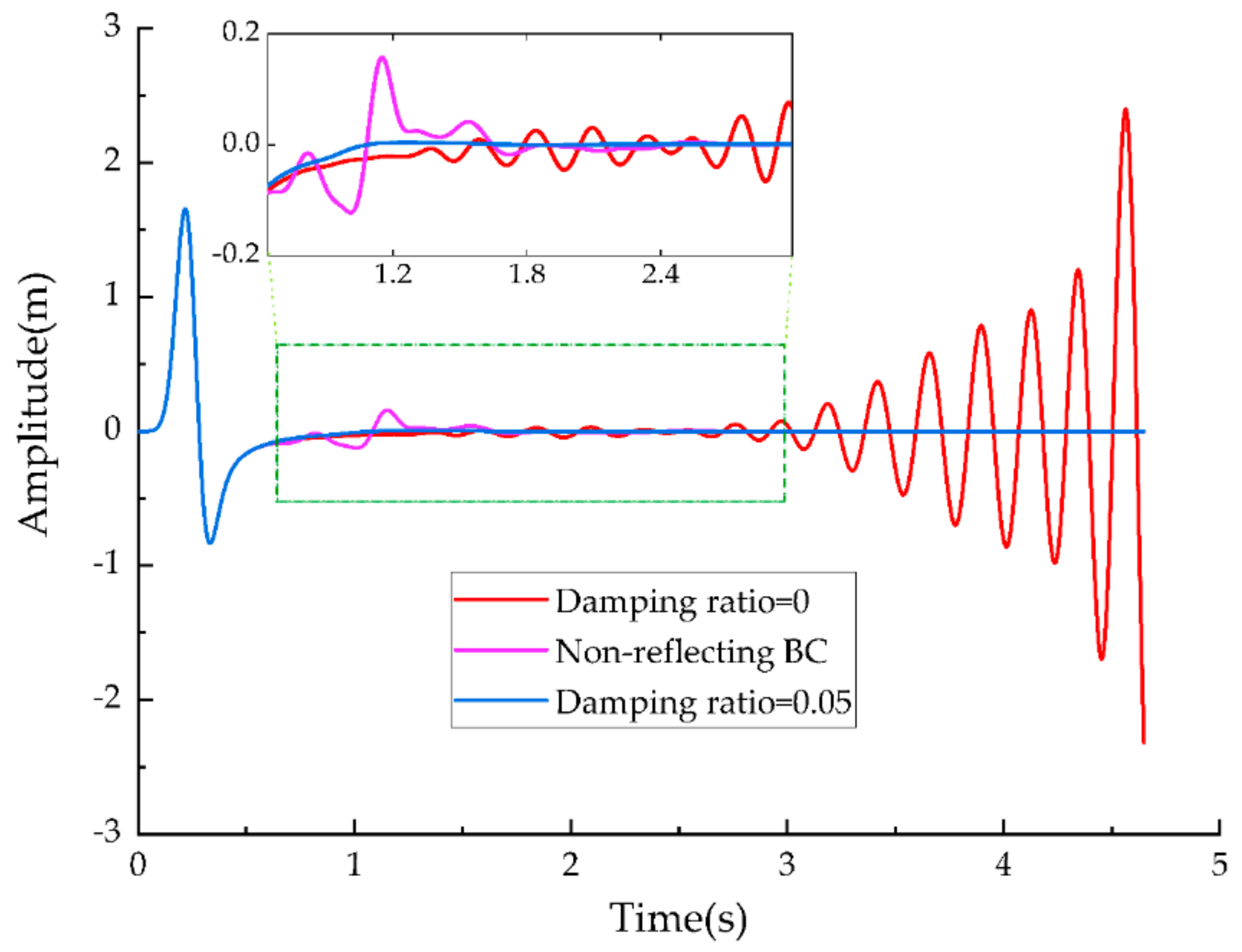
To observe the absorption effect on the frameworks based on MPML/PML/non-PML, the amplitude of velocity at the node grid (row, column) is exhibited (see Figure 4). The wavefield used in the framework of non-reflecting BC is perturbed for a long time, and the reflections become more prominent than the wavefield based on the framework of MPML. Whereas, the stability of this method is ensured. It should be noted that the generation of the reflected wave can be suppressed using the framework of PML at the beginning, however, the simulation will be unstable with the increase in the simulation time. It indicates that PML may deteriorate the stability of the original numerical framework; however, potentially, it is not confined to the SBP-SAT methodology. The reason for the instability of the results may be due to the fact that the curve domain has similar properties to anisotropic media, which leads to the unstable results of the numerical simulation of PML in the curve domain.

6.2. Framework for the P-SV Wave Modal Corresponding to the Anisotropy Medium and the Circular Domain

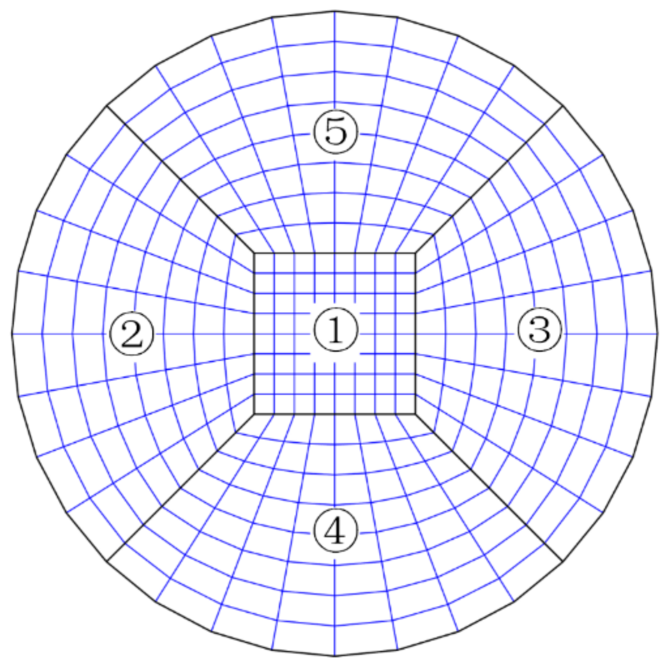
Although the SMF presented here is based on isotropic media, and thus, has a simply stiffness matrix, the elastic wave equation for anisotropic media can be similarly cast in its framework. The solution of the stiffness matrix characteristic system is very difficult to describe with algebraic expressions or in the form of flexibility matrix. However, the SMF of elastic wave equations in anisotropic media can be established by a numerical solver, i.e., a purely numerical approach is considered. Using the SBP-SAT methodology, a model of the circular domain can be simulated by HOFDMs, which is difficult to achieve using the traditional FDMs. Here, the circular domain is divided into five blocks, and numbering of each block is presented in Figure 5, the solid black circle line on the edge is the non-reflecting BCs, and the solid black lines inside are the boundaries of the interface of blocks. Each block is computed independently during a simulation time, and the data related to nodes can be passed through the boundaries of the interface using the SBP-SAT methodology. Properties and discretization parameters for simulation are presented in Table 2, and the curve physical domain is listed in Table A2.
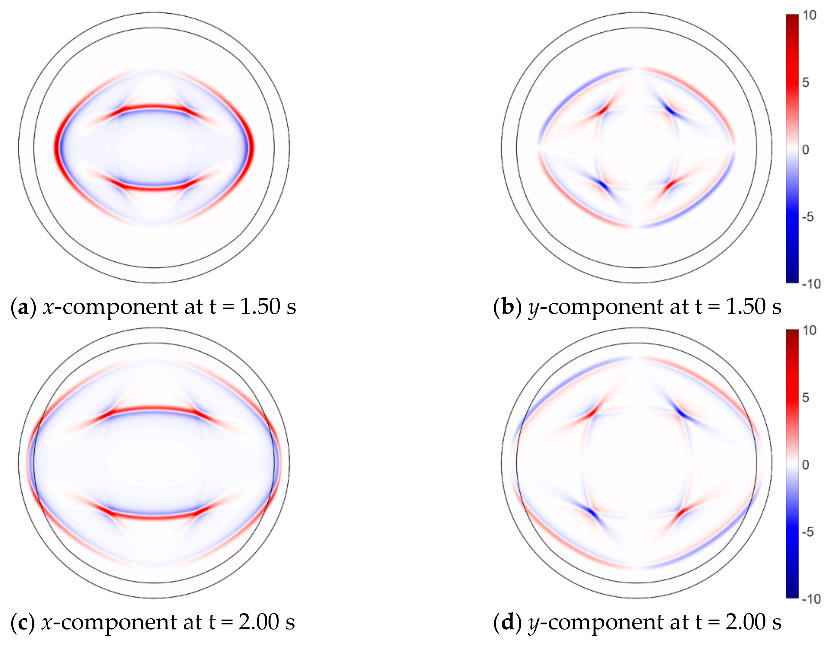
The elastic wave propagates to other blocks from block 5 at time t = 1.50 s (see Figure 6a,b), and the wave propagation is not affected by the continuous interface BCs. Then, the elastic wave is damped in MPML at 2.00 s, and the absorption of MPML is conditioned on the fact that the wavefield is not distorted by the reflecting wave (see Figure 6c,d).
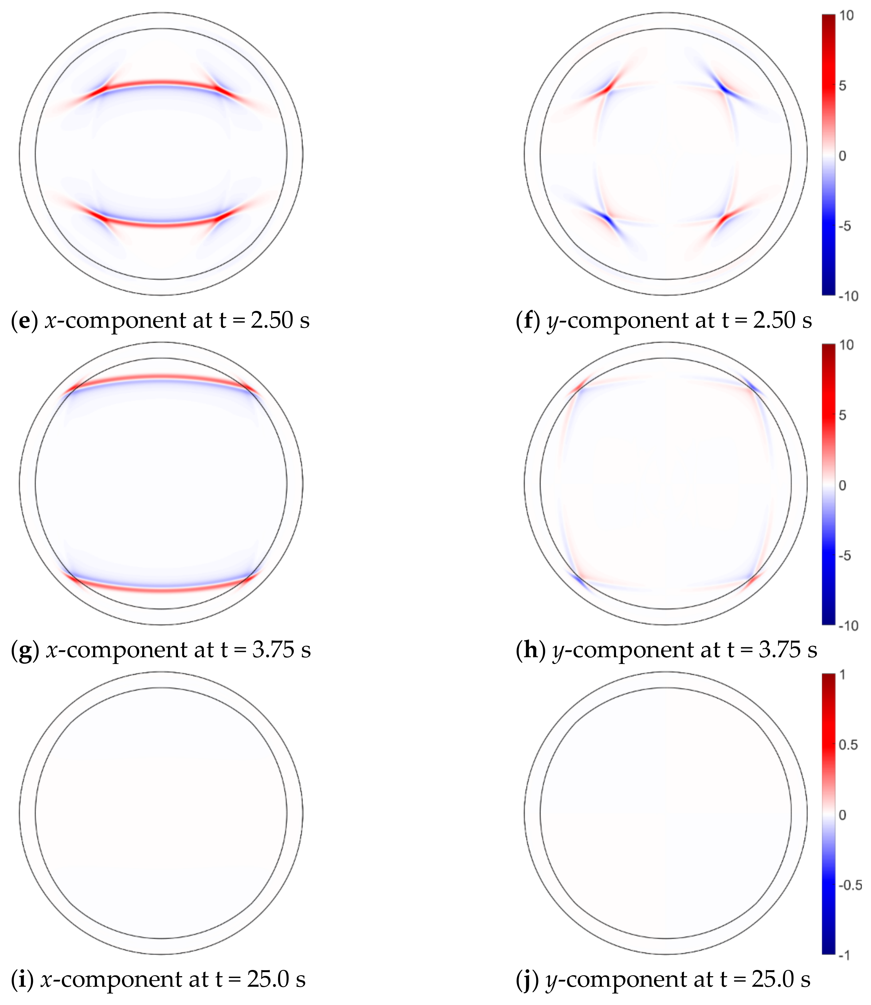
p-wave vanishes when the wave enters MPML at t = 2.50 s (see Figure 6e,f). Then, SV wave propagates to the MPML zone at t = 3.75 s (see Figure 6g,h). It can be seen that the amplitude of the elastic wave smoothly decreases to zero near the outermost boundary. For the long-time simulation, MPML ensures a stable solution (see Figure 6i,j). Despite the fact that the simulation is performed in an anisotropic medium and a circular domain, the framework of SMF of the elastic wave equations performs according to expectations. At the same time, the number of types and shapes of models that can be simulated has greatly increased owing to the multi-block method. In this simulation, PML without the damping ratio provides an unstable result, and the reason causing the unstable behavior of the PML solution is that the propagation of the elastic wave in the curve domain is similar to the propagation of elastic in an anisotropic medium. Besides, the anisotropic medium is used in this simulation. Generally, a larger damping ratio will be more favorable to ensure the stability of simulation; however, MPML is no longer “perfectly matched,” as the non-zero damping ratios are introduced, and the larger become the damping ratios, the stronger is the artificial reflections. A relatively small value of damping ratios in this numerical simulation can stabilize the solution, and it is deemed that that SMF of the elastic wave equation discretized by SBP-SAT requires a smaller damping ratio and consequently, behaves stable.
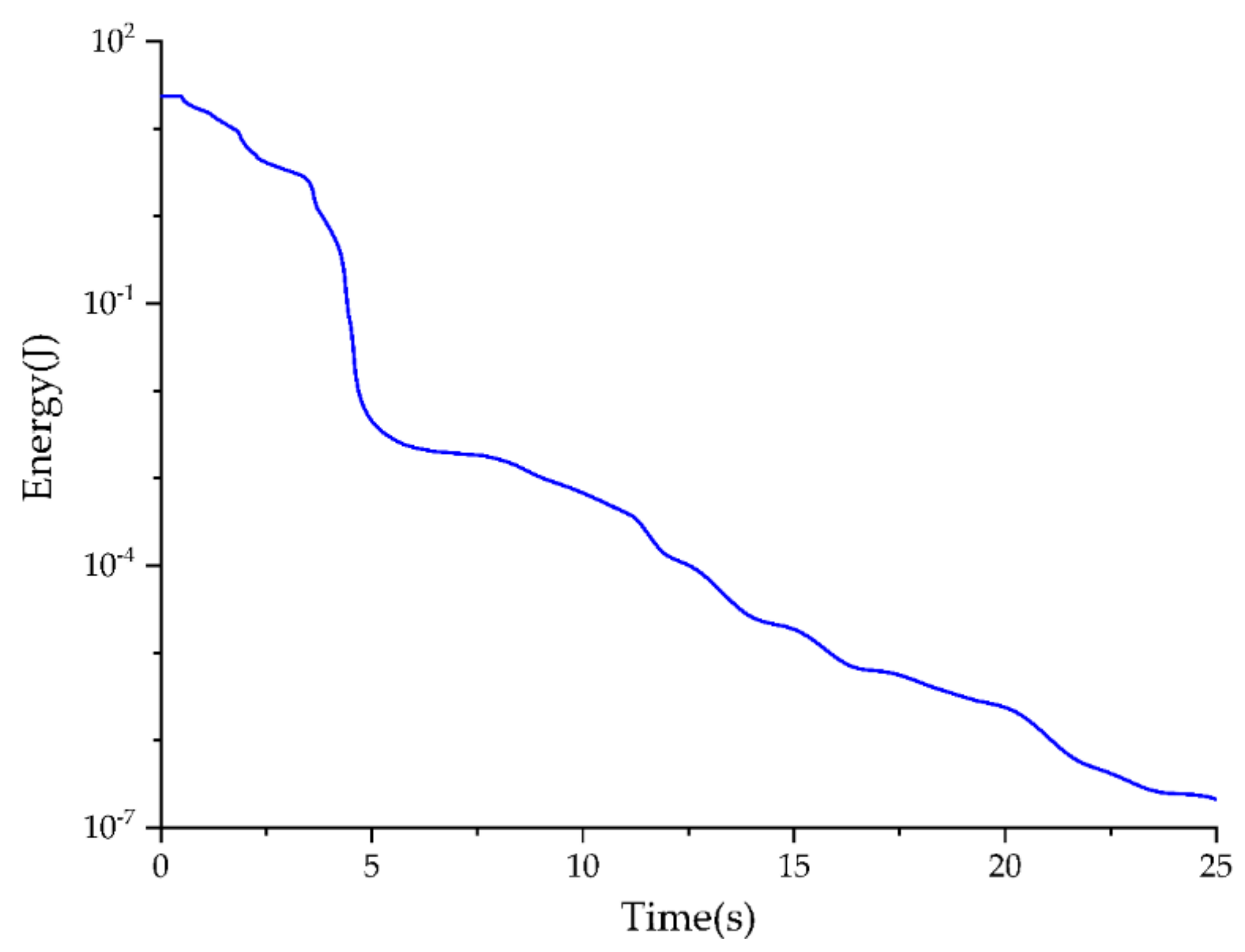
The total energy in the circular domain at different instants of time is shown in Figure 7. Here, the decay of energy and long-time stability of the framework of SMF combined with MPML are verified. The amplitude of the energy decays rapidly, while the direct wave passes out of the domain, so that the SMF framework can simulate the unbounded domain appropriately.

6.3. The 3D SMF Framework with Free-Surface Boundary Condition

To allow performing the 3D simulation, it is important to obtain a stable result in the curve domain, as well as seeking to have a smaller number of reflected waves generated at the boundaries surface. In this numerical simulation, a 3D SMF framework combined with MPML in the curve domain with undulating free-surface is tested. This scenario is consistent with the actual propagation of seismic waves. The MPML zone is utilized to better suppress the generation of the reflected wave comparing with non-PML. The parameters are listed in Table 3, and the curve physical domain is listed in Table A3.
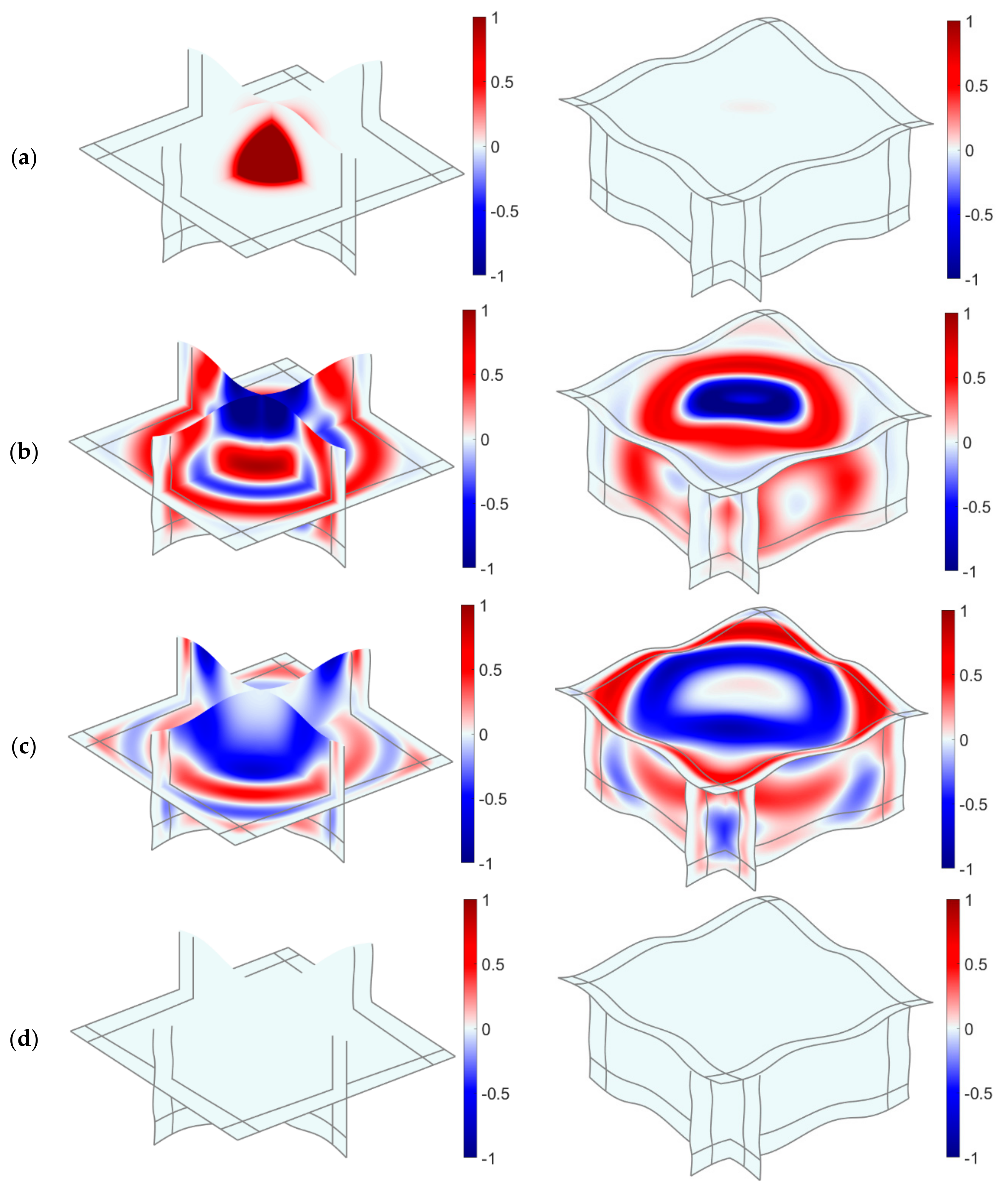
To visually represent the propagation of seismic waves in the 3D curve domain, a slice of the model is used to demonstrate the waveform of the seismic waves at different moments. Figure 8a shows the slice of the vz component in the reference simulation at time = 0 s. BC of the top is free-surface, so that the propagation path of the elastic wave will be changed. Moreover, the reflected wave propagates to the interior model, and the scattered waves will continue to move along the free-surface (see Figure 8b). Thereby, the behavior of MPML is illustrated, and the evolution of the elastic wavefield is demonstrated (see Figure 8c). Because of the existence of MPML, the body and surface waves are well-absorbed by the curve PML zone that matches the contour of the curve domain (see Figure 8d). Additionally, PML at the curve free-surface preserves the stability even if the elastic wave vanishes; therefore, the framework has not changed in terms of stability in this, which has its unique conveniences. Using other numerical methods, the implementation of the free-surface condition in PML when the absorbing layer reaches the free-surface has to change the algebraic form that satisfied BCs [52].
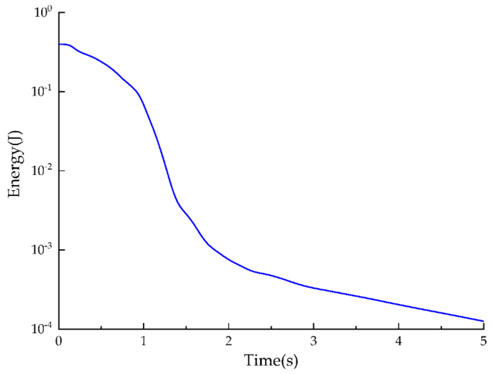
The energy in the 3D curve domain at different instants of time is shown in Figure 9. In this numerical experiment, the adoption of PML is in line with the stability requirements in terms of it is flexibility to use the SMF framework for the elastic wave equation combined with PML/ MPML/non-PML. Because of the existence of a free boundary, the energy decay rate in the three-dimensional curve domain is lower than that in the full-space model. However, the free boundary poses challenge the stability of the system to a greater extent. The proposed framework can realize the transformation of multiple boundary conditions with less modification required (BCs) and obtain stable numerical simulation results. It is shown that the establishment of a generic simulation process can greatly reduce the workload and complexity of formula compilation. Therefore, the proposed framework is intended to realize the synchronization of the wave absorption effect and stability simulation.

7. Conclusions

The key purpose of conducting the present research work was to develop an SMF framework for the elastic wave equation combined with MPML and to discretize this framework using the accurate high-order SBP-SAT methodology in the curve domain. This generic form, SMF, encapsulates various formulations of the elastic wave equation. In this case, SH and P-SV wave equations can be cast in an identical form only in the case when the parameter matrices are different. For the 3D elastic wave equation, SMF also has a form to similar the case of 2D. In turn, ADE CFS-MPML is extended to the curve domain to better suppress the reflected wave generated by the elastic wave propagated to the truncated boundary. SMF of the elastic wave equation facilitates the formulation derivation, and the implementation of program compilation becomes more convenient. Moreover, the generalization of SMF, implying that the wave equations are handled in the matrix form to avoid the full expansion of equations and introduction of the tangent/normal vectors. Thereafter, a numerical approximation using the SBP-SAT methodology combined with ADE CFS-MPML is proposed in such a way to allow the proposed framework being conveniently switched between PML/MPM/non-PML, so that a suitable case can be chosen to enable stability and absorption. Energy analysis is conducted considering both continuous and discretization cases. Several numerical examples are presented to demonstrate the properties of the resulting numerical method. It can be seen that discretization of the SMF framework combined with MPML results in high robustness, even though the curve domain causes anisotropic effects in the wave propagation behavior. The superiority of the proposed framework is confirmed by the observations that it allows simulating a more complex shape of the model and that the reflected wave can be suppressed by using MPML.
In the future research work, we will aim to perform an extension of the current model using a more efficient BC and also without deteriorating stability of the model. Moreover, another interesting research direction will be to set a more reasonable damping ratio for different models and parameters. Numerical simulation indicates that the proposed method has many application prospects. It can be challenging to model, discretize, and simulate an actual elevation and geological structure, and therefore, strict requirements are required to ensure the stability of such a method.

Author Contributions

Conceptualization, C.S.; Funding acquisition, Z.Y.; Methodology, C.S.; Project administration, Z.Y.; Supervision, Z.Y.; Writing—original draft, C.S.; Writing—review and editing, G.J. All authors have read and agreed to the published version of the manuscript.

Funding

The project was supported by the National Natural Science Foundation of China (Grant No. 11872156), National Key Research and Development Program of China (Grant No. 2017YFC1500801).

Acknowledgments

The authors are thankful to the program for Innovative Research Team in China Earthquake Administration.

Conflicts of Interest

The authors declare no conflict of interest.

Abbreviations

The following abbreviations are used in this manuscript:
SMFSymmetric Matrix Form
SBPSummation-by-Parts
SATSimultaneous Approximation Terms
CFSComplex Frequency Shifted
PMLPerfectly Matched Layer
MPMLMulti-axis Perfectly Matched Layer
ADEAuxiliary Differential Equation
PDEPartial Differential Equation
FDMFinite Difference Method
HOFDMHigh-Order Finite Difference Method
ABCAbsorbing Boundary Condition
BCBoundary Condition

Appendix A

Table A1. Contour of the curve physical domain.
Sidex(ξ, η)y(ξ, η)
West 6 × sin ( 7 π η ) 100 × η
East 100 + 5 × sin ( 9 π η ) 100 × η
South 100 × ξ 2 × sin ( 10 π ξ )
North 100 × ξ 100 + 2 × sin ( 10 π ξ )
Table A2. Contour of the curve physical domain.
Sidex(ξ, η)y(ξ, η)
W(1), E(2) 50 50 + 100 η
E(1), W(3) 50 50 + 100 η
S(1), N(4) 50 + 100 ξ 50
N(1), S(5) 50 + 100 ξ 50
S(2), W(4) 100 2 ξ 1 50 ξ 100 2 ξ 1 50 ξ
N(3), E(5) 50 + 100 2 50 ξ 50 + 100 2 50 ξ
N(2) 100 2 ξ 1 50 ξ 100 2 1 ξ 50 ξ
W(5) 50 100 2 50 η 50 100 2 50 η
S(3) 50 + 100 2 50 ξ 50 100 2 50 ξ
E(4) 100 2 100 2 50 η 100 2 + 100 2 50 η
W(2) 200 cos 5 4 π η 2 π 200 sin 5 4 π η 2 π
E(3) 200 cos 7 4 π + η 2 π 200 sin 7 4 π + η 2 π
S(4) 200 cos 5 4 π ξ 2 π 200 sin 5 4 π ξ 2 π
N(5) 200 cos 3 4 π ξ 2 π 200 sin 3 4 π ξ 2 π
Table A3. Contour of the curve physical domain.
Sidex(ξ, η, ζ)y(ξ, η, ζ)z(ξ, η, ζ)
BW 0 100 η + 2 sin ( 4 π η ) 2 sin ( 4 π η )
BE100 100 η 2 sin ( 4 π η ) 2 sin ( 4 π η )
BS 100 ξ + 2 sin ( 4 π ξ ) 0 2 sin ( 4 π ξ )
BN 100 ξ 2 sin ( 4 π ξ ) 100 2 sin ( 4 π ξ )
TW0 100 η + 2 sin ( 4 π η ) 50 2 sin ( 4 π η )
TE100 100 η 2 sin ( 4 π η ) 50 2 sin ( 4 π η )
TS 100 ξ + 2 sin ( 4 π ξ ) 0 50 2 sin ( 4 π ξ )
TN 100 ξ 2 sin ( 4 π ξ ) 100 50 2 sin ( 4 π ξ )
SW 2 sin ( 4 π ζ ) 100 η + 2 sin ( 4 π ζ ) 50 ζ
NW 2 sin ( 4 π ζ ) 100 η 2 sin ( 4 π ζ ) 50 ζ
SE 100 ξ 2 sin ( 4 π ζ ) 2 sin ( 4 π ζ ) 50 ζ
NE 100 ξ 2 sin ( 4 π ζ ) 2 sin ( 4 π ζ ) 50 ζ

References

  1. Alterman, Z.; Karal, F. Propagation of elastic waves in layered media by finite difference methods. Bull. Seismol. Soc. Am. 1968, 58, 367–398. [Google Scholar]
  2. Alford, R.M.; Kelly, K.R.; Boore, D.M. Accuracy of Finite-Difference Modeling of the Acoustic Wave Equation. Geophysics 1974, 39, 834–842. [Google Scholar] [CrossRef]
  3. Kelly, K.R.; Ward, R.W.; Treitel, S.; Alford, R.M. Synthetic Seismograms: A Finite-Difference Approach. Geophysics 1976, 41, 2–27. [Google Scholar] [CrossRef]
  4. Smith, W.D. The Application of Finite Element Analysis to Body Wave Propagation Problems. Geophys. J. R. Astron. Soc. 1975, 42, 747–768. [Google Scholar] [CrossRef] [Green Version]
  5. Marfurt, K.J. Accuracy of finite-difference and finite-element modeling of the scalar and elastic wave equations. Geophysics 1984, 49, 533–549. [Google Scholar] [CrossRef]
  6. Komatitsch, D.; Tromp, J. Introduction to the spectral element method for three-dimensional seismic wave propagation. Geophys. J. Int. 1999, 139, 806–822. [Google Scholar] [CrossRef]
  7. Kim, J.; Papageorgiou, A.S. Discrete Wave-Number Boundary-Element Method for 3-D Scattering Problems. J. Eng. Mech. 1993, 119, 603–624. [Google Scholar] [CrossRef]
  8. Papageorgiou, A.S.; Pei, D. A Discrete Wavenumber Boundary Element Method for study of the 3-D response 2-D scatterers. Earthq. Engng. Struct. Dyn. 1998, 27, 619–638. [Google Scholar] [CrossRef]
  9. Dumbser, M.; Käser, M. An arbitrary high-order discontinuous Galerkin method for elastic waves on unstructured meshes—II. The three-dimensional isotropic case. Geophys. J. Int. 2006, 167, 319–336. [Google Scholar] [CrossRef]
  10. Madariaga, R. Dynamics of an expanding circular fault. Bull. Seism. Soc. Am. 1976, 66, 639–666. [Google Scholar]
  11. Carpenter, M.H.; Gottlieb, D.; Abarbanel, S. Time-stable boundary conditions for finite-difference schemes solving hyperbolic systems: Methodology and application to high-order compact schemes. J. Comput. Phys. 1994, 111, 220–236. [Google Scholar] [CrossRef] [Green Version]
  12. Gustafsson, B. High Order Difference Methods for Time Dependent PDE; Springer: New York, NY, USA, 2008. [Google Scholar]
  13. Kreiss, H.O.; Scherer, G. Finite Element and Finite Difference Methods for Hyperbolic Partial Differential Equations. In Mathematical Aspects of Finite Elements in Partial Differential Equations; Elsevier: Amsterdam, The Netherlands, 1974; pp. 195–212. ISBN 9780122083501. [Google Scholar]
  14. Strand, B. Summation by parts for finite difference approximations for d/dx. J. Comput. Phys. 1994, 110, 47–67. [Google Scholar] [CrossRef]
  15. Albin, N.; Klarmann, J. An Algorithmic Exploration of the Existence of High-Order Summation by Parts Operators with Diagonal Norm. J. Sci. Comput. 2016, 69, 633–650. [Google Scholar] [CrossRef] [Green Version]
  16. Mattsson, K.; Almquist, M.; Van der Weide, E. Boundary optimized diagonal-norm SBP operators. J. Comput. Phys. 2018, 374, 1261–1266. [Google Scholar] [CrossRef]
  17. Mattsson, K. Summation by parts operators for finite difference approximations of second-derivatives with variable coefficients. J. Sci. Comput. 2012, 51, 650–682. [Google Scholar] [CrossRef]
  18. Carpenter, M.H.; Nordström, J.; Gottlieb, D. Revisiting and extending interface penalties for multi-domain summation-by-parts operators. J. Sci. Comput. 2010, 45, 118–150. [Google Scholar] [CrossRef] [Green Version]
  19. Olsson, P. Supplement to Summation by Parts, Projections, and Stability. I. Math. Comput. 1995, 64, S23–S26. [Google Scholar] [CrossRef]
  20. Olsson, P. Summation by parts, projections, and stability. II. Math. Comput. 1995, 64, 1473–1493. [Google Scholar] [CrossRef]
  21. Mattsson, K.; Olsson, P. An improved projection method. J. Comput. Phys. 2018, 372, 349–372. [Google Scholar] [CrossRef]
  22. Mattsson, K. Boundary Procedures for Summation-by-Parts Operators. J. Sci. Comput. 2003, 18, 133–153. [Google Scholar] [CrossRef]
  23. Svärd, M.; Carpenter, M.H.; Nordström, J. A stable high-order finite difference scheme for the compressible Navier–Stokes equations, far-field boundary conditions. J. Comput. Phys. 2007, 225, 1020–1038. [Google Scholar] [CrossRef]
  24. Svärd, M.; Nordström, J. A stable high-order finite difference scheme for the compressible Navier-Stokes equations. No-slip wall boundary conditions. J. Comput. Phys. 2008, 227, 4805–4824. [Google Scholar] [CrossRef]
  25. Del Rey Fernández, D.C.; Hicken, J.E.; Zingg, D.W. Review of summation-by-parts operators with simultaneous approximation terms for the numerical solution of partial differential equations. Comput. Fluids 2014, 95, 171–196. [Google Scholar] [CrossRef] [Green Version]
  26. Svärd, M.; Nordström, J. Review of summation-by-parts schemes for initial–boundary-value problems. J. Comput. Phys. 2014, 268, 17–38. [Google Scholar] [CrossRef] [Green Version]
  27. Gustafsson, B.; Kreiss, O.H.; Oliger, J. Time Dependent Problems and Difference Methods; Wiley: Hoboken, NJ, USA, 1995. [Google Scholar]
  28. Dovgilovich, L.; Sofronov, I. High-accuracy finite-difference schemes for solving elastodynamic problems in curvilinear coordinates within multiblock approach. Appl. Numer. Math. 2015, 93, 176–194. [Google Scholar] [CrossRef] [Green Version]
  29. Mattsson, K. Diagonal-norm upwind SBP operators. J. Comput. Phys. 2017, 335, 283–310. [Google Scholar] [CrossRef]
  30. Mattsson, K.; O’Reilly, O. Compatible diagonal-norm staggered and upwind SBP operators. J. Comput. Phys. 2018, 352, 52–75. [Google Scholar] [CrossRef]
  31. Hicken, J.E.; Zingg, D.W. Summation-by-parts operators and high-order quadrature. J. Comput. Appl. Math. 2013, 237, 111–125. [Google Scholar] [CrossRef] [Green Version]
  32. Del Rey Fernández, D.C.; Boom, P.D.; Zingg, D.W. A generalized framework for nodal first derivative summation-by-parts operators. J. Comput. Phys. 2014, 266, 214–239. [Google Scholar] [CrossRef]
  33. Ranocha, H. Generalised summation-by-parts operators and variable coefficients. J. Comput. Phys. 2018, 362, 20–48. [Google Scholar] [CrossRef] [Green Version]
  34. Hicken, J.E.; Del Rey Fernández, D.C.; Zingg, D.W. Multidimensional Summation-by-Parts Operators: General Theory and Application to Simplex Elements. SIAM J. Sci. Comput. 2016, 38, A1935–A1958. [Google Scholar] [CrossRef]
  35. Del Rey Fernández, D.C.; Hicken, J.E.; Zingg, D.W. Simultaneous Approximation Terms for Multi-dimensional Summation-by-Parts Operators. J. Sci. Comput. 2018, 75, 83–110. [Google Scholar] [CrossRef] [Green Version]
  36. Duru, K.; Virta, K. Stable and high order accurate difference methods for the elastic wave equation in discontinuous media. J. Comput. Phys. 2014, 279, 37–62. [Google Scholar] [CrossRef]
  37. Nissen, A.; Kormann, K.; Grandin, M.; Virta, K. Stable Difference Methods for Block-Oriented Adaptive Grids. J. Sci. Comput. 2015, 65, 486–511. [Google Scholar] [CrossRef] [Green Version]
  38. Cerjan, C.; Kosloff, D.; Kosloff, R.; Reshef, M. A nonreflecting boundary condition for discrete acoustic and elastic wave equations. Geophysics 1985, 50, 705–708. [Google Scholar] [CrossRef]
  39. Shin, C. Sponge boundary condition for frequency-domain modeling. Geophysics 1995, 60, 1870–1874. [Google Scholar] [CrossRef] [Green Version]
  40. Tago, J.; Métivier, L.; Virieux, J. SMART layers: A simple and robust alternative to PML approaches for elastodynamics. Geophys. J. Int. 2014, 199, 700–706. [Google Scholar] [CrossRef] [Green Version]
  41. Higdon, R.L. Absorbing Boundary Conditions for Difference Approximations to the Multi-Dimensional Wave Equation. Math. Comput. 1986, 47, 437–459. [Google Scholar] [CrossRef]
  42. Lee, J.H.; Kim, J.K.; Tassoulas, J.L. Application of a second-order paraxial boundary condition to problems of dynamics of circular foundations on a porous layered half-space. Soil Dyn. Earthq. Eng. 2011, 31, 291–305. [Google Scholar] [CrossRef]
  43. Guddati, M.N.; Lim, K.-W. Continued fraction absorbing boundary conditions for convex polygonal domains. Int. J. Numer. Meth. Eng. 2006, 66, 949–977. [Google Scholar] [CrossRef]
  44. Liao, Z.P.; Wong, H.L.; Yang, B.P.; Yuan, Y.F. A Transmitting Boundary for Transient Wave Analysis. Sci. Sin. Ser. A 1984, 27, 1063–1076. [Google Scholar]
  45. Liao, Z.-P. Extrapolation non-reflecting boundary conditions. Wave Motion 1996, 24, 117–138. [Google Scholar] [CrossRef]
  46. Lysmer, J.; Kuhlemeyer, R.L. Finite Dynamic Model for Infinite Media. J. Eng. Mech. ASCE 1969, 95, 859–877. [Google Scholar]
  47. Kouroussis, G.; Verlinden, O.; Conti, C. Finite-Dynamic Model for Infinite Media: Corrected Solution of Viscous Boundary Efficiency. Geophysics 2011, 137, 509–511. [Google Scholar] [CrossRef]
  48. Deeks, A.; Randolph, M. Axisymmetric Time-Domain Transmitting Boundaries. J. Eng. Mech. ASCE 1994, 120, 25–42. [Google Scholar] [CrossRef]
  49. Peng, C.; Toksöz, M.N. An optimal absorbing boundary condition for elastic wave modeling. Geophysics 1995, 60, 296–301. [Google Scholar] [CrossRef]
  50. Bérenger, J.P. A perfectly matched layer for the absorption of electromagnetic waves. J. Comput. Phys. 1994, 114, 185–200. [Google Scholar] [CrossRef]
  51. Appelö, D.; Kreiss, G. A new absorbing layer for elastic waves. J. Comput. Phys. 2006, 215, 642–660. [Google Scholar] [CrossRef]
  52. Zhang, Z.; Zhang, W.; Chen, X. Complex frequency-shifted multi-axial perfectly matched layer for elastic wave modelling on curvilinear grids. Geophys. J. R. Astron. Soc. 2014, 198, 140–153. [Google Scholar] [CrossRef] [Green Version]
  53. Kim, D. A Modified PML Acoustic Wave Equation. Symmetry 2019, 11, 177. [Google Scholar] [CrossRef] [Green Version]
  54. Givoli, D.; Neta, B. High-order non-reflecting boundary scheme for time-dependent waves. J. Comput. Phys. 2003, 186, 24–46. [Google Scholar] [CrossRef]
  55. Baffet, D.; Bielak, J.; Givoli, D.; Hagstrom, T.; Rabinovich, D. Long-time stable high-order absorbing boundary conditions for elastodynamics. Comput. Methods Appl. Mech. Eng. 2012, 241–244, 20–37. [Google Scholar] [CrossRef]
  56. Mattesi, V.; Darbas, M.; Geuzaine, C. A high-order absorbing boundary condition for 2D time-harmonic elastodynamic scattering problems. Comput. Math. Appl. 2019, 77, 1703–1721. [Google Scholar] [CrossRef]
  57. Kozdon, J.E.; Dunham, E.M.; Nordström, J. Interaction of waves with frictional interfaces using summation-by-parts difference operators: Weak enforcement of nonlinear boundary conditions. J. Sci. Comput. 2012, 50, 341–367. [Google Scholar] [CrossRef] [Green Version]
  58. Kozdon, J.E.; Dunham, E.M.; Nordström, J. Simulation of dynamic earthquake ruptures in complex geometries using high-order finite difference methods. J. Sci. Comput. 2013, 55, 92–124. [Google Scholar] [CrossRef] [Green Version]
  59. Duru, K.; Dunham, E.M. Dynamic earthquake rupture simulations on nonplanar faults embedded in 3D geometrically complex, heterogeneous elastic solids. J. Comput. Phys. 2016, 305, 185–207. [Google Scholar] [CrossRef]
  60. Rydin, Y.; Mattsson, K.; Werpers, J. High-fidelity Sound Propagation in a Varying 3D Atmosphere. J. Sci. Comput. 2018, 77, 1278–1302. [Google Scholar] [CrossRef] [Green Version]
  61. Duru, K.; Kreiss, G. Numerical interaction of boundary waves with perfectly matched layers in two space dimensional elastic waveguides. Wave Motion 2014, 51, 445–465. [Google Scholar] [CrossRef]
  62. Duru, K. A perfectly matched layer for the time-dependent wave equation in heterogeneous and layered media. J. Comput. Phys. 2014, 257, 757–781. [Google Scholar] [CrossRef]
  63. Duru, K.; Kozdon, J.E.; Kreiss, G. Boundary conditions and stability of a perfectly matched layer for the elastic wave equation in first order form. J. Comput. Phys. 2015, 303, 372–395. [Google Scholar] [CrossRef] [Green Version]
  64. Duru, K.; Gabriel, A.-A.; Kreiss, G. On energy stable discontinuous Galerkin spectral element approximations of the perfectly matched layer for the wave equation. Comput. Methods Appl. Mech. Eng. 2019, 350, 898–937. [Google Scholar] [CrossRef]
  65. Bécache, E.; Fauqueux, S.; Joly, P. Stability of perfectly matched layers, group velocities and anisotropic waves. J. Comput. Phys. 2003, 188, 399–433. [Google Scholar] [CrossRef] [Green Version]
  66. Meza-Fajardo, K.C.; Papageorgiou, A.S. A Nonconvolutional, Split-Field, Perfectly Matched Layer for Wave Propagation in Isotropic and Anisotropic Elastic Media: Stability Analysis. Bull. Seismol. Soc. Am. 2008, 98, 1811–1836. [Google Scholar] [CrossRef]
  67. Meza-Fajardo, K.C.; Papageorgiou, A.S. On the stability of a non-convolutional perfectly matched layer for isotropic elastic media. Soil Dyn. Earthq. Eng. 2010, 30, 68–81. [Google Scholar] [CrossRef]
  68. Meza-Fajardo, K.C.; Papageorgiou, A.S. Study of the Accuracy of the Multiaxial Perfectly Matched Layer for the Elastic-Wave Equation. Bull. Seismol. Soc. Am. 2012, 102, 2458–2467. [Google Scholar] [CrossRef]
  69. Ping, P.; Zhang, Y.; Xu, Y. A multiaxial perfectly matched layer (M-PML) for the long-time simulation of elastic wave propagation in the second-order equations. J. Appl. Geophys. 2014, 101, 124–135. [Google Scholar] [CrossRef]
  70. Zhao, Z.; Chen, J. Complex frequency-shifted multi-axial perfectly matched layer for frequency-domain seismic wavefield simulation in anisotropic media. Geophys. Prospect. 2019, 67, 1329–1344. [Google Scholar] [CrossRef]
  71. Eriksson, S.; Nordström, J. Exact Non-reflecting Boundary Conditions Revisited: Well-Posedness and Stability. Found. Comput. Math. 2017, 17, 957–986. [Google Scholar] [CrossRef] [Green Version]
Figure 1. Coordinate transformation.
Symmetry 12 00202 g001
Figure 2. Snapshots of propagation of the velocity magnitude (m/s) in the curve domain correspond to the SMF framework of MPML/PML/non-PML. For (a) time = 0.40 s; (b) time = 0.50 s; (c) time = 0.60 s; (d) time = 1.25 s; (e) time = 2.50 s.
Symmetry 12 00202 g002aSymmetry 12 00202 g002b
Figure 3. Energy decay in the curve domain using the framework of MPML/PML.
Symmetry 12 00202 g003
Figure 4. A comparison of the wavefield at node (101, 151).
Symmetry 12 00202 g004
Figure 5. Model of the decomposition of the circular domain into a multiblock.
Symmetry 12 00202 g005
Figure 6. Snapshots of propagation of the velocity magnitude (m/s) in the curve domain.
Symmetry 12 00202 g006aSymmetry 12 00202 g006b
Figure 7. Energy decay in the curve domain of multi-block.
Symmetry 12 00202 g007
Figure 8. Snapshots of propagation of the velocity magnitude (m/s) in the curve domain. For (a) time = 0 s; (b) time = 0.50 s; (c) time = 0.75 s; (d) time = 5.00 s.
Symmetry 12 00202 g008
Figure 9. Energy decay in the 3Dcurve domain using the framework of PML.
Symmetry 12 00202 g009
Table 1. Properties and discretization parameters for simulation.
ParametersValue
Curve physical domain properties
ρ2 kg/m3
G20 MPa
vs100 m/s
Discretization parameters
Initial condition 10 × exp x x c 2 + y y c 2 50
Number of grids in the x-direction201
Number of grids in the y-direction201
Time step0.0005 s
Total duration20 s
PML include grids interval-number20
α2
β02
tol10−4
Damping ratios0.05
Table 2. Properties and discretization parameters for simulation.
ParametersValue
Curve physical domain properties
ρ1000 kg/m3
c119.00 MPa
c225.94 Mpa
c331.60 MPa
c122.25 MPa
Discretization parameters
Initial condition 100 × exp x x c 2 + y y c 2 15
Number of grids in the x-direction201
Number of grids in the y-direction201
Time step0.0005 s
Total duration25 s
PML include grids interval-number30
α5
β05
tol10−8
Damping ratios0.05
Table 3. Properties and discretization parameters for simulation.
ParametersValue
Curve physical domain properties
ρ2 kg/m3
vp100 m/s
vs70 m/s
Discretization parameters
Initial condition 10 exp x x c 2 + y y c 2 + z z c 2 100
Number of grids in the x-direction121
Number of grids in the y-direction121
Number of grids in the z-direction61
Time step0.0005 s
Total duration5 s
PML include grids interval-number10
α5
β05
tol10−4
Damping ratios0.02