Abstract
The rotorcraft blade tip vortex rolled up by the blade tip when the rotor rotates at high speed will produce a complex induced velocity field, which will have an important impact on the aerodynamic load and performance of the rotor. For this reason, this paper carries out the research on the identification of blade tip vortex and the motion characteristics of the vortex. Through the time-resolved particle image velocimetry (TR-PIV) experiment, the flow field of the rotor at a fixed rotate speed (2100 r/min) with a collective pitch of 6° and 9° was obtained. Based on the vorticity field, Q criterion, and Ω criterion, the research on vortex identification and vortex motion characteristics are realized. The results show that with the increase of blade motion azimuth, the radial position of blade tip vortex gradually contracts inward and the axial position moves downward in hovering state. As the collective pitch of the rotor increases, the radial contraction becomes more obvious, and the axial displacement increases, at the same time, the blade tip vortex intensity increases. Comparative study results show that different vortex identification methods have obtained certain deviations in the vortex center. Compared with other vortex identification methods, the Ω criterion method has a smaller deviation and can accurately identify the vortex core radius and vortex boundary.
1. Introduction
The flow field structure around the rotor is more complicated than the fixed-wing, and its aerodynamic complexity is partly due to the unique aerodynamic environment around the rotor [1,2,3,4]. The rotor is subject to additional non-inertial forces due to rotation, such as Coriolis and centrifugal forces, the non-linear phenomena in the vortex evolution are more obvious, and the flow characteristics are also more abundant. The rotor blade velocity increases along the direction of the wingtip, and most of the aerodynamic force is generated at the wingtip. A strong blade tip vortex will appear in the wake of each blade tip, occupying a leading role in wake flow, and is the “skeleton” of the wake flow field. These vortices are always close to the rotor, generating a complex three-dimensional induced flow field, which affects the aerodynamic load of the rotor, aerodynamic performance, vibration level, aeroelasticity and acoustic performance [1,5,6,7].
Due to the complexity of the rotor wake, it is extremely important to analyze the vortex flow characteristics in the wake. In order to study the flow characteristics of the rotor wake, a lot of research has been carried out. The position of the vortex, the vortex core radius, and the vortex intensity have been studied, and there have been some notable results [1,8]. Landgrebe et al. first conducted experiments to measure the rotor hover trails [9,10]. Huang et al. obtained the vortex trajectory pattern of the blade tip by measuring the flow field around the blade tip and the wake area at different rotate speeds and the collective pitch in the hover state of the rotor [11,12]. However, how to accurately define and identify the blade tip vortex structure in the rotor wake flow field and analyze the interaction mechanism between the blade tip vortex based on this need further study.
In fact, the physical quantity that characterizes the rotational angular velocity of the fluid microelement is called vorticity, and the fluid area where the vorticity is highly concentrated is defined as a vortex, which is the vorticity is equal to two times the angular velocity [13]. However, this definition of vorticity cannot distinguish between real vortices and shearing regions. It shows that vortices cannot be measured by vorticity, and corresponding vorticity determination criteria must be used to accurately describe and analyze vortices [14,15,16,17,18,19,20].
Intuitively, vortex refers to the fluid that rotates within a flow. Although vortices can be observed in almost all real flows, mathematically, there is still no uniform and precise definition of a vortex, and the definition and identification of vortex are still difficult in aerodynamic research. Lugt defines a vortex as: “A vortex is the rotating motion of a multitude of material particles around a common center” [21]. However, this definition requires the definite position and orientation of the vortex core, which is difficult to apply to related research.
In order to extract the structure of vortices from a large amount of data from experiments and numerical simulations, several vortex identification methods have been proposed. Perry proposed that vorticity exists in the area where the eigenvalue of the velocity gradient tensor is complex, namely the method [22]. Hunt et al. proposed the well-known method, and believes that there is a vortex structure where the second invariant of the velocity gradient tensor is positive, and represents the balance between the shear strain rate and the magnitude of the vorticity [16,19,23]. Besides this, there are other vortex identification methods that are commonly used, such as λ2 for specific flow field data. The vortex structures can be well displayed by selecting appropriate vortex identification thresholds [13,16,17,23,24].
However, and are still some shortcomings in vortex identification. For example, they need to choose an appropriate threshold for each specific problem. Besides, the physical meaning of this criterion is not clear, and once the threshold is not selected properly, it will lead to the identification of non-physical phenomena. For example, when the absolute value of is selected to be too large, only the strong vortex will be captured and the weak vortex structure will be missed, resulting in the illusion that the vortex structure is broken.
In response to these problems, Liu et al. proposed a new vortex identification method that uses to estimate the degree of rigid body rotation of the fluid; that is, = 0 represents no rotation of the flow, and = 1 represents that the fluid does rigid body rotation. Choosing slightly greater than 0.5 (e.g., 0.51) as the boundary of the vortex structure avoids the uncertainty caused by the selection of the threshold [17,25]. The vortex identification method proposed by Liu solved uncertainty brought by the choice of the threshold value. However, although this vortex identification method was applied to the research of the rotor wake flow field, how to accurately define and identify the vortex structures and further analyze the interaction mechanism between vortex systems needs further verification and engineering.
For this purpose, this paper uses the time-resolved particle image velocimetry (TR-PIV) technology as a research tool for rotor flow field measurement and performs precise measurement experiments on the rotor blade tip vortex in hovering state. The vortex identification method is used to accurately capture and identify the blade tip vortex structure in the wake flow field in hovering state. The research methods and results of this paper can be used to analyze the generation, evolution, and interaction mechanism of vortices in rotor wakes, and provide a theoretical basis for wake vortex modeling and control.
2. Experimental Equipment and Research Methods
2.1. Experimental Model
The model of the helicopter body used in the experiment was a T-REX 450 L. During the experiment, the rotor was fixed on the mounting bracket (Figure 1), where the diameter of the bracket was 0.12 m, and the height of the bracket was 1.5 m, which could eliminate the ground effect to the rotor flow. The rotor had two blades, the blades were made of carbon fiber, the airfoil was NACA 0015, the blade length was 380 mm, the chord length was 32 mm (Figure 2), and the rotor solidity (the ratio of the blade area to the disk area) was 0.104.
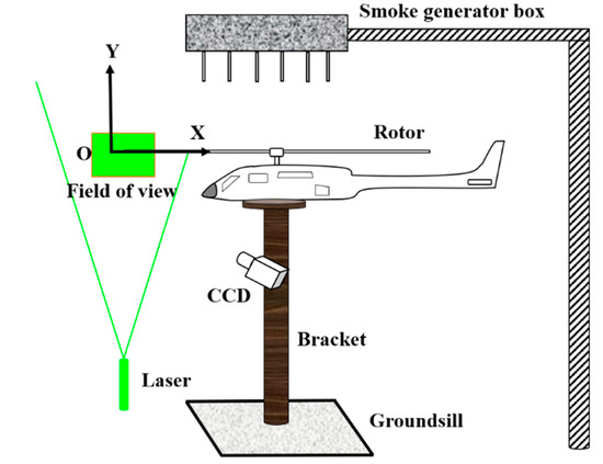
Figure 1.
Schematic diagram of the experimental setup.
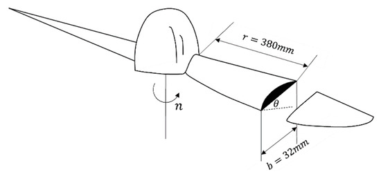
Figure 2.
Schematic diagram of the rotor blade.
When carrying out the PIV flow field test experiment, a smoke generator box was placed directly above the rotor, which can evenly eject the tracer particles downward. The laser’s optical path was from the bottom to the top, and the sheet light was perpendicular to the plane of the disk propeller. The thickness of the sheet light in the observation area was about 1 mm. The camera was placed horizontally and perpendicular to the laser plane. The rotation direction of the rotor was clockwise when viewed from top to bottom. There was no free flow during the experiment, which represents the helicopter rotor was on hovering state. In this research, the rotate speed of the blade was fixed at 2100 r/min, which corresponding to the blade tip speed was 83.57 m/s. Two rotor collective pitch angles (θ) were conducted (6° and 9°) for flow field measurement.
2.2. Experimental Equipment
The main principles of PIV are (Figure 3): record twice tracer particles position in a very short time (Δt = t1 − t2) through high-speed cameras. By image analysis technique, the particle displacement was obtained (namely, Δx and Δy). Through the particle displacement and exposure time interval (Δt), the velocity vector of each point in the flow field ΔV can be calculated by and . Other flow parameters can be calculated based on the velocity of particles (including vorticity diagram of the flow field, velocity component diagram, flow diagram, swirl diagram, etc.).
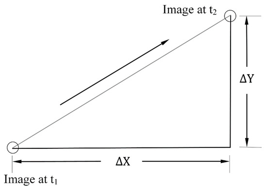
Figure 3.
Particle image velocimetry (PIV) velocity measurement principle.
The TR-PIV system used for flow field testing was mainly composed of a camera (PCO. dimax HS4, a dual-pulse laser, laser wavelength λ = 527 nm, maximum output energy e = 30 mJ, and divergence angle 5 mrad), synchronizer, and controller. During the experiment, the camera sampling frequency and laser emission frequency , the double exposure time interval Δt = 200 μs, the camera pixels were 2000 × 2000 pix, the exposure time was 100 μs, and the camera lens aperture was 5.9. The tracer particles were e-liquid (glycerin, ethylene glycol mixture) heated by the smoke machine to form steam particles with a particle diameter of about 0.6 μm. Black matte paint was sprayed on the surface of the blade model to eliminate the error caused by the reflection of intense laser on the surface before the experiment.
In post-processing, the PIV view2C software was used for cross-correlation analysis of the captured images, and correlation as determined using the standard FFT correlation algorithm, the Nyquist-frequency filtering, and the 9-point least-squares peak computing algorithm based on the Gauss fitting. The inquiry area had 64 × 64 pixels, the overlap factor was 50%, and the system error of the PIV was less than 4%.
2.3. Ω Vortex Identification Method
According to the tensor decomposition theorem, the velocity gradient tensor can be decomposed into a symmetrical part and an antisymmetric part. Mathematically, the symmetrical part of the velocity gradient tensor is the deformation of a fluid micelle, and the antisymmetric part is a vortex, that is:
The first term at the right end of the Formula (1) represents the deformation of the fluid, and the second term at the right end represents the rotation of the fluid. The expression of ‘A’ in the Formula (1) is:
The expression of ‘B’ in the rotation part in the Formula (1) is:
Based on this tensor decomposition, Liu et al. proposed an vortex identification method. Physically, represents the ratio of the antisymmetric part to the symmetric part. The expression for estimating is:
In order to avoid the problem of dividing by zero when actually performing vortex analysis of PIV or numerical simulation, a minimum value of a positive parameter is introduced. [17,25,26,27,28]. Then is:
According to the theory developed by Liu et al. and the verification cases based on DNS and LES calculation, the threshold of is generally taken as 0.51, = 0.001×(−)max [17,27]. Based on this, the vortex structures can accurately capture most of the conditions. This paper chooses the method to analyze the blade tip vortex characteristics in hovering state. Because this paper is a two-dimensional flow field study, the calculation expression of the vortex identification method becomes:
3. Results and Discussions
Through the PIV test, the flow field induced by rotor blade tip vortex under different experimental conditions were obtained. Section 3.1 introduces the typical flow structure of the blade tip vortex. Section 3.2 uses vorticity to analyze the unsteady motion characteristics of the blade tip vortex. Section 3.3 uses the criterion to study the characteristics of the blade tip vortex. In Section 3.4, the vortex identification method is introduced to study the motion characteristics of the blade tip vortex. In Section 3.5, comparative studies are conducted and different vortex identification methods are analyzed.
3.1. Blade Tip Vortex Flow Structure
When the rotor blade rotates at high speed, the boundary layer on the upper and lower surfaces of the airfoil separates from the trailing edge of the blade to form a very thin viscous layer, which is called the vortex sheet. Due to the combined effect of the pressure gradient in the wingspan and the wing chord direction, the airflow at the tip of the blade will roll up and pull out a very strong vortex, namely the blade tip vortex. Figure 4 shows the transient PIV flow field during the rotor hover (rotation speed of 2100 r/min, and a collective pitch of 6°. The background is the original image with tracer particles taken by PIV, and the colored arrows are the velocity vectors obtained after processing). The position and shape of the blade tip vortex can be clearly seen from the figure.
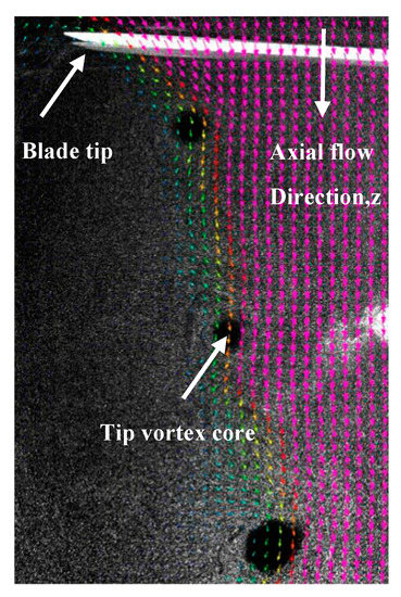
Figure 4.
Transient blade tip vortex flow structure (rotation speed of 2100 r/min, collective pitch of 6°).
The structure of the blade tip vortex at different vortex age angles is different. These vortices move down along the vertical axis and gradually move to the inner side of the paddle disk to form an obvious boundary of the wash flow. With the increase of the vortex age angle, the vortex core of blade tip vortex becomes larger. This is consistent with most conclusions [5].
When the rotor is at the hovering state, its aerodynamic characteristics can be considered as symmetrical and periodic changes. Therefore, the flow field characteristic of one blade rotating at a 180° azimuth angle can be used to represent the vortex field characteristic of the blade tip. Figure 5 shows the schematic diagram of six different azimuth angles selected in this paper.
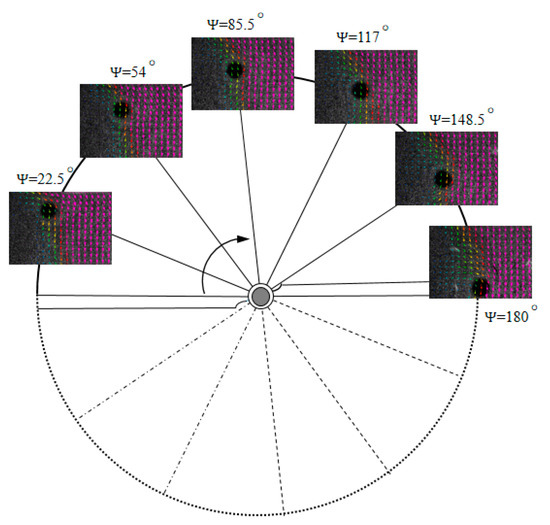
Figure 5.
Schematic diagram of different azimuth angles.
3.2. Vortex Motion Characteristics Based on Vorticity
In two-dimensional conditions, the vorticity formula is as follows:
where and ν represent the radial velocity (X-axis) and axial velocity (Y-axis) of the fluid in the observing window, respectively. Figure 6 and Figure 7 show the transient vorticity contours at the condition of the rotation speed of 2100 r/min, collective pitch of 6°, and rotation speed of 2100 r/min, collective pitch of 9°. Both experiments gave results for six different azimuth angles (22.5°, 54°, 85.5°, 117°, 148.5°, and 180°). The schematic diagram of the definition of azimuth angles is shown in Figure 5.
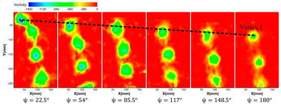
Figure 6.
Vorticity contours at different azimuth angles at the rotor rotation speed of 2100 r/min and the collective pitch of 6°.
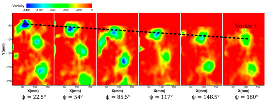
Figure 7.
Vorticity contours at different azimuth angles at the rotor rotation speed of 2100 r/min and the collective pitch of 9°.
It can be seen from Figure 6 that after the blade tip vortex is formed, with the increase of the azimuth angle, the vortices contract to the blade hub and move down axially. At the same time, the vorticity amplitude of the blade tip gradually decreases with the increase of azimuth angle, which reflects that the blade tip vortex dissipates continuously due to its viscosity during its motion. Comparing Figure 6 and Figure 7, it can be found that when the rotating speed is constant, at the same azimuth angle condition, the vorticity of the blade tip becomes larger with the increase of the collective pitch. It is shown that the blade tension increases with the increase of the collective pitch, and the tip induced vortex is stronger.
Figure 8 shows the dimensionless trajectory of the blade tip vortex (Vortex 1) generated by Blade 1 based on the vorticity criterion. It can be seen that at a certain rotate speed, as the collective pitch increases, the blade tension increases, the down washing speed of the blade tip vortex is increased, and the radial contraction is more serious. At the same time, the axial displacement is also faster.
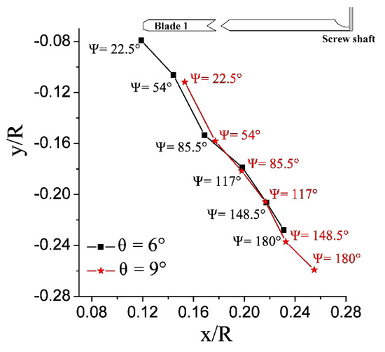
Figure 8.
Radial and axial trajectory of rotor blade tip vortex at different azimuth angles (based on vorticity criterion).
3.3. Vortex Motion Characteristics Based on Q Criterion
According to the criterion proposed by Hunt et al., the expression of the criterion is:
where A represents the strain rate tensor, B represents the rotation tensor, represents the relative size of the local rotation rate and the stretching rate, and vortices exist in the region of “ > 0”. Consistent with the definition in Section 2.3, the expressions of A and B are as follows:
The form of the criterion expression in a two-dimensional condition is:
Figure 9 and Figure 10 show the vortex distribution identified by criterion under different azimuth angles at the condition of the rotor rotation speed of 2100 r/min, collective pitch of 6°, and rotation speed of 2100 r/min, collective pitch of 9°.
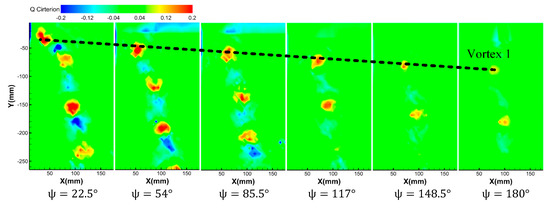
Figure 9.
Vortex distribution identified by the Q criterion at different azimuth angles at the rotor rotation speed of 2100 r/min and the collective pitch of 6°.
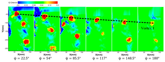
Figure 10.
Vortex distribution identified by the Q criterion at different azimuth angles at the rotor rotation speed of 2100 r/min and the collective pitch of 9°.
It can be seen from the results that under the criterion, the motion trajectory of the blade tip vortex is basically the same as the trajectory trend through the vorticity criterion. That is, after the blade tip vortex generates, the vortex radially contracts along with the axial downward movement. With the increase of azimuth, the vortex intensity decreases obviously. Different from Section 3.2, under the criterion, the value of alternates between positive and negative values at the same azimuth angle, which reflects that during the generation, evolution and movement of the blade tip vortex, rotation, and shear deformation exist simultaneously (vortex is positive value, shear deformation is negative value). In addition, with the increase of azimuth, both rotation and shear flow decrease and eventually dissipate.
Comparing Figure 9 and Figure 10, it can be found that at the same azimuth angle, when the rotating speed is constant, the vortex core has a larger radius and stronger vorticity with the increase of collective pitch. It is shown that the blade tension increases with the increase of the collective pitch, and the tip induced vortex is stronger.
According to the criterion, Figure 11 shows the radial and axial trajectory of the rotor blade tip vortex at different azimuth angles generated by Blade 1 under different operating conditions. It is consistent with the conclusion in Section 3.2. At a certain rotate speed, as the collective pitch increases, the radial contraction and the axial displacement are obvious.
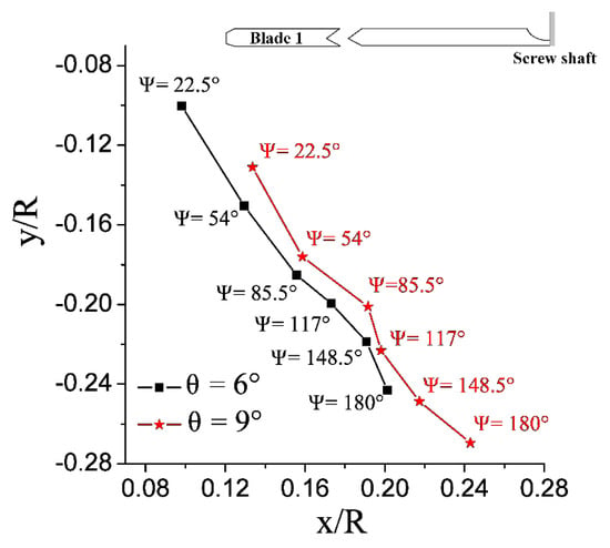
Figure 11.
Radial and axial trajectory of rotor blade tip vortex at different azimuth angles (based on the Q criterion).
3.4. Vortex Motion Characteristics Based on Ω Criterion
3.4.1. Ω Criterion Vortex Identification Results
Figure 12 and Figure 13 show the vortex distribution identified by the criterion under different azimuth angles at the condition of the rotor rotation speed of 2100 r/min, collective pitch of 6° and rotation speed of 2100 r/min, collective pitch of 9°. Take notice that Figure 12 and Figure 13 only show the antisymmetric part of the speed gradient tensor (namely, rotational part, which represents vortex) by the criterion.
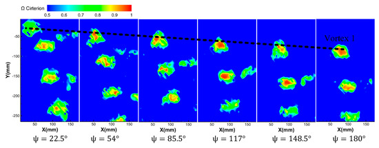
Figure 12.
Vortex distribution identified by the Ω criterion at different azimuth angles at a rotor rotation speed of 2100 r/min and the collective pitch of 6°.
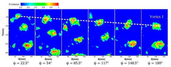
Figure 13.
Vortex distribution identified by Ω criterion at different azimuth angles at a rotor rotation speed of 2100 r/min and the collective pitch of 9°.
It can be seen that under the criterion, the blade tip vortex movement trend is close to the conclusion of the vorticity and the criterion; that is, as the azimuth angle increases, the blade tip vortex moves radially toward the hub and moves axially downward. At the same time, as the azimuth angle increases, the value of decreases, indicating that the blade tip vortex is dissipating.
Similarly, based on the criterion vortex identification method, Figure 14 shows the radial and axial vortex trajectory at different azimuth angles generated Blade 1 under different operating conditions. It also shows that at a certain rotate speed, as the collective pitch increases, the radial contraction of the blade tip vortex is more obvious, and at the same time, the axial displacement is also faster.
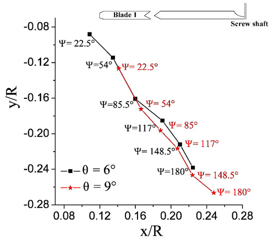
Figure 14.
Radial and axial trajectory of rotor blade tip vortex at different azimuth angles (based on the Ω criterion).
3.4.2. Vortex Boundary Identification
The boundary of the vortex is defined by the interface between the rotating area and the non-rotating area. Generally, the velocity gradient in the horizontal direction can be extracted from the vortex core center to obtain the vortex boundary size. In this paper, the vortex boundary is extracted based on the criterion (selecting threshold = 0.51).
Figure 15 and Figure 16 show the vortex boundary under different azimuth angles at the condition of the rotor rotation speed of 2100 r/min, collective pitch of 6°, and rotation speed of 2100 r/min, collective pitch of 9°. As can be seen from the figures, the vortex boundary gradually decreases with the increase of azimuth angle. By comparing Figure 15 and Figure 16, it can be found that when the collective pitch increases, the vortex boundary increases under the same azimuth angle.
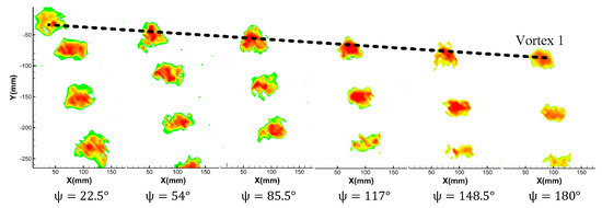
Figure 15.
Vortex boundary with a rotor rotation speed of 2100 r/min and the collective pitch of 6° (Ω = 0.51).
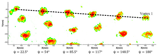
Figure 16.
Vortex boundary with a rotor rotation speed of 2100 r/min and the collective pitch of 9° (Ω = 0.51).
Figure 17 and Figure 18 show the vortex boundary and vortex core boundary identified by the criterion under different azimuth angles at the condition of the rotor rotation speed of 2100 r/min, collective pitch of 6° and rotation speed of 2100 r/min, collective pitch of 9°. (the vortex core boundary selection the threshold = 0.95).
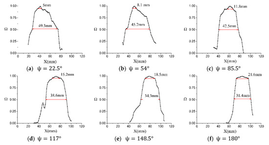
Figure 17.
Schematic diagram of vortex boundary and vortex core boundary at 2100 r/min and 6° collective pitch.
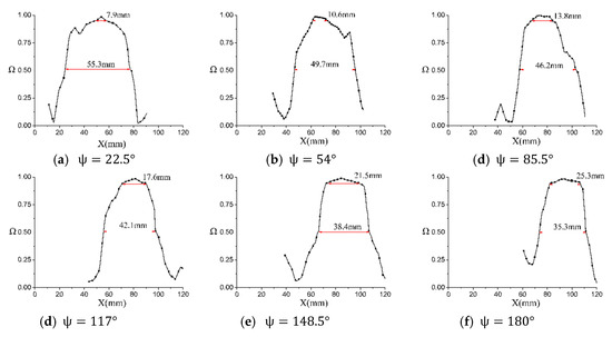
Figure 18.
Schematic diagram of vortex boundary and vortex core boundary at 2100 r/min and 9° collective pitch.
As can be seen from Figure 17, under the test conditions in this paper, with the increase of azimuth angle, the vortex core increases and the vortex boundary decreases gradually. The main reason is that after the vortex generates, during the process of radial and axial motion, the vortex energy is gradually dissipated due to the fluid viscosity, so the vortex boundary gradually decreases. The reason for the increase in the center of the vortex core is that the formation moment of the blade tip vortex is a strongly concentrated vortex. With the development and dissipation of the blade tip vortex, the vortex circulation quantity gradually decreases, resulting in a decrease in centrifugal force and a gradual increase in the radius of the vortex core, which is consistent with the results of the flow display in Figure 4.
At the same azimuth angle, when the collective pitch is increased, on account of the blade tip vortex induced by the large collective pitch is stronger, the quantitative value of the large collective pitch is larger than that of the small one, regardless of the vortex boundary or vortex core boundary.
3.5. Comparative Analysis of Blade Vortex Trajectory under Different Vortex Identification Criterion
Figure 19a,b, respectively, show a comparison of vortex trajectories by different vortex identification methods at the condition of rotating speed of 2100 r/min and collective pitches of 6° and 9°. In general, all three vortex identification methods obtain the same trend of the vortex trajectory, and the blade tip vortex is radial contraction and axial downward displacement. Moreover, when the collective pitch increases, the radial contraction distance is larger and the axial motion is faster. However, it can be seen that there is a big difference between the results of the vorticity criterion and the criterion. With the criterion method, the difference quantity is smaller.
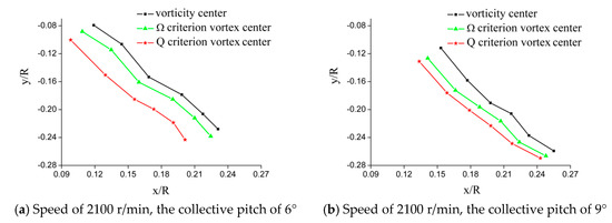
Figure 19.
Comparison of vortex trajectories by different vortex identification methods.
4. Conclusions
In this paper, through the TR-PIV flow field tests, the characteristics of the blade tip vortex under hovering state are studied, and the following conclusions are drawn:
- (1)
- When the rotor is at the hovering state, its aerodynamic characteristics can be considered as symmetrical and periodic changes;
- (2)
- At a certain rotate speed, as the collective pitch increases, the blade tension increases, the down washing speed of the blade tip vortex is increased, and the radial contraction is more serious. At the same time, the axial displacement is also faster;
- (3)
- With the increase of blade azimuth, blade tip vortex of the radial position moves to the hub and the axial location moves down gradually. At the same azimuth, with the collective pitch increases, blade tip vortex radial contraction is more obvious and axial displacement is larger;
- (4)
- In hovering state, as the blade tip vortex evolves, the vortex core radius gradually increases, and the vortex boundary gradually decreases. At a certain rotor rotate speed, as the collective pitch increases, the amplitude of the blade tip vorticity increases;
- (5)
- With different vortex identification methods, the obtained blade tip vortex center has a certain deviation. Compared with other methods, the Ω criterion can accurately distinguish vortices and shears, and can accurate quantitative the vortex core radius and vortex boundary.
In this paper, the motion characteristics of blade tip vortex under the hover state are obtained, and the research on vortex identification of blade tip vortex is carried out. The corresponding results can provide a basis for the study of the rotor complex flow field.
Author Contributions
Conceptualization, H.D.; Software, H.D. and W.K.; data curation, H.D., W.K., M.H., W.Z. and M.T.; writing-original draft preparation, W.K. and Y.W.; writing-review and editing, W.L.; Supervision, H.D.; project administration, H.D.; funding acquisition H.D. All authors have read and agreed to the published version of the manuscript.
Funding
This work was supported by National Natural Science Foundation of China (No. 51806181), the open fund from Rotor Aerodynamics Key Laboratory (No. RAL20180202-2), the open fund from National Key Laboratory of Science and Technology on Aero-Engine Aero-Thermodynamics (SKLA20180104), the financial support of the Sichuan Provincial Department of Education (No. 18ZA0458), the open fund from Key Laboratory of Aeroengine Pneumatic and Thermal Defence Science and Technology (No. 6142702180101), and “Young Scholars” Program of Xihua University. The Key scientific research fund of Xihua University (No. Z17111)).
Conflicts of Interest
The authors declare no conflict of interest.
References
- Ebrahimpour, M.; Shafaghat, R.; Alamian, R.; Safdari Shadloo, M. Numerical Investigation of the Savonius Vertical Axis Wind Turbine and Evaluation of the Effect of the Overlap Parameter in Both Horizontal and Vertical Directions on Its Performance. Symmetry 2019, 11, 821. [Google Scholar] [CrossRef]
- Muhsen, H.; Al-Kouz, W.; Khan, W. Small Wind Turbine Blade Design and Optimization. Symmetry 2020, 12, 18. [Google Scholar] [CrossRef]
- Wei, Z.; Yang, W.; Xiao, R. Pressure Fluctuation and Flow Characteristics in a Two-Stage Double-Suction Centrifugal Pump. Symmetry 2019, 11, 65. [Google Scholar] [CrossRef]
- Sarkar, M.; Julai, S.; Wen Tong, C.; Toha, S. Effectiveness of Nature-Inspired Algorithms using ANFIS for Blade Design Optimization and Wind Turbine Efficiency. Symmetry 2019, 11, 456. [Google Scholar] [CrossRef]
- Gardner, A.D.; Wolf, C.C.; Raffel, M. Review of measurement techniques for unsteady helicopter rotor flows. Prog. Aerosp. Sci. 2019, 111, 100566. [Google Scholar] [CrossRef]
- Bauknecht, A.; Merz, C.B.; Raffel, M.; Landolt, A.; Meier, A.H. Blade-Tip Vortex Detection in Maneuvering Flight Using the Background-Oriented Schlieren Technique. J. Aircr. 2014, 51, 2005–2014. [Google Scholar] [CrossRef]
- Mula, S.M.; Stephenson, J.H.; Tinney, C.E.; Sirohi, J. Dynamical characteristics of the tip vortex from a four-bladed rotor in hover. Exp. Fluids 2013, 54, 1600. [Google Scholar] [CrossRef]
- Gursul, I.; Wang, Z. Flow Control of Tip/Edge Vortices. AIAA J. 2018, 56, 1731–1749. [Google Scholar] [CrossRef]
- Romani, G.; Casalino, D. Rotorcraft blade-vortex interaction noise prediction using the Lattice-Boltzmann method. Aerosp. Sci. Technol. 2019, 88, 147–157. [Google Scholar] [CrossRef]
- Landgrebe, A.J. The Wake Geometry of a Hovering Helicopter Rotor and Its Influence on Rotor Performance. J. Am. Helicopter Soc. 1972, 7, 3–15. [Google Scholar] [CrossRef]
- Clark, D.R.; Landgrebe, A.J. Wake and boundary layer effects in helicopter rotor aerodynamics. In Proceedings of the 4th Fluid and Plasma Dynamics Conference, Palo Alto, CA, USA, 21–23 June 1971. [Google Scholar]
- Hassan, A.A.; Charles, B.D. Airfoil Design for Helicopter Rotor Blades—A Three-Dimensional Approach. J. Aircr. 2015, 34, 197–205. [Google Scholar] [CrossRef]
- Haller, G. An objective definition of a vortex. J. Fluid Mech. 2005, 525, 1–26. [Google Scholar] [CrossRef]
- Jeong, J.; Hussain, F. On the identification of a vortex. J. Fluid Mech. 1995, 285, 69–94. [Google Scholar] [CrossRef]
- Dong, X.; Wang, Y.; Chen, X.; Dong, Y.; Zhang, Y.; Liu, C. Determination of epsilon for Omega vortex identification method. J. Hydrodyn. 2018, 30, 541–548. [Google Scholar] [CrossRef]
- Da Silva, C.B.; Pereira, J.C.F. Invariants of the velocity-gradient, rate-of-strain, and rate-of-rotation tensors across the turbulent/nonturbulent interface in jets. Phys. Fluids 2008, 20, 55101. [Google Scholar] [CrossRef]
- Fu, W.; Li, C.; Lai, Y. Estimation of turbulent natural convection in horizontal parallel plates by the Q criterion. Int. Commun. Heat Mass Trans. Rapid Commun. J. 2013, 45, 41–46. [Google Scholar] [CrossRef]
- Hirschi, C.R. Characterization of visually detected coherent motions in the turbulent boundary layer. In Proceedings of the Fluies Engineering Division—2001, New Orleans, LA, USA, 29 May–1 June 2001; American Society of Mechanical Engineers: New York City, NY, USA, 1991; Volume 1, pp. 285–290. [Google Scholar]
- And, A.E.P.; Chong, M.S. A Description of Eddying Motions and Flow Patterns Using Critical-Point Concepts. Ann. Rev. Fluid Mech. 1987, 19, 125–155. [Google Scholar]
- Limacher, E.; Morton, C.; Wood, D. On the trajectory of leading-edge vortices under the influence of Coriolis acceleration. J. Fluid Mech. 2016, 800, R1. [Google Scholar] [CrossRef]
- Lugt, H.J.; Gollub, J.P. Vortex Flow in Nature and Technology. Am. J. Phys. 1985, 53, 381. [Google Scholar] [CrossRef]
- Lugt, J.H. Vortex flow and maximum principles. Am. J. Phys. 1985, 53, 649. [Google Scholar] [CrossRef]
- Gomes-Fernandes, R.; Ganapathisubramani, B.; Vassilicos, J.C. Evolution of the velocity-gradient tensor in a spatially developing turbulent flow. J. Fluid Mech. 2014, 756, 252–292. [Google Scholar] [CrossRef]
- Kim, J.; Moin, P.; Moser, R. Turbulence statistics in fully developed channel flow at low Reynolds number. J. Fluid Mech. 1987, 177, 133–166. [Google Scholar] [CrossRef]
- Liu, C.; Gao, Y.; Dong, X.; Wang, Y.; Liu, J.; Zhang, Y.; Cai, X.; Gui, N. Third generation of vortex identification methods: Omega and Liutex/Rortex based systems. J. Hydrodyn. 2019, 31, 205–223. [Google Scholar] [CrossRef]
- Zhang, Y.; Liu, K.; Xian, H.; Du, X. A review of methods for vortex identification in hydroturbines. Renew. Sust. Energy Rev. 2018, 81, 1269–1285. [Google Scholar] [CrossRef]
- Liu, C.; Wang, Y.; Yang, Y.; Duan, Z. New omega vortex identification method. Sci. China Phys. Mech. Astron. 2016, 59, 684711–684719. [Google Scholar] [CrossRef]
- Tian, S.; Gao, Y.; Dong, X.; Liu, C. Definitions of vortex vector and vortex. J. Fluid Mech. 2018, 849, 312–339. [Google Scholar] [CrossRef]
© 2020 by the authors. Licensee MDPI, Basel, Switzerland. This article is an open access article distributed under the terms and conditions of the Creative Commons Attribution (CC BY) license (http://creativecommons.org/licenses/by/4.0/).