1. Introduction
It is well known that in the last decades, remarkable changes have affected the field of civil engineering; the most relevant example of the previous statement can be referred to the conventional way of designing seismic-resistant structures. In fact, the common national and international codes [
1,
2] propose, as a traditional strategy, the possibility of conceiving structures to behave elastically in the case of occasional seismic events, while during severe earthquakes instead, sources able to dissipate the seismic input energy should be properly activated in well-defined structural components in order to prevent the collapse and protect human life. It is clear that the main drawback of such an approach relies on the fact that the abovementioned dissipating elements should undergo damage to fulfill their function. These damages become the main sources of indirect losses, which are becoming too heavy to be economically sustained for most developed countries.
For such a reason, many research efforts have been devoted to conceiving devices able to dissipate the seismic input energy preventing structural collapses, protecting human lives and also safeguarding the economic impacts and the full-operativity of structures after the occurrence of seismic events.
Particularly referring to reinforced concrete structures, the isolators [
3] are probably the most known devices in the mass culture, which are often exploited by designers since their adoption also enables engineers to simply design more so-called superstructures. Furthermore, such a technology can also be applied in the case of seismic retrofitting, which is currently a very popular topic [
4,
5].
Nevertheless, other solutions, based on the use of steel elements, such as steel bracings [
6,
7], have been conceived; even though they are much more susceptible to stability issues and corrosion [
8], they are able to provide a high performance because of the high ductility and good mechanical properties of cross-sections that they offer [
9,
10]. These steel devices can also be used for the seismic retrofitting of reinforced concrete or masonry structures [
11,
12].
Beyond these solutions, many efforts have dealt with the study of dissipative elements endowed in steel seismic-resistant Moment Resisting Frames (MRFs). In fact, the most common way of designing steel structures able to withstand severe seismic events is by dissipating the seismic input energy thanks to the plastic engagement of beam ends [
13,
14]. This considered, full-strength joints have to be properly designed, applying the beam-column hierarchy-criteria, in order to prevent damages in the connections and the columns.
Nevertheless, the seismic events of Kobe (1995) [
15] and Northridge (1994) [
16] highlighted some limits of the traditional design rules, since many beam-to-column connections belonging to several perimetral American MRFs and in-space Japanese MRFs underwent brittle fracture. The causes of such unexpected and undesired behavior were ascribed to the welding techniques used at the time, which proved to provide very low ductility [
17]. In order to overcome such a trouble, an approach called Reduced Beam Section (RBS), or dog-bone, consisting of weakening the beam ends into areas located sufficiently far from the column [
17,
18], was proposed. This improves the structural seismic performance, concentrating the damage in specific regions thanks to both the lower stress concentrations in welds [
19] and the higher local ductility.
In the last decades, however, an alternative design approach, aimed at using partial-strength beam-to-column joints, has been investigated. The main advantage of partial strength joints consists in increasing the local ductility and energy dissipation capacity, provided that capacity design principles are applied in designing the single components [
20,
21]. This means that the weakest joint component has to be preliminarily defined and designed in order to provide the needed ductility and energy dissipation supply. All the remaining joint components, including the beam and column ends, instead have to be designed in such a way not to be engaged in the plastic range. The consequence is that these elements are designed adopting over-strength factors to account for the strain hardening and the variability in the mechanical material properties exhibited by the weakest joint component. Many works have dealt with partial-strength joints considering different weak components: the web panel of bolted end-plate connections [
22,
23]; the end-plate of bolted end-plate connections [
24,
25,
26,
27]; and the T-stubs of T-stub joints [
28,
29].
Another good example of such a strategy is represented by the possibility of including friction dampers in steel connections [
30] obtaining two benefits: easy replaceability and high dissipation capacity [
31]. In particular, the high dissipation capacity is guaranteed by the wide and stable hysteretic cycles, which allow to concentrate damage in devices that only undergo minor yielding.
The first conceived friction device is known as Sliding Hinge Joint (SHJ); nevertheless, many studies have been devoted to investigating different structural details [
32,
33,
34,
35,
36]. According to this approach, the beam bottom flange is equipped with a friction damper which allows to fix the flexural strength of the joint through the tightening torque of pre-loadable high strength bolts and to control the ductility thanks to the length of the slotted holes. The other two relevant advantages consist of the possibility of uncoupling the stiffness and the resistance of the connection to the very negligible post-elastic strain-hardening, thanks to the high initial stiffness friction dampers have, and to the yield plateau after the slippage force has been attained. A good example of such a solution is represented by a friction connection, which has been widely studied at Salerno University [
37,
38].
In most of the previous studies concerning the partial-strength beam-to-column joints, the methodological approach consists of properly designing the connections and afterward testing some sub-assemblies thanks to monotonic and/or cyclic tests [
39,
40,
41]. In many cases, these experimental campaigns have been validated against numerical outcomes carried out employing Finite Element (FE) software, and also the influence of the connections on the global structural behavior has been defined throughout numerical simulations [
42,
43,
44]. Instead, very few efforts have been devoted to experimentally define how these connections are able to affect the structural response of seismically loaded MRFs.
For such a reason at the STRENGTH (STRuctural ENGineering Test Hall) Laboratory of the University of Salerno, an experimental activity has been planned, which consists of assessing the behavior of five different traditional and innovative beam-to-column connections when belonging to a real-scale one-bay two-storey steel structure submitted to a sequence of earthquake events applied using the pseudo-dynamic method. The selected connection typologies, designed to provide a rotation capacity higher than the minimum required by EC8 [
1] for Ductility Class High (DCH), are: RBS; Extended-End-Plate (EEP) joints; Double-Split-Tee (DST) joints; Double-Split-Tee X-shaped (DST-X) joints; and friction joints.
The first experimental campaign concerning the structure equipped with RBS connections has already been performed, and the experimental results have been discussed in [
45]. The second experimental campaign, referred to the structure endowed with friction joints, has not yet been performed. Nevertheless, this paper deals with the discussion and the comparison of the experimental and numerical results of the first campaign, and the numerical simulations referred to the structure equipped with the friction connections.
The main aim of the present paper is to propose a blind analysis of the structure equipped with the friction joints and to assess which are the possible benefits in terms of global and local response that the proposed connection typology is able to provide. For such a reason, since the experimental campaign concerning the structure with RBSs is not the novelty of this work, the data of the first experimental campaign will be briefly discussed in the following paragraphs.
2. Design of Connections and Building Mock-Up
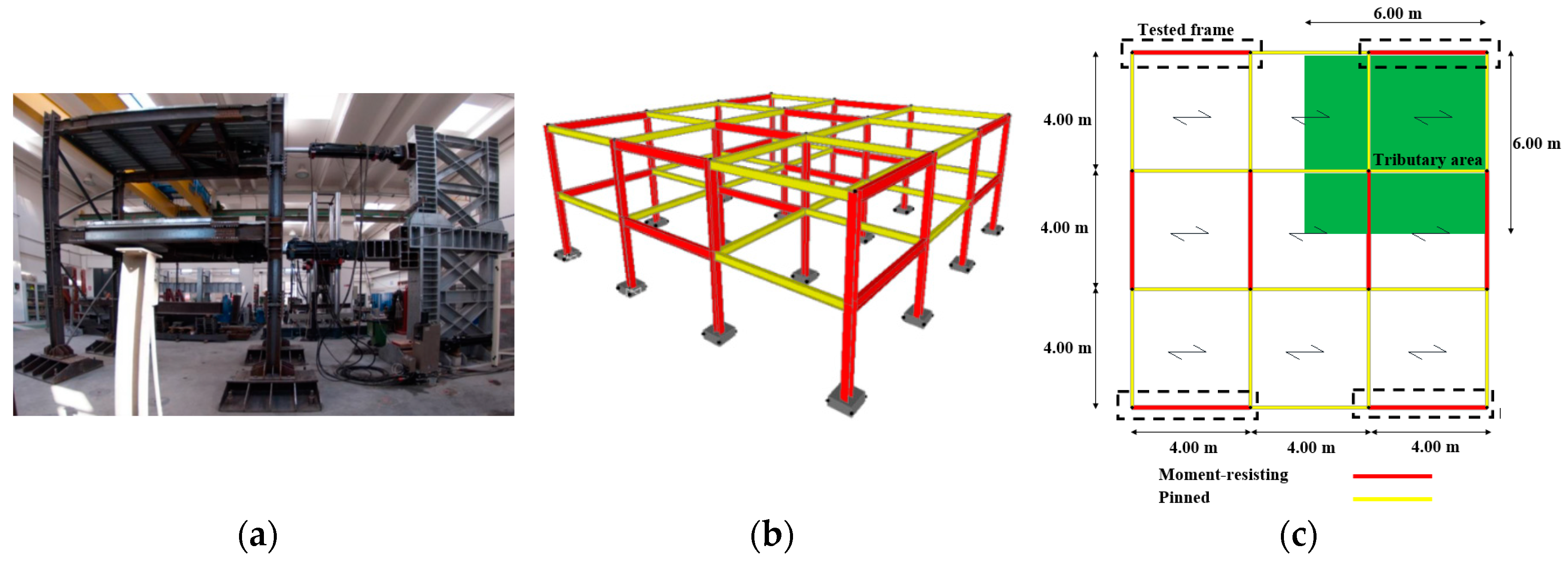
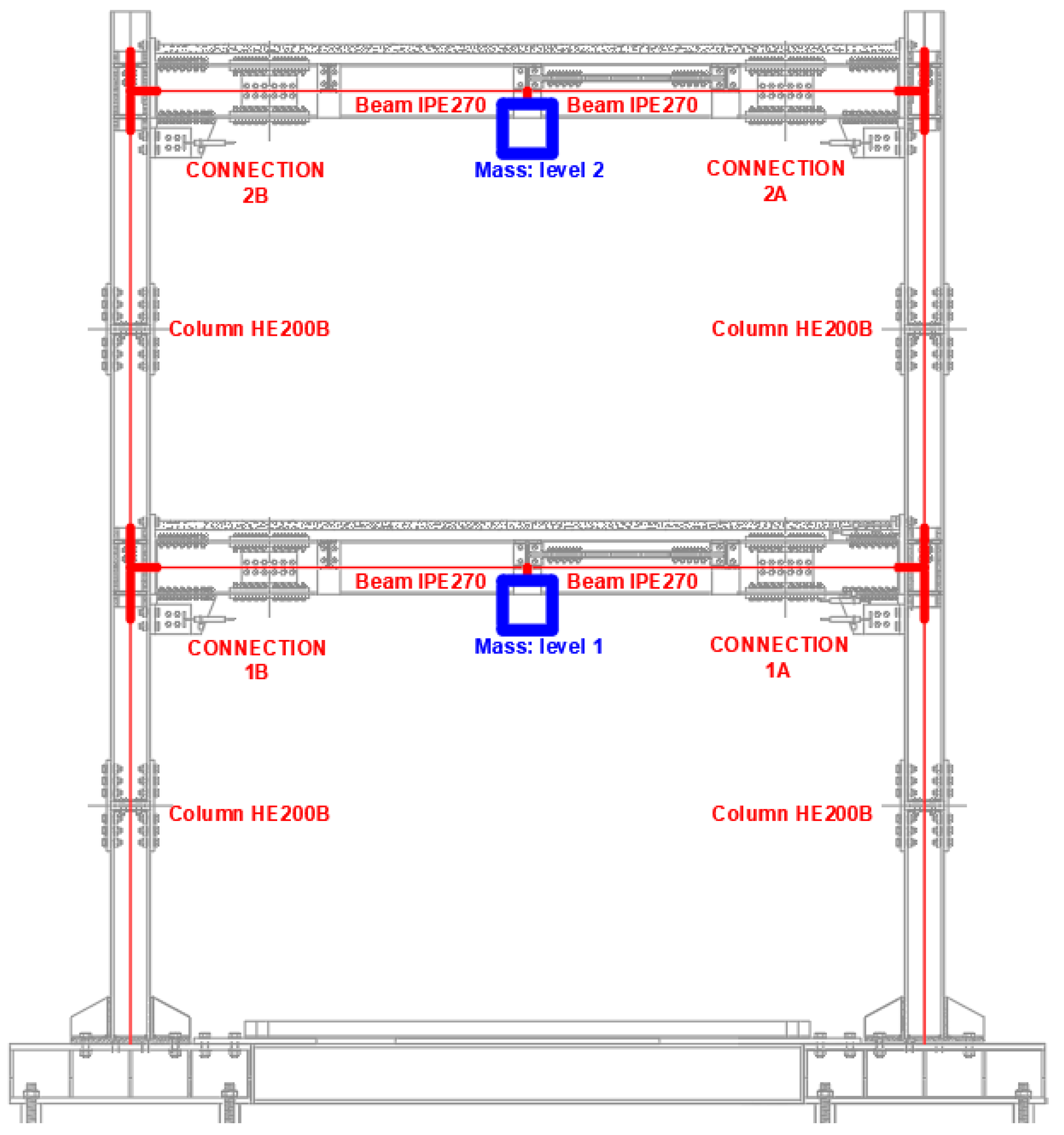
The tested steel structure is shown in
Figure 1a; it is characterized by one bay and two storeys. The seismic actions are withstood by two longitudinal MRFs, while two transversal bracings have been conceived in order to prevent undesired accidental torsion. The longitudinal bay span is equal to 4 m, the transversal span is 2 m and the interstorey height is equal to 2.40 m. The tested structural scheme is representative of a more complex reference structure characterized by three bays in each direction (
Figure 1b), whose lengths are equal to 4 m. All the bays are considered nominally pinned, except for those belonging to the MRFs (
Figure 1c).
In
Table 1, the loads and the masses applied to the structure are reported. The masses have been assessed considering that the tributary area of each MRF corresponds to 1/4 of the total floor area, with an increase of about 10% in order to account for the weight of structural members and claddings. The building, conceived to be classified in DCH with a behavior factor equal to 6, has been designed according to Eurocode 8 [
1] type-1 spectrum, a peak ground acceleration (PGA) equal to 0.35 g, and a type-B soil. The structural members have been designed to comply with Eurocode 8 provisions [
2], considering both the serviceability and ultimate limit states requirements. In particular, assuming that the partition walls of the buildings do not interfere with the deformation of the main structure, the design interstorey drifts under service conditions have been limited to 1%. Considering the previous limitations, IPE 270 beams made of S275JR steel grade and HEB 200 columns made of S355JR steel grade have been selected.
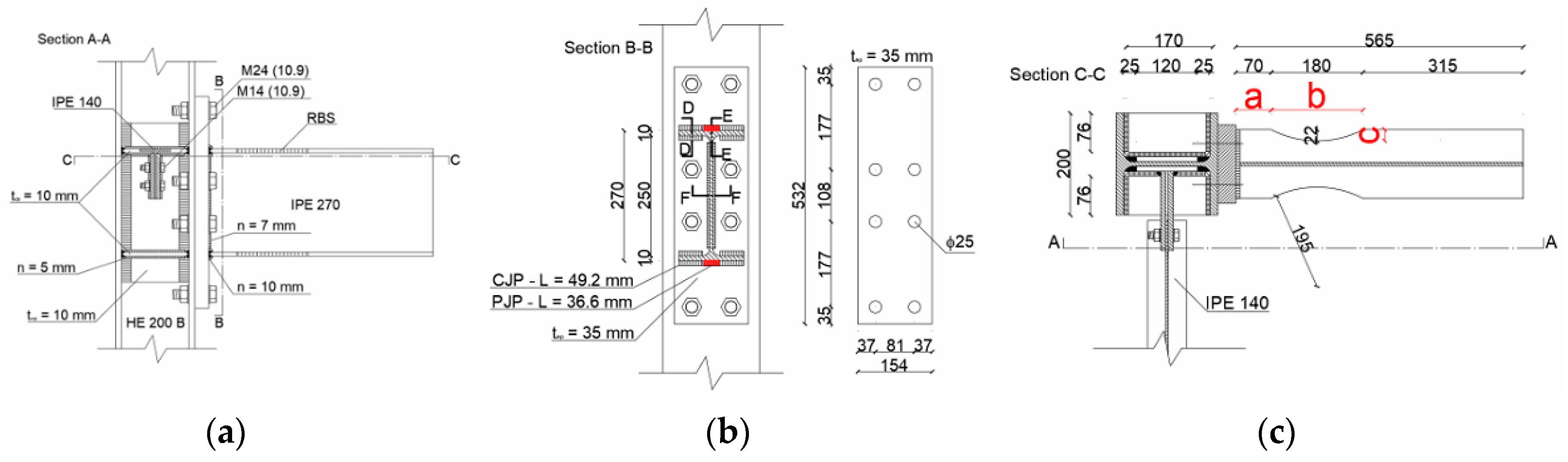
During the first experimental campaign, the building mock-up has been equipped with RBS connections. RBSs have been connected to the columns through EEP connections, while they have been connected to the beams using splice connections (consisting in bolted cover plates), the aim of which is to allow an easy substitution of the connections after the testing activity.
As aforementioned, the dissipative strategy of RBS connections is based on the possibility of confining the plastic engagement at beam ends by weakening them in such a way to shift the dissipative zone far from the welds. RBS connections have been studied since the 90s [
18,
46], and their design is ruled under EC8 part 1.3 and AISC 358-16 [
2,
19].
Referring to the analyzed case, RBSs have been designed limiting the flange width reduction to 25%, according to FEMA 351 [
17], and starting from the knowledge of the bending moment (
) and the shear force (
) acting at the RBSs centrelines when the plastic hinges are fully developed. According to the previous limit, a flange reduction equal to 22 mm has been defined (
Figure 2), while
and
have been assessed according to Equations (1) and (2)
where
is the plastic modulus of the RBS,
is the overstrength factor,
is the measured value of the yield strength of the RBS obtained from preliminary coupon tests (it is equal to 345 MPa),
is the beam net length,
is the end-plate thickness, and
and
are geometrical parameters which control the length and position of the RBS, defined according to [
18] (
Figure 2).
Taking into account the stepping up of the bending moment due to the distance between the RBS centreline and the column flange, it is possible to assess the moment that the connection has to withstand according to Equation (3):
It is important to highlight that the bending moment acting at the column flange is lower than the beam plastic resistance (
). Starting from the knowledge of the previously defined actions, all the other elements of the connections have been properly designed according to the component method [
20,
21] (
Figure 2).
Instead, the recently studied friction connections [
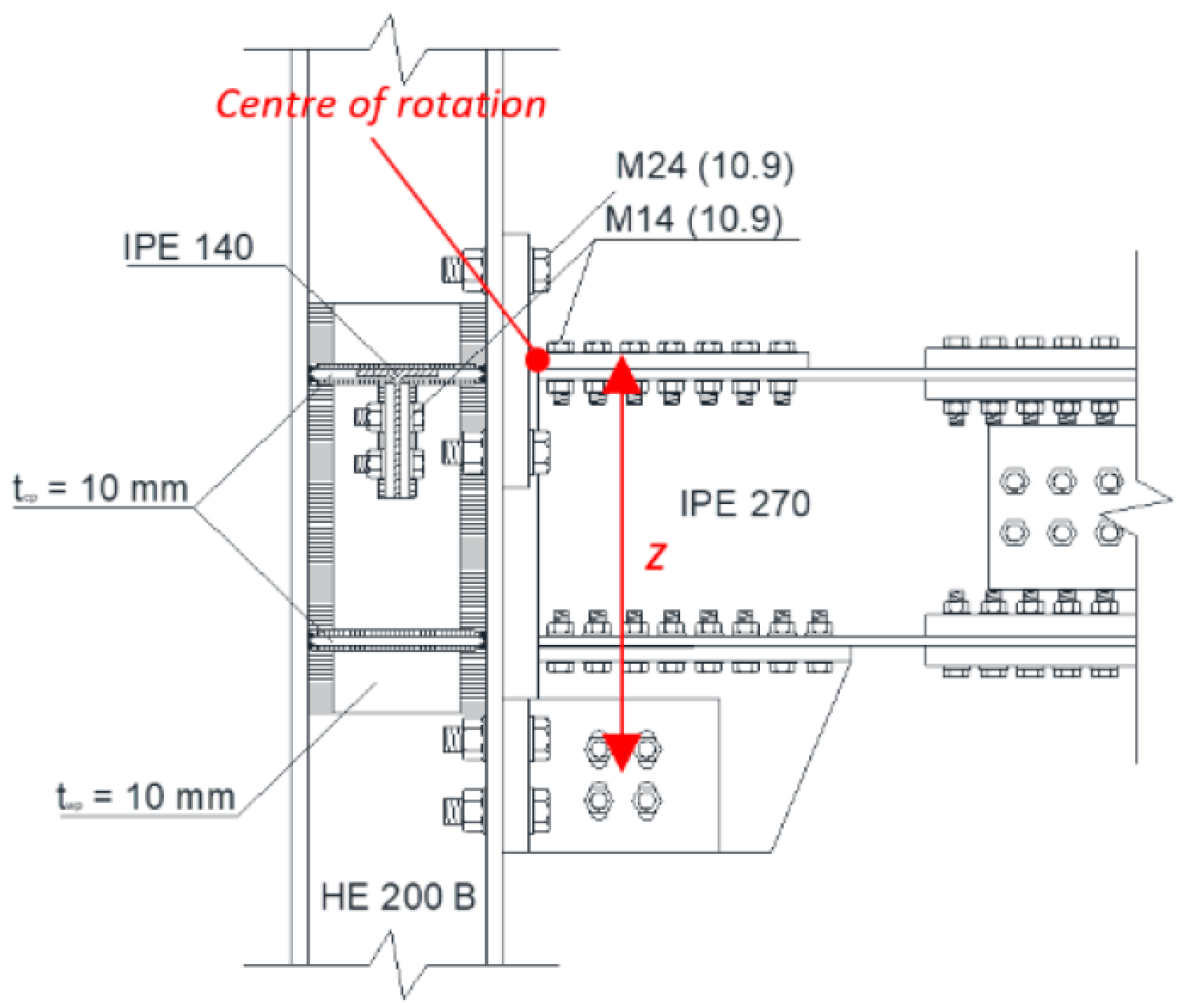
36] have been conceived in such a way to withstand high deformations in plastic range without any damage. These connections are characterized by friction dampers located at the beam end bottom flange and connected with two L-stubs and a haunch to the column and the beam, respectively (
Figure 3). The top flange of the beam is instead connected to the column flange thanks to a bolted T-stub. The friction pads are characterized by steel plates coated with a thermally sprayed thin layer of aluminum, which are able to provide a dynamic friction coefficient equal to 0.53.
The dissipative friction connections have been conceived in order to exhibit, at column flange, the same flexural strength designed for RBSs. According to the first capacity design principle, the friction damper is the first element which has to be defined; its design sliding force is limited to 60% of the maximum force that the beam in bending is able to withstand according to Equation (4)
where
is the plastic bending moment of the beam (it is equal to 171.82 kNm) and
is the vertical distance between the T-stub and the centre of the haunch (it is equal to 440 mm). This obviously means that the friction devices slide when bending moments achieve the value of
.
After the design of the dissipative elements (the friction pads), according to the second capacity design principle, all the non-dissipative components are conceived in order to remain in the elastic range when dissipative parts attain their ultimate resistance. It is important to check that the bending moment at the column flange is lower than the flexural resistance of the beams. This check can be assessed according to Equation (5)
where
is the bending acting at column face (it is equal to 183.5 kNm),
is the shear length of the beam (equal to 2.12 m) and
is the length of the haunch, equal to 245 mm. The ratio
is equal to 0.94, which is very close to the same ratio assessed for the case of RBS connections.
4. First Experimental Campaign: Structure Equipped with RBS Connections
The first experimental campaign concerning the structure with RBS connections has already been performed, and the main experimental results are discussed in [
45]. The tests consisted of simulating the dynamic behavior of the mock-up through the pseudo-dynamic method applying a set of five accelerograms, selected among those reported in
Table 2. Some technical issues obliged to repeat two tests. In fact, the first test was interrupted because the unexpected slides of column bases footings occurred, while during the third test the maximum load capacity of one of the actuators was reached. The slide of the footings was solved by connecting relatively the column bases and the rigid reaction wall, while the third was repeated adopting a lower scale factor. The sequence of imposed earthquakes is described in
Table 3. The conclusion of the campaign was achieved by the occurrence of the unexpected failure of two RBS connections at the first floor of the structure.
Furthermore, a 3D numerical model of the structure (
Figure 4a) was carried out thanks to the software SeismoStruct [
48], modelling the structural members with inelastic force-based elements and concentrating the expected active plastic sources at the beam ends. In particular, the hysteretic behavior of the connections has been defined thanks to the smooth link element located at the centerline of the reduced section of the applied connection typology. Instead, all the other elements belonging to the joint have been modelled as rigid components for what concerns the parts in the nodal panel, and elastic components for the remaining ones, as depicted in (
Figure 4b).
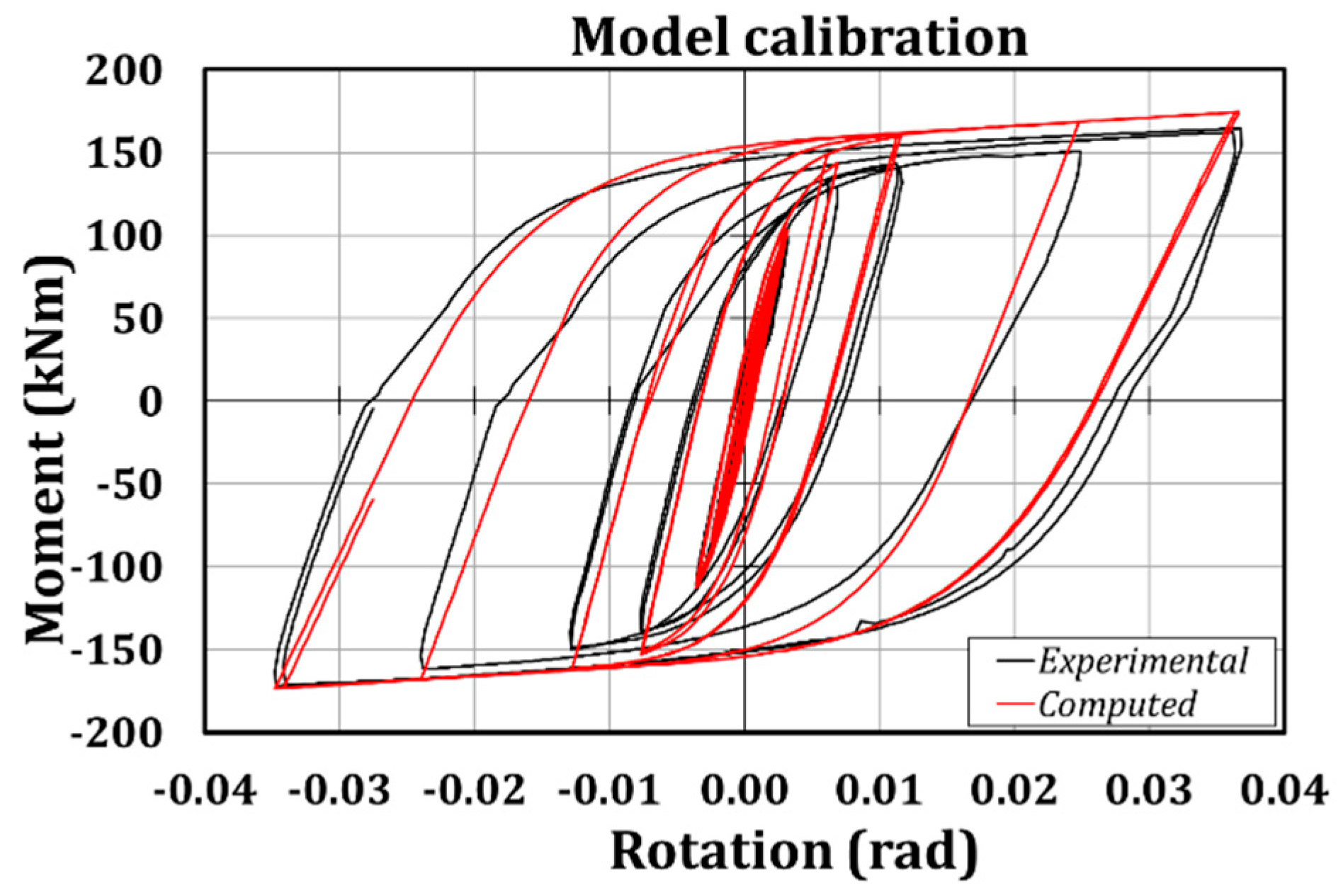
However, since the definition of the parameters which enter the smooth model [
49] are 22, and some of them cannot be simply defined referring to the mechanic behavior of the connection, it has been necessary to calibrate these coefficients basing on the results of a cyclic test of a beam-to-column sub-assembly endowed with the same geometric and mechanic properties of the joints mounted to the mock-up (
Figure 5). Such a preliminary experimental phase has been followed by the calibration of the needed parameters thanks to the MultiCal software [
50], which is based on the adoption of Genetic Algorithms in order to select the best combination of the parameters able to fit the experimental response. In particular, the initial flexural stiffness has been fixed equal to 41,688 kNm
2, the positive and negative cracking moments equal to 157 kNm, the positive and negative yield moments equal to 158 kNm, the positive and negative yield curvature equal to 0.096 rad, the positive and negative ultimate curvature equal to 0.193 rad, the positive and negative post-yield flexural stiffness equal to the 0.012% of the elastic corresponding value, the stiffness degrading parameter equal to 4.7, the ductility-based strength decay parameter equal to 0, the smoothness parameter for elastic-yield transition equal to 1.27, the parameter for the shape of unloading equal to 0.50, the slip length parameter equal to 0.07, the parameter for mean moment level of slip equal to 1.36 and finally all the parameter related to the exponent of gap-closing spring, the gap closing curvature and gap closing stiffness equal to 1.
Since the main aim of the paper is to show which could be the possible benefits related to the adoption of friction connections by means of the comparison with the numerical results related to the structure with RBSs, this paragraph will briefly summarize the main aspects which have allowed to validate the abovementioned numerical model of the structure with RBSs.
The first test was interrupted because, starting from 4 s (accelerogram time), undesired displacements at the base of the structure and the base of the shear wall occurred. Owing to this reason, the test was stopped at 7.94 s, just before the occurrence of the first large peak of the loading history. The reasons of the sliding have been ascribed to the gap existing between the anchoring holes of the concrete strong floor and the Dywidag bars used to fix the steel footings. This issue was solved bracing the footings and connecting the base of the structure to the reaction wall. Subsequently, the test was repeated and concluded successfully. The results of the first test have been recorded, but they should be analysed with some caution, as the sliding of the bases has influenced the dynamic response of the mock-up, its energy dissipation and vibration periods.
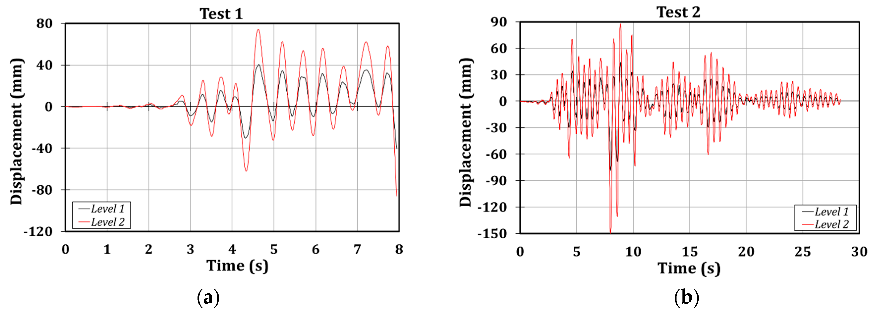
In all the tests the peak floor displacements and peak actuators forces occurred at the same instants. Up to the instant of 7.94 s a significant difference between the first and second test was not observed both in terms of peak displacements and force (
Figure 6). This demonstrates that the state of damage occurring in the first test was very limited.
The main results referred to Test 1 and Test 2 are reported in
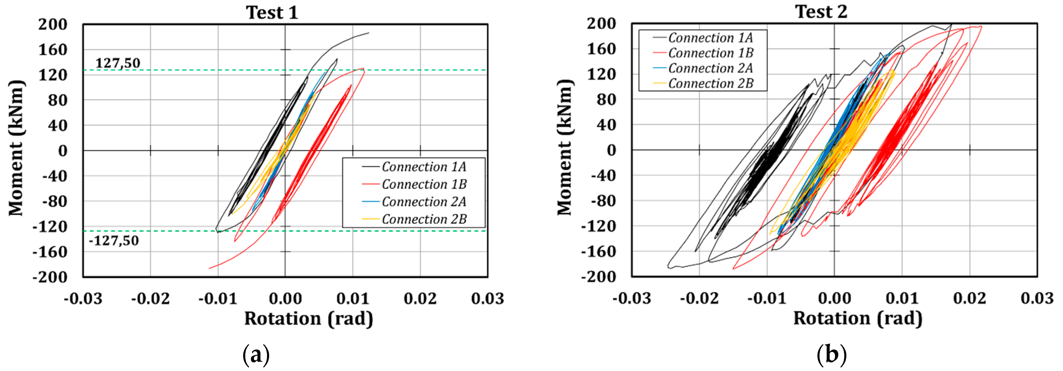
Table 4. It is possible to highlight the significant plastic engagement of the structural elements, since in the first test the inter-storey drifts achieved about 2%, while in the second test the inter-storey drifts achieved about 3%. The local measuring devices showed that RBSs located at the first floor exhibited higher damage than those at the second level.
As previously mentioned, the state of damage occurring in the structure was slight in the first test, due to the premature interruption, while in the second test the number of cycles experienced by the RBSs of the first level was much higher (
Figure 7). Moreover, it is worth highlighting that the rotation achieved by RBSs is not far from the EC8 requirement for joints belonging to DCH MRFs (35 mrad). Instead, the maximum bending moment (200 kNm) is higher than the design value defined considering the plastic zone fully yielded and strain-hardened (140 kNm). The consequence is that the overstrength factor suggested by EC8 (equal to 1.1) is largely underestimated.
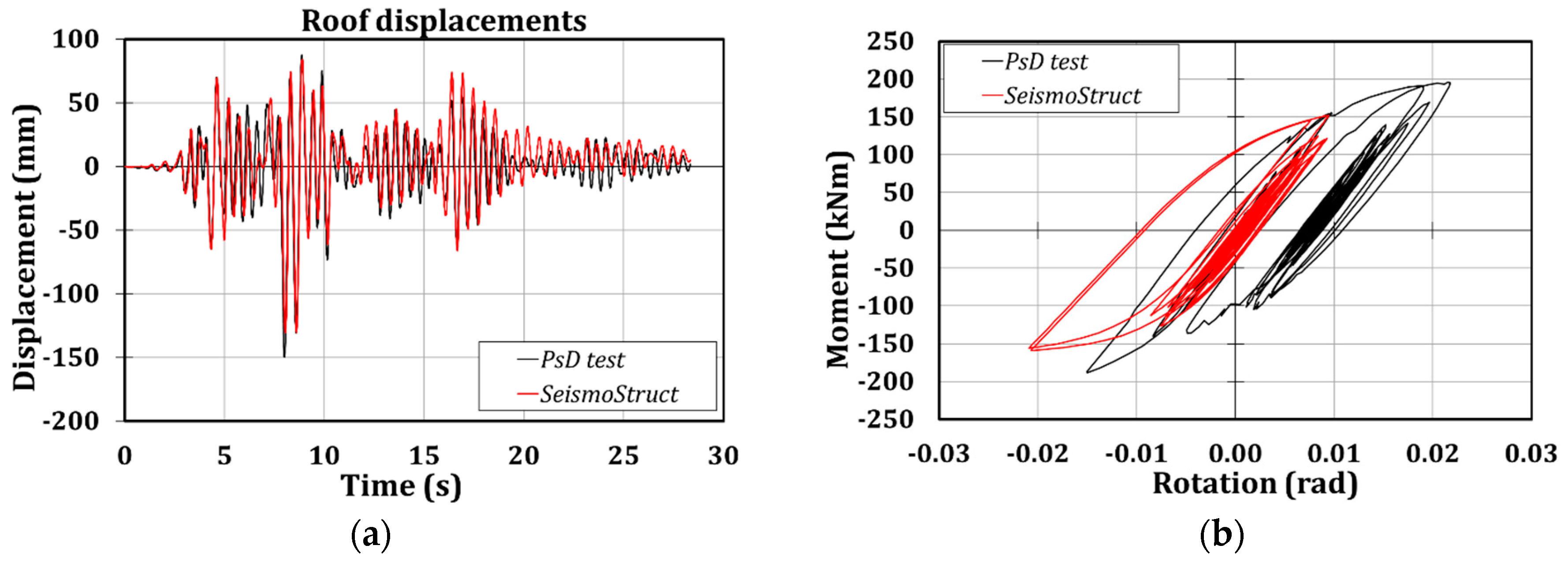
Moreover, it is possible to observe that the numerical model is able to accurately predict the global response of the structure since the scatters in terms of roof displacements between the experimental and numerical outcomes are of about 20% (
Figure 8a and
Table 5). Instead, the local prediction of the hysteretic behavior of the connection is not correctly foreseen, due to the higher resistance that the connections have exhibited, as it is clear from observing
Figure 8b, where the comparison of the moment-rotation curves referred to connection 1B are reported.
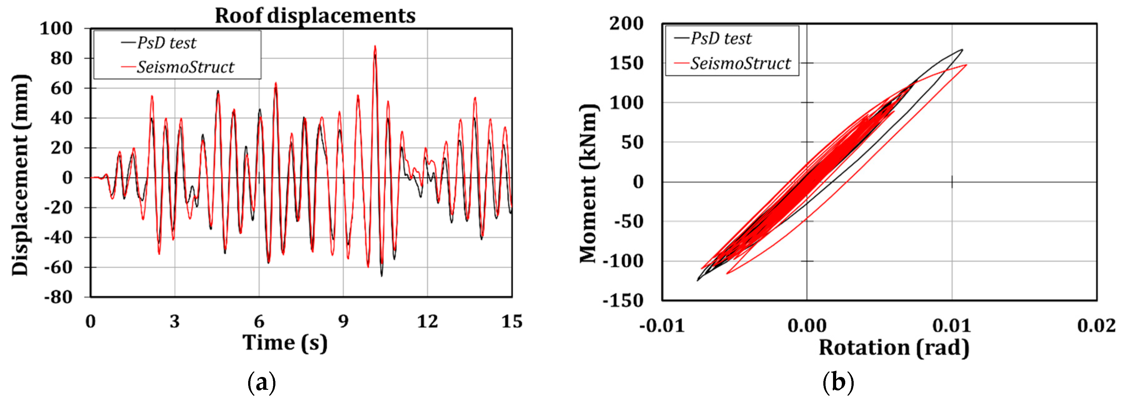
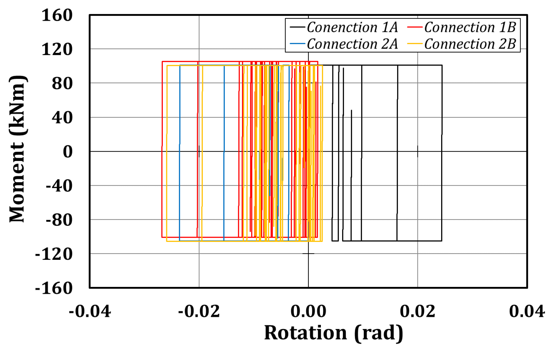
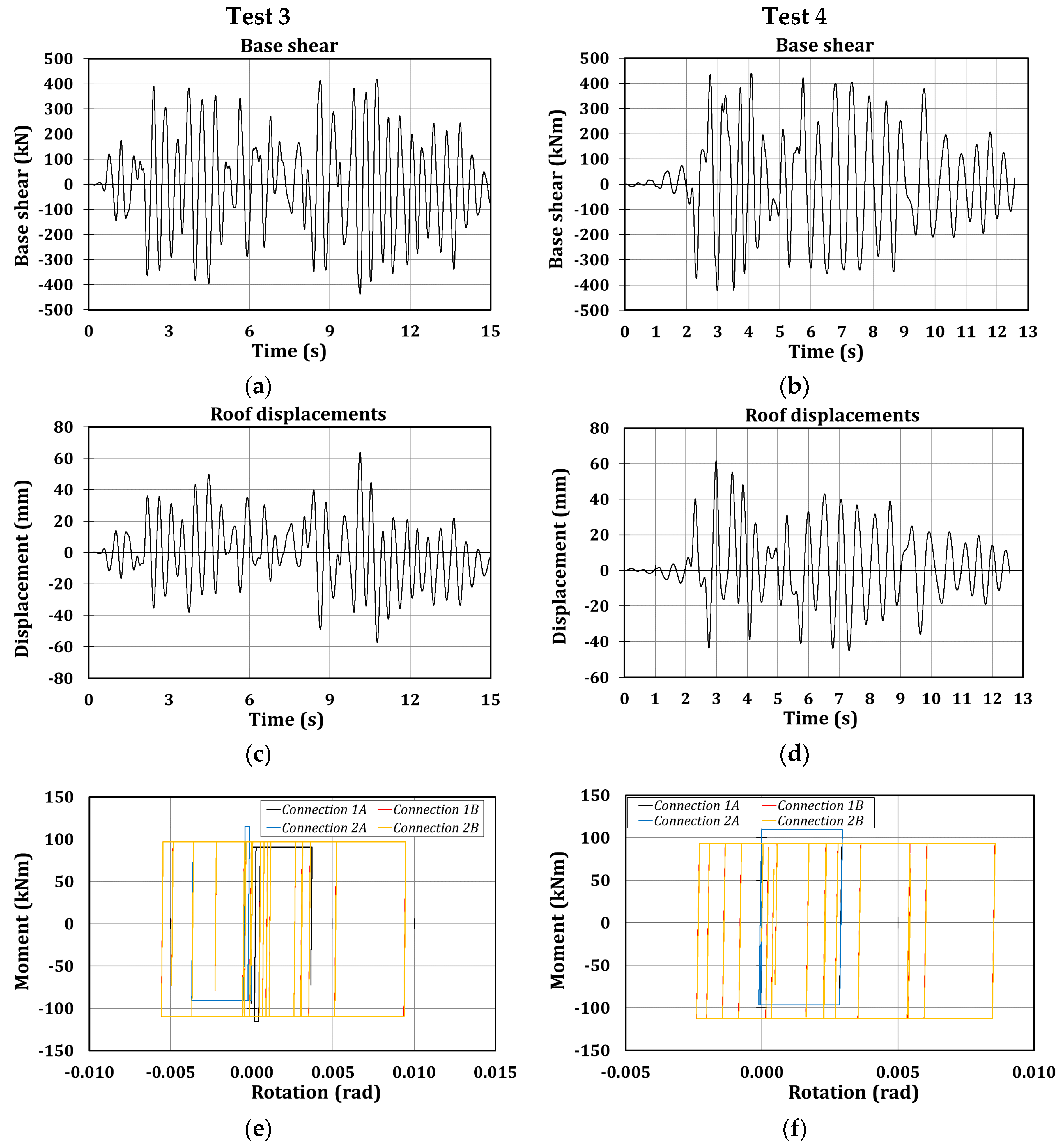
The third and fifth tests are referred to the same accelerogram, artificially obtained thanks to the SIMQKE tool. During the third test, the first-storey RBSs were engaged in plastic range achieving moments higher than 150 kNm (
Figure 9), while in the fifth test the whole structure behaved elastically (
Figure 10) because of the lower value of the applied peak ground acceleration. Nevertheless, in this case it is also possible to observe the reliability of the proposed numerical model since the maximum scatters referred to the roof displacements are of about 11% (
Table 6 and
Table 7). Instead, referring to the moment-rotation curves, it is clear that the numerical model is able to assess correctly the elastic behavior of the connections, while the excursion in the plastic range is captured with some approximations.
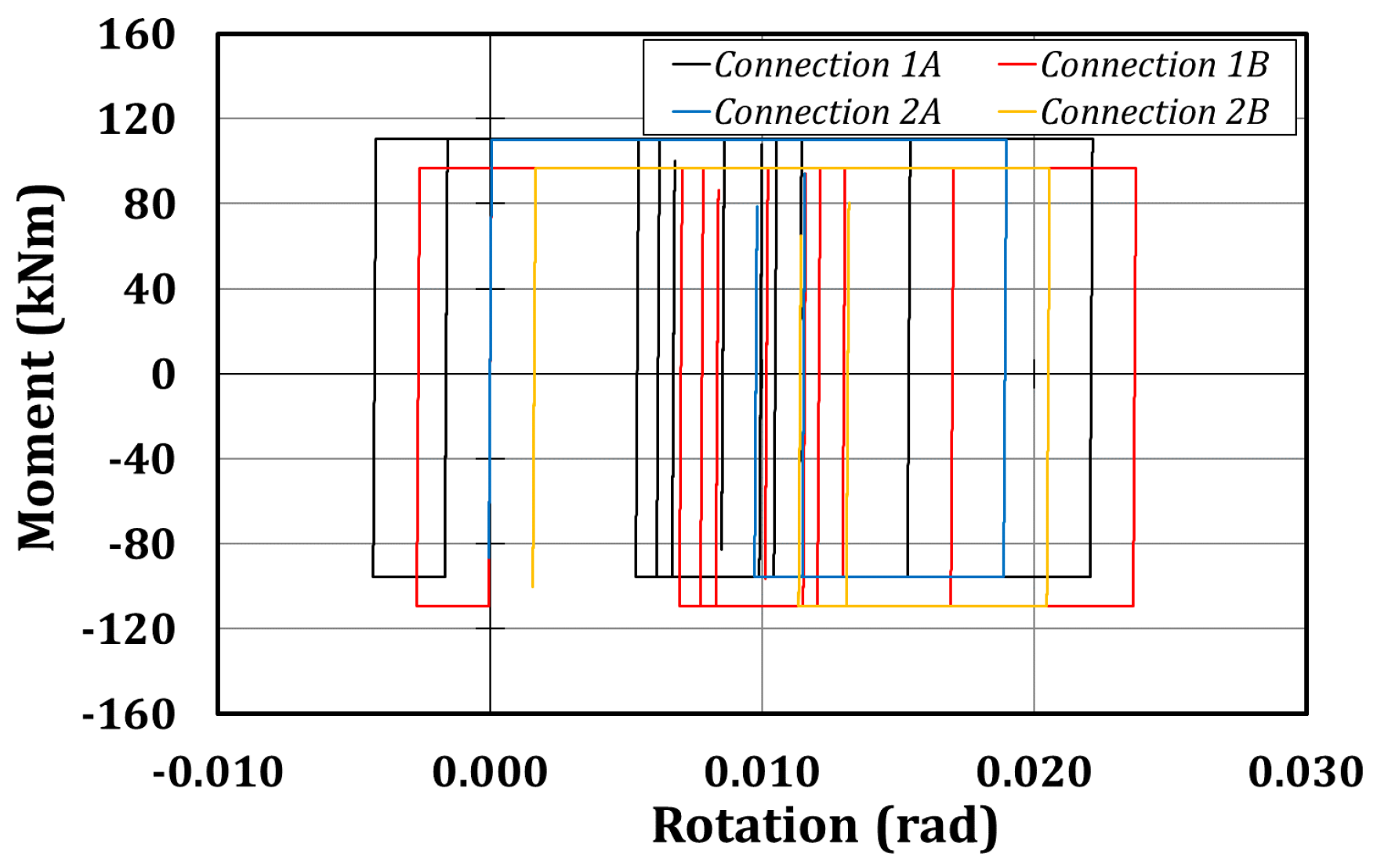
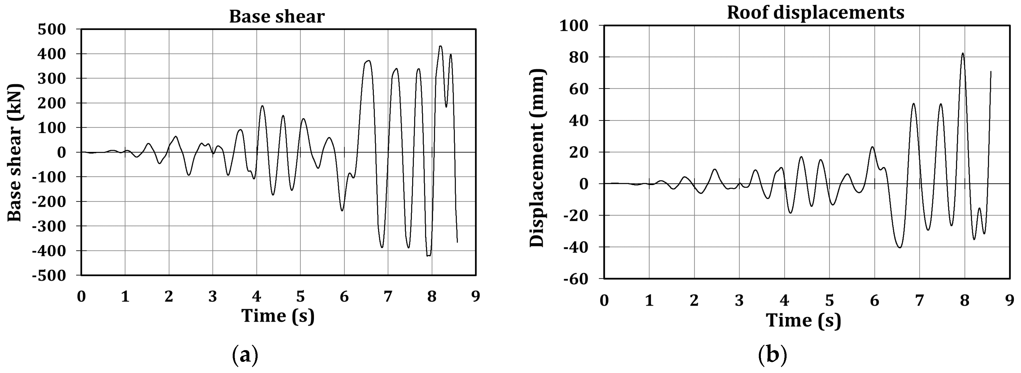
Conversely from the previous seismic inputs, the main feature of the fourth accelerogram is the occurrence of only one large-amplitude peak, inducing, as an aftermath, only one main excursion of RBSs in the plastic range (
Figure 11). The maximum inter-storey drift is about 3.6%, occurring at the peak accelerogram time, while in all the other instants the structure remained in the elastic range.
In such a case, differently from the previously examined tests, the global response of the connections is not accurately predicted (
Table 8). This is due to the fact that the parameters of the smooth links have been calibrated against the experimental results obtained, referring to a cyclic test of a beam-to-column sub-assembly. Such a kind of test is conceived to impose to the specimen many cycles with high amplitudes; instead, the one excursion in the plastic range induced by the only one peak of the accelerogram highlights the limits of applicability of the proposed approach, as already reported in [
50].
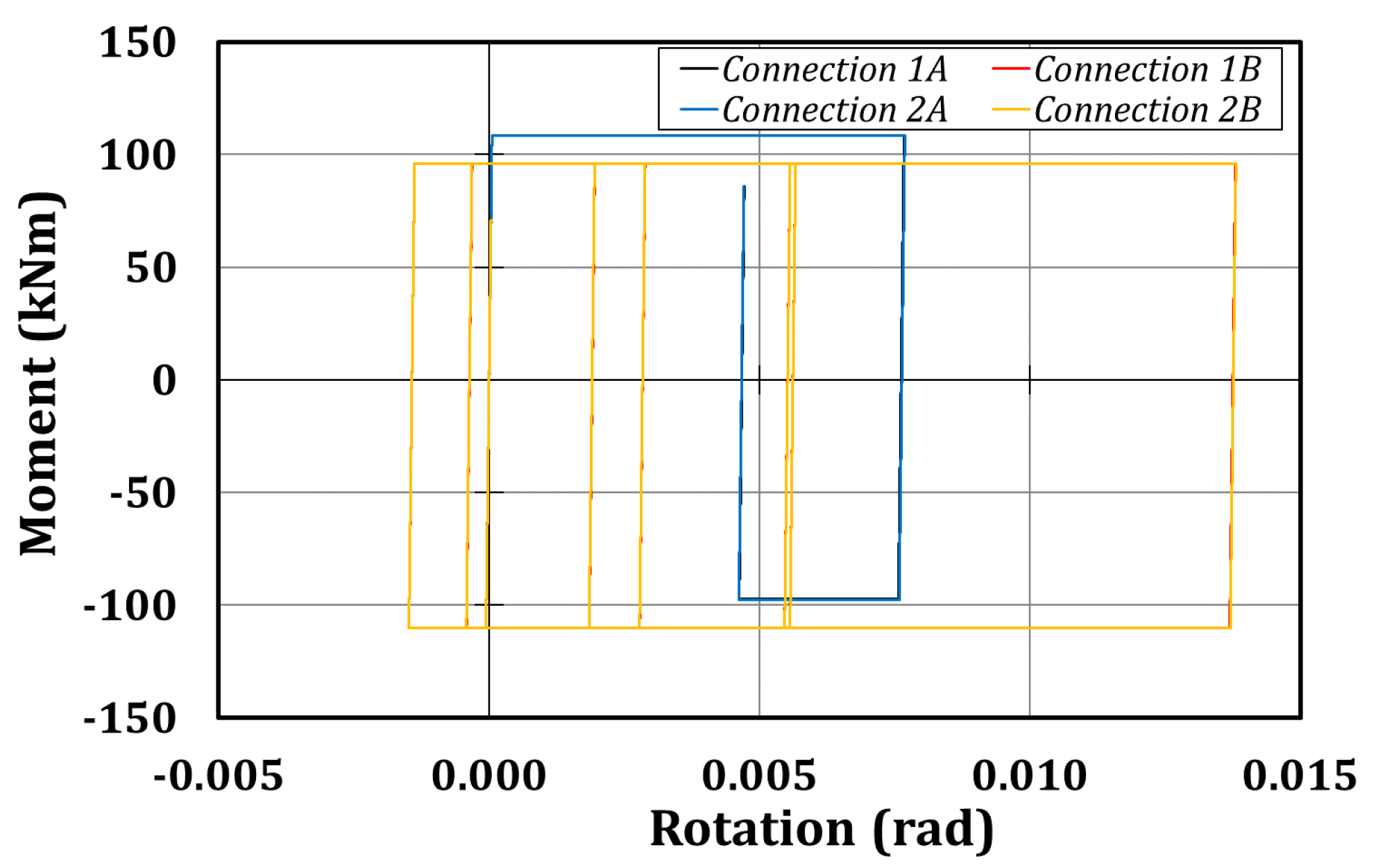
In Test 6, the structure remained in the elastic range, as it is clear from
Figure 12 and
Table 9, and so no further information can be collected.
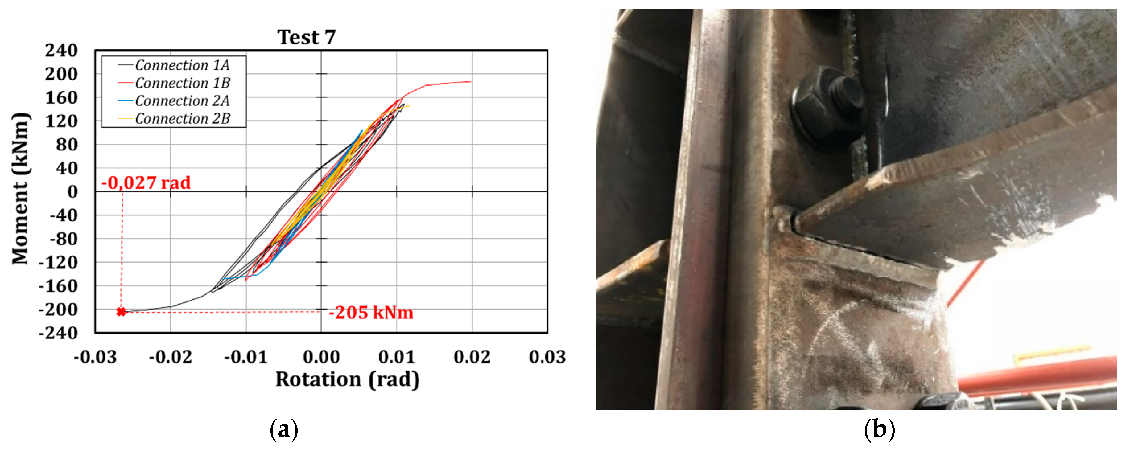
During Test 7, the failure of the structure occurred due to the crisis of two RBSs located on the two opposite frames of the first storey level, on the actuators’ side (
Figure 13). The local failure of the welds belonging to RBS-1A caused a redistribution of the actions, which led to overloading the parallel frame and inducing, as a consequence, the failure of RBS-1C. The unexpected high bending moment at column flange (205 kNm, 60% higher than the nominal resistance) and the limited fatigue life of the welding probably provoked the local collapse of RBS-1A (
Figure 13).
Also in this test, the reliability of the proposed numerical model is proven (
Figure 14 and
Table 10), since the scatters in terms of floor displacements and base shear are lower than 15%.
At the end of the first experimental campaign, it was possible to conclude that the maximum rotation experienced by the RBS connections (3%) is consistent with the benchmark value suggested by Eurocode 8 for high ductility class, equal to 0.035 rad, and that even though RBSs have been conceived to avoid brittle fractures at the welds, such a phenomenon could occur because of the cyclic fatigue exhibited by the joints.
Furthermore, it is worth highlighting that although the proposed numerical approach to model the tested structure is not able to correctly predict the local response of the dissipative connections, it is nevertheless able to accurately foresee the parameters related to the global seismic response of the structure, which are usually the parameters that codes rely on.
5. Numerical Simulation of the Second Experimental Campaign: Structure Equipped with Friction Joints
The second experimental campaign, consisting of carrying out pseudo-dynamic tests on the structure equipped with friction connections, has not yet been performed. For this reason, in this paragraph, the results concerning the numerical simulation of the mock-up will be reported.
The structure has been modelled thanks to the OpenSees software [
51], in order to have the blind prediction of the structural behavior, and to check that the expected actuators’ forces are compatible with their capacity. In
Figure 15, the FE model of the structure is reported. The applied approach consists of adopting both lumped and distributed plasticity sources; in fact, inelastic force-based elements, subdivided into at least 120 fibres, have been adopted to model the beams and the columns (spread plasticity approach), while the plastic behavior of the friction joints has been modelled thanks to rotational springs (lumped plasticity approach) whose yielding moment is equal to 103 kNm. The numerical simulations consisted of performing time-history analyses characterized by a time step equal to 0.01 s solving the equations of motion employing the Newmark algorithm, fixing the damping equal to 1%.
The analysis has been performed applying a sequence of five accelerograms: the same of the previous campaign, except for the partial tests in which technical issues occurred (
Table 11).
The first applied accelerogram is Imperial Valley, with a PGA equal to 1.10 g. As it is clear in
Figure 16, the maximum base shear is about 430 kN, while the maximum roof displacement is 141 mm. At the end of the test, the recentering of the structure is not ensured, and so it is expected that the structure has residual drifts. Such a result is justified by the fact that the friction devices are not characterized by pre-tensioned bars able to restore the initial configuration of the building at the end of a seismic event.
Moreover, the previous conclusion is consistent with the expected hysteretic moment-rotation curves reported in
Figure 17, since the rotations of the friction devices are not 0 at the end of the test. The maximum rotation is about 25 mrad, and the maximum bending moments are about 100 kNm, as imposed to the mechanical behavior of the devices. Furthermore, it is expected that the devices are activated many times during the seismic event, dissipating in such a way a high quantity of input seismic energy (about 6 kNm for connection 1A for instance).
Test 2 consists of simulating the behavior of the structure when subjected to Spitak accelerogram with PGA equal to 0.80 g.
Also in this case, the expected maximum values of base shear and roof displacement are of about 430 kN and 127 mm, respectively (
Figure 18), and residual drifts of the structure still remain. Instead, as it is clear in
Figure 19, a lower number of activations of the devices is expected; such an occurrence is justified by the fact that the accelerogram is characterized by only one main peak.
The third and the fourth tests, consisting of applying the artificial and Santa Barbara accelerograms with PGAs equal to 0.50 g and 0.80 g, respectively, are reported herein (
Figure 20), but they are not so interesting since it is expected that the structure behaves in the elastic range. In fact, at the end of these tests, no residual drifts are expected, the rotation of the devices is slower than 10 mrad, and they are activated a few times.
The last test, consisting of simulating the Coalinga earthquake with a PGA of 0.80 g, is partially performed, since it is interrupted at the same instant at which the RBSs exhibited the brittle fracture during the first experimental campaign. Also in this case, the maximum base shear is about 430 kN, while the maximum roof displacement is 82 mm (
Figure 21) and the hysteretic curves (
Figure 22) dissipate the same energy of the connections during Test 3 and Test 4, achieving rotations of lower than 15 mrad.
In
Table 12 and
Table 13, the main numerical results concerning the global and local response of the structure are shown. As it is clear from the tables, the first and the second test should engage the structure in the plastic range. In fact, the expected maximum peak floor displacements are about 130–140 mm, inducing, during the first test, a maximum interstorey drift of 3.4% at the second level, while connection 1A should achieve a maximum rotation of about 25 mrad. Furthermore, the analysis highlights that the friction devices should be activated in all the tests, since the maximum bending moments of about 100 kNm are always reached. The hysteretic curves have the classical rigid-plastic behavior of the friction devices (with the characteristic rectangular shape); it is important to highlight the asymmetric behavior of the connections since the maximum bending moment is about 90 kNm, while the minimum is about 100–110 kNm, depending on the considered test. This is probably due to the axial action arising, due to the force transferred by the actuators to the rigid decks.
6. Comparison of the Numerical Results of the Structure Equipped with RBS and Friction Connections
In the previous paragraph, the main expected characteristics of the global and local response of the structure were reported and discussed. Instead in this section, a comparison among the main results obtained by the numerical simulations referred to the structure with RBSs and the numerical analyses concerning the mock-up with friction joints is reported. Obviously, the comparison will rely only on accelerograms used to perform the numerical simulations with the friction connections.
In
Table 14, the comparison in terms of floor displacements and base shear are reported: it is possible to observe that the structure equipped with friction connections always exhibits lower base shear actions (in most cases, about 60% and 70% of the corresponding values related to the structure with RBSs) reducing, in such a way the stress distribution in the structural members. This is due to the limited bending moments that the structure equipped with friction devices can transmit to the columns. Instead, this trend cannot be observed referring to the peak floor displacements, which still remain very close to the corresponding values of the structure with RBSs.
Moreover, friction connections make the structural behavior elastic between two following peaks of the input motion: this is the reason for the reduced displacement range observed throughout the tests. The last phenomenon has a general validity for all the tests, but it is reported for Test 1 in
Figure 23. Furthermore, the figure highlights that friction devices do not guarantee the self-recentring of the structure.
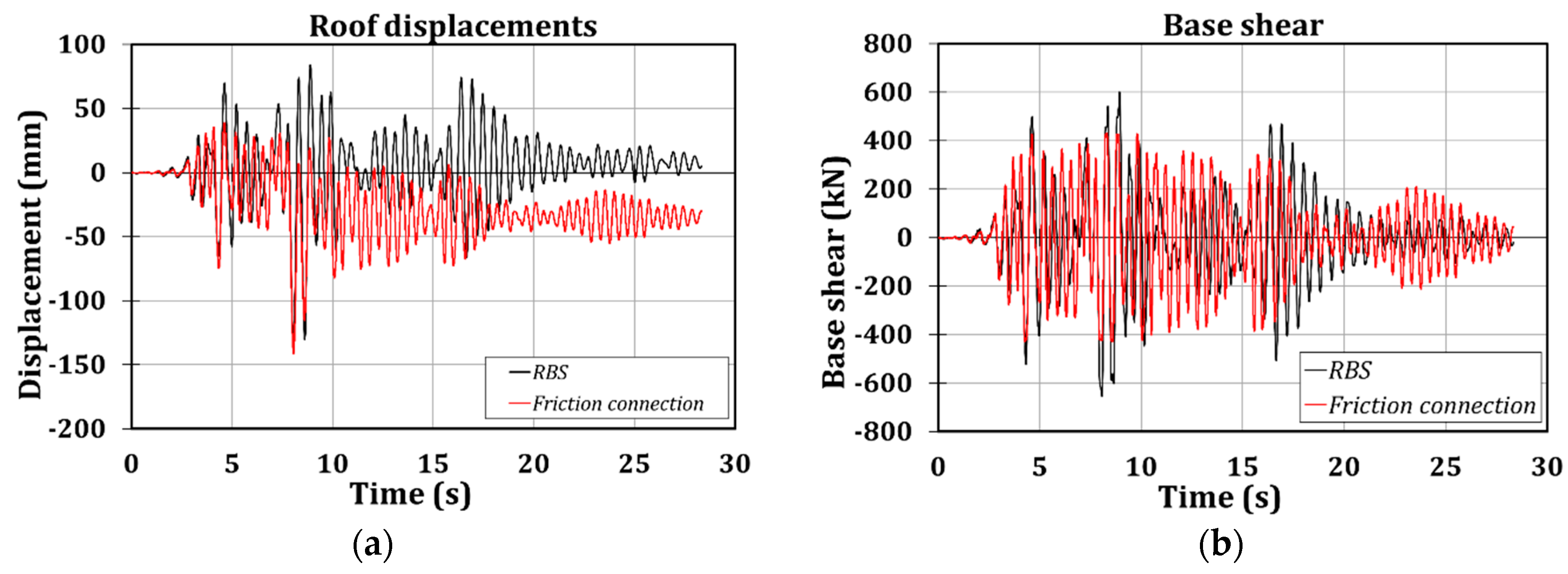
For the sake of simplicity, the local structural behavior exhibited by the analysed connections is reported concerning the most exploited connection for which no technical issues have occurred; the connection 1A is the chosen one, and the comparison is made referring to the Imperial Valley earthquake with PGA equal to 1.1 g. The reasoning discussed for this connection and input motion is analogous for all the other ones. In
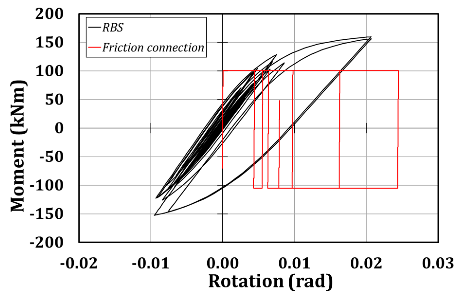
Figure 24, it can be observed that the RBS connection is able to withstand a higher bending moment (about 150 kNm compared to 100 kNm), and to sustain a similar rotation demand (about 0.025 rad). Nevertheless, it can be observed that friction joints are able to stress the structure at low levels and to make it stiffer, without preventing the possibility of dissipating a high amount of energy. The previous statements are valid for connections belonging to the first floor, while those ones located at the second level mainly show an elastic behavior, and for this reason are not reported herein.

 ,
, 


