1. Introduction
In recent decades, while the use of underground space by humans has increased, underground tunnels have been used extensively in infrastructure. There are many types of urban underground tunnels, including water supply, drainage, gas, heat, electricity, communications, radio and television, industry, etc. The seismic waves will be dispersed as they spread to the ground and the outer and inner surface of the tunnel. Under the superposition of incident waves and these scattered waves, dynamic stress concentration will occur around the tunnel, which can cause damage to the tunnel structure [
1]. However, the traditional concept is that underground structures are safe during earthquakes. It was not until the Kobe earthquake in Japan and the Wenchuan earthquake in China, both of which caused severe damage to underground structures, that concerns were raised about the seismic resistance of underground structures [
2,
3]. Hence, the need to study the seismic resistance of tunnel engineering. In order to understand and reveal the influence of seismic waves on underground structures, researchers have carried out a lot of research work on seismic wave scattering using numerical methods [
4,
5,
6] and analytical methods [
7,
8,
9]. Although numerical methods are more suitable for solving complex and realistic configurations, analytical solutions have inherent meaning, not only revealing the physical process of wave scattering but also serving as a benchmark for calibrating numerical results. Since Baron used the integral transformation method and the wave function expansion method to give the analytical solution of the cylindrical cavity to the compression wave pulse scattering problem, the wave function expansion method has become the main analysis method to study the wave scattering problem [
10]. So far, whether in the field of traditional seismic research or in the field of smart materials, the wave function expansion method has played an important role [
11,
12,
13,
14,
15].
The idea of using the great arc assumption method to deal with the elastic wave scattering problem was first mentioned in the article of Sheidl et al. They suggested using a circle with a large radius to approximate the straight boundary of the half-space near the obstacle so that the scattered wave at the straight boundary can be converted into the scattered wave at the large circle boundary, which can then be solved by mathematical formulas [
16]. Lee et al. improved this method by replacing the non-convergent ordinary series with the Fourier-Bessel series and obtained satisfactory results [
7]. Then, the researchers studied a series of scattering problems using the wave function expansion method based on the large arc assumption method [
17,
18,
19]. On this basis, Jiang studied the scattering of plane waves with a lined cylindrical cavity in a poroelastic half-plane by adding Biot’s poroelastic theory [
20]. The successful application of the complex variable function theory to the problems related to elastic wave scattering and dynamic stress concentration in any hole in the whole space makes the great arc assumption method easier to use [
20,
21,
22].
Many strata in nature have undergone alternate deposition, magmatic intrusion, and multiple tectonic activities during the long geological age, resulting in alternate layers of soft and stiff soil layers. This is different from when the earth is assumed to be a whole elastic half-space, when considering the influence of the composite soil layer, the boundary conditions become more complex. Few pieces of literature show that scholars from various countries have given ideal methods to solve this kind of problem and discussed the scattering problem of tunnel lining in composite soil. However, the wave function expansion method combined with the great arc assumption method is an ideal analytical method to solve the problem of elastic wave scattering by tunnels in composite soil layers. In our previous research work, the two soil layers with large differences in rock and soil mechanics and engineering geology were simplified into the covering soil layer and the lower soil layer. The dynamic response of a circular lined tunnel [
23] and a partially debonded circular lined tunnel [
24] in the covering soil layer under the action of SH waves are studied. Accurate results are obtained, which can provide theoretical reference for the seismic design of tunnels. Our previous studies have considered tunnels within the covering soil layer, while tunnels in actual projects are not only within the covering soil layer but also in the soil layer below the covering soil layer. Therefore, this paper further investigates the dynamic stress concentration in circular tunnels under SH-wave interference in the soil below the covering soil layer.
2. Model and Analysis
The two-dimensional model to be studied is shown in
Figure 1. It contains two kinds of soil layers, and the lower soil layer contains a circular lining tunnel. The circular lined tunnel is disturbed by the steady-state SH wave with an incident angle of
. According to the partition method, we divide the model into three domains. The lower soil layer is Domain I, the covering layer is Domain II, and the lined tunnel is Domain III. A Cartesian coordinate system,
, is established at the center of the large arc; a Cartesian coordinate system,
, is established at the center of the lining. The hypothesis parameters are as follows:
The density, the shear velocity, and the shear modulus of the lower soil layer: , , .
The density, the shear velocity, and the shear modulus of the covering layer: , , .
The density, the shear velocity, and the shear modulus of the lined tunnel: , , .
The inner radius and outer radius of the lined tunnel: , .
The radius of the upper and lower boundary of the covering layer: , .
The thickness of the covering layer: .
The distance from the center of the circular lining to the lower boundary: .
The upper boundary of the covering layer is marked as , the lower boundary is . Using the large-arc assumption method, the upper and lower boundaries of the covering layer are approximated using concentric arcs, each with a large radius; the upper boundary becomes , and the lower boundary becomes . The inner boundary and outer boundary of the lined tunnel are and , respectively. Introducing complex variables as follows and , where = 1, 2. So, the complex coordinates and correspond to the Cartesian coordinates and .
The wave potential function of incident plane SH wave can be expressed by Fourier-Bessel series under coordinate
as
where
is the amplitude of the incident SH waves and
is the Bessel functions of order
n. It is worth noting that the point in the parentheses of the Bessel function represents the argument. Since the argument here is variable, a point is used instead. In addition,
in the argument is the wavenumber with
, shear wave velocity
,
is the circular frequency of the displacement.
For the circular tunnel lining, scattered waves propagating outward will be generated at the interface between the tunnel lining and Domain I. They can be expressed as series forms:
where
is the unknown coefficient to be determined and
is the Hankel function of order n of the first kind. Moreover, the standing wave is generated inside the lining, which is composed of
which scatters outward from the inner boundary and
which scatters inward from the outer boundary. The standing wave can be expressed as series forms:
where
and
are the unknown coefficients of the standing wave to be determined.
For the covering layer, scattered waves will be generated at the boundary
and
. They are
which propagates downward from boundary
,
which propagates upward from boundary
, and
which propagates downward from boundary
.The series form is as follows
So far, the above wave fields need to meet the following boundary conditions. They are the continuous displacement on
, the continuous radial stress on
, the traction free on
, the continuous displacement on
, the continuous radial stress on
and the traction free on
. Converting the expression of the wave field to the corresponding complex coordinates is the premise for calculating the unknown coefficients. According to the conversion relation
, we can get the following wave field expression.
According to the boundary conditions, we can get an infinite linear equation system with unknown coefficients
,
,
,
,
and
.
where the corresponding radial stress is of the following form,
The coefficient matrix of the system of equations (Equation 10) consists of 6 rows and 6n columns. Since n is infinite, the matrix does not reach full rank and thus the unknown coefficients cannot be obtained. Multiply the two sides of the infinite algebraic equation by ( under coordinate and under coordinate ) with and integrate on the interval . In this way, the coefficient matrix is expanded into an infinite matrix with 6m rows and 6n columns. According to the attenuation characteristics of scattered waves, n (m = n) is taken to a finite value under the condition of guaranteed accuracy. At this point, the above equation is transformed into a finite term linear equation. Furthermore, the unknown coefficients , , , , and are obtained for the finite term linear equations.
3. Results and Discussion
The stresses at or near the boundary of the lining can be significantly phantom under the disturbance of SH waves. For this kind of problem, the dynamic stress concentration factor is usually used to reflect the degree of stress concentration. The dynamic stress concentration around the lining can cause a brittle fracture or fatigue cracking, and understanding the dynamic stress distribution around the liner can be of great help to the structural design. In reference [
25], the dynamic stress concentration factor (
) is defined as the ratio of the hoop stress to the incident wave stress amplitude:
where
The numerical example investigates the dynamic stress concentration on the inner and outer surfaces of a circular concrete lining when the SH wave is incident in the vertical direction. Since the studied geometric model is symmetric in the y-axis direction, the dynamic stress distribution diagram on the lining surface under the action of SH wave vertical disturbance is also symmetric in the y-axis direction. To facilitate numerical calculation and analysis, a dimensionless wave number consisting of wavenumber and lining inner wall radius is introduced. Define the ratio between parameters , , , , , and . C30 concrete used materials are applied to create the lining, with density and shear velocity . Domain I is sandstone of density and shear velocity . So and . According to the different geological and mechanical parameters of the covering layer, the following two different groups of parameters are assigned to Domain II, respectively.
A: (The covering layer is “softer”) Domain II is coal of density and shear velocity , then , .
B: (The covering layer is “stiffer”) Domain II is dense limestone of density and shear velocity , then , .
Set
, then the parameters of the upper and lower soil layers are the same, so there is no boundary T
D. Accordingly, the problem studied in this paper is reduced to the problem of scattering of SH waves by a circular lining in a single medium half-space, which was solved in previous work by using the wave function expansion method combined with the image method [
9].
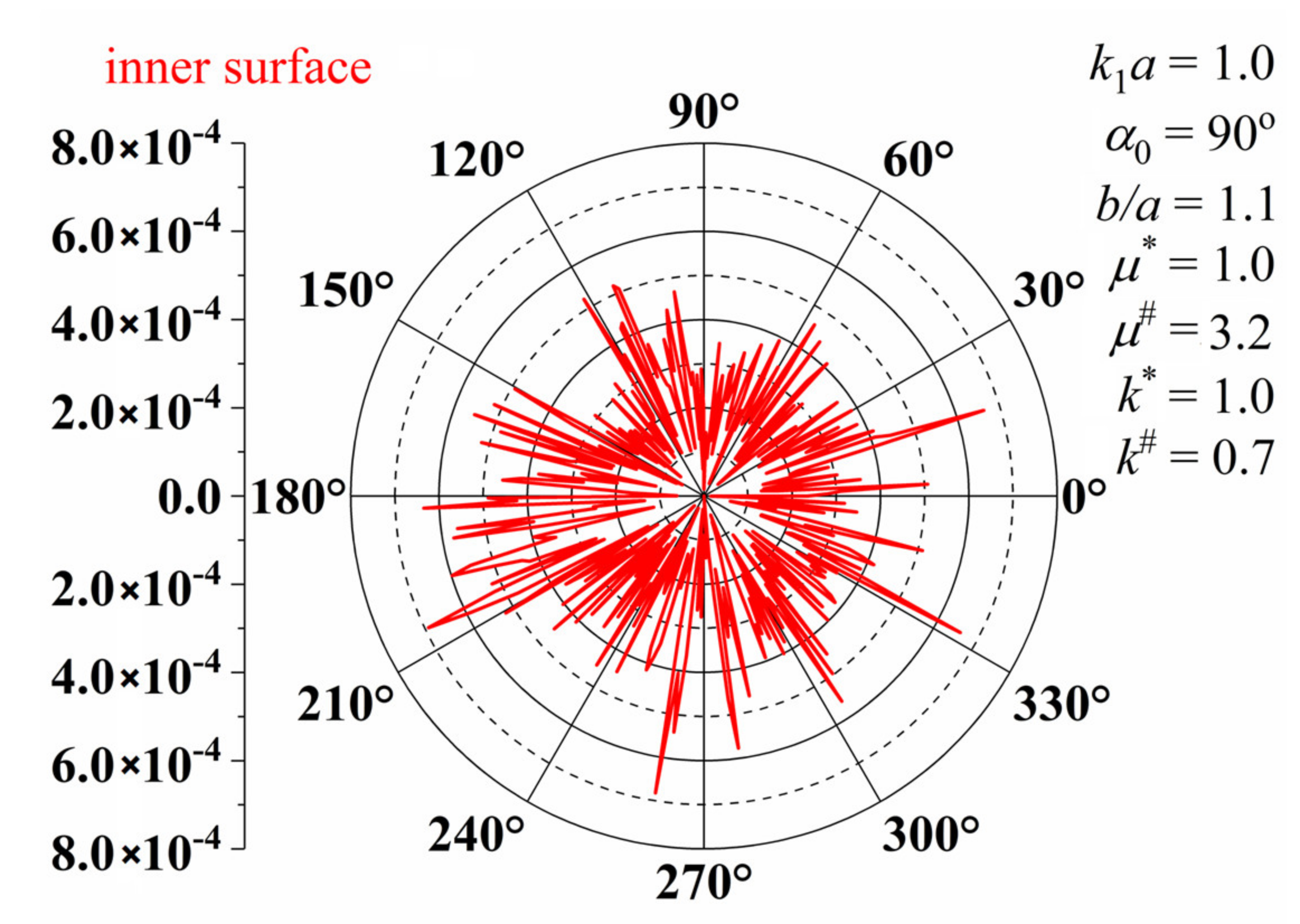
Figure 2 shows the DSCFs around the inner surface of the circular lining for
,
,
,
,
and
when
, respectively. Through careful comparison, the results are basically consistent with the previous results.
The Bessel series has good convergence. Although the convergence slows down with the increase of
, the very small truncation coefficient can meet the accuracy requirement. The convergence of the numerical results can be substituted into the equation by the coefficients found, and tested with the traction free conditions. Dimensionless residual stress was introduced to describe the accuracy of series solutions. We define the residual radial stress of the inner surface as follows:
Figure 3 is the residual radial stress diagram of the inner boundary of the lining when
Figure 2 is obtained. It can be seen that the order of magnitude is around
. This can show that accuracy can be guaranteed in the numerical calculation process.
The size variables are the covering layer thickness h, the distance from the center of the circular lining to the lower boundary d, and the outer radius of lining b. Let us first discuss the influence of b under the assumption of
and
.
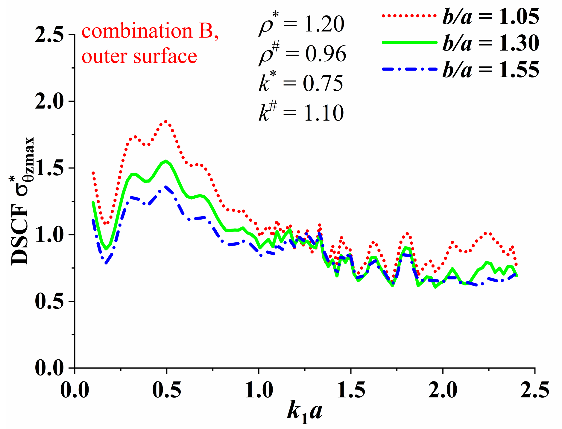
Figure 4 and
Figure 5 respectively show the variation of the
of the outer boundary of the concrete lining in the sandstone layer with the incident wavenumber
under the geological combination A and B. The parameters
and
of the circular lining are the same, while the parameters
and
of the two covering layers are different. The purpose of the first analysis of this part is to find the frequency band where the concrete lining is most sensitive to the dynamic response of the incident wave under the two geological combinations. On the one hand, according to
Figure 4 and
Figure 5, this provides “critical frequencies” for the discussion of subsequent issues in this article. On the other hand, it can provide a theoretical basis for how to reduce the impact of dynamic stress concentration in engineering design. In
Figure 4, the
of the outer surface of the lining increases gradually along with
in the geological combination A, reaches a peak when
, and then follows a trend of decreasing vibration. The effect of the change in lining thickness on
is not very obvious when
. When
, increasing the thickness of the lining is beneficial for reducing
. Comparing
Figure 4 and
Figure 5, we can find that the
of the lining outer surface in the geological combination B reaches peak at
. When the SH wave is incident at a low frequency (
), increasing the thickness of the lining will suppress the increase in the maximum dynamic stress. So, it can be clearly seen that the difference from the half-space problem is the difference in the stiffness of the cover layer, which will significantly affect the frequency band at which the dynamic stress response of the lining is maximum. The stiffer covering layer has a shielding effect on the influence of SH on the tunnel, and it can also be said that the softer covering layer has an amplification effect on the dynamic stress concentration factor. Next, take
in
Figure 4 and
in
Figure 5 as the “critical frequency” to analyze the distribution of DSCFs around the inner and outer surface of the lining.
Figure 6 illustrates the dynamic stress concentration around the surface of the concrete lining in the sandstone layer when the geological combination A is taken (that is, when the SH wave is incident perpendicularly from the sandstone layer to the coal layer). At this time, the covering layer is relatively soft. It can be seen from figures that when
, the distribution of the dynamic stress concentration factor of the outer surface is elliptical,
appears at about 0° and 180°. When the incident frequency
increases to 0.3, the increase in the
of the outer surface is very substantial compared with the case when
. When
, the overall value becomes smaller, but the
distribution shape of the outer surface changes considerably. It can be seen that the lining under geological combination A is more sensitive to the dynamic response of low-frequency incident waves. This may be caused by the resonance between the structure and the site under low-frequency conditions. By comparing the distribution of
under different lining thickness conditions, it can be found that
of the outer surface decreases as the thickness of the lining increases under the incident waves of three frequencies. Under the same incident frequency, it can be clearly observed that the value of
near the inner surface of the lining is mostly larger than that near the outer surface. This indicates that in current geological combination conditions, it is necessary to pay attention to the concentration of dynamic stresses on the inner surface. When
, the increase in lining thickness has little effect on the
of the inner surface, while when
, the
of the inner surface can be slightly reduced by increasing the thickness of the lining. Therefore, the existence of the covering layer makes the distribution of
in the inner and outer surfaces of the lining more complicated than the problem in the half-space. It cannot be said in general that the thicker the lining, the more beneficial it is to reduce
. For linings of different thicknesses, it is necessary to take special measures in the engineering design to strengthen the weak areas of the inner and outer surfaces.
Figure 7 shows the dynamic stress concentration around the surface of the concrete lining in the sandstone layer under geological combination B. At this time, the SH wave is incident perpendicularly from the sandstone layer to the dense limestone layer. The
around the outer surface decreases as the thickness of the lining increases under the incident waves of three frequencies. Compared with
Figure 6, it can be found that the dynamic stress distribution of tunnel under the condition of geological combination B is more complex when
. It can be obtained from the figures that the same rule as in the case of geological combination A is that the overall value of
in the inner surface of the lining is larger than that in the outer surface at mid- and low-frequency incidents. The increase in the thickness of the lining has little effect on the
around the inner surface. The difference is that when the incident frequency is higher, the increase in the thickness of the lining is more obvious for reducing the
around the inner surface.
Then we discuss the influence of the distance from the center of the circular lining to the lower boundary d in the case of the covering layer thickness
and
.
Figure 8 and
Figure 9 show the variation of the outer surface of the lining with
under the condition of geological combination A and B, respectively. The “critical wavenumber” under each geological combination is selected for analysis. It is obvious that
changes periodically with
. In addition, by comparing
Figure 8 and
Figure 9, it is obvious that the maximum value of
under geological combination A is larger than that under geological combination B. Under the geological combination A,
decreases slightly with the increase of h, while under the geological combination B,
increases slightly with the increase of h.


