Article

Maritime Autonomous Surface Ship’s Path Approximation Using Bézier Curves

1
Gdynia Maritime University, ul. Morska 81-87, 81-225 Gdynia, Poland
2
Jan Kochanowski University in Kielce, ul. Uniwersytecka 7, 25-406 Kielce, Poland
*
Author to whom correspondence should be addressed.
These authors contributed equally to this work.
Symmetry 2020, 12(10), 1704; https://doi.org/10.3390/sym12101704
Submission received: 18 September 2020 / Revised: 6 October 2020 / Accepted: 13 October 2020 / Published: 16 October 2020

Abstract

:
This work is devoted to the second order rational Bézier curve coefficients estimation. We present the methodology of unique coefficients for each type of ship computation. In the presented formulas of ship’s length, a draft and angular path combined with a drift path are used. This approach leads to the simplest and most accurate Maritime Autonomous Surface Ships (MASS) path modeling. Three rational curve control points are waypoints (WPT). Using WPTs as curve control points allows integrating a trajectory intuitive for the navigator with a path predicting model used as a reference in the control system. Research was done based on real-time data originating from the MASS autonomous trajectory tracking system. The presented mathematical modeling tool may be treated as the best way of future trajectory prediction due to low computation power required.

1. Introduction

Maritime Autonomous Surface Ships (MASS) need information about their future path, especially during safe trajectory determination and model-based control application. The problem of trajectory modeling and prediction is not trivial. In order to get a feasible path, one needs to take into account the controlled object dynamics. During trajectory estimation physical constraints of an autonomous ship have to be satisfied. They determine the minimum curvature radius, tangent acceleration and all three velocities (longitudinal, transversal and angular). Moreover, the generated trajectory needs to be smooth and in the case of the ship her velocities along all three axes need to be constant.
For navigators, the waypoints’ coordinates definition is the easiest and natural way of trajectory determination. When plotted on a chart or the Electronic Chart Display and Information System (ECDIS), they are connected with straight line segments. But, due to ship dynamics, the trajectory defined in this way is not feasible. When applied to MASS it generates big errors in control signals on turns, which are undesirable. These errors may be minimized using model-based control strategies combined with reference generation optimization.
Model Predictive Control (MPC) is one of the model-based control strategies used to track a predefined trajectory. There are several methods used for reference generation. An off-line trajectory generation scheme was proposed in [1]. Smooth trajectories are generated based on circle-segments, generalized paths and bi-elementary paths taking into account specific actuator constraints and field geometry. But this approach may be used only when there is no possibility to collide with other moving objects and it is not applicable for MASS which requires on-line reference generation and smoothing. Trajectory planning as combination of the potential-field like function and reachability sets was presented in [2], where artificial potential field maps surrounding the region with all obstacles combined with target trajectory generation subsystem were used to identify a reachable safe trajectory. The trajectory generation subsystem combines potential fields with vehicle dynamics in order to deliver reference as a state set. This method gives feasible references and is real-time applicable. It may be applied to ship overtaking, but there is a difficulty in recalculation from waypoints (WPT) to the potential field form. The MPC trajectories generation method proposed in [3] introduces general-purpose path- and trajectory planners. The planned trajectories conform to the actuator capabilities and map decisions about constraints and optimization parameters into a functional system. Unambiguous reference is generated based on static environment and vehicle’s state. Neither other moving objects nor a reference change during vehicle operation are taken into account, which disqualifies the above-described approach from using it in MASS.
Geometrical on-line modeling approaches have also been described in the literature. Xi and Baras in [4] proposed angular acceleration control instead of angular velocity control used in the Dubians’ optimal trajectory, where a vehicle is forced to stop at each path connection point. This approach gives a possibility of smooth reference generation based on a set of WPTs and obstacle avoidance. This method is applicable for wheeled autonomous vehicles, where no sideways slip is taken into account, which prevents its direct application in MASS. Dynamic path planning based on a B-spline template with minimizing the curvature of a path in 3D space is described in [5]. Continuity of the curvature makes a trajectory smooth and prevents the controlled object from stopping at discontinuities—WPTs. This method is interesting and promising for use in MASS, but requires solving the problem of a safe channel definition for instantaneously changing safe trajectory reference generated by the ship’s anti-collision subsystem. Shi et.al [6] proposed connecting of the rapidly-exploring random tree (RRT) with the CC Steer algorithm combined with cubic polynomial global path approximation. The RRT algorithm plans an optimal collision-free path in the current environment, the CC Steer algorithm smooths it and cubic polynomial approximation allows for vehicle dynamics incorporation. The proposed algorithm should be enhanced and should take into account objects moving in the vicinity of their own ship as well as allow modifying the generated trajectory in order to be used for ship’s reference generation.
The moving Window Blocking (MVB) scheme is a strategy, where inputs are blocked and shifted each time step [7]. In this concept the time-dependent blocking matrix is used, which provides stability and feasibility in a closed-loop control. This scheme may be directly applied to a reference trajectory given as straight line segments connecting consecutive WPTs. The only difficulty is determining the length of the time window, which should depend on the vessel’s turning angle, as well as the maneuver path advance in conventional MPC trajectory tracking.
After the analysis of the reference trajectory generation methods, it seems that the most promising combination is MPC with an external feasible trajectory predictor. The ship’s path may be modeled as:
ship motion pattern based on the Latent Dirichlet Allocation model [8], which is based on trajectory datasets represented as limited series of motion words and needs big amount of data to give reliable model;
probabilistic model of the ship handling behavior patterns in the Automatic Identification System (AIS) data using the sub-trajectory clustering algorithm [9], where the AIS data is processed to get ship handling behavior basics;
spline model for trajectory estimation based on the AIS data [10], where AIS data needs to be filtered and then may be used to map ship’s maneuverability;
deterministic model based on the concept of a predefined trajectories database containing safe and optimal paths of a ship [11];
model determined by density-based spatial clustering of applications with the noise (DBSCAN) algorithm combined with the Artificial Neural Network learning relationship of turning regions and generating a feasible route based on massive AIS data [12],
using Bézier curves [13], which seems to be the least computationally complex and parameterizable.
Bézier curves in path modeling allow taking into account ship dynamics. Hassani and Lande [13] proposed generation of a feasible paths set and assignment of a cost function to each of them. They used differential flatness property of the vehicle to reconstruct all states of the vessels during a maneuver in constrained waterways. They used 5th order Bézier curves and treated control points as design variables during the optimization process. Bézier curves are also popular in mobile robots, where a feasible path is also consistent with vehicle dynamics. Yang and Choi [14] used a cubic Bézier curve to make an S-curve path. Choi et al. [15] used Bézier curves as a seed function for the path planning algorithm as an alternative to cubic splines. This approach, involving non-linear optimization tasks, allows for collision avoidance. Cubic Bézier curves are also used for intelligent wheelchair door passing [16]. Control points are determined using optimization methods and mechanical constraints of the wheelchair are satisfied. Temporal Spatial cubic Bézier curves are used for simultaneous arrival of multiple unmanned vehicles path planning [17]. A smooth trajectory with the continuous radius along the entire path is generated and control points are selected by the genetic algorithm.
In all the mentioned above applications Bézier polynomial curves of 3rd and higher order are used for unmanned or autonomous vehicle path estimation. The obtained paths are feasible, because vehicle dynamics is taken into account during a path generation process. Therefore, it was decided that Bézier curves would be used to predict a future ship trajectory for the control purpose.
The aim of this work was to model a ship’s feasible path using the lowest order rational Bézier curve and to parametrize control points and weight coefficients. This approach allows for future trajectory prediction that is fast and requires low computing power. The presented methodology will be used for ship parallel motion modeling and used as a reference trajectory in the MPC MASS system. We propose using rational Bézier curves because of their high modeling accuracy combined with low computational complexity. The above mentioned conditions should be met in a parallel traffic control system to avoid collision between two MASS sailing close to each other. In the automatically controlled underway replenishment (UNREP) system a long trajectory prediction horizon is required to ensure accuracy of the predictive control. In real floating MASS a prediction horizon was set equal to 100 sample times [18].
Moreover, in a fully operational MASS system there is a need to combine the standard trajectory description based on WPTs with feasible reference provided to the control system. Each ship has unique dynamics, characterized by inertia and the circulation radius. A possibility of taking into account this dynamics at the reference trajectory generation stage leads to feasible future reference prediction and improves MPC control performance. Replacement of a complex mathematical model with a parametrized curve decreases computational complexity. We propose rational Bézier curve parametrization based on particular ship parameters in order to generate reference which may be directly followed by specific MASS.
The rest of this paper is organized as follows. Section 2.1 describes the problem of MASS feasible trajectory generation. In Section 2.2 a short description of the Bézier curve as a geometrical tool is presented. In Section 2.3 training ships used during the research are described. In Section 2.4 we show the way of rational curve coefficients determination, while Section 3 is devoted to the presentation of the results of our work.

2. Materials And Methods

2.1. Problem Statement
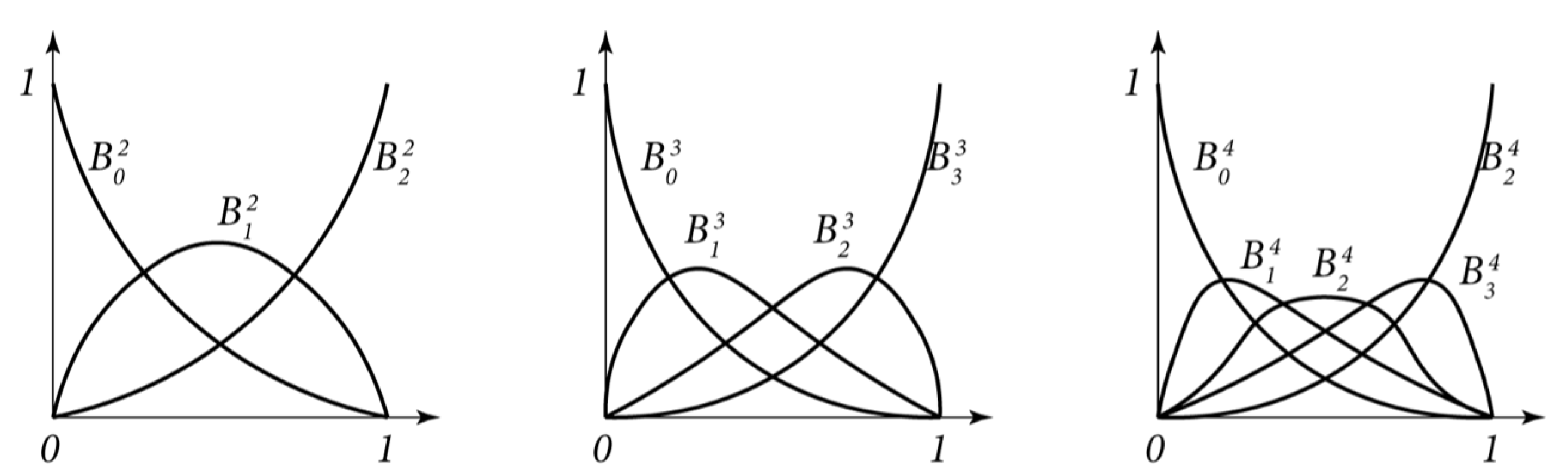
Waypoints (WPTs) are the points described by latitude and longitude values. In navigation, WPTs are connected by straight line segments. They are a natural way to determine a ship’s trajectory used by the navigator and sufficient for the helmsman when a ship is in the manual control mode. A human, due to experience and prediction ability, begins the turn before the WPT is passed and finishes it on the next trajectory segment. But for MASS this way of a trajectory description is infeasible and gives the overshoot in automatic control. Moreover, it requires the turn starting position definition in order to ensure turn finishing on the next trajectory segment.
Model Predictive Ship Control requires a reference trajectory. Providing reference as a set of WPTs leads to big prediction errors in their vicinity. So, there is a need to model a reference ship’s path with a curve instead of straight line segments. A simple, fast and reliable feasible path generator, which can predict a future trajectory consistent with dynamics of the ship, is required.
So, there is a need to connect a human-friendly description with feasible input for the trajectory tracking system. We propose Bézier curve path modeling, in which a curve order will be as low as possible. It simplifies and speeds up computations. We decided to use Bézier rational curves, because not every trajectory may be approximated by a Bézier polynomial curve. The only polynomial conic curve is a parabola, while ship’s circulation in the steady state is approximated by a circle. Moreover, the ship’s turn is an ellipse segment. Unfortunately, these curves are not accurately approximated by polynomial Bézier curves. The second reason why we decided to use rational Bézier curves is the ability to involve ship parameters in coefficients estimation. In our approach, we are able to take into account ship’s leeward tendency, velocities and dimensions. It was assumed that the maneuver is not trivial. A feasible path is modeled as composition of straight line motion, arc movement and straight line motion. Curve parametrization avoids setting control points based on optimization procedures and allows WPTs to become Bézeir curve control points.

2.2. Bézier Curves

We now briefly present the notion of de Casteljau algorithm and Bézier curves to provide some information about our main geometrical tool. Let n N , and let us select a finite sequence of n + 1 different points P 0 , , P n on a plane R 2 . Let l be a polygonal chain with vertices at P 0 , , P n . For any t [ 0 , 1 ] , let us divide every segment P i P i + 1 of l in the proportion t : 1 t . The resulting points we denote by P 0 1 , , P n 1 1 .
We repeat the described process as long as only one point P ( t ) is left, which is the point of our desired curve. The above described algorithm is called the Casteljau algorithm (see Figure 1), where the obtained points form the Bézeir curve P : [ 0 , 1 ] R 2 . The points P 0 , , P n are called the control points of P , while the polygonal chain l is called the Bézier chain or control chain
The Bézier curve P : [ 0 , 1 ] R 2 is a polynomial curve, that is, if P is described by n + 1 control points then its coordinates are described by some polynomials of the variable t of the degree not exceeding n. Moreover, P is contained in the convex hull of the control points P 0 , , P n , and P is invariant under any affine transformation of the plane R 2 .
Let us now consider the polynomials
B i n ( t ) = n i t i ( 1 t ) n i dla i = 0 , , n .
We also define B i n ( t ) = 0 for i < 0 and i > n . B i n ’s are called the Bernstein polynomials (see Figure 2).
One can observe [19] that the control points of a Bezier curve P determine the coefficients of this curve in the Bernstein polynomial basis, that is
P ( t ) = j = 0 n P j B j n ( t ) .
In further considerations it occurs that polynomial Bezier curves are flexible not enough for our purpose, so let us now dive into the notion of rational Bezier curves.
Let us choose points P 0 , , P n in the 3-dimensional space R 3 . Every curve P : [ 0 , 1 ] R 3 can be identified with a system of three functions X , Y , W : [ 0 , 1 ] R , that is
P ( t ) = ( X ( t ) , Y ( t ) , W ( t ) ) , t [ 0 , 1 ] .
Let E denote the 2-dimensional plane in R 3 defined by
E = { ( x , y , w ) R 3 | w = 1 } ,
and let p be the curve on E defined by
p ( t ) = ( X ( t ) W ( t ) , X ( t ) W ( t ) , 1 ) .
If we change the coordinate system translating the X and Y axes by the vector [ 0 , 0 , 1 ] , we can treat the curve p as a curve on a 2-dimensional plane, once again denoted by p , defined as
p ( t ) = ( X ( t ) W ( t ) , X ( t ) W ( t ) ) .
Thus, if X ( t ) , Y ( t ) , W ( t ) are polynomial functions, then the coordinates of p ( t ) are rational.
Now, any point p = ( x , y ) of R 2 (which we identify with E) can be described by a vector [ X , Y , W ] R 3 so that
x = X W and y = X W .
Note that this description is not unique. Multiplication of X , Y , W by a positive constant gives us the same point p .
Now, let p i = ( x i , y i ) , i = 0 , , n , be points on the 2-dimensional plane. Having weights W 0 , , W n , one can define points P i = ( W i x i , W i y i , W i ) R 3 , i = 0 , , n , so that P i defines the rational Bézeir curve with p i s as the control points via the procedure described above.
Let P 0 , , P n R 3 . Let us recall that every P j = ( X i , Y j , W j ) . These points define some polynomial Bézier curve in R 3 by
P ( t ) = j = 0 n P j B j n ( t ) .
Since the points P 0 , , P n define some points p i = ( X j W j , Y j W j ) , we can define a rational Bézier curve p : [ 0 , 1 ] R 2 by
p ( t ) = j = 0 n W j · p j B j n ( t ) j = 0 n W j · B j n ( t ) ,
Obviously [19], rational Bézier curves generalize the notion of a polynomial Bézier curves. Moreover, similarly to the polynomial ones, rational Bézier curves are invariant under any affine transformation.

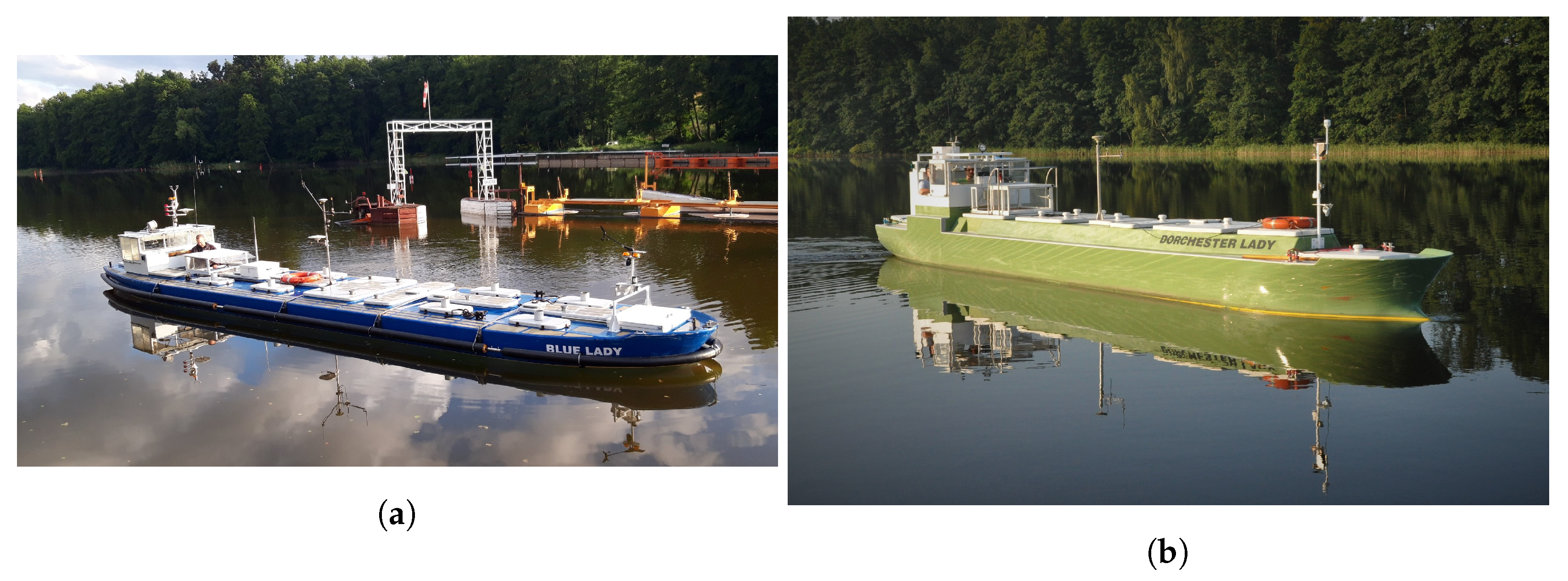
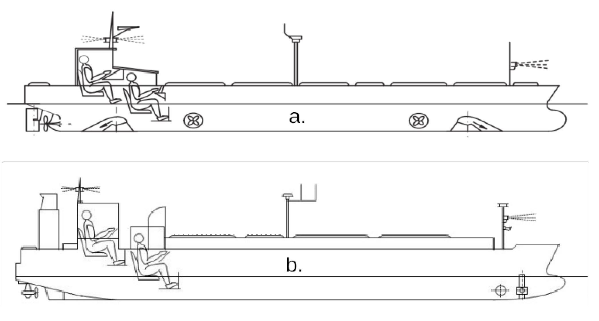
2.3. Test Bed—Training Ships

Bézier rational curve ship’s path modeling was performed based on the data obtained during training ships’ trajectory tracking. Training ships were used for the research due to difficulty in accessing merchant ships. All experiments were conducted in real time on the Silm lake, Poland, with the use of real floating training ships owned by the Foundation of Safety of Navigation and Environment Protection. In our research, two ships were used – the Liquid Natural Gas (LNG) Carrier “Dorchester Lady” and the Very Large Crude Carrier (VLCC) “Blue Lady” (see Figure 3). Their silhouettes are shown in Figure 4.
Both training ships are built in 1:24 scale in accordance to the geometric, kinematic and dynamic similarity laws, with no constant Reynolds numbers (due to the fact that ships and models move in the same environment). This leads to real merchant ships’ dynamics mapping. So, these training ships behave in the same way as full-size ships. Training ships dimensions are collected in Table 1.
The VLCC “Blue Lady” is equipped with the electric main engine, screw and rudder blade. Moreover, she has two pairs of tunnel and rotatable thrusters located at the bow and the stern, which are used only during maneuvers in the restricted waters. The LNG Carier “Dorchester Lady” has two electric azipods located astern combined with tunnel and rotatable thrusters located at the bow.

2.4. Method of Rational Bézier Curve Coefficient Determination
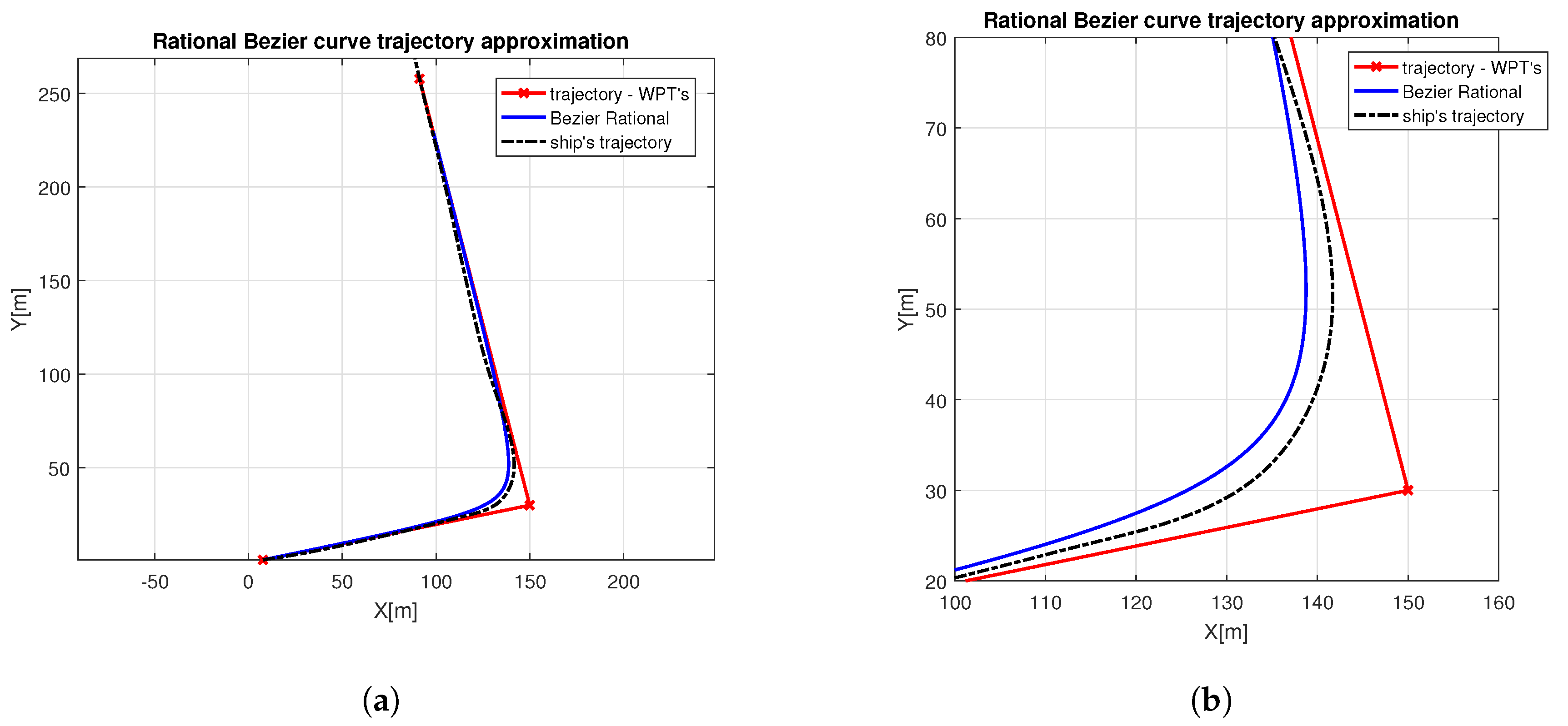
Modeling using the rational Bézier curve requires curve order, control points’ position and values of weights estimation. We started the approximation procedure with the square rational curve due to the standard way of arc and circle modeling. WPTs were chosen as the control points, because we wanted to use the standard ship’s trajectory description, which consists of a set of consecutive WPTs. The first set of weights was selected empirically. The preliminary test results, with the empirically chosen weights, showed that it is possible to model a feasible ship’s trajectory using the second order rational Bézier curve. The whole procedure was iterative one. Initial guess weights were modified and a modeled trajectory was compared with the one registered during the real-time lake trial. After the whole procedure, it turned out that it is possible to find the coefficients of the second order rational curve, enabling accurate modeling of ship trajectories. Modeling errors were less than ship’s breadth, which is acceptable for a control purpose.
The obtained preliminary results showed that there is no need for higher order curve usage due to ship trajectory modeling potential. Our motivation was to generalize the trajectory modeling method for all ship types. So we decided to find the relationship between values of rational Bézier curve coefficients and particular ship dimensions and motion parameters. We connected them according to the procedure described below.
Curve coefficients were estimated in an experimental way, knowing that the ship’s movement is affected by parameters such as: drift, longitudinal, transversal and angular velocities, displacement and length overall. Displacement and length overall are static parameters. Drift and all three velocities (longitudinal, transversal and angular) are dynamic ones, because they change during a trajectory tracking process and depend on one another. We expected that input and output rational curve coefficients depend on her coefficient on the arc. We also expected the quadratic or square root relationship between them due to the order of a selected rational Bézier curve.
Ship’s inertia and the turning radius depend on ship’s length and displacement. The ship’s movement method during her turn may be defined by the angular and drift path. The angular path is defined by
φ = | r | d t ,
where r denotes angular velocity, and describes ship’s angle of turn. Combined with the circulation radius R, it determines length of the path traveled by the ship in the longitudinal axis (in an arc) which is defined by
S φ = R φ .
S φ is used for ship’s position is modeled curve prediction. Its combination with the measured longitudinal speed allows determining the current position on the approximated trajectory and predicting future ship’s position. One can predict longitudinal ship’s speed based on the past and current values of angular and transversal velocities combined with the distance traveled along a curve or a straight line.
The drift path is defined by
S drift = | v | d t
and it determines length of the path traveled by the ship in the transversal axis due to centrifugal force.
The coefficient on arc ( W 2 ) depends on ship’s length, displacement, angular and drift path lengths. It is defined by
W 2 = L φ ( 1 c ) S drift ,
where: L—length overall, ∇—displacement, r—angular velocity, v—transversal velocity, c—dimensionless coefficient. The coefficient c value is a ratio of trajectory approaching time ( t a p p ) and the whole maneuver time ( t m )
c = t a p p t m .
Ship dynamics is independent of the performed motion and ship inertia does not change with changing angular velocity. So, input ( W 1 ) and output ( W 3 ) coefficients have the same value and they depend only on the coefficient on arc value. They are the inverse of a square root of the arc coefficient W 2 :
W 1 = W 3 = 1 W 2 .
It was proved by the computer simulations that these values give the best Bézier curve trajectory approximation results.
According to the methodology described above, ship’s path modeling is based on a set of known WPTs and requires two coefficient values calculation.

3. Results

This section presents the results of ship trajectory modeling with the use of Bézier rational curves. All, the presented trajectories, called “ship’s trajectory”, were registered during real time lake trials. The training ships were then in automatic control. For the VLCC “Blue Lady”, we referred to the papers of Rybczak and Tomera [20,21,22], where trajectory tracking performance was described in a very detailed way. We also use trajectories registered during the LNG “Dorchester Lady” path following described in [18].
Figure 5 and Figure 6 present the exemplary VLCC “Blue Lady” rational Bézier curve trajectories approximation. The red line connects WPTs and indicates a reference ship’s trajectory. The ship’s trajectory registered during automatic control trials is represented by the solid black line. In the first exemplary trial presented in Figure 5, the VLCC training ship turns 95 to the port side. The largest distance between real and modeled trajectories reaches 3.1 m. The ship turns closer to the middle WPT and her circulation radius is smaller than in the modeled curve. In the second exemplary trial shown in Figure 6 the VLCC training ship turns 45 to the starboard side. The biggest observed error in modeling reaches 4.0 m. Modeling errors are closely-coupled with the automatic control quality. Ship trajectory oscillations cause errors in coefficients’ computations. Moreover, when the ship moves on the outside of the reference trajectory the error increases due to the assumption made that the Bézier rational curve is inscribed between two straight lines defining a reference trajectory.
Figure 7, Figure 8 and Figure 9 present the LNG carrier training ship’s turns of 20 , 45 and 55 to the port, starboard and starboard sides respectively. In these Figures reference trajectories consisting of WPTs connected with straight lines, are marked by red lines. Black lines are used to present the real training ship’s trajectory. The rational Bézier curve modeled trajectory is presented as the solid blue line.
There are very small oscillations and errors in the LNG carrier training ship’s automatic trajectory tracking system. This leads to higher quality modeling using rational Bézier curves. The maximum deviations of the modeled curve from the real trajectory in three exemplary cases are respectively: 1.5 m, 1.3 m and 0.5 m for three exemplary trials. For the other measurements the maximum deviations values are between the whole and quarter ship’s breadth and their mean value is about half of the ship’s breadth.
Table 2 summarizes the research data for three exemplary trials. The VLCC training ship trajectory was modeled less accurately. Deviations of rational Bézier curve coefficients reach 14 % of the average value from all the experiments. In the case of the LNG carrier training ship their deviations do not exceed 10 % . The maximum observed error values, presented in Table 2, were computed as the maximum absolute distance between the modeled and real-time registered ship’s trajectory. These values are equal to the absolute error computed as a supremum. The ship was positioned along the modeled path with the use of S φ value. The maximum observed error in trajectory approximation for the VLCC ship reaches 4.0 m which is almost three times bigger than the absolute error in trajectory approximation for the LNG carrier. During the entire analyzed maneuver, the ship maneuvers for about 50 % of the time to reach a target trajectory, as indicated by the c coefficient values.

4. Discussion

Using WPTs as the curve control points allows integration a trajectory intuitive for the navigator with a path predicting model used as reference in the control system. Input weights parametrization is important, due to their time consuming optimization procedure avoidance. Moreover, we conducted the ship’s path modeling analysis based on the automatic trajectory tracking results for training ships.
It is possible to average rational Bézier curve coefficients W 1 , W 2 , W 3 for each ship. They are ship’s turn angle independent, but different for each vessel type and dimensions. The research results showed that, input ( W 1 ) and output ( W 2 ) coefficients have the same value which depends only on the on arc ( W 2 ) coefficient value. However, the on arc coefficient is parametrized in accordance with the adopted assumptions and depends on ship’s length, displacement, angular path, drift path and trajectory approaching time to the whole maneuver time ratio. This statement is crucial for future off-line coefficients estimation, for the real-time on-line trajectory prediction system. Off-line estimated coefficients, which are independent of WPTs position and ship’s angle of turn, may be used during curve line reference trajectory generation.
The proposed geometrical modeling tool is easy to use and implement in any MASS system. We incorporated ship maneuvering characteristics into the rational Bézier curve points computation algorithm using weight coefficients dependent on ship parameters. During future trajectory prediction, there is a need only to provide individual WPT coordinates in order to compute feasible reference. Moreover, there is no need to optimize a predicted trajectory, which may be directly applied as reference to any automatic ship control system. Curve trajectory usage, instead of a set of straight line segments, improves control quality by overshoots on turns and oscillations in trajectory tracking after turn elimination.
The presented tool may be applied to safe trajectory determination in MASS and the navigator’s decision support systems. This tool may also be used as a reference trajectory generator in all model-based and predictive control ship trajectory tracking automatic control systems. Having two or more MASS equipped with the Bézier curve based trajectory prediction system and making them exchange values of their coefficients and WPT coordinates, there is a possibility to identify whether there is a risk of collision near the WPT. In the conventional anti-collision scheme the ship is assumed to be moving along a straight line with a constant speed. During anti-collision maneuver computation only the present motion vectors are taken into account. Dynamic properties of the ships are not analyzed. So, this modeling tool may also be useful in MASS collision avoidance and during studies on convergence of trajectories and a possibility of collision during the UNREP maneuver.
We got much better results for the LNG carrier training ships due to better quality of her automatic control. There are less oscillations and overshoots in the registered trajectories. It leads to higher precision in c-coefficient estimation and therefore input weights of the rational Bézier curve are calculated with greater accuracy. The rational Bézier curve coefficients were computed with accuracy better than 10 % for the LNG carrier and 18 % for the VLCC. More accurate determination of the coefficients and their smaller standard deviation from the mean value leads to better trajectory mapping. It is a reason why we got better results for one of the training ships.

5. Conclusions

We have presented a mathematical modeling tool, which may be used for ship’s trajectory mapping. The proposed simple mathematical tool allows for ship’s path estimation and prediction on the basis of a set of WPTs. The problem of nonlinear reference based on the ship dynamics is addressed. The Bézier square rational curve is used to provide feasible reference for a particular autonomous ship. Curve parametrization method, using coefficients determined on the basis of the ship motion and dimension parameters, was presented. Relationships between the individual curve coefficients and the vessel parameters were indicated. It was proved that these coefficient values do not depend on the turning angle and have a similar value for a particular vessel, which allows for their off-line computation and usage in the on-line trajectory prediction system. This leads to computations simplification and fastening, crucial for the real operating MASS reference generation. The research carried out showed that there is a possibility to incorporate ship dynamics into reference trajectory generation algorithm and deliver feasible reference to any MASS controller.
The proposed methodology is very simple. Its application does not require prior collection of large amounts of the AIS data. It guarantees the ease of determining the parameters necessary to generate the coefficients for a specific vessel. It is only necessary to make a few turns to port and starboard side and compute the coefficient values according to the presented formulas. It is possible because the values of coefficients depend on the ship parameters, its speed, and not on the angle of turn. Future trajectory approximation is then fast and easy. It requires a small amount of the controller memory.
Our future work will relate to ship’s circulation modeling, path generator in model predictive controller involvement and our path approximation tool connected with longitudinal ship’s velocity and time in order to get a complete trajectory prediction system. It will make it possible in future to develop a reliable safe trajectory generation system, in which collisions with moving objects and obstacles may be avoided.

Author Contributions

Conceptualization, A.M. and S.W.; methodology, A.M. and S.W.; software, S.W.; validation, A.M.; formal analysis, A.M. and S.W.; investigation, A.M. and S.W.; resources, S.W.; data curation, A.M.; writing–original draft preparation, A.M. and S.W.; writing–review and editing, A.M.; visualization, A.M.; supervision, S.W.; project administration, S.W.; funding acquisition, A.M. and S.W. All authors have read and agreed to the published version of the manuscript.

Funding

This research was funded by UMG grant number WE/2020/PZ/03 and UJK grant number SMGR.RN.20.276.

Conflicts of Interest

The authors declare no conflict of interest.

References

  1. Plessen, M.M.G.; Bemporad, A. Reference trajectory planning under constraints and path tracking using linear time-varying model predictive control for agricultural machines. Biosyst. Eng. 2017, 153, 28–41. [Google Scholar] [CrossRef]
  2. Dixit, S.; Montanaro, U.; Fallah, S.; Dianati, M.; Oxtoby, D.; Mizutani, T.; Mouzakitis, A. Trajectory planning for autonomous high-speed overtaking using MPC with terminal set constraints. In Proceedings of the 2018 21st International Conference on Intelligent Transportation Systems (ITSC), Maui, HI, USA, 4–7 November 2018; pp. 1061–1068. [Google Scholar]
  3. Nolte, M.; Rose, M.; Stolte, T.; Maurer, M. Model predictive control based trajectory generation for autonomous vehicles—an architectural approach. In Proceedings of the 2017 IEEE Intelligent Vehicles Symposium (IV), Los Angeles, CA, USA, 11–14 June 2017; pp. 798–805. [Google Scholar]
  4. Xi, W.; Baras, J.S. MPC based motion control of car-like vehicle swarms. In Proceedings of the 2007 Mediterranean Conference on Control & Automation, Athens, Greece, 27–29 June 2007; pp. 1–6. [Google Scholar]
  5. Hu, Q.; Xie, J.; Wang, C. Dynamic path planning and trajectory tracking using MPC for satellite with collision avoidance. ISA Trans. 2019, 84, 128–141. [Google Scholar] [CrossRef] [PubMed]
  6. Shi, J.; Sun, D.; Qin, D.; Hu, M.; Kan, Y.; Ma, K.; Chen, R. Planning the trajectory of an autonomous wheel loader and tracking its trajectory via adaptive model predictive control. Robot. Auton. Syst. 2020, 131, 103570. [Google Scholar] [CrossRef]
  7. Cagienard, R.; Grieder, P.; Kerrigan, E.C.; Morari, M. Move blocking strategies in receding horizon control. J. Process Control 2007, 17, 563–570. [Google Scholar] [CrossRef] [Green Version]
  8. Huang, L.; Wen, Y.; Guo, W.; Zhu, X.; Zhou, C.; Zhang, F.; Zhu, M. Mobility pattern analysis of ship trajectories based on semantic transformation and topic model. Ocean Eng. 2020, 201, 107092. [Google Scholar] [CrossRef]
  9. Gao, M.; Shi, G.Y. Ship-handling behavior pattern recognition using AIS sub-trajectory clustering analysis based on the T-SNE and spectral clustering algorithms. Ocean Eng. 2020, 205, 106919. [Google Scholar] [CrossRef]
  10. Zhang, L.; Meng, Q.; Xiao, Z.; Fu, X. A novel ship trajectory reconstruction approach using AIS data. Ocean Eng. 2018, 159, 165–174. [Google Scholar] [CrossRef]
  11. Lazarowska, A. A new deterministic approach in a decision support system for ship’s trajectory planning. Expert Syst. Appl. 2017, 71, 469–478. [Google Scholar] [CrossRef]
  12. Wen, Y.; Sui, Z.; Zhou, C.; Xiao, C.; Chen, Q.; Han, D.; Zhang, Y. Automatic ship route design between two ports: A data-driven method. Appl. Ocean Res. 2020, 96, 102049. [Google Scholar] [CrossRef]
  13. Hassani, V.; Lande, S.V. Path planning for marine vehicles using Bezier curves. IFAC Pap. 2018, 51, 305–310. [Google Scholar] [CrossRef]
  14. Yang, G.J.; Choi, B.W. Smooth trajectory planning along Bezier curve for mobile robots with velocity constraints. Int. J. Control Autom. 2013, 6, 225–234. [Google Scholar]
  15. Choi, J.W.; Curry, R.; Elkaim, G. Path planning based on bézier curve for autonomous ground vehicles. In Proceedings of the Advances in Electrical and Electronics Engineering-IAENG Special Edition of the World Congress on Engineering and Computer Science 2008, San Francisco, CA, USA, 22–24 October 2008; pp. 158–166. [Google Scholar]
  16. Chen, L.; Wang, S.; Hu, H.; McDonald-Maier, K. Bézier curve based trajectory planning for an intelligent wheelchair to pass a doorway. In Proceedings of the 2012 UKACC International Conference on Control, Cardiff, UK, 3–5 September 2012; pp. 339–344. [Google Scholar]
  17. Yu, W.; Shuo, W.; Rui, W.; Min, T. Generation of temporal–spatial Bezier curve for simultaneous arrival of multiple unmanned vehicles. Inf. Sci. 2017, 418, 34–45. [Google Scholar] [CrossRef]
  18. Gierusz, W.; Miller, A. Ship Motion Control System for Replenishment Operation. In Applied Mechanics and Materials; Trans Tech Publ.: Zurich, Switzerland, 2016; pp. 214–222. [Google Scholar]
  19. Kiciak, P. Podstawy Modelowania Krzywych i Powierzchni: Zastosowania w Grafice Komputerowej; Wydawnictwa Naukowo-Techniczne/Wydawnictwo Naukowe PWN: Warszawa, Poland, 2019. [Google Scholar]
  20. Rybczak, M. Improvement of control precision for ship movement using a multidimensional controller. Automatika 2018, 59, 63–70. [Google Scholar] [CrossRef] [Green Version]
  21. Tomera, M. Hybrid real-time way-point controller for ships. In Proceedings of the 2016 21st International Conference on Methods and Models in Automation and Robotics (MMAR), Miedzyzdroje, Poland, 29 August–1 September 2016; pp. 630–635. [Google Scholar]
  22. Tomera, M. Sterowanie modelem fizycznym zbiornikowca wzdłuż zadanej trasy przejścia. Zeszyty Naukowe Wydziału Elektrotechniki i Automatyki Politechniki Gdańskiej 2016, 51, 201–208. [Google Scholar]
Figure 1. De Caslteljau algorithm.
Symmetry 12 01704 g001
Figure 2. Bernstein polynomials.
Symmetry 12 01704 g002
Figure 3. VLCC “Blue Lady” (a) and “Dorchester Lady” (b)—training ships.
Symmetry 12 01704 g003
Figure 4. VLCC “Blue Lady” (a) and “Dorchester Lady” (b)—training ships silhouettes.
Symmetry 12 01704 g004
Figure 5. Exemplary VLCC “Blue Lady” rational Bézier curve trajectory approximation at 90 turn to the port side (a) and trajectory enlarging near the middle WPT (b).
Symmetry 12 01704 g005
Figure 6. Exemplary VLCC “Blue Lady” rational Bézier curve trajectory approximation at 45 turn to the starboard side (a) and trajectory enlarging near the middle WPT (b).
Symmetry 12 01704 g006
Figure 7. Exemplary VLCC “Blue Lady” rational Bézier curve trajectory approximation at 20 turn to the port side (a) and trajectory enlarging near the middle WPT (b).
Symmetry 12 01704 g007
Figure 8. Exemplary VLCC “Blue Lady” rational Bézier curve trajectory approximation at 45 turn to the starboard side (a) and trajectory enlarging near the middle WPT (b).
Symmetry 12 01704 g008
Figure 9. Exemplary VLCC “Blue Lady” rational Bézier curve trajectory approximation at 55 turn to the starboard side (a) and trajectory enlarging near the middle WPT (b).
Symmetry 12 01704 g009
Table 1. Training ship dimensions.
VLCCLNG Carrier
“Blue Lady”“Dorchester Lady”
Length overall L [m]13.7811.33
Breadth B [m]2.381.80
Draft T [m]0.860.50
Displacement D [T]22.838.21
Max. speed u [kn]3.103.20
Table 2. Exemplary rational Bézier curves coefficients, dimensionless coefficient, angular and drift paths.
ex.max.cangulardrift W 2 W 1 , 3
error [m]coef. [–]path [m]path [m]coef. [–]coef. [–]
VLCC 13.10.65116.4627.993.650.52
VLCC 24.00.4673.9615.032.760.60
LNG 11.50.6164.7919.995.990.41
LNG 21.30.57103.1731.415.410.43
LNG 30.50.5098.1828.064.960.45
Publisher’s Note: MDPI stays neutral with regard to jurisdictional claims in published maps and institutional affiliations.

