Abstract
Heat-treated high-strength rebar has many advantages, such as high strength, superior ductility, high yield ratio, excellent welding and cold bending performance, which can effectively reduce the amount of rebar and improve the project quality. Although heat-treated high-strength rebar has been successfully applied in many fields of civil engineering, its application in tunnel engineering is just getting started. In this study, the on-site test of axisymmetric heat-treated high-strength lattice girders in rail tunnels and road tunnels was carried out. Comparative analysis of the performance of axisymmetric heat-treated high-strength lattice girders and original-design I20b steel rib was conducted. The test results show that the settlement of high-strength lattice girders is decreased by about 7%~30% compared with the test section of original-design I20b steel rib. The surrounding rock pressure is similar, but the stress of high-strength lattice girders is slightly higher than that of I20b steel rib. Due to the better binding ability of the lattice girders and the concrete, the ultimate bearing capacity of the ‘lattice girders and shotcrete’ is greater than that of the ‘I20b steel rib and shotcrete’. Moreover, the steel consumption of lattice girder is about 36% less than I20b steel rib, which shows significant economic and social benefits.
1. Introduction
With the rapid development of tunnels and underground engineering, China has gradually become the country with the largest scale and largest number of tunnels and underground projects, the most complex geological conditions and structural forms, and the fastest-growing construction technology in the world. However, the application of steel bars in tunnel and underground engineering construction in China is still dominated by ordinary steel bars. Compared with high-strength rebar in municipal engineering, building construction, and bridge projects, it is obviously in a lagging phase [1,2]. High-strength rebar is a new type of building material with high strength, good ductility, high yield ratio, low strain aging sensitivity, good welding and cold bending performance, etc. Compared with ordinary steel rebar, it can improve the quality of engineering and reduce the amount of steel used in the project, which corresponds the policy of energy saving and emission reduction in China [3,4]. Therefore, the application of high-strength rebar in tunnels and underground engineering will be the future development trend.
The support structure of tunnel and underground engineering is mainly divided into the wooden girders mainly used in mining tunnels [5,6], and the combinations of ‘grid arches + sprayed concrete’ or ‘steel arches + sprayed concrete’ mainly used in road and rail tunnels [7,8,9,10,11]. At present, there is more relative research on the applicability of lattice girder and steel arch frame. The lattice girder has stronger adhesion to shotcrete and better economics, whereas steel arch frame with a large rigidity can quickly provide support capacity and is mostly used for soft fractured surrounding rock. High-strength lattice girder is the lattice girder in which rebar is replaced by high-strength rebar in order to improve the support performance. Nowadays, relevant research of high-strength lattice girder in China is still in the start-up stage. Yu [4] carried out laboratory loading tests on high-strength reinforced concrete composite support and concluded that high-strength steel significantly improved the ultimate bearing capacity and ultimate deformation capacity. In other countries, research was focused on the structural style of the grid arch [12,13,14,15,16]. However, none of the above studies involves the influence of high-strength reinforcement on the mechanical properties of steel arch concrete composite support structure, which restricts the technical progress of tunnel engineering.
With the gradual increase of the span of tunnel constructions and the complex and varied formation conditions, the adaptability of high-strength steel grids to tunnels still needs to be verified. In this paper, the in-situ test results of several tunnel engineering projects are compared and the feasibility of replacing the I20b-shape steel arch frame with high-strength lattice girder in large-span tunnels is investigated.
2. Performance of Heat-Treated High-Strength Rebar and Steel Arch Structure
2.1. Mechanical Property of Heat-Treated High-Strength Rebar
At present, high-strength rebar generally has a yield strength of 400–500 MPa. Heat-treated high-strength rebar is made by adjusting the hot-rolled rebar of HRB400 through the quenching and tempering process of heat-treatment to improve the strength and plastic toughness of the rebar, so that the yield strength of the rebar can reach over 600 MPa. Considering the bearing capacity requirements of the tunnel primary support, the main rebar of the high-strength lattice girder chooses the crescent ribbed rebar with a yield strength of 600 MPa, and stirrup and stiffeners choose plain round bars with a yield strength of 900 MPa. The structure is shown in Figure 1 and the mechanical properties in Table 1. Heat-treated high-strength rebar not only improves the yield strength but also meets the requirements of strength ratio and elongation. Therefore, for the primary support to withstand large surrounding rock pressure or local stress concentration, the rebar allows a certain plastic deformation and can provide sufficient support strength to ensure the safety of the support structure.
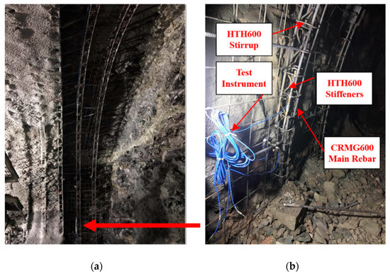
Figure 1.
High-strength lattice girders. (a) Display of overall lattice girders. (b) Display of partial lattice girders.

Table 1.
Mechanical properties of heat-treated high-strength steel reinforcement.
2.2. Structural Characteristics of Steel Arch Frame
Steel arch frame includes section steel arch frame and lattice girder. Section steel arch frame has a good section, such as H-shape, I-shape, or U-shape, which is always used in complex broken surrounding rock conditions. It can provide a certain supporting reaction force in a short time and independent bearing capacity after tunnel excavation. Lattice girder has the characteristics of equal strength, equal stiffness, and equal stability in two directions on the cross-section and has considerable flexibility. The application of high-strength lattice girder not only retains the support flexibility of the original lattice girder but also improves the ultimate bearing capacity of the support, so that high-strength lattice girder has the feasibility of application in complex fractured formations.
2.2.1. Support Stiffness of Steel Arch Frame
According to Equation (1) of structural bending stiffness, the bending stiffness of the arch structure is related to the elastic modulus of material and the cross-section of the arch structure to the moment of inertia of the curved neutral axis.
where E is the elastic modulus of the steel material, I is the moment of inertia of the structural cross section facing the curved neutral axis.
Heat-treated high-strength rebar only changes the heat-treatment method of quenching and tempering during the processing, and the material elastic modulus E is not much different from ordinary rebar. Table 2 shows the elastic modulus of heat-treated high-strength rebar and ordinary rebar. High-strength lattice girder and ordinary lattice girder adopt a four-legged structure, and the cross-section moment of inertia is also same. According to this, the bending rigidity of the high-strength lattice girder is similar to that of the ordinary lattice girder. The shape of the section steel arch frame is mostly H-shape and I-shape, and the moment of inertia is larger than lattice girder. According to Equation (1), the bending rigidity of I20b steel arch frame is about 56% higher than that of lattice girder. Therefore, the bending rigidity of high strength lattice girder + shotcrete is less than section steel arch frame + shotcrete [17,18,19].
Table 2.
Elastic modulus statistics of different steel reinforcement types.
2.2.2. Cohesiveness between Steel Arch Frame and Shotcrete
The form of high-strength lattice girder makes it more fully combine with shotcrete, the structure does not easily form cavities, and the primary support integrity is stronger. Section steel arches frame can provide larger supporting stiffness, but because of the existence of the flange plate, the back of the steel arch frame and the joint position form cavities, which directly affect the overall mechanical performance of a primary support—it is prone to groundwater seepage in the water-producing environment. After the combination of high-strength lattice girder and shotcrete, the supporting performance of “first soft then rigid” is formed. As the strength of shotcrete increases, the supporting structure stiffness also gradually increases, so the bearing capacity gradually increases [20]. However, the contact surface between the section steel arch frame and the surrounding rock is difficult to fill compactly with shotcrete, which leads to the uncoordinated deformation of the primary support; the cracking and falling phenomenon between the shotcrete and section steel arch frame can easily occur. In general, the high-strength lattice girder and shotcrete bond better.
2.2.3. Processing, Transportation, and Installation of Steel Arch Frame
The processing technology of the high-strength lattice girder includes the cutting and bending of the main rebar and stirrup, the pressing and bending of the stiffener, the welding of the lattice girders, and the welding of the connecting plate. But the processing of section steel arch frame can be completed by bending the section steel and welding the junction plate. In contrast, machining the lattice girder is more cumbersome. However, the steel consumption of high-strength lattice girder is obviously less than that of the section steel arch frame, so both the material cost and construction efficiency have advantages. Table 3 shows the weight statistics of standard section steel arch frame and high-strength lattice girder per meter. It can be seen that the weight of the high-strength lattice girder is about 82% of that of the I18 steel arch frame, 64% of that of I20b, and 54% of that of I22a. Therefore, high-strength lattice girder can save a large amount of steel and improve the construction efficiency of artificial support, so it has good social and economic benefits.
Table 3.
Statistics of the steel arch frame weight per meter.
3. Field Test of Heat-Treated High-Strength Lattice Girder
The laboratory loading test of heat-treated high-strength lattice girders is not enough to show its adaptability in real engineering. Therefore, field comparative tests of heat-treated high-strength lattice girders and section steel arch frame were carried out in several large-span tunnel projects that are under construction. The test items included tunnel crown settlement and horizontal convergence deformation, surrounding rock pressure, steel arch frame stress, etc. The relevant conditions of the engineering test section are shown in Table 4.
Table 4.
Test project of high-strength lattice girder.
In the test section, the main ribs, hoop ribs, and splayed ribs of the high-strength steel grid arch frame were made of heat-treated high-strength steel bars of Φ 22, Φ 10, and Φ 12, respectively. The properties of the steel bars are shown in Table 5. The test section was an I20b-shaped steel arch frame made of Q235 steel having a yield strength of 235 MPa. The measure point layout of the test section is shown in Figure 2. In Figure 2a, GD1 is the measure point of tunnel crown settlement and SL1 and SL2 are horizontal convergence measure lines. In Figure 2b, TY1–TY8 are the measure points of surrounding rock pressure. In Figure 2c, WG1–WG8 are the outer measure points of steel arch stress and NG1–NG8 are the inner measure points of steel arch. There are eight measure points of the surrounding rock pressure and steel arch stress for each section in the two-lane railway tunnel and the two-lane highway tunnel, while there are five measure points for each section in the three-lane highway tunnel. The test section of two-lane highway tunnel was conducted in winter, the test sections of three-lane highway tunnel was conducted in summer, and the test section of two-track railway tunnel was conducted in spring, respectively. Moreover, all the three test sections were more than 500 m away from the mouth of the tunnel and the air temperature had little influence on the stress of surrounding rocks. The influence of season on the test results is ignored in this paper.
Table 5.
The property of high-strength lattice girders.
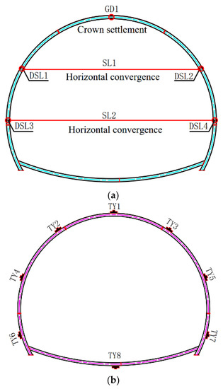
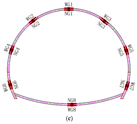
Figure 2.
The location of measure points. (a) Displacement measure points. (b) Surrounding rock pressure measure points. (c) Steel stress measure points.
4. Results and Analysis
4.1. Settlement and Convergence
Table 6 shows the average values of settlement and convergent of high-strength lattice girder and I20b-shape steel arch frame in each test tunnel. Figure 3 and Figure 4 are, respectively, typical sections time-history curves of crown settlement and horizontal convergence for each tunnel.
Table 6.
Average deformation of each tunnel test section.
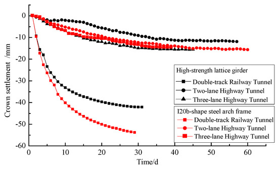
Figure 3.
Time-history curves of crown settlement for each tunnel’s test section.
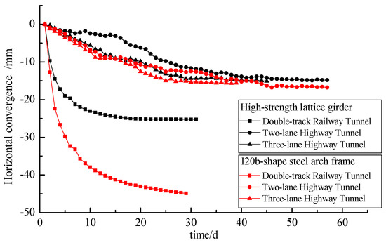
Figure 4.
Time-history curves of horizontal convergence settlement for each tunnel’s test section.
Comparisons of high-strength lattice girder and I20b-shape steel arch frame test section show that the crown settlement was reduced by 7%~26% and the maximum decrease was 7.4 mm. The horizontal convergence of the high-strength lattice girders test section was reduced by 12%~30% compared with that of the I20b-type steel test section and the maximum decrease was 10.2 mm. The distribution rule of the crown settlement and horizontal convergence of the high-strength lattice girders test section was basically the same as that of the I20b-shape steel arch frame test section. The difference value of crown settlement and horizontal convergence was −1.0~11.8 mm, and the difference value of I20b-shape steel arch frame test section was −0.8~9.0 mm. Both kinds of steel arch frame show that the settlement of the vault was close to horizontal convergence. The deformation development rule of high-strength lattice girders and I20b-type steel indicates that the early speed was faster and the deformation was stable after the steel arch frame was enclosing. In other words, the main reason was that the heat-treated high-strength lattice girders with the same section had relatively large stiffness compared to that of I20b-shape steel arch frame.
4.2. Surrounding Rock Pressure
Figure 5, Figure 6 and Figure 7 are the time-history curves and envelope diagram of surrounding rock pressure maximum value for the high-strength lattice girder test section of the double-track railway tunnel, the double-lane highway tunnel, and the three-lane highway tunnel, respectively. It can be seen that the surrounding rock pressure increased rapidly in the initial stage of tunnel excavation, while the strength of shotcrete was relatively low, and the steel arch frame provided the main support resistance. With the increase of shotcrete strength, the support strength of steel arch frame and shotcrete had increased, and the stress releasing rate of surrounding rock had decreased, until the invert was enclosing for a period of time, the surrounding rock pressure tended to be stable.
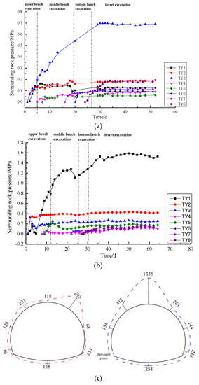
Figure 5.
Surrounding rock pressure distribution of double-track railway tunnel. (a) Time-history curve of surrounding rock pressure of high strength lattice girder. (b) Time-history curve of surrounding rock pressure of I20b steel arch. (c) Envelope diagram of surrounding rock pressure (red line for high strength lattice girder and blue line for I20b steel arch) (unit: kPa).
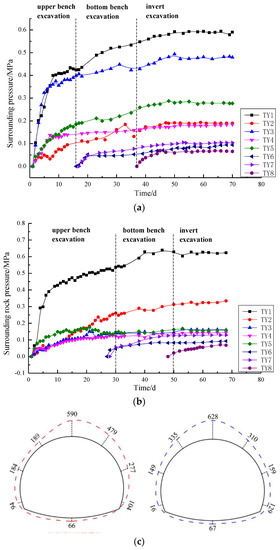
Figure 6.
Surrounding rock pressure distribution of double-lane highway tunnel. (a) Time-history curve of surrounding rock pressure of high strength lattice girder. (b) Time-history curve of surrounding rock pressure of I20b steel arch. (c) Envelope diagram of surrounding rock pressure (red line for high strength lattice girder and blue line for I20b steel arch) (unit: kPa).
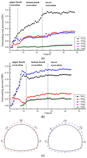
Figure 7.
Surrounding rock pressure distribution of three-lane highway tunnel. (a) Time-history curve of surrounding rock pressure of high strength lattice girder. (b) Time-history curve of surrounding rock pressure of I20b steel arch. (c) Envelope diagram of surrounding rock pressure (red line for high strength lattice girder and blue line for I20b steel arch) (unit: kPa).
The surrounding rock pressure in the high-strength lattice girders test section was irregular, the scale of double-track railway tunnel was 91–693 kPa, the double-lane highway tunnel was 66–590 kPa, and the three-lane highway tunnel was 16–282 kPa. The surrounding rock pressure of the I20b-shape steel arch frame was irregular, the scale of double-track railway tunnel was 154–1355 kPa, the double-lane highway tunnel was 67–628 kPa, and the three-lane highway tunnel was 52–235 kPa. The surrounding rock pressure of the two supporting test sections was larger at the arch part, and the maximum value was at the crown. On the whole, the surrounding rock pressures of the two supporting forms were almost equal to each other.
4.3. Stress of Steel Arch
Figure 8 shows the inside and outside maximum stress envelope diagram of each measure point for two kinds of steel arch frames. The red dashed lines in the figure represent the high-strength lattice girder, and the blue solid lines represent the I20b-shape steel arch frame. The negative sign indicates compression.
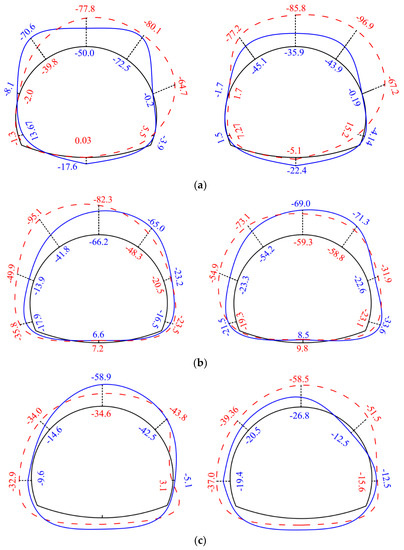
Figure 8.
The stress envelope diagram of high-strength lattice girder (red dashed line) and I20b steel-arch (blue solid line) (unit: MPa). (a) Double-track railway tunnel—inside and outside. (b) Double-lane highway tunnel—inside and outside. (c) Three-lane highway tunnel.
Most of the inside and outside measure points of the high-strength lattice girder element and I20b steel arch frame were under pressure, and a few of the measuring points were under tension and the value was small. The stress difference between the inside and the outside of the high-strength lattice girder was −23.0~37.4 MPa, the average difference was about 4.4 MPa. On the whole, the stress on the outside was bigger than that on the inside, and the stress above the arch was generally much bigger, the average stress of arch part was −63.1 MPa, the average stress of sidewall was −22.3 MPa, and the average stress of invert was 3.0 MPa. The stress difference between the inside and the outside of the I20b steel arch frame was −32.1~17.1 MPa, the average difference was about −2.9 MPa. The overall performance shows that the stress on the outside was bigger than that on the inside and the stress above the arch was also much bigger, the average stress of the arch part was −47.9 MPa, the average stress of the sidewall was −11.1 MPa, and the average stress of the invert was −6.2 MPa. The average stress of the high-strength lattice girder was −27.5 MPa, the average stress of the I20b steel arch frame was −21.7 MPa. The steel stress of the high-strength lattice girder was slightly higher, but stress distribution was relatively uniform.
5. Conclusions
Through the on-site comparison test study of heat-treated high-strength steel grid arch frame and steel arch frame, the main conclusions are as follows:
- (1)
- Heat-treated high-strength rebar has many advantages such as high strength, superior ductility, high yield ratio, excellent welding and cold bending performance, which can effectively reduce the amount of steel bars used in the project. The combination effect of the grille and the sprayed concrete is good, and the construction is convenient. It is not easy to form a void behind the initial support, which makes it easy to ensure the quality of the project.
- (2)
- The deformation monitoring data of the test section show that the crown settlement of the high-strength lattice girder is about 7%~26% smaller than that of the I20b steel arch frame, and the horizontal convergence of high-strength lattice girder is about 12%~30% smaller than that of I20b steel arch frame. The deformation law for both of them is same. In the early stage, the deformation increased rapidly, and it became stable after the invert was enclosing. The main reason for this is that the heat-treated high-strength lattice girders with the same section have relatively large stiffness compared to that of the I20b-shape steel arch frame.
- (3)
- The surrounding rock pressure and distribution of the high-strength steel grid arch section are basically the same as that of the I20b steel arch section, and the surrounding rock pressure of the dome is relatively large. Although the stress of the high-strength steel grid is slightly higher than that of the I20b steel, the stress distribution of the high-strength steel grid is more uniform.
- (4)
- Compared with the I20b steel arch frame, the high-strength lattice girder has more advantages. The main rebar for high-strength lattice girder is Φ 22, the weight per linear meter of which is 64% of that of the I20b steel arch frame, therefore, the high-strength lattice girder will reduce about 36% of the steel consumption, which has remarkable social and economic benefits and popularizing value.
Author Contributions
Z.T. and K.H. conceived of the idea of an experimental study on the application of heat-treated high-strength lattice girder in tunnel engineering. Z.T. conducted the field experiments and processed the experimental data.
Funding
The authors acknowledge the financial support provided by the National Natural Science Foundation of China (Grant No. 51678034).
Conflicts of Interest
The authors declare no conflict of interest.
References
- Wang, H.L. Chinese architecture will enter into the era of high-strength rebar. Constr. Architect. 2011, 19, 6–11. (In Chinese) [Google Scholar]
- Gao, C.; Lin, H.; Xu, S.Q. Economic analysis of high-strength bars in railway bridge engineering application. Railw. Stand. Des. 2018, 62, 59–63. (In Chinese) [Google Scholar]
- Du, M.M. Comment on the application of high-strength rebar in concrete structures. Concrete 2012, 9, 121–125. (In Chinese) [Google Scholar]
- Yu, F.C.; Zhang, D.L.; Fang, Q. Experimental study on characteristics of composite support with high-strength reinforcing lattice girders embedded in concrete. China Civ. Eng. J. 2015, 48, 104–111. (In Chinese) [Google Scholar]
- Coro, A.; Abasolo, M.; Aguirrebeitia, J.; López de Lacalle, L.N. Inspection scheduling based on reliability updating of gas turbine welded structures. Adv. Mech. Eng. 2019, 11, 1–20. [Google Scholar] [CrossRef]
- López de Lacalle, L.N.; Rodríguez, A.; Fernández-Valdivieso, A.; López-Blanco, R.; Fernández, J.; Azkona, I. On the cutting of wood for joinery applications. In Proceedings of the Institution of Mechanical Engineers Part B Journal of Engineering Manufacture, Bilbao, Spain, 20 October 2013. [Google Scholar]
- Guan, B.S. Tunneling by mining method: Lecture IV: Steel arch. Tunn. Constr. 2016, 36, 123–130. (In Chinese) [Google Scholar]
- Qu, H.F.; Zhu, H.H.; Huang, C.Z. Study on selection of section-steel and grid-steel in primary support system of tunnel. Chin. J. Undergr. Space Eng. 2005, 3, 258–262. [Google Scholar]
- Tan, Z.S.; Yu, Y.; Wang, M.N. Comparative tests on section steel and steel grid for loess tunnels with large section. Chin. J. Geotech. Eng. 2009, 31, 628–633. [Google Scholar]
- Chen, Z.X.; Hu, B.W.; Li, X.Z. Study on effect of steel framework in tunnel preliminary bracing. Constr. Technol. 2012, 41, 29–31. [Google Scholar]
- Li, H.Q.; Yang, C.Y.; Xu, M.X. Assessment on safety of lattice girder reinforced shotcrete support for tunnels. Chin. J. Rock Mech. Eng. 2009, 28, 3903–3908. [Google Scholar]
- Komselis, C.; Blayney, N.; Hindle, D. The use of lattice girders in the construction of tunnels. Masterbuilder 2012, 14, 88–94. [Google Scholar]
- Kim, S.; Han, T.H.; Baek, J.S. Evaluation of the structural performance of tetragonal lattice girders. Int. J. Steel Struct. 2013, 13, 31–47. [Google Scholar] [CrossRef]
- Nomikos, P.P.; Sofianos, A.I.; Sakkas, K.M. Nonlinear simulation of lattice girder segment tests. Tunn. Undergr. Space Technol. 2013, 38, 180–188. [Google Scholar] [CrossRef]
- Baumann, T.; Betzle, M. Investigation of the performance of lattice girders in tunnelling. Rock Mech. Rock Eng. 1984, 17, 67–81. [Google Scholar] [CrossRef]
- Oreste, P.P. Analysis of structural interaction in tunnels using the convergence-confinement approach. Tunn. Undergr. Space Technol. 2003, 18, 347–363. [Google Scholar] [CrossRef]
- Ding, Y.Z.; Tan, Z.S.; Ma, D.; Fan, M.G.; Huang, H.H. Study on support effect of high-strength steel grille in tunnel with IV grade surrounding rock. China Civ. Eng. J. 2017, 50, 98–103. [Google Scholar]
- Ma, D.; Tan, Z.S.; Ding, Y.Z.; Dong, B.L.; Huang, H.H. Study on support effect of high-strength steel grille in tunnel with V grade surrounding rock. China Civ. Eng. J. 2017, 50, 14–20. [Google Scholar]
- Zhang, F.P.; Wang, X.L.; Liu, Y.M. Effect of heat treatment on microstructure and property of high strength steel bar. Hot Work. Technol. 2014, 43, 169–173. [Google Scholar]
- Wang, M.S. China Tunnel and Underground Engineering Construction Technology; China Communication Press: Beijing, China, 2010. [Google Scholar]
© 2019 by the authors. Licensee MDPI, Basel, Switzerland. This article is an open access article distributed under the terms and conditions of the Creative Commons Attribution (CC BY) license (http://creativecommons.org/licenses/by/4.0/).