Abstract
Optimal design and singularity analysis are two important aspects of mechanism design, and they are discussed within a spatial parallel manipulator in this work. Resorting to matrix transformation, the parametric kinematic model is established, upon which the inverse position and Jacobian are analyzed. As for optimal design, dexterity and payload indices are taken into consideration. From the simulation results, two optimal configurations are obtained, namely, the star-shaped one and the T-shaped one, and they respectively own the best payload performance and the best dexterity performance. Moreover, the concept of shape singularity is introduced and generalized, which is a special type of singularity that will lead to the singularity in all configurations. The shape singularity of the proposed manipulator is indicated by dexterity index and identified by screw theory. A case study is presented to demonstrate the implication of the shape singularity. Both optimal and singular configurations are useful, and new devices can thus be envisaged for this type of application.
1. Introduction
Parallel manipulators (PMs) are closed-loop mechanisms modeled as a set of serial kinematic chains connected in parallel to two rigid bodies, namely, the mobile platform (MP) and the base platform. Compared with conventional serial manipulators, PMs exhibit many favorable advantages, such as higher stiffness, smaller mobile mass, larger load-weight ratio, better orientation precision, and higher speed capability. On the other hand, PMs also suffer from some shortcomings, such as complex forward position problems, relatively small workspaces, limited manipulability and coupled dynamics [1,2].
In order to overcome the drawbacks above, PMs with fewer than six degrees of freedom (DOF) are considered [3]. For examples, Rezaei et al. [4] presented a 3-PSP (P, R, U and S represent prismatic, revolute, universal and spherical joints, and an underlined letter indicates an actuator.) robot with symmetric geometry, and the forward position problem has a unique solution. Zhao et al. [5] investigated the forward kinematics of the Gough-Stewart manipulator with natural coordinates. Bai et al. [6,7] proposed a U-shape 3-PPR planar PM with the purpose of maximizing the workspace. Tsai and Joshi [3] had undertaken a workspace optimization that considered the quality of the workspace of a spatial 3-UPU PM. Stock and Miller [8] focused on the optimal kinematic design of a linear Delta robot, aiming to reach a compromise between manipulability and workspace size. Xu and Li [9] converted the original 3-PRC translational PM into a non-overconstrained one in order to solve the movability problem. Liu et al. [10] studied a new family of spatial 3-DOF fully PMs, which can exhibit high rotational capability.
With the purpose of identifying the nature of the interdependence of the pose parameters and the geometric significance, three symmetric zero-torsion PMs were considered in Reference [11], among which a spatial 3-PPS PM was introduced, while the closed-form solution to the direct kinematics was obtained. Singularity analysis of the 3-PPS PM was presented in Reference [12], with the consideration of the size of the workspace. A similar 3-PPS PM was reported in Reference [13], where the instantaneous mobility and constraint were analyzed. The 3-PPS PM was also proposed for the development of a dexterous 3-DOF force-controlled end-effector module which was available in Reference [14]. Moreover, the 3-PPS PM was chosen as a suitable candidate for nano-alignment applications with a research prototype developed in References [15,16]. The position and workspace analysis and optimal design of a 3-PPS were provided in Reference [17]. One can notice that the mechanisms mentioned above are only a special type of the 3-PPS PMs, which did not take the shape parameters into consideration.
One of the objectives of this work is to take shape parameters into consideration for optimal design. It is found that most manipulators studied are assumed as having a fixed shape of the platforms, while cases with different shapes of the platforms are rarely considered. It is thus desirable to study what will happen with a variety of shapes of the platforms. As for the generalized 3-PPS PM with shape parameters, two optimal configurations are obtained based on the performance evaluation.
Another objective of this work is to analyze the shape singularity of the 3-PPS PM. The shape singularity of the proposed manipulator is indicated by dexterity index and identified by screw theory. As reported in Reference [18], the shape singularity was found numerically within a planar PMs, while it is generalized from planar PMs to spatial PMs in this work.
The last objective is to explore how to utilize shape singularity in a novel mechanism design. While most singularity analyses were carried out with the purpose to identify the singular configurations and to eliminate singularity from the perspective of manipulator design and control, it would be of great significance if a singularity analysis could inspire novel mechanism design.
The rest of this paper is organized as follows. Section 2 explains the basic theory and background knowledge. Section 3 contains the kinematics analysis of the considered spatial 3-PPS PM. Optimal design and analysis of shape singularity are developed in Section 4. Discussion and conclusions are presented in the final section.
2. Materials and Methods
In the design process, dexterity, payload and compliance capability are very important for a machine, and these criterions are considered for the proposed 3-PPS PM. In terms of the optimal design of the proposed mechanism, two performance indices are considered, namely, dexterity and payload index. Moreover, the compliance index is applied to evaluate the compliance quality of shape singularity.
2.1. Dexterity Index
Dexterity index is an important performance index for mechanism design, which is defined as the mechanism’s ability to change the pose arbitrarily, and it can be expressed in terms of condition number [19]. For a Jacobian matrix J of full rank, the corresponding condition number can be expressed as:
The value of condition number will range from one to infinity, without an upper bound. So the reciprocal of the condition number called a local conditioning index (LCI) is used more commonly.
LCI is pose-dependent, which means it is a local performance. In order to evaluate the global dexterity behavior of a mechanism over the entire workspace, the global conditioning index (GCI) is defined as:
where W represents the entire workspace. Since the shape of the workspace is complex, it is not easy to obtain a closed form for the GCI, so the GCI is normally calculated numerically.
where NW is equal to the number of the points uniformly distributed over the workspace. The larger the GCI is, the better the global dexterity performance of the mechanism is.
2.2. Payload Index
Payload capability is another important performance of PMs, which is applied to measure the manipulator’s ability to stand the external force acted on the MP.
Referring to the virtual work principle [20], the relationship between virtual displacement δq of the joints and the virtual displacement δx of the MP can be expressed as:
where τ is the external force, f is the driving force.
On the other hand, the relationship between δq and δx can be expressed in another form as:
which leads to:
Let f be a unit vector, the extremum of the norm of τ can be obtained as:
where λpi are the eigenvalues of matrix JJT, and Pmin is the minimum external force that the mechanism can stand.
In order to measure the payload capability of a mechanism over the entire workspace, the global payload index (GPI) is defined as:
The larger the GPI is, the better the payload performance of the mechanism is.
2.3. Compliance Index
As reported in [20,21], the stiffness matrix of PMs can be written as:
where Kp is a matrix describing the stiffness of the platform mounted with elastic elements. For the 3-DOF 3-PPS PM, Kp = diag(k1,k2,k3).
The deflection of the MP which corresponds to the external force is defined as:
It can be found that the extremum eigenvalue λsi of the matrix K−TK−1 is the limit value of ||ΔX||2. Let k1= k2= k3=1 and ||f||=1, the maximum deformations can be expressed as:
In order to evaluate the stiffness performance of a mechanism over the workspace, the global stiffness index (GSI) is defined as:
For a mechanism, the reciprocal of the stiffness is referred to as compliance, so the larger the GSI is, the better the compliance performance of the mechanism is.
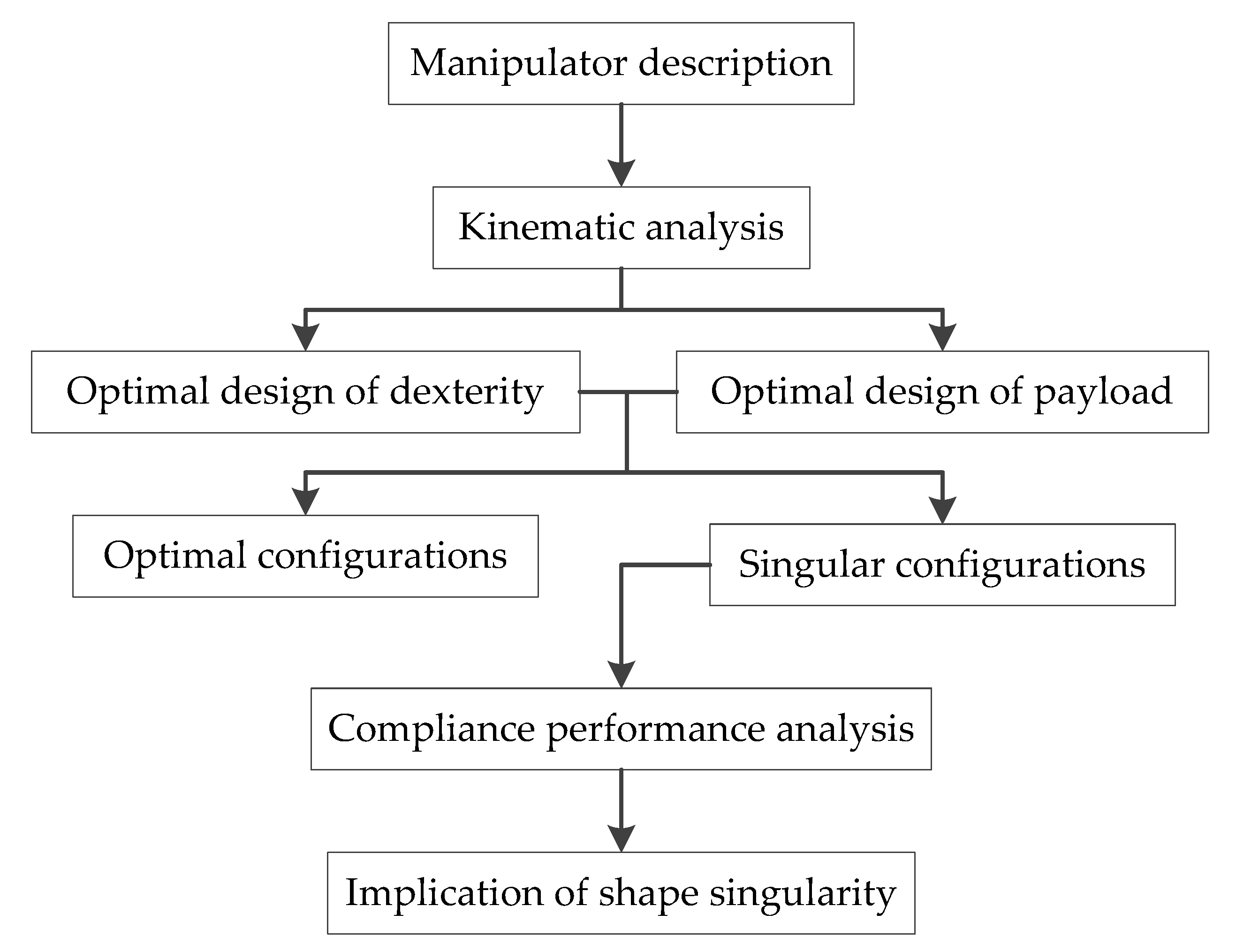
With the selected performance indices, the concrete flow for optimal design and shape singularity analysis is as shown in Figure 1. Firstly, the inverse position and Jacobian are analyzed based on the parametric kinematic model. Then, dexterity and payload performance are evaluated for optimal design. Moreover, shape singularity is identified by screw theory with its compliance performance analyzed. At last, the implication of shape singularity is discussed.
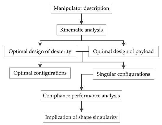
Figure 1.
Flowchart for optimal design and shape singularity analysis.
3. Structure Description and Kinematic Analysis
The considered spatial 3-PPS PM is shown in Figure 2, and it consists of three identical PPS kinematic limbs, all connecting the MP to the base. The first prismatic joint in each limb is chosen as the active joint, and the axes of the passive prismatic joints gi are perpendicular to the axes of the active prismatic joints fi. Moreover, the shape of the base is parameterized, namely, the orientation of axes of the active prismatic joints is defined by pan angle δ (0° ≤ δ ≤ 90°) and tilt angle γ (0° ≤ γ ≤ 90°). On the other hand, both the MP and base platform are modeled as equilateral triangles, with side lengths a and b, respectively.
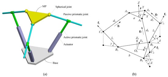
Figure 2.
The 3-PPS parallel manipulator (PM): (a) The 3D model and (b) the kinematic description.
3.1. Pose of the MP
The proposed 3-PPS PM is a 3-DOF mechanism, which means the pose (position and orientation) of the MP can be described by three independent kinematic parameters. For general 3-PPS PM (δ ≠ 0°), (x, y, z, ψ, θ, ϕ) is the pose of the MP with respect to the global frame. Here, z, ψ, and θ are chosen as the independent kinematic parameters, so the first step is to determine the pose of the MP with the three independent kinematic parameters.
As depicted in Figure 2b, global frame {O0} is fixed on the base, with the origin coinciding with the centroid of the base, where Y0-axis is pointed along the direction of B2B3, Z0–axis is perpendicular to the base. Local frame {O} is attached to the centroid of the MP in a similar way.
By the given pose of the MP, the position vector of point Ai in the global frame results in:
where is the position vector of point Ai in the local frame, is the rotation matrix, is the position vector.
Projection of Ai in the base plane satisfies following equations:
where , , and the position vector of point Bi in the global frame can be written as:
By virtue of Equations (16)–(18), the three unknown pose parameters ϕ, x, and y can be determined.
with
where s and c stand for sine and cosine.
Note that when δ = 90° we have
Until now, the pose of the MP of general 3-PPS PM (δ ≠ 0°) can be expressed by the three chosen independent kinematic parameters.
3.2. Inverse Position and Jacobian
The inverse position problem is to seek the input of each actuator which corresponds to the known pose of the MP. Under the global frame, the unit vectors of the axes of the active prismatic joints are denoted by:
where i represents the unit vectors of X0-axis.
The unit vectors of the axes of the passive prismatic joints are derived as:
On the other hand, the position vector of point Ai can be expressed in another form as:
where di represents the displacement of the passive prismatic joint, and li denotes the input of the active prismatic joint.
The inverse position problem can be solved by combining Equations (14) and (34). For 0° < δ < 90°, we have:
When δ=90°, the inverse position can be expressed as:
Note that it is a special configuration when δ = 0°, as shown in Figure 5a. Within this configuration, all the three kinematic parameters y, ψ, ϕ are equal to zero, so the pose of the MP can be described by x, z, and θ. Thus, the inverse position can be written as:
For general PMs, the relationship between the velocity of the active joints and the velocity of the MP can be expressed as:
Differentiating both sides of inverse position equations with respect to time, the corresponding Jacobian matrices for the three cases discussed above can be obtained.
4. Results
Based on the kinematic analysis and the selected performance evaluations, optimal design and shape singularity analyses are conducted. We look at first at optimal design in terms of dexterity and payload performance. Afterward, shape singularity and its compliance quality are considered.
4.1. Optimal Design Based on Dexterity Performance
Generally, the units of different columns of the Jacobian matrix are not all the same. For example, the first two columns of the Jacobian matrix as mentioned in Equation (47) are without units while the third one has units of length. A simple method for rendering these units homogeneous is to divide the elements of the third column by a characteristic length as reported in Reference [20], this approach also can be applied to the considered 3-PPS PM.
As analyzed in Section 3.2, it can be found that only dimensional parameter a, shape parameters δ and γ, and motion parameters ψ and θ have an influence on the Jacobian matrix. Moreover, as presented in References [15,16], in order to satisfy the application needs, the tilting angle of the MP of the 3-PPS PM under study is defined as ±2°, and the mechanism will obtain a relatively great performance when a = 125 mm. For this reason, the side length of the MP of the proposed mechanism in this work is defined as a = 125 mm, the workspace is predefined as z = 300 mm, −2° ≤ ψ ≤ −2°, and −2° ≤ θ ≤ −2°.
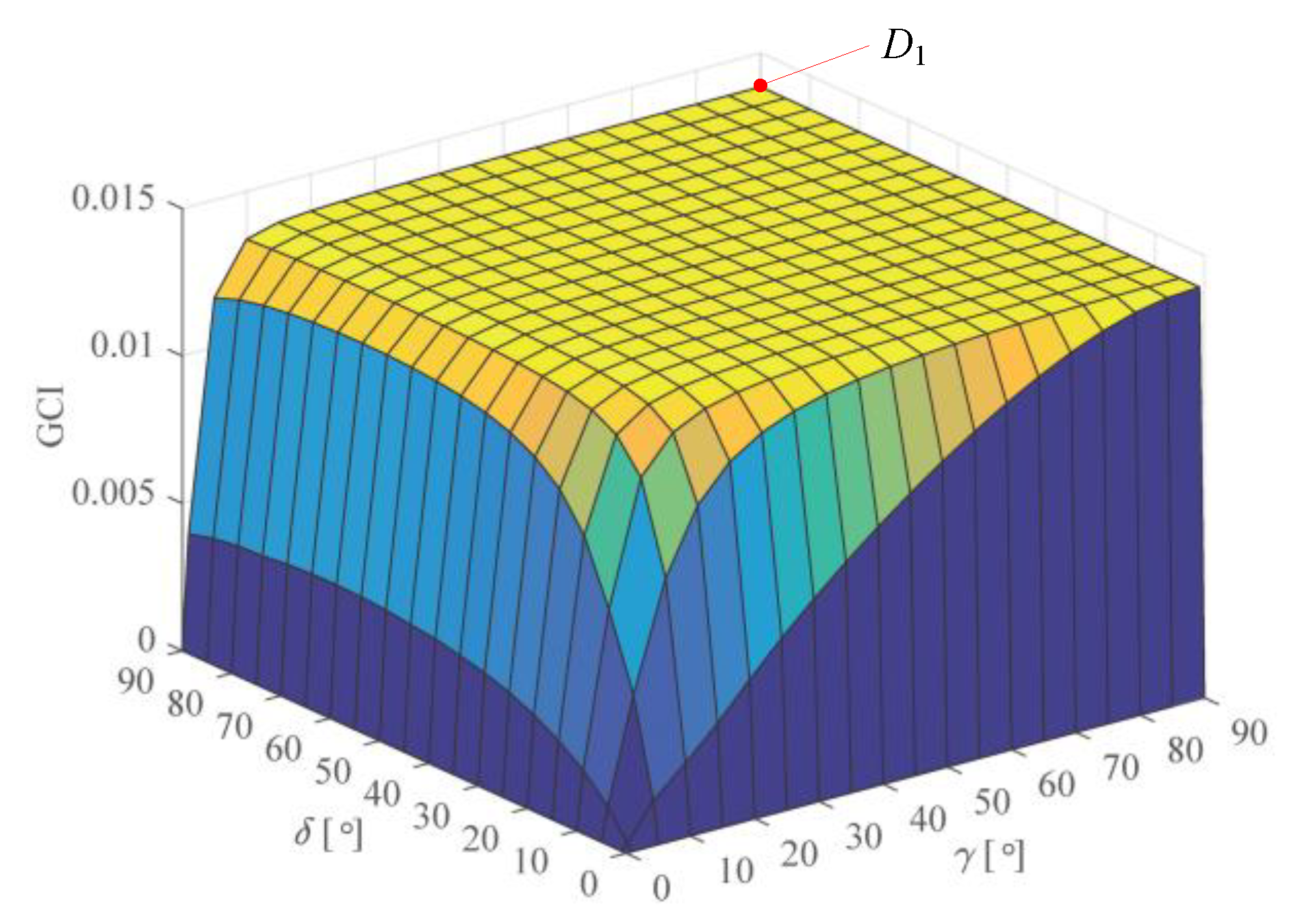
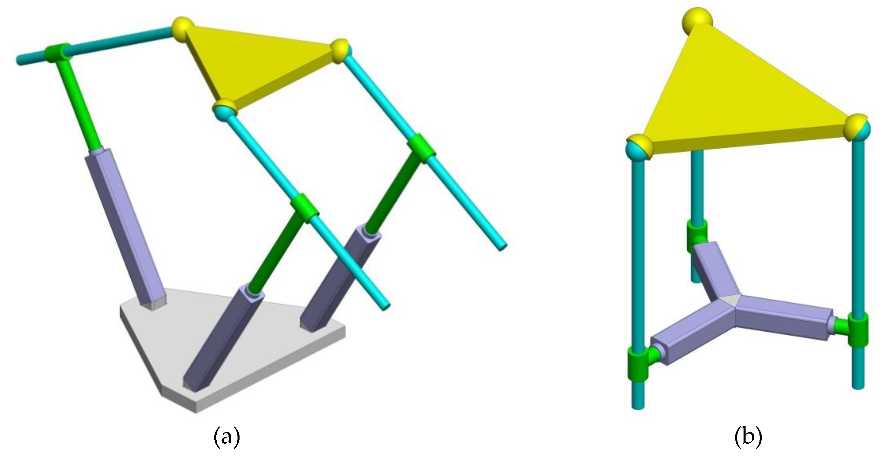
The GCI distribution of the considered 3-PPS PM is depicted in Figure 3. It is found that the dexterity performance of the mechanism is great when 15° ≤ δ ≤ 90° and 15° ≤ γ ≤ 90°. Even the GCI distribution among this zone is nearly the same, there still exists an optimal configuration with the largest GCI = 0.01285 when δ = 90° and γ = 90°, which is presented by point D1 in the plot. The corresponding mechanism is the T-shape 3-PPS PM, as shown in Figure 4. For the T-shape 3-PPS PM, it has a partially decoupled DOF when ψ = 0°, namely, a rotation about the axis of A2A3.

Figure 3.
Global conditioning index (GCI) of the 3-PPS PM.
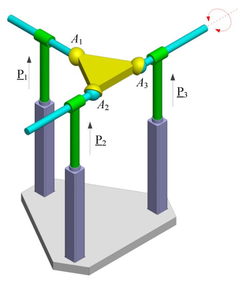
Figure 4.
The T-shape 3-PPS PM.
One can notice that the GCI is equal to 0 when δ = 0° or γ = 0°, two special shapes pertain to this case, as depicted in Figure 5. A zero GCI implies zero LCI in the entire predefined workspace, which means that the mechanism will always be singular. Further analysis of these two shapes will be presented in Section 4.3.
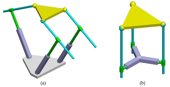
Figure 5.
Two special shapes: (a) δ = 0° and (b) γ = 0°.
4.2. Optimal Design Based on Payload Performance
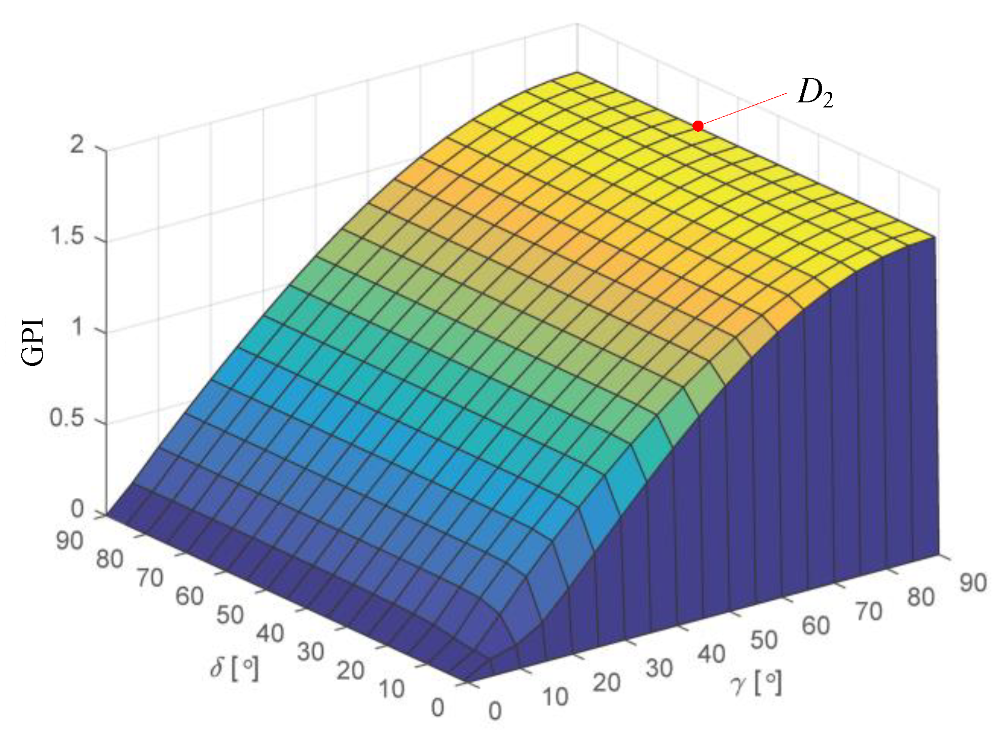
The GPI distribution of the proposed 3-PPS PM is shown in Figure 6. It is seen that the payload performance of the mechanism is great when γ = 90° and 0° < δ ≤ 90°. Moreover, the maximum GPI is equal to 1.7321 at point D2 (δ = 60°, γ = 90°). As shown in Figure 7, the corresponding optimal mechanism is the star-shape 3-PPS PM, whose three PPS limbs are distributed symmetrically, thus the mechanism’s payload capability is improved. Note that the GPI is equal to 0 when δ = 0° or γ = 0°, which means the mechanism can no longer stand external force at these configurations.

Figure 6.
Payload performance of the 3-PPS PM.
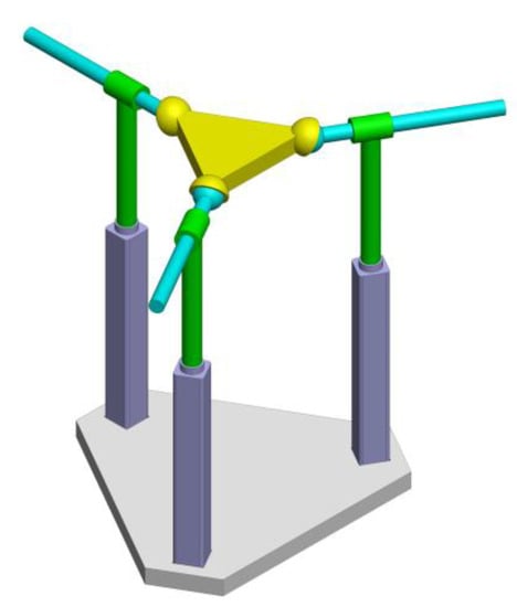
Figure 7.
The star-shaped 3-PPS PM.
4.3. Analysis of Shape Singularity
Shape singularity is a special type of singularity associated with special designs of the base or mobile platforms that lead to a singularity in all configurations, which means it is configuration independent. The platform shape of the PM under shape singularity is called a singular shape. As reported in Reference [18], shape singularity of the planar PM under study is identified by a zero GCI. From the GCI analysis above, the two special shapes (δ = 0°, γ = 0°) are possible singular shapes, due to the fact that the numerical calculation of GCI covers only a predefined workspace, not the entire one.
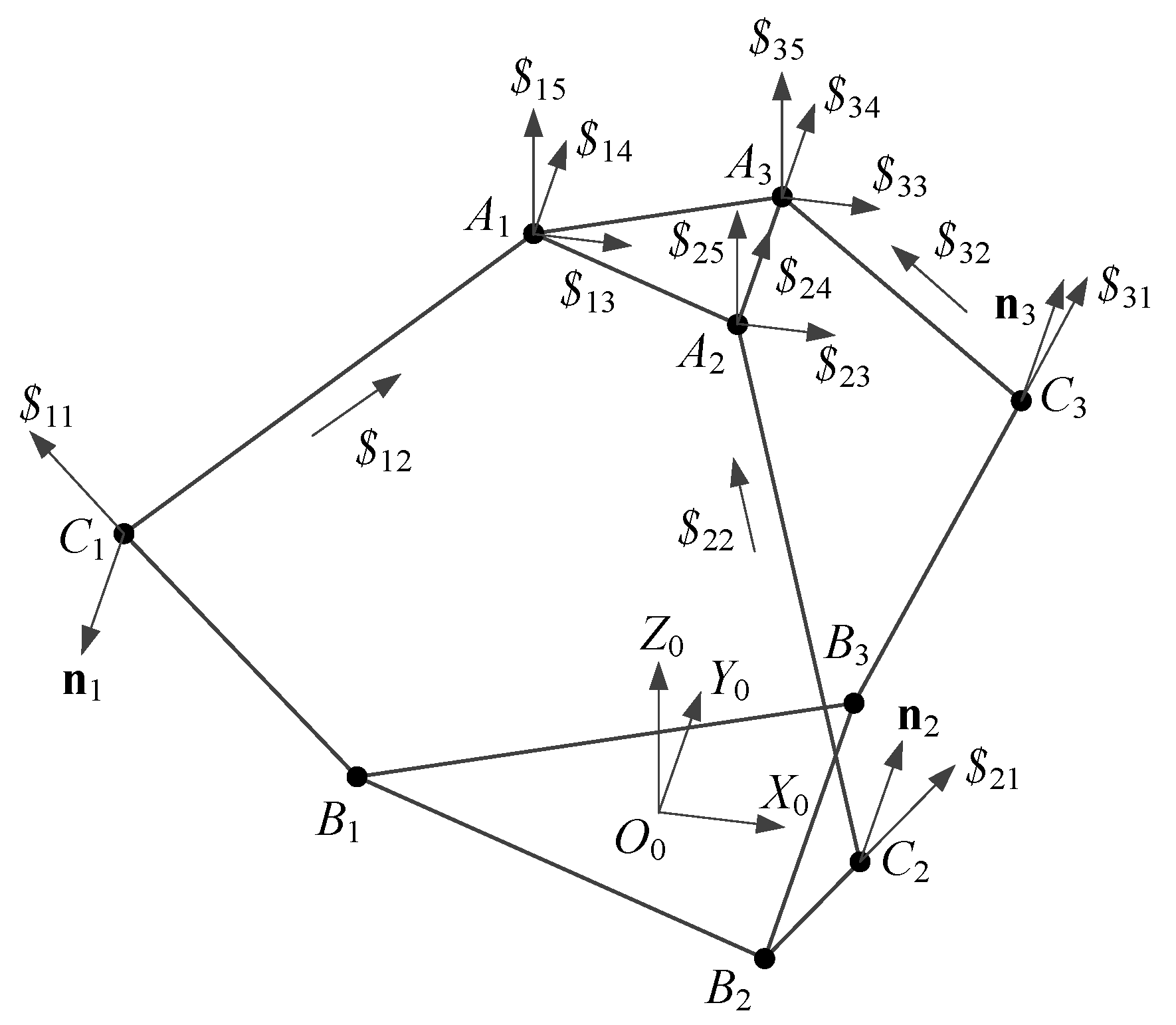
It is well known that screw theory [22] is a useful approach for singularity analysis. In this section, screw theory is applied to shape singularity analysis of the proposed 3-PPS PM. As shown in Figure 8, the considered mechanism is described by screws. Taking the first limb as an example, the twist screws can be written as:
where j and k represent the unit vectors of Y0- and Z0-axis, respectively.
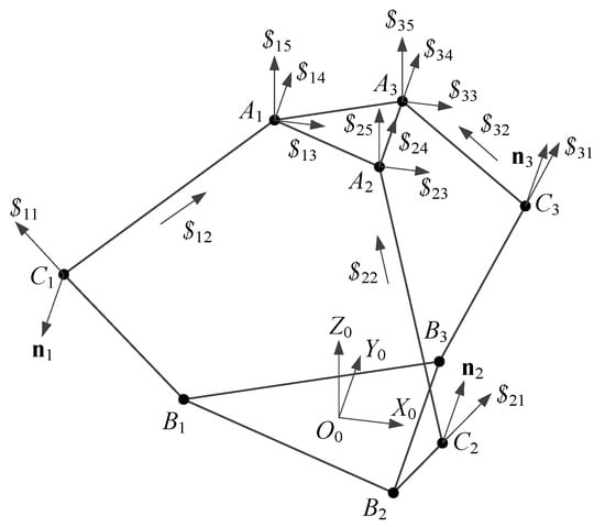
Figure 8.
The general 3-PPS PM described by screws.
When the actuator is locked, the wrench screws of the first limb are:
where ni = gi × fi.
In a similar way, the wrench screws of the other two limbs can be expressed as:
Then the system of wrench screws of the 3-PPS PM can be written as:
which also can be expressed in matrix as:
At ordinary poses, the rank of Q is equal to 6, which means the manipulator is fully constrained and has no singularity. On the other hand, if shape singularity exists, Q is singular.
The two possible singular shapes as discussed in Section 4.1 are considered, and they are described by screws as shown in Figure 9. With regard to δ = 0°, as shown in Figure 9a, the wrench screws can be obtained as:
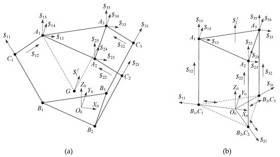
Figure 9.
Two possible singular shapes of the 3-PPS PM: (a) δ = 0° and (b) γ = 0°
The reciprocal screw of the wrench screws is:
which means the MP can rotate about an axis parallel to Y0-axis which passing through point G, even all the actuators are locked. The position vector of point G is:
The reciprocal screw of the wrench screws is:
which means the MP can translate along Z0-axis without actuating all the actuators.
Based on the analysis above, the two considered special shapes are proved to be singular shapes.
4.4. Compliance Performance of Shape Singularity and Its Application
Shape singularity can have some practical implication in PM design. One is the adjustment of robot compliance. Robot compliance is important in automation applications which require a strong interaction between the robot and the environment, while passive and active compliance are two usually used compliance [23]. For passive compliance, it contains an elastic element, e.g., a spring which can store energy. On the other hand, active compliance is based on the control of stiff actuators to mimic the behavior of the spring [24]. It is known that a mechanism will obtain great compliance at the zones near singular configurations. With the shape singularity, it is possible to adjust the PMs’ compliance by means of shape adjustment.
According to Equation (13), the distribution of compliance performance of the proposed 3-PPS PM is obtained and depicted in Figure 10. It is found that the GSI changes significantly for the PM close to shape singularity (δ = 0°, γ = 0°), while the zones near the shape singularity own great compliance. On the other hand, the compliance performances of the zones far away from shape singularity are very poor.
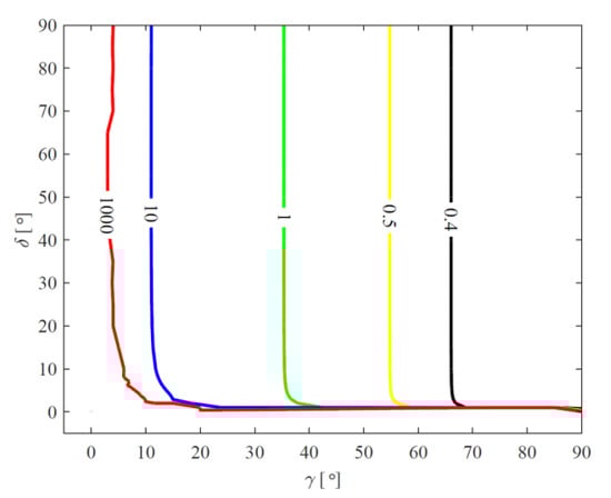
Figure 10.
Compliance performance of the 3-PPS PM.
The inherent great compliance of shape singularity can be applied to mechanism design. Here, adjustable compliance is proposed, to be exact, the compliance is adjusted by changing the shape of the mechanism. As shown in Figure 11, the second and third PPS limbs of the considered PM are attached to the base by revolute joints, and the axis of the rotation is perpendicular to the base. R is the actuator of the shape adjusting mechanism, which is used to change the shape of the base. At the positioning stage, R is locked, namely, the base is fixed with the non-singular shape. The mechanism will possess a good stiffness performance, which makes precision positioning possible. At the stage of interaction with the environment, R will drive the two limbs to the singular shape (δ = 0°), then the mechanism could own a great compliance performance under the singular shape.
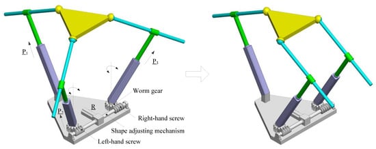
Figure 11.
Compliance adjustment.
5. Discussion and Conclusions
In this work, aimed at optimal design and shape singularity analysis, a parametric kinematic model of the considered spatial 3-PPS PM is established. With this model, the inverse position and Jacobian analyses are carried out. In the optimal design, dexterity and payload performance are considered, from which two optimal configurations are obtained. Performance evaluation shows that the T-shaped one possesses the best dexterity performance, while the star-shaped one exhibits the best payload performance. Moreover, both the dexterity and payload performances of the PM with γ = 90° and 0° < δ ≤ 90° are great. On the basis of dexterity analysis, two possible singular shapes (δ = 0°, γ = 0°) are pointed out. Since screw theory is an effective approach for singularity analysis, it is applied to the identification of the shape singularity, and the result coincides with the performance analysis.
A contribution of this work is the establishment of a parametric model of the 3-PPS PM. By including the shape parameters of the platforms, the model allows us to investigate the influence of the platforms’ shape on the dexterity and payload performances, while shape parameters are rarely considered in other studies [13,14,15,16]. The optimal shape designs in this work show the significance of this model.
Another contribution is the identification and generalization of shape singularity. Here, we provide a method to identify shape singularity. Firstly, possible shape singularity is indicated by dexterity index. Then, screw theory is applied to identify shape singularity. Moreover, shape singularity is generalized from planar PMs to spatial PMs, while it is only reported in planar PMs before in Reference [18].
The last contribution is the application of shape singularity. In related studies, [2,12,22], the singularity is identified with the purpose to eliminate the singularity from workspace of the manipulators. In this work, we find that shape singularity could inspire novel mechanism design. A PM with shape singularity could find potential applications in assembly, as it can provide high compliance due to the presence of the instantaneous center of rotation, thus a remote center of compliance can be formed.
In this work, only two major performance indices are considered for optimal design; other indices should be selected according to the working conditions. On the other hand, the shape singularity of the other PMs should be verified. Needless to say, new compliant PMs with shape singularity and their applications will be topics of future research.
Funding
This work is financially supported by the National Natural Science Foundation of China (U1530138 & No.51605059), the Scientific Research Foundation of Chongqing University of Technology.
Acknowledgments
The author acknowledges Shaoping Bai, Aalborg University, Denmark, for the discussion and comments.
Conflicts of Interest
The authors declare no conflict of interest.
References
- Ebrahimi, S. Dynamic performance evaluation of serial and parallel RPR manipulators with flexible intermediate links. Iran. J. Sci. Technol. Trans. Mech. Eng. 2016, 40, 1–12. [Google Scholar] [CrossRef]
- Wu, X.; Xie, Z. Forward kinematics analysis of a novel 3-DOF parallel manipulator. Sci. Iran. Trans. B Mech. Eng. 2019, 26, 346–357. [Google Scholar] [CrossRef]
- Tsai, L.; Joshi, S. Kinematics and optimization of a spatial 3-UPU parallel manipulator. J. Mech. Des. 2000, 122, 439–446. [Google Scholar] [CrossRef]
- Rezaei, A.; Akbarzadeh, A.; Nia, P.M.; Akbarzadeht, M. Position, Jacobian and workspace analysis of a 3-PSP spatial parallel manipulator. Robot. Comput. Integr. Manufact. 2013, 29, 158–173. [Google Scholar] [CrossRef]
- Zhao, J.S.; Yun, Y.; Wang, L.P.; Wang, J.S.; Dong, J.X. Investigation of the forward kinematics of the Gough-Stewart manipulator with natural coordinates. Int. J. Adv. Manuf. Technol. 2006, 30, 700–716. [Google Scholar] [CrossRef]
- Bai, S.; Caro, S. Design and analysis of a 3-PPR planar robot with U-shape base. In Proceedings of the 2009 International Conference on Advanced Robotics, Munich, Germany, 22–26 June 2009; pp. 1–6. [Google Scholar]
- Wu, G.; Bai, S.; Kepler, J.A.; Caro, S. Error modeling and experimental validation of a planar 3-PPR parallel manipulator with joint clearances. J. Mech. Robot. 2012, 4, 041008. [Google Scholar] [CrossRef]
- Stock, M.; Miller, K. Optimal kinematic design of spatial parallel manipulators: Application to linear Delta robot. J. Mech. Des. 2003, 125, 292–301. [Google Scholar] [CrossRef]
- Xu, Q.; Li, Y. An investigation on mobility and stiffness of a 3-DOF translational parallel manipulator via screw theory. Robot. Comput. Integr. Manuf. 2008, 24, 402–414. [Google Scholar] [CrossRef]
- Liu, X.J.; Wang, J.; Pritschow, G. A new family of spatial 3-DOF fully-parallel manipulators with high rotational capability. Mech. Mach. Theory 2005, 40, 475–494. [Google Scholar] [CrossRef]
- Bonev, I.A. Direct kinematics of zero-torsion parallel mechanisms. In Proceedings of the IEEE International Conference on Robotics and Automation, Pasadena, CA, USA, 19–23 May 2008; pp. 3851–3856. [Google Scholar]
- Briot, S.; Bonev, I.A. Singularity analysis of zero-torsion parallel mechanisms. In Proceedings of the IEEE/RSJ International Conference on Intelligent Robots and Systems, Pasadena, CA, USA, 19–23 May 2008; pp. 1952–1957. [Google Scholar]
- Zhao, J.S.; Chu, F.; Wang, L.P.; Feng, Z.J. Instantaneous mobility and constraint of a 3-PPS parallel mechanism. In Proceedings of the National Conference on Mechanisms and Machine, Durgapur, India, 17–18 December 2008; pp. 221–227. [Google Scholar]
- Ma, K.; Yang, G. Kinematic design of a 3-DOF force-controlled end-effector module. In Proceedings of the 2016 IEEE 11th Conference on Industrial Electronics and Applications (ICIEA), Hefei, China, 5–7 June 2016; pp. 1084–1089. [Google Scholar]
- Yang, G.; Teo, T.J.; Chen, I.M.; Lin, W. Analysis and design of a 3-DOF flexure-based zero-torsion parallel manipulator for nano-alignment applications. In Proceedings of the IEEE International Conference on Robotics and Automation, Shanghai, China, 9–13 May 2011; pp. 2751–2756. [Google Scholar]
- Teo, T.J.; Chen, I.M.; Yang, G. A large deflection and high payload flexure-based parallel manipulator for UV nanoimprint lithography: Part II. Stiffness modeling and performance evaluation. Precis. Eng. 2014, 38, 872–884. [Google Scholar] [CrossRef]
- Ruggiu, M. Position analysis, workspace, and optimization of a 3-PPS spatial manipulator. J. Mech. Des. 2009, 131, 051010. [Google Scholar] [CrossRef]
- Wu, X.; Xie, Z.; Kepler, J.A.; Bai, S. A parametric model of 3-PPR planar parallel manipulators for optimum shape design of platforms. Mech. Mach. Theory 2017, 118, 139–153. [Google Scholar] [CrossRef]
- Gosselin, C.; Angeles, J. A global performance index for the kinematic optimization of robotic manipulators. J. Mech. Des. 1991, 113, 220–226. [Google Scholar] [CrossRef]
- Wu, J.; Wang, J.; Wang, L.; You, Z. Performance comparison of three planar 3-DOF parallel manipulators with 4-RRR, 3-RRR and 2-RRR structures. Mechatronics 2010, 20, 510–517. [Google Scholar] [CrossRef]
- Gosselin, C. Stiffness mapping for parallel manipulators. IEEE Trans. Robot. Autom. 1990, 6, 377–382. [Google Scholar] [CrossRef]
- Bonev, I.A.; Zlatanov, D.; Gosselin, C.M. Singularity analysis of 3-DOF planar parallel mechanisms via screw theory. J. Mech. Des. 2003, 125, 573–581. [Google Scholar] [CrossRef]
- Schutter, J.D.; Brussel, H.V. Compliant Robot Motion: I. A Formalism for Specifying Compliant Motion Tasks; Sage Publications, Inc.: Thousand Oaks, CA, USA, 1988. [Google Scholar]
- Albu-Schäffer, A.; Eiberger, O.; Grebenstein, M.; Haddadin, S.; Ott, C.; Wimböck, T.; Wolf, S.; Hirzinger, G. Soft robotics: From torque feedback controlled lightweight robots to intrinsically compliant systems. IEEE Robot. Automat. Mag. 2008, 15, 20–30. [Google Scholar] [CrossRef]


© 2019 by the author. Licensee MDPI, Basel, Switzerland. This article is an open access article distributed under the terms and conditions of the Creative Commons Attribution (CC BY) license (http://creativecommons.org/licenses/by/4.0/).