Article

Automatic Registration of Multi-Projector Based on Coded Structured Light

The State Key Laboratory of VR Technology & Systems, Beihang University, Beijing 100191, China
*
Author to whom correspondence should be addressed.
Symmetry 2019, 11(11), 1397; https://doi.org/10.3390/sym11111397
Submission received: 19 October 2019 / Revised: 4 November 2019 / Accepted: 8 November 2019 / Published: 12 November 2019

Abstract

:
Multi-projector display systems are widely used in virtual reality, flight simulators, and other entertainment systems. Geometric distortion and color inconsistency are two key problems to be solved. In this paper a geometric correction principle is theoretically demonstrated and a consistency principle of geometric correction is first proposed. A new method of automatic registration of a multi-projector on a curved screen is put forward. Two pairs of binocular-cameras are used to reconstruct the curved screen. To capture feature points of the curved screen precisely, a group of red-blue coded structured light images is designed to be projected onto the screen. Geometric homography between each projector and the curved screen is calculated to gain a pre-warp template. Work which can gain a seamless display is illustrated by a six-projector system on the curved screen.

1. Introduction

Tiling multiple projectors on curved displays is a common way to build high resolution, large-scale, and seamless vision systems in virtual reality. In this vision system, viewers can receive an immersive visual experience. Multi-projector systems form a seamless rendering view by overlapping projections onto each other. The challenges are to calibrate the geometric distortions due to projections onto the curved surface and to align and blend the overlapped parts of the projections both in geometry and color.
In the study of the geometric correction of multi-projector systems, the content of research has developed from multi-projector geometric correction on plane screens [1,2] to multi-projector geometric correction on curved screens [3,4], and the method of geometric correction has also developed from mechanical structure correction [5,6] to camera-based geometric correction [7,8]. However, the researchers mainly focus on the method of geometric correction, and there is a lack of theoretical research on the principle of off-line geometric correction. In this paper, the geometric correction of a multi-projector system is analyzed theoretically and the theoretical basis of off-line geometric correction (the consistency of geometric correction) is demonstrated for the first time.
Camera-based geometric correction is a kind of method with high accuracy. In this method the camera is used to capture the feature image of the system to get the geometric description of the screen. There are many different feature images which have developed from the physical mark on the screen [9,10] to the projection mark on the screen [11,12]. Among these, structured light image is a focus of research. Researchers use a variety of structured light methods to calibrate the features of the projector system [13,14]. These works, however, which involve projection on a curved surface, tackle the problem in a one-dimensional fashion, using multiple projections horizontally on the curved screen [15]. This paper presents a geometric correction method based on red-blue structured light in a two-dimensional (horizontal and vertical) manner.
In this paper, the geometric correction principle of a multi-projection system is theoretically demonstrated and the consistency principle of geometric correction is proposed. The work adopts binocular vision to achieve the registration of a multi-projector on a parameterized surface in a two-dimensional (horizontal and vertical) manner. It proposes a novel geometric calibration approach based on red-blue gray code structured light. Section 2 analyzes the principle of geometric registration and proposes the consistency principle of geometric correction. In Section 3, the method of geometric registration is presented. Section 4 gives results and performance and Section 5 provides our conclusion.

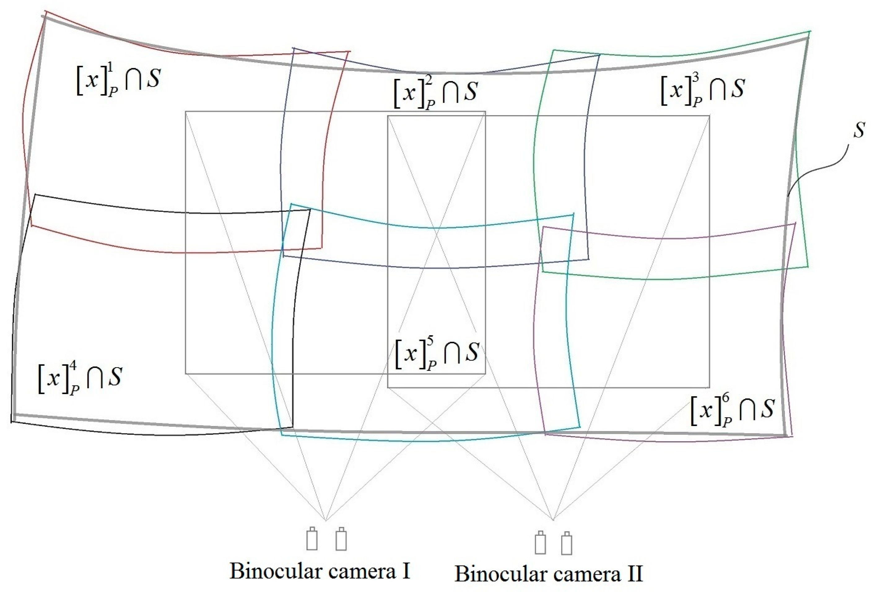
2. Geometric Registration Principle

Multi-projector systems are an effective way to achieve a large-scale display with sufficient resolution. The pictures S i , j projected by several projectors P i , j ( i = 1 , 2 , , n ,   j = 1 , 2 , , m ) on the display surface (screen) S are connected with each other to form a unified large-scale picture. This large-scale picture realizes a wide field of view. Each picture projected on the curved screen is warped and the overlapping part of the projections is diverged. The issue is how to generate images projected on a curved screen that appear correctly to the viewer.

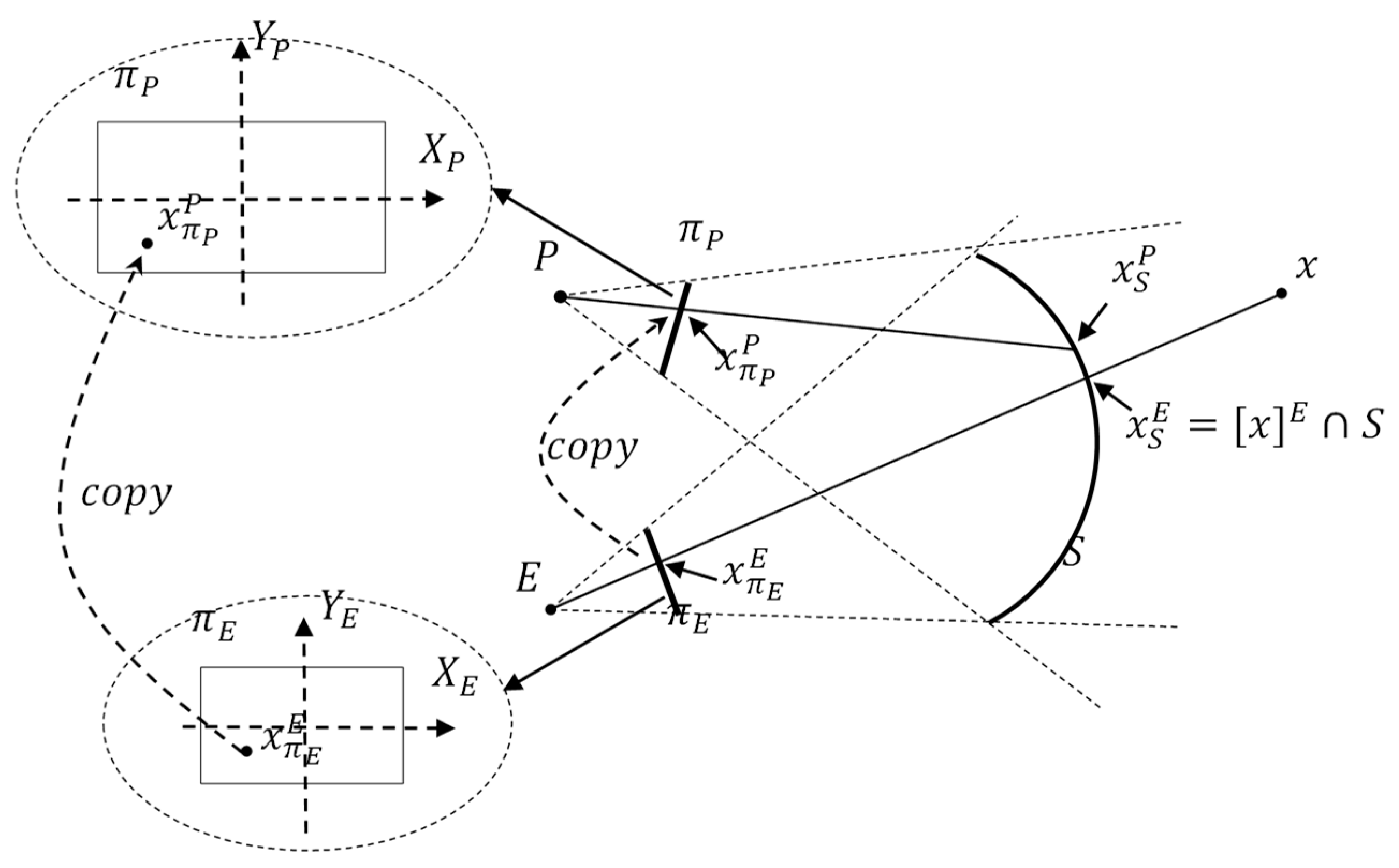
2.1. Coordinate System

In order to describe the geometric distortion and correction, the following definitions of the relevant coordinate system are given.
1.  Virtual world coordinate system C W
Depending on C W , the location of the model in a three-dimensional scene is represented.
2.  Eye point coordinate system C E
C E describes the spatial position of the monocular observation point. For discussion convenience, we hold that the Z axis of C E is orthogonal to the image plane π E and passes through the geometric center of π E .
3.  Camera coordinate system C C
C C describes the spatial position of the cameras used in automatic correction.
4.  Projector coordinate system C P
C P describes the spatial position of the projector. For discussion convenience, we hold that the Z axis of C P is orthogonal to the image plane π P and passes through the geometric center of π P .
The affine transformation A ( R _ i j , t _ i j ) is used between any two coordinate systems C i , C j ( i , j { E , P , C , W } ) , and ( R _ i j ^ ( 3 × 3 ) , t _ i j ^ 3 ) .

2.2. Consistency of Geometric Correction

In a multi-projector system, the basic calculation and display process is divided into two steps. Firstly, through perspective projection centered on an eye point E , a two-dimensional projection picture I of a three-dimensional space scene is generated on image plane π E . Secondly, picture I is projected through projection plane π P onto the display surface by the projector, as shown in Figure 1.
The perspective projection centered on eye point E represents the viewer’s perspective with orientation on the curved screen. The perspective projection centered on projection point P represents the projectors’ perspective. Geometric distortion of the multi-projector system is caused by the inconsistency of the projectors’ perspective and the viewer’s perspective. If the system has the same projectors’ perspective and viewer’s perspective, the correct image can be seen at the eye point, regardless of the screen shape. The process of geometric distortion correcting is defined as geometric registration.
Any point x 3 in the frustum can be expressed as x E = ( x E , y E , z E ) T in C E . Define equivalent classes [ x ] E in projection space P ( C E ) based on C E as
[ x ] E = ( x E / ω y E / ω z E / ω ) ,   ω
where z E / ω = d E . The corresponding point of x on the image plane π E is
x π E E = π E [ x ] E = d E ( x E / z E y E / z E 1 ) = d E μ E ( x )
Then, the corresponding point of x on the screen S in C E is
x S E = [ x ] E S = d S E μ E ( x )
The process of transferring an image from image plane π E to projection plane π P is defined as π E c o p y π P , and we define the transformation
S P = [ S x 0 0 0 S y 0 0 0 d P / d E ]
where S x = u n i t l e n g t h o f X P u n i t l e n g t h o f X E , S y = u n i t l e n g t h o f Y P u n i t l e n g t h o f Y E , and the corresponding point x on the projection plane π P can be expressed as x π P P = S P x π E E = d P μ P ( x ) . Though the projector, the point on the screen S in C P is x S P = d S P μ P ( x ) , where μ P ( x ) = ( d E d P x E z E , d E d P y E z E , 1 ) T .
Geometric distortion on screen S can be quantified by geometric error δ S e ( x ) :
δ S e ( x ) = x S E ( R E P x S P + p E P )
δ S e ( x ) is the error observed on screen S in the eye point coordinate system C E . Geometric correction of this error requires the processing of geometric error on image plane π E .
Point [ x ] E S in C P is expressed as
( [ x ] E S ) P = R P E x S E + p P E
and its projective point on projection plane π P is
[ ( [ x ] E S ) P ] π P = d P d S P ( R P E x S E + p P E )
Then, through the process π P c o p y π E , the position of this point on image plane π E is
x ˜ π E E = S P 1 ( d P d S P ( R P E x S E + p P E ) )
We can gain the geometric error δ π E e ( x ) on image plane π E
δ π E e ( x ) = x π E E x ˜ π E E
where
x ˜ π E E = S P 1 ( d S E ε 3 T ( d S E R P E μ E ( x ) + p P E ) d P ( R P E x S E + 1 d S E p P E ) ) = φ ( d S E , μ E ( x ) )
and e 3 T = ( 0 , 0 , 1 ) .
When the ray direction μ E ( x ) is determined, the geometric error δ π E e ( x ) is only related to d S E , which is the coordinate in the Z axis of the intersection of the ray and the screen S in C E .
From the above formula, the following conclusion can be drawn.
  • When μ E ( x ) remains unchanged, for each point on the screen S and on the image plane π E , the geometric error is determined and only related to the structural parameters of the multi-projector system, not to the virtual scene (consistency of geometric correction).
The consistency principle of geometric correction ensures that geometric correction can be carried out by determining the structural parameters of the multi-projector system and that the process can be done offline.

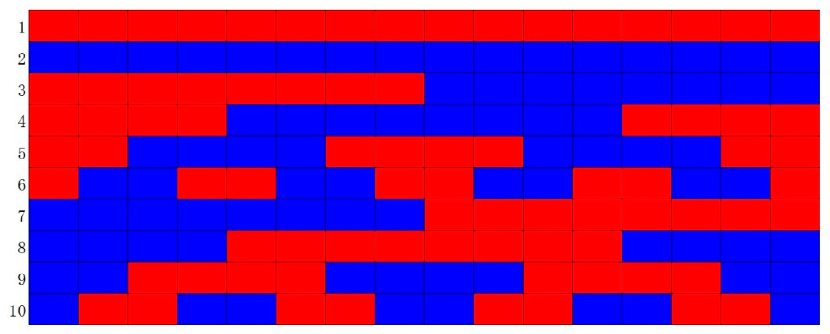
3. Geometric Correction

One of the most important tasks in determining structural parameters is to determine the geometric description of the screen S in the eye point coordinate system C E . We use binocular cameras to calculate the geometric description of screen S . Figure 2 shows that the binocular cameras capture the projections on the curved screen.

3.1. Geometric Distortion Correction

To correct geometric distortion, three components should be known: (a) equivalent classes [ x ] E , which express the viewer’s perspective with orientation on the curved screen, and can be calculated by the geometric dimensions of the system; (b) the geometric description of screen S , which can be obtained by three-dimensional reconstruction of feature points; and (c) equivalent classes [ x ] P i which express the projectors’ perspective. The mosaic method for a seamless multi-projector system with these three components in two-dimensionality is given as follows:
Firstly, render a 3D mesh S of the curved screen using the viewer’s perspective specified.
Secondly, for each projector P j , map the correspondences’ portion of the 3D mesh to the projection plane π P j by the transformation H P j 1 , after which the pre-warp template x T in 2D is obtained.
Thirdly, through projecting the pre-warp template x T on the screen, a geometric seamless image can be seen at the location of the viewer.
Note that these calculations are registered to a common coordinate frame.

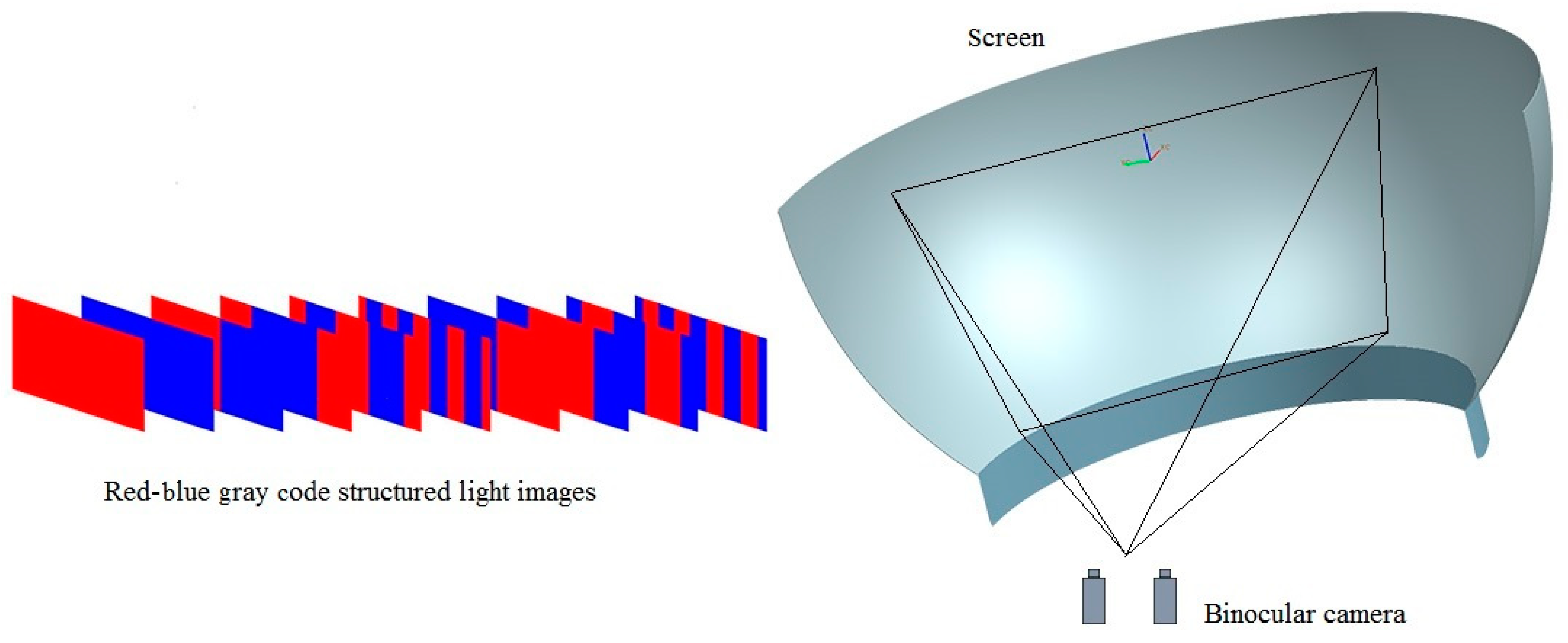
3.2. Geometric Description of Screen

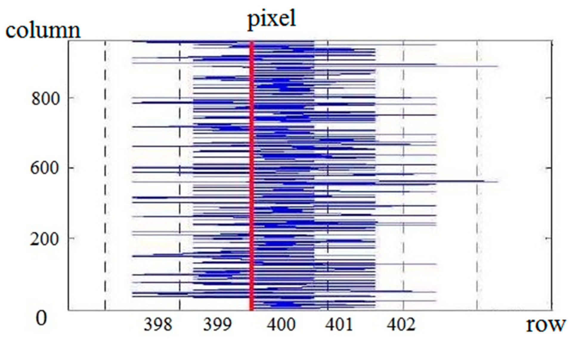
3.2.1. Feature Points

With a multi-projector system, in the case of two-dimensionality projection, it is hard to capture and reconstruct the feature points, since there are overlapping parts of adjacent projections distributing in the vertical and horizontal directions.
To keep the curved screen clean without physical markers, we employ the red-blue gray code (RBGC) structured light images as the feature images. The gray code for decimal 0 rolls over to decimal 15 with only one switch change, so the coding has excellent anti-interference performance. The designed sequence of 4 bits RBGC is shown in Figure 3, in which the red and blue grids represent 0 and 1, respectively, in RBGC, and the number expresses the sequence of this structured light image.
The RBGC images projected to the curved screen are the feature images to be captured by the calibrated cameras. The RBGC images decode to the gray grading images, for which the number of the gray grades is 2 R , where R is the bit of the gray code. The gray value of the nth gray grade is n 2 8 R , and if the value is decoded as G , n can be obtained as [16], i.e.,
n = G 2 8 R ( n { 0 , 1 , 2 , , 2 R 1 } )
The frame buffer coordinate of the nth gray grade’s edge which neighbors the lower gray grade is
b l = n 2 R , 0 b l < 1
Substituting Equation (11) into Equation (12), the value of b l can be determined as
b l = G / 256
The decoded RBGC data is gained.
When projecting the structured light images to the screen in horizontal and vertical orientations, respectively, for each projector, the intersections of horizontal and vertical stripes are the feature points. An edge detection method for RBGC is introduced in the next section.

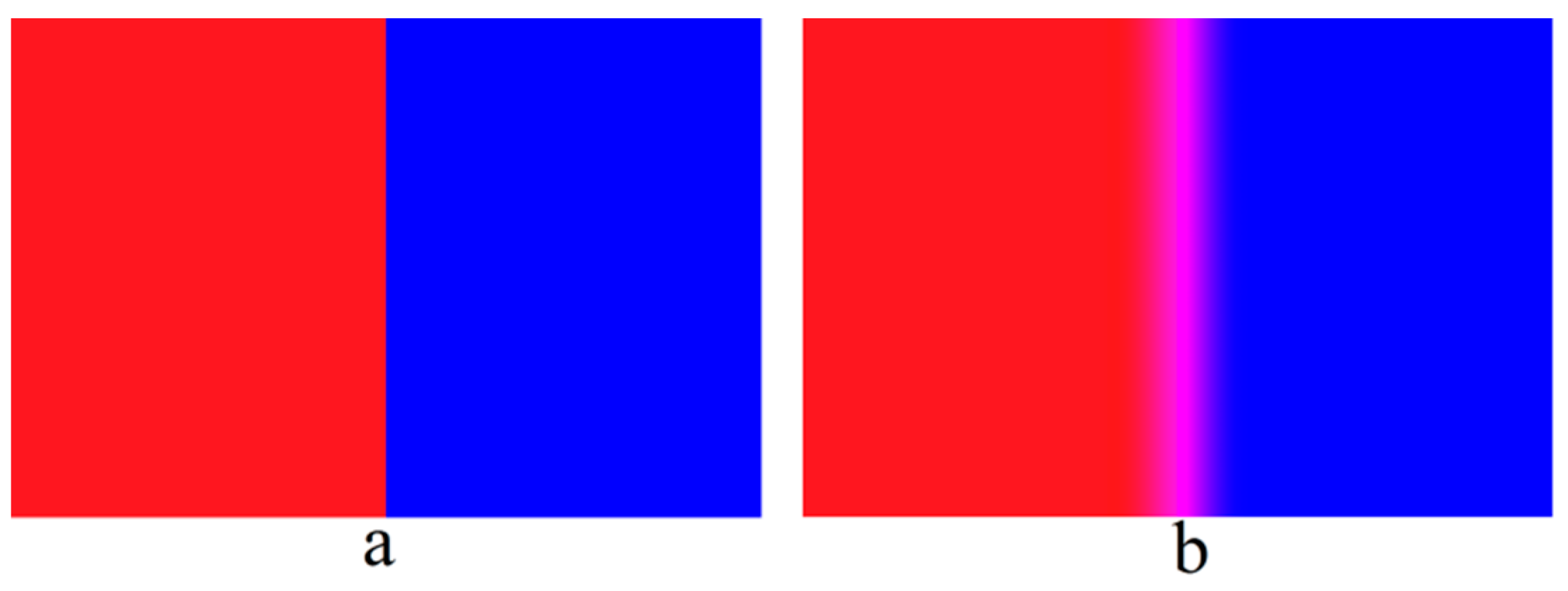
3.2.2. Edge Detection for RBGC

As the RBGC images are projected on the screen, deformation of the red-blue stripes appears. There are two reasons for which the accuracy of deformation capturing is affected: one is that the curved screen causes dislocation of the projected pixels on the red-blue edge and the other is that the camera pixels capturing the red-blue edge are dislocated and blurred. In order to improve the accuracy of edge detection, we design here an edge detection method for RBGC.
A red-blue stripe simulation pattern is constructed and the red-blue edge of the image is processed by divergence as shown in Figure 4. The divergence edge is established as
{ R ( x 0 / 2 + i , y ) = R 0 cos ( i π / 2 n ) B ( x 0 / 2 i , y ) = B 0 cos ( i π / 2 n ) ( i [ 0 , n ] )
where R 0 and B 0 are the initial value of the red and blue components, respectively, n = m ( 1 + sin y ) , and m is the initial value of the scattered amplitude of the pixels.
To detect the edge of the red-blue stripe accurately, the red and blue components of the image are obtained by hierarchical processing. In order to reduce noise interference, the red component and the blue component are filtered separately by Gauss filtering to gain images G R and G B . Then, scanning the image point by point, when the red component of the pixel is larger than the blue component G R > G B , the pixel is recorded as R = 1 . At the time G R < G B , the pixel is recorded as R = 0 , and the binary image of the red component is obtained. In the same row, the value of two adjacent pixels whose value has a step is kept and the value of the other adjacent pixels without a step is made to be 0.
Figure 5 shows the partial pixel step change in binary image. The edge of the red and blue stripe image should be at 400 column pixels. According to the data, the maximum error of the edge pixels is 3 pixels, the average error is 0.69 pixels, and the variance is 2.9396 × 10 6 .
After obtaining the discrete pixels, the continuous edge is obtained by curve fitting. The least squares method is used to fit the edge curve of the red-blue stripe.
The RBGC images are projected to screen S , respectively, in horizontal and vertical orientation for each projector, and the edge intersections of horizontal and vertical stripes are the feature points s l i p j . The coordinate of s l i p j in the frame buffer can be expressed by b l and b p as s l i p j b , and the coordinate of s l i p j in the camera can be expressed as s l i p j c . By decoding the gray code, the corresponding relationship between s l i p j b and s l i p j c of the same point can be obtained, and the points on the frame buffer and those captured by the camera can be accurately matched.

3.2.3. Three-Dimensional Reconstruction

In order to obtain a geometric description of screen S , the space coordinates of the feature points are obtained by three-dimensional reconstruction. Expressing an opaque quadric surface in 3D by two arbitrary cameras needs a quadric transfer function ψ . The quadric transfer can be computed from nine or more correspondences.
A space point X which can be expressed as a 4 × 1 vector lies on a quadric surface Q which can be expressed as a symmetric 4 × 4 matrix, whereupon X T Q X = 0 can be gained. The transfer function between the corresponding pixels x in one camera and x in the other camera can be related by
x B x ( q T x ± ( q T x ) 2 x T Q 33 x ) e
There are 21 unknowns in this equation: the quadric Q = [ Q 33 q ; q T 1 ] , a 3 × 3 homography matrix B , and the epipole in homogeneous coordinates, e . These 21 unknowns can be computed by the given pixel correspondences ( x , x ) . The epipole is the image of the center of projection of the first camera in the second camera. Part of this ambiguity is removed by defining
A = B e q T E = q q T Q 33
and the transfer is gained which is [7]
x = A x ± e x T E x
Here, x T E x = 0 defines the outline conic of the quadric in the first camera and A is the homography via the polar plane between the binocular cameras. Note that this equation contains (apart from the overall scale) only one ambiguous degree of freedom resulting from the relative scaling of E and e . This can be removed by introducing an additional normalization constraint such as E ( 3 , 3 ) = 1 . Furthermore, the sign in front of the square root is fixed within an outline conic in the image. As the internal parameters of the binocular cameras are known, a triangulation of corresponding pixels in binocular cameras can be used to compute parameters of quadric transfer { A , E , e } . This involves estimating the quadric Q directly from point correspondences.

3.3. Geometric Description of Projector

In this multi-projector system each projector has its own matrix H P j which reflects the transformation between reconstruction point X i in space and correspondence points x i on the projection plane π P j (equivalent classes [ x ] P j ) as
x i = H p j X i
According to projection geometry, for the projector P j , a transformation consisting of a rotation R P j , a translation T P j and a projection matrix K P j can be obtained by QR decomposition of matrix H P j
H p j = K p j [ R p j | T p j ]
The projection matrix H P j is an upper triangular matrix and the rotation matrix R P j is an orthogonal matrix.

4. Results

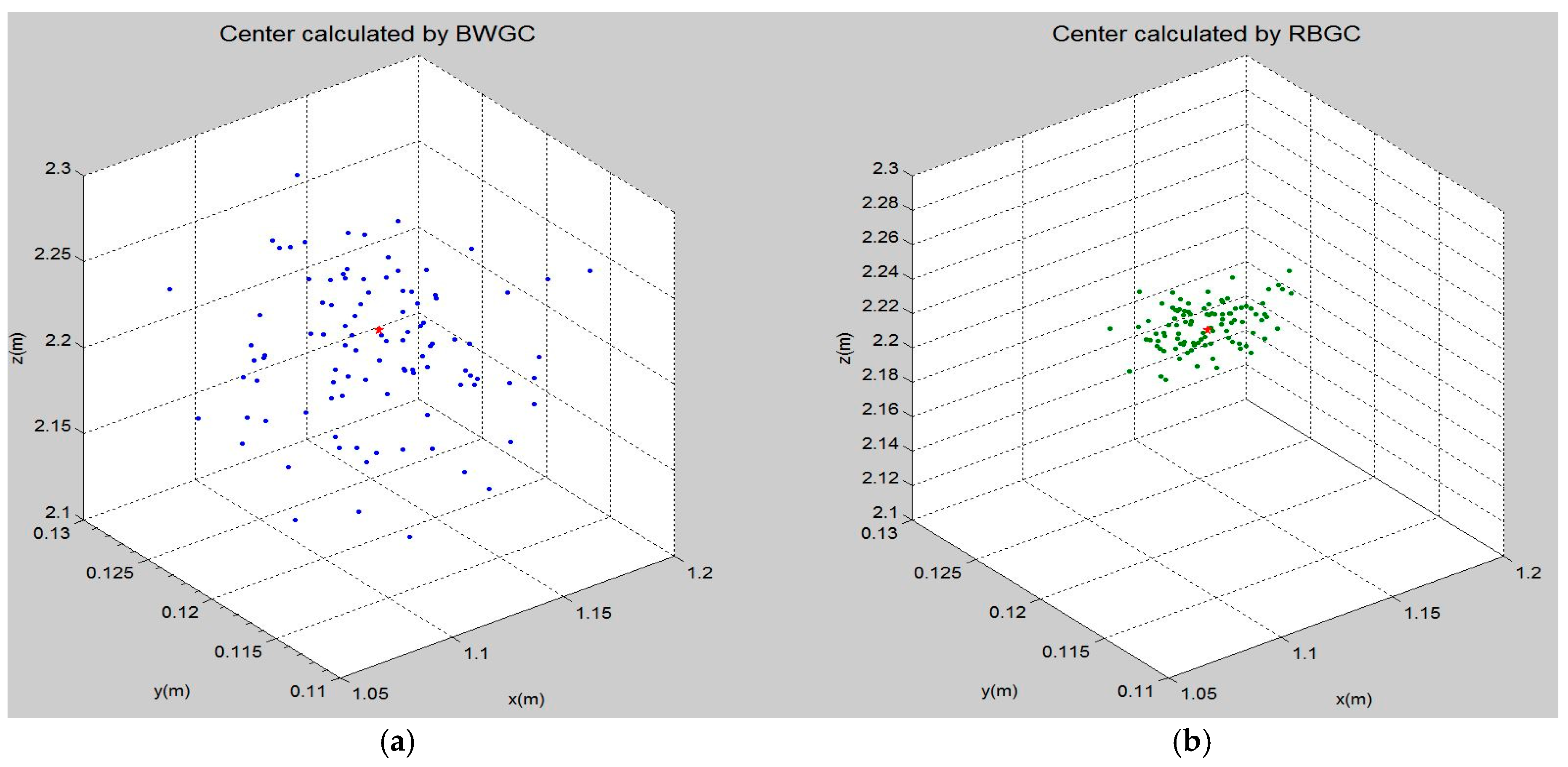
4.1. Feature Points Identification Result

An RBGC structured light image used as a feature is one of the focuses of this paper. In the geometric correction of a multi-projector system, structured light images have been encoded by black-white gray code (BWGC) [17]. When using the camera to capture the feature image, the experimental environment cannot achieve the ideal conditions without ambient light which affects the accuracy of capturing. BWGC structured light is sensitive to the influence of ambient light, so RBGC structured light images are utilized in this paper to reduce the interference of ambient light and to improve the accuracy of capturing.
In the experiment, RBGC structured light and BWGC structured light were respectively projected onto the same screen and the same binocular cameras were used in the same position to capture the feature images. Because the ambient light was different at different times, two kinds of structured light images were captured 100 times at random times. Figure 6 is a schematic diagram of this process, in which a group of vertical RBGC structured light images are shown which are projected onto a curved screen to be captured by binocular cameras.
After reconstructing the feature points of the screen, the parameters of the screen can be fitted. The coordinate of the spherical center of the screen which has its own physical location and measurement location is selected as the evaluation criterion to compare the method based on RBGC with the method based on BWGC, with the experimental results is shown in Figure 7.
In Figure 7, the red pentagon is the center of the sphere in physics and the unit of measurement of the coordinate is the meter. The blue marks in Figure 7a are the center of the sphere calculated using BWGC structured light as the feature image and the green marks in Figure 7b are the center of the sphere calculated using RBGC structured light as the feature image.
From this figure we can ascertain that the green marks are closer to the red pentagon. This means that the results calculated by RBGC structured light are closer to the physical coordinates of the spherical center. In order to measure the results more clearly, the distance between the measured spherical center and the physical spherical center is calculated. The normal probability plot diagram shown in Figure 8 was drawn for the distance obtained from RBGC and the distance obtained from BWGC. The abscissa in the figure is the distance between the measurement center and the physical center. It can be seen from Figure 8a that the results of the calculation of the BWGC structured light are mostly distributed in ( 0 0.01 ) . From Figure 8b we can see that the results of the calculation of the RBGC structured light are mostly distributed in ( 0 0.005 ) . It can be judged that the calculation accuracy of the RBGC is higher.

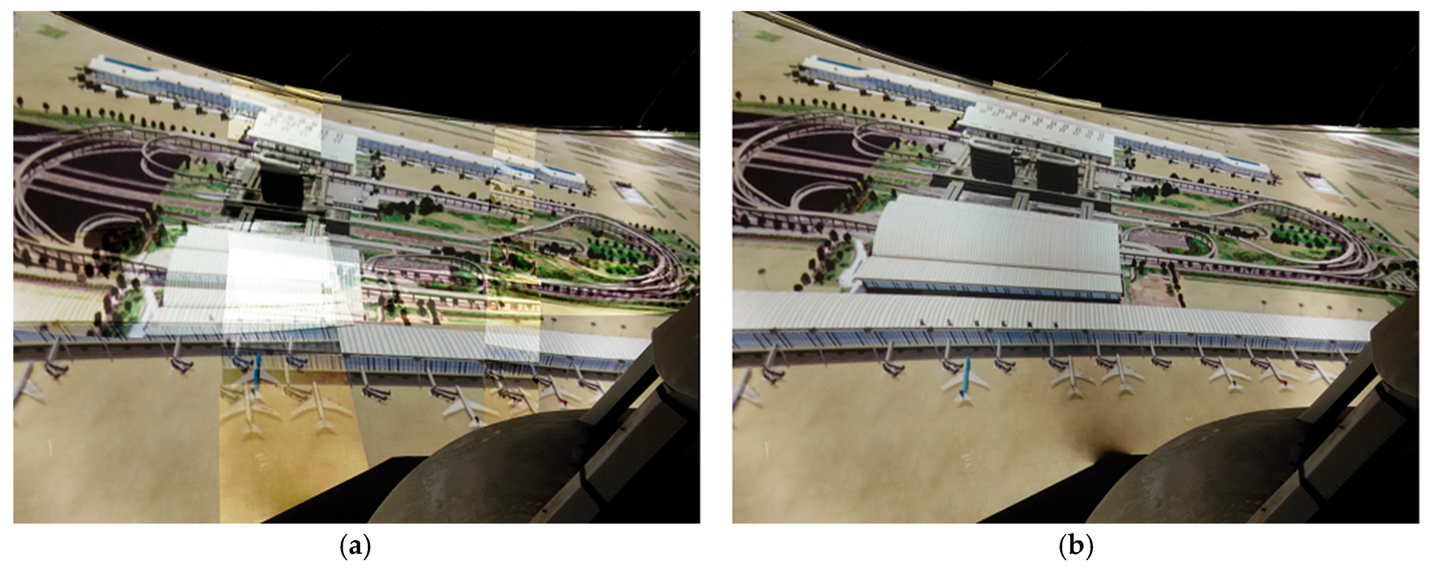
4.2. Geometric Registration Result

A six-channel multi-projector system was used to verify the algorithm. On a 1 / 4 spherical screen with a radius of 3 m, 3 × 2 projectors were used to project the picture on a sphere, as shown in Figure 9a. Each projection image has geometric distortion and the overlapped parts of the images cannot be aligned. The method in this paper is used to register the geometry of the multi-projector system, and a seamless picture is obtained, as shown in Figure 9b.

5. Discussion

Through theoretical analysis of the geometric correction of a multi-projector system, the following conclusion is obtained: geometric error is determined and only related to the structural parameters of the multi-projector system, not to the virtual scene. To gain geometric registration, determining structural parameters is an important task. Red-blue gray code structured light images were used to calculate the geometric description of screen S by binocular cameras. The geometric correction method and results are given in this paper. It is proven that this method is effective and can obtain a seamless, large-scale picture.

Author Contributions

Conceptualization, S.Z. and S.D.; methodology, S.Z. and S.D.; software, S.Z.; validation, S.Z., M.Z., and S.D.; formal analysis, S.Z.; investigation, M.Z.; resources, S.Z.; data curation, S.Z.; writing-original draft preparation, S.Z.; writing-review and editing, M.Z.; visualization, S.Z.; supervision, S.D.; project administration, S.D.; funding acquisition, S.D.

Funding

This research was funded by the National Key Research and Development Plan of China, grant number 2018AAA0102902.

Conflicts of Interest

The authors declare no conflict of interest.

References

  1. Allard, J.; Gouranton, V.; Lecointre, L.; Limet, S.; Melin, E.; Raffin, B.; Robert, S. FlowVR: A Middleware for Large Scale Virtual Reality Applications; Springer: Berlin, Germany, 2003; Volume 12, pp. 497–505. [Google Scholar]
  2. Raffin, B.; Soares, L. PC clusters for virtual reality. In Proceedings of the IEEE Virtual Reality Conference, Alexandria, VA, USA, 25–29 March 2006. [Google Scholar]
  3. Mine, M.R.; Rose, D.; Yang, B.; van Baar, J.; Grundhofer, A. Projection-based augmented reality in Disney theme parks. Computer 2012, 45, 32–40. [Google Scholar] [CrossRef]
  4. Sun, W.; Sobel, I.; Culbertson, B.; Gelb, D.; Robinson, I. Calibrating multi-projector cylindrically curved displays for “wallpaper” projection. In Proceedings of the PROCAMS 2008, Marina del Rey, CA, USA, 10 August 2008. [Google Scholar]
  5. Allen, W.; Ulichney, R. Doubling the addressed resolution of projection displays. SID Symp. Dig. Tech. Papers 2005, 36, 1514–1517. [Google Scholar] [CrossRef]
  6. Damera, V.N.; Chang, N.L. Realizing super-resolution with superimposed projection. In Proceedings of the IEEE Conference on Computer Vision and Pattern Recognition, Minneapolis, MN, USA, 17–22 June 2007; pp. 1–8. [Google Scholar]
  7. Raskar, R.; Van, B.J.; Beardsley, P.; Willwacher, T.; Rao, S.; Forlines, C. iLamps: Geometrically aware and self-configuring projectors. In Proceedings of the ACM Transactions on Graphics, San Diego, CA, USA, 27–31 July 2003; pp. 809–819. [Google Scholar]
  8. Park, J.; Lee, B.U. Defocus and geometric distortion correction for projected images on a curved surface. Appl. Opt. 2016, 55, 896. [Google Scholar] [CrossRef] [PubMed]
  9. Yang, R.; Gotz, D.; Hensley, J.; Towles, H. Pixel Flex: A reconfigurable multi-projector display system. Visualization 2001. In Proceedings of the IEEE Computer Society, San Diego, CA, USA, 8–12 January 2001; pp. 167–554. [Google Scholar]
  10. Raij, A.; Gill, G.; Majumder, A.; Towles, H.; Fuchs, H. A comprehensive, automatic, casually-aligned multi-projector display. In Proceedings of the IEEE International Workshop on Projector-Camera Systems, Nice, France, 13–16 October 2003; pp. 203–211. [Google Scholar]
  11. Raij, A.; Pollefeys, M. Auto-calibration of multi-projector display walls. In Proceedings of the International Conference on Pattern Recognition, Cambridge, UK, 23–26 August 2004; pp. 14–17. [Google Scholar]
  12. Brown, M.; Majumder, A.; Yang, R. Camera-based calibration techniques for seamless multi-projector displays. IEEE Trans. Vis. Comput. Graph. 2005, 11, 193–206. [Google Scholar] [CrossRef] [PubMed]
  13. Chufan, J.; Beatrice, L.; Song, Z. Three-dimensional shape measurement using a structured light system with dual projectors. Appl. Opt. 2018, 57, 3983. [Google Scholar]
  14. Hongyu, W.; Chengdong, W.; Tong, J.; Xiaosheng, Y. Projector calibration algorithm in omnidirectional structured light. In Proceedings of the LIDAR Imaging Detection and Target Recognition, Changchun, China, 23–25 July 2017; p. 11. [Google Scholar]
  15. Xiao, C.; Yang, H.; Su, X. Image alignment algorithm for multi-projector display system based on structured light. J. Southwest Jiaotong Univ. 2012, 10, 790–796. [Google Scholar]
  16. Robert, W.D. The gray code. J. Univers. Comput. Sci. 2007, 13, 1573–1597. [Google Scholar]
  17. Yi, S. Auto-Calibrated Multi-Projector Tiled Display System. Ph.D. Thesis, Beihang University, Beijing, China, December 2012. [Google Scholar]
Figure 1. Geometric distortion and registration sketch map.
Symmetry 11 01397 g001
Figure 2. The schematic of binocular camera capturing.
Symmetry 11 01397 g002
Figure 3. Red-blue gray code (RBGC) image.
Symmetry 11 01397 g003
Figure 4. Red-blue stripe pattern. (a) Ideal red-blue edge; (b) divergence edge.
Symmetry 11 01397 g004
Figure 5. Statistic image of partial pixel step change in binary image.
Symmetry 11 01397 g005
Figure 6. Schematic diagram of capturing vertical RBGC structured light images.
Symmetry 11 01397 g006
Figure 7. The center location of the sphere. (a) Center calculated by black-white gray code (BWGC); (b) center calculated by RBGC.
Symmetry 11 01397 g007
Figure 8. Normal probability plot diagram for the distance between the measured spherical center and the physical spherical center. (a) Distance obtained from BWGC; (b) distance obtained from RBGC.
Symmetry 11 01397 g008
Figure 9. Result of a two-dimensional multi-projection mosaic. (a) Multi-projector system before geometric registration; (b) multi-projector system after geometric registration.
Symmetry 11 01397 g009

