1. Introduction
Technological innovations in the additive manufacturing field enable us to fabricate different designs with an increasing range of materials. Recently, different communities have expressed a lot of interest in soft 3D printing since the soft filament material type broadens the range of flexible 3D printed objects. Different manufacturers have introduced materials with a variety of flexibility levels, mechanical performance, and qualities to the market. However, these materials do pose some challenges. The soft filament handling process can be different from that of hard filament material. Furthermore, most 3D printers are specifically hard filament type. Despite the adaptation of a soft printing mode, the quality of soft 3D printed objects is usually lower compared to similar rigid 3D prints. Furthermore, most studies focus on rigid 3D fabrications [
1,
2,
3,
4,
5,
6,
7,
8]. In this research, we closely examine soft 3D printing materials and created a comparison experiment to showcase our developed patterns.
The most important choice for successful soft 3D printed fabrications is the selection of a suitable soft filament. This choice depends on the quality requirements of the project since the quality impacts the level of flexibility of the produced 3D objects. The major advantage of soft-filament materials is the flexibility that makes them deform under a load and revert back to their original state when the load is removed. This property makes it possible to fabricate durable 3D objects with high deformation stability. The hardness scale of soft 3D printing materials is measured with Shore values. For thermoplastic polyurethane (TPU) [
9], the hardness scale ranges between Shore A 60–90 and whose level of flexibility can be classified from ultra-flexible to semi-flexible. Different polymer blends are used to create TPU and its level of softness depends on this chemical consistency. In addition to its softness and flexibility, TPU is also known for its functional properties of being durable and being able to withstand ambient temperatures up to 80 °C. TPU is therefore practical for both consumer and industrial use. Another soft filament on the market is thermoplastic elastomer (TPE) [
10], which was introduced earlier than TPU. It is an elastic printing material that is highly stretchable. It can be stretched to more than twice its original length and return to its original state without permanent deformation. Its elastic properties enable the fabrication of flexible 3D objects. TPE’s typical Shore hardness of 85A is softer than that of TPU. The technical characteristics of TPU describe it as much stiffer than TPE. However, both are widely used for soft 3D printed objects that require flexibility and stretchability. Another soft printing material is soft polylactic acid (soft PLA) [
11], which is a thermoplastic polymer that is considered to be more eco-friendly compared to other 3D printing materials. The softness of soft PLA is mostly indicated with Shore values. Higher Shore values are used to create less flexible 3D fabrications, while lower Shore values are recommended for printing soft and flexible 3D fabrications. It is important to find a balance between flexibility and printability when working with soft 3D printing materials. Selection of materials requires a careful examination of their technical characteristics as well as a consideration of the application’s demands for soft 3D printed fabrications.
In this study, we present honeycomb patterns that are positioned according to decomposed regions in order to create a specific design, which is defined by our method. The number of regions depends on the required demands of the application. The current study included the development of two types of honeycomb patterns with slight differences in their topology. These patterns were also compared to the grid pattern that is currently the standard for infill in 3D printed fabrications. The experiments focused on TPU and TPE printed 3D fabrications. These were compared through a careful examination of their performance under compression, tension and flexure tests that focused particularly on their flexibility, additionally stretchability and bending as well as by looking at their weight to judge the efficiency of material usage. The results of the conducted experiments show that the physical properties of soft 3D printed fabrications are affected by pattern type along with the elasticity of the printing material.
The contribution of our study is as follows:
We compared soft printing materials to check criteria that we specified in the experiment.
We developed a specific design for the interior of soft 3D printed fabrications along with flexible patterns based on the non-homogenous hybrid honeycomb structure.
We conducted experimental compression, tension and flexure tests to reveal the efficiency of each presented pattern.
This paper is organized as follows:
Section 2 is dedicated to reviewing works related to soft 3D printing materials and research related to infill patterns.
Section 3 lays out the methodology of our interior design along with pattern descriptions.
Section 4 describes the flexibility of the proposed honeycomb pattern.
Section 5 provides the description of the hardness scale of soft 3D printing materials.
Section 6 summarizes the conducted tests to reveal the experimental performance of the proposed patterns with different soft printing materials.
Section 7 gives the conclusion.
3. Method
In this section, we provide the detailed description of our method, precisely the construction of the proposed interior design that positions infill patterns in a specific way by using the pattern columns. The beginning part briefly describes the pattern construction and the remaining part provides the description of the proposed method.
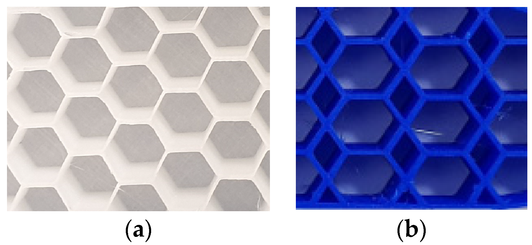
Before we go further, the discussions about homogenous and non-homogenous hybrid honeycomb structures are required, since the flexible pattern is derived from non-homogenous hybrid honeycomb structures. As it is known, homogenous honeycomb structures could be found in nature while non-homogenous hybrid honeycombs are artificially designed for different applications. We are considering non-homogenous hybrid honeycombs which are made of hexagons and rhombs. There are noticeable differences between homogenous and non-homogenous hybrid honeycomb structures in their design and mechanical performances because of their topological differences. The differences in their design can be visually observed from
Figure 1.
The main advantage of non-homogenous hybrid honeycomb structures is that they are lighter than the above shown homogenous honeycombs, which can be noticed from their geometry. The non-homogenous hybrid honeycomb structure consumes less printing material because it consists of a combination of hexagons and rhombs while the homogenous structure comprises only hexagons, the perimeter of the homogenous structures is larger compared to the perimeter of the non-homogenous hybrid honeycomb structure, which can be seen from their design in
Figure 1. The proposed method can create vertically and horizontally positioned patterns using the non-homogenous hybrid honeycomb structure.
The method in the current study was developed to generate soft 3D printed fabrications with highly deformable stability. This uses a combination of tailored 3D fabrication with such physical properties as flexibility and supplementary stretchability, while providing a lightweight interior. This goal was accomplished by developing flexible infill patterns based on non-homogenous hybrid honeycomb structures. The developed patterns are applied to the interior of soft 3D printed fabrications. The flexible honeycomb pattern is constructed according to the designed scheme and its topological part is shown in
Figure 2.
The pattern elements
, where
are generated according with the following subdivision matrix:
The honeycomb patterns are derived from a symmetric grid mesh
with the set of elements
, which consists from the set of points
where
it can be written in the following form as
where n = Z,
and
V can be written as
=
,
.
where
is the subdivision matrix and
is a new set of points.
In the above, we described the pattern construction along with the topological part. Further, we focused on the presented method. With our approach, the interior of a 3D fabrication is decomposed into different regions, where the number of regions depends on the application requirements or the user’s demands.
where
I is the interior area of the object and
P is the number of partitioned regions. Within the region, a certain interval created a column of pattern elements.
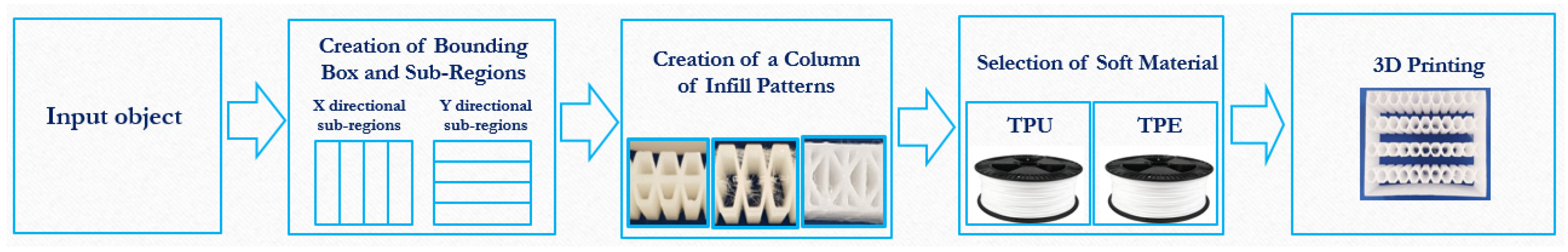
The proposed method was built with accordance of the following block diagram that can be seen from
Figure 3. The diagram shows major stages for processing input models in order to produce objects with the presented interior design and infill patterns.
For each sub-region, the Euclidean distance for each region is calculated as follows:
The regions are symmetric or asymmetric depending on the application requirements and they are equidistant from each other as: where are points.
A column of pattern elements is created for each partitioned region and the presented honeycomb pattern can be position in biaxial directions, as shown in
Figure 4. There are four regions where we created columns of flexible honeycomb patterns. Each column intervals are specified in
Table 1.
In this study, we introduced two types of honeycomb patterns: (1) a regular honeycomb pattern and (2) a honeycomb trapezoid with a slightly distinctive topology, as shown in
Figure 5. For the comparison test we have investigated a standard grid-type pattern.
4. Flexibility of the Honeycomb Pattern
The mechanical properties of honeycomb patterns can be described by analyzing a single honeycomb pattern element. Furthermore, it is necessary to take into consideration its geometrical parameters, since the parameters will change when the element is subjected to compression loads, as was explored in a similar study [
38]. The pattern element along with its geometric parameters are shown in
Figure 6.
We denoted the parameters of the element as follows:
is the height of the side,
is the length of the side, where
is the angle between the horizontal and inclined edges that we consider as
because we are considering a regular hexagonal element. The hexagonal element’s overall width is defined as
and the overall height is
In the current study, it is important to note that H is defined as the full overall height of the element, while in other similar studies—as in the study [
39], based on the homogenous honeycomb structure, used half of the overall height of the honeycomb cell. In our case, the element is fully affected by compression, tension- and flexure loads since the presented flexible pattern is derived from non-homogenous honeycomb. Depending on the strength of the loads, the geometric parameters of the honeycomb pattern will be changed and will be different than its original parameters.
To test the flexibility of the honeycomb pattern, we conducted a simple compression test, which can be observed in
Figure 7.
Figure 7 shows how infill patterns are affected when we apply a y-directional compression load with a pen, which was used for visual observation of the pattern flexibility. The strength of the applied load changes the geometric parameters of the element—hence it becomes
and
during the compression. There are affected areas of the element along the
x and
y axial direction is defined as follows:
where
Ax and
Ay are the affected areas of the element by compression load, b is the depth of the element;
To provide detailed insights for the honeycomb deformation mechanisms we provided a model for biaxial loads, but we practically considered y-directional load in
Figure 7. The element sides are considered as beams. As it is known, the bending moment is the reaction induced in a honeycomb element, which tends to bend the walls of the pattern element when the load is applied. We defined the moment
M on the
x and
y directional beam as follows:
where
Px and
Py are the axial loads;
and
are the bending moments on the
x and
y directional beam;
The loads can be defined from the following equation:
where
σ1 and
σ2 are x and y directional forces;
Here, in the above-mentioned Equation (7), we considered the directional overall height H and the overall length L.
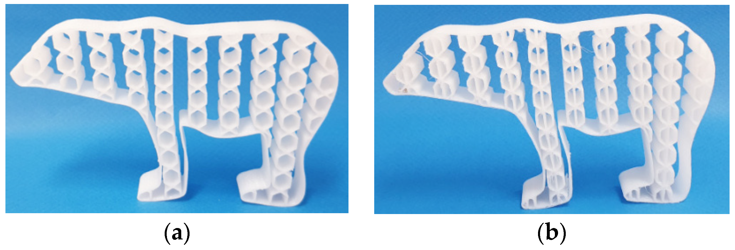
As it is shown in
Figure 7, the pattern elements bend easily because of the elastic properties of the soft 3D printing materials, TPU and TPE, and due to the geometry of the honeycomb patterns.
When the load is removed, the pattern elements return to their original state without permanent deformation due to the flexibility of the patterns and the material’s elasticity.
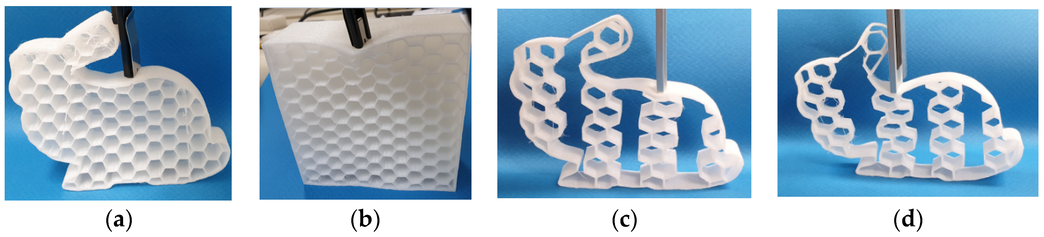
In
Figure 7, the bunny models with larger and medium size patterns can be seen, the models were tested by a pen and metalic stick to visually examine their flexibility. Furthermore, to provide a quantified evidence of the flexibility, the bunny model was tested by the UTM machine INSTRON-5690 (USA, INSTRON). The result showed that its compression strength is more than 1000 N.
In the current study, the built model that determines the flexibility of the honeycomb pattern is different from the majority of the proposed models. Our flexible honeycomb patterns are derived from the non-homogenous honeycombs, and for this reason we considered the full overall height in Young’s moduli as follows:
where
and
are the Young moduli in
x and
y axial directions;
is the applied forces in x and y directions that needed to produce a unit displacement;
is the width of the element along x-direction and
is height of the element along y-direction;
and
are the areas of the element along the x and y directions.
and are the displacements in x and y directions.
Another elastic component, such as
,
, is the Poisons ratio x, and y axial directions can be defined from the following equation:
where
are x and y axial directional strains.
The shear modulus
is defined as follows:
We can conclude that the proposed interior design and the geometry of the patterns, as well as material properties, make our 3D fabrications more flexible. The proposed interior design combines flexibility and low weight, which are valuable physical properties for 3D fabrications. Additionally, we examined the flexibility of samples fully filled with the homogenous honeycomb structures and sparse homogenous honeycombs, as can be seen in
Figure 8.
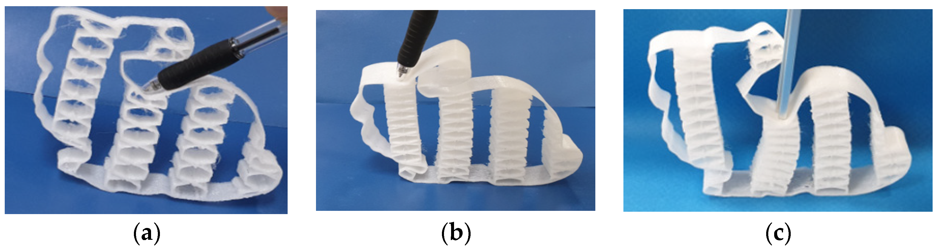
As depicted in
Figure 8, we applied y-directional compression load with a metallic stick, which is heavier than a pen to provide more sufficient compression load for the samples that are fully filled with the homogenous honeycomb structures. Despite the elastic properties of soft 3D printing materials, a very slight bending effect was observed at the top of models. Here, homogenous honeycomb structures are non-orthotropic. The compression strength of the bunny model was only 40N, which backs up the above statement. It is less flexible compared to the bunny model with our proposed interior design and the patterns.
Further, we have experimented with samples that are filled with the sparse honeycomb patterns, as shown in
Figure 8. Here, the pattern is derived from the homogenous honeycomb structure. To determine the flexibility of the samples we carried out a test where the samples were subjected to y-directional compression load with a metallic stick. The metallic stick was used in order to provide a stronger compression load. We observed that it is still less flexible than our proposed honeycomb pattern. However, it was slightly better compared to the samples with fully filled homogenous honeycomb structures. From the current examination, we can conclude that the interior filled with the homogenous honeycomb structures are less flexible compared to our proposed pattern. Moreover, our patterns can be flexible in two directions because they are based on the non-homogenous honeycomb structures, which enables to position the columns of patterns vertically and horizontally with the entire elements by our method.
5. Soft Printing Materials
Thermoplastic polyurethane (TPU)
The mechanical properties of TPU are dependent on its chemical consistency, as we described earlier. We further focused on the hardness scale. The Shore hardness of TPU is important because it is a measurement that describes TPU properties. Generally, the Shore hardness of TPU begins from A to D. The category A denotes a flexible type of TPU, while the category D refers to more rigid TPU, the relationship between categories and the TPU and TPE hardness range is depicted in
Figure 9.
Thermoplastic elastomer (TPE)
Similarly, with TPU, TPE materials have a variety level of flexibility and softness that is determined by its chemical blends. Because of the elastic properties of TPE users can fabricate soft and flexible 3D fabrications, which are also durable. The printing process can be challenging for TPE compared to TPU because of several factors as the printing speed, temperature and settings. To avoid inaccuracy, it is recommended to set the lower printing speed at 5 to 30 mm/s.
As mentioned above, the characteristic of soft 3D printing materials is determined by Shore hardness. This hardness scale allows users to fabricate with a required level of flexibility. The level of flexibility can be determined according to the hardness scale table in
Table 2.
In this study, TPU printed 3D fabrications with the Shore 80 A and TPE printed 3D fabrication with the hardness scale is 60A were used.
6. Experimental Results
As mentioned in the introduction, soft printing materials come in a variety of chemical consistencies and different levels of hardness. Therefore, we printed our outputs with different soft printing materials, such as TPU and TPE, to conduct a comparison test between these outputs to determine the physical properties of 3D fabrications.
Moreover, we consider how the materials impact the flexibility and additionally stretchability of the soft 3D printed fabrications. The mechanical performance of our outputs was measured under compression using the UTM machine INSTRON-5690 (USA, Instron).
Tension test results
The results for the conducted tension test are provided in the
Table 3. We conducted tensile stress tests for different soft printing materials. From the results of our experiment we can conclude that soft 3D printed fabrications are impacted by factors as the pattern type and the material.
The tension experiment showed varying results for TPU and TPE printed samples because of their material properties. The most stretchable sample is a 3D print made of TPE. The current experiment verifies the technical characteristics of TPE and TPU regarding their stretchability.
Compression test results
The experimental test results for the compression test are shown in
Table 4. The compression test was done to reveal the compression strength of our proposed patterns. When a compression load was applied, the linear elastic deformation is occurred by causing the patterns elements to bend.
The results of the test revealed that the compressive strength of a pattern directly depends on the elastic properties of its material, as well as on the geometrical shape of its infill pattern. The experiment verified the flexibility of our patterns where loading conditions were conducive to buckling.
Flexural Test
In
Table 5 has shown the results of flexure test. As it is known from the physics that flexible materials have lower flexural strengths compared to rigid materials; therefore, we have lower flexural strengths for 3D printed models with TPE and the higher strengths for samples with TPU. Besides, the pattern topology impacts their flexural strengths.
Weight comparison
In addition to determining the optimal pattern for flexibility, we have included a weight comparison of the fabricated 3D objects. This part of the experiment allows us to determine the cost-effectiveness of our method. We measured the weight of each presented model to reveal the lightest interior for soft 3D printed fabrications. These results are shown in
Table 6. As it can be seen, there are three different patterns presented with the proposed interior design. The experiment reveals that the lightest model is the fish model with the hexagonal interior, which weighs 47 g. The second lightest is the model with the hexagonal trapezoid interior.
In
Table 6, we also tested homogenous and non-homogenous honeycombs regarding their weights. It is shown that our honeycomb pattern is lighter than the homogenous based honeycomb structure.
In
Table 7, we compared different sizes of the honeycomb pattern with the standard grid pattern. The lightest soft 3D printed fabrication is the bunny model with the weight of 22 g.
In
Table 8 we have done a comparison test for 3D models from different categories. The experiment was carried out by measuring their weight one by one. The lightest interior is the hexagonal pattern. Hexagonal patterns are the most efficient patterns regarding their cost-effectiveness and flexibility including stress-sustainability. Therefore, they are widely used in different applications.


