1. Introduction
Stainless steel insulated mugs are currently popular due to their heat-insulating properties. Such mugs are usually composed of two layers, i.e., inner layer and out layer, between which a vacuum area is kept. One end joint of the two layers forms the mouth seam of the insulated mug. The other end joint of the two layers forms the bottom seam. The two seams need to be welded with high quality to keep the insulation performance. At present, the mouth and bottom seams of the insulated mug are almost welded manually, which is increasingly unable to meet the market demand for the insulated mugs with high quality.
To improve the weld efficiency and quality, new welding technology that is fit for the insulated mug needs to be adopted. Recently, laser welding has been increasingly used in welding for thin plate. It is an efficient and precise welding method using high energy density laser beam as heat source, which has many merits such as small heat affected area, small heat deformation, deep penetration, no need for welding fillers, high welding speed, and so on [
1,
2,
3]. It is very suitable for narrow seams of thin plate like the mouth and bottom seams of the insulated mug. Since the speed of the laser welding is very high, the torch cannot be moved manually. It is should be installed on a robotic system. Meanwhile, to guarantee the weld quality, the laser welding demands that the position of the torch relative with the seam is precise enough. Due to the shape and position differences of the insulated mugs, a seam tracking system needs to be designed to keep the torch precisely on the seam during the welding process.
Welding robots have been widely adopted in industries and have greatly increased the weld efficiency and quality consistency [
4,
5,
6]. To make the welding robots adapt to the position difference of the seams from the robot teaching stage, seam tracking systems have been added to the robots. Several kinds of sensors have been used in the robotic seam tracking systems, such as through-the-arc sensors [
7], inductive sensors [
8], ultrasonic sensors [
9] and vision sensors [
10,
11,
12,
13,
14,
15]. Among these sensors, vision sensors attract the attention of the researchers in the robotics field recently due to their non-contact measurement, rich information and high precision. Some researchers just use a monocular camera as the vision sensor to detect the position of the seam. In [
12,
13], the initial position of the weld seam was located based on template match algorithm using monocular camera. Chen et al. [
14] used a monocular camera to detect the narrow seam in container plate and designed a robust visual servo control method for seam tracking. Some researchers combine the monocular camera with structured laser light as the vision sensor to detect the weld seam. Unlike the former kind of vision sensor, this kind can get three dimensional information of the seam based on triangulation principle. Fang et al. [
15,
16] used a vision sensor with structured laser light to detect the fillet seam and designed a self-tuning fuzzy logic seam tracking control system. Xu et al. [
17] proposed a seam tracking system based on vision sensor with structured laser light to improve the welding quality of robotic gas metal arc welding. In [
18], a seam tracking system based on a vision sensor was designed for welding a thin plate, in which a decoupled visual measurement method was presented at horizontal and vertical directions.
In this paper, a robotic welding system is designed for welding the mouth and bottom seams of the stainless steel insulated mug. To increase the weld efficiency and quality further, laser welding is adopted. Before welding is started, a vision sensor with structured laser light scans the seam and feature sample points are obtained. To get smooth seam trajectory, random sample consensus (RANSAC) algorithm is proposed to eliminate the outlier points and LSF method is applied to the remaining inner points. When the welding is started, seam tracking control system based on fuzzy logic is proposed to keep the torch precisely on the seam. Experiments on the insulated mugs verify the effectiveness of the proposed method.
The main contributions of this paper are as follows. Firstly, vision sensor based on laser structured light is adopted to the robotic welding of the insulated mugs to improve the welding quality greatly. Secondly, a novel image reconstruction algorithm is designed to form the seam image from the sampled points. Thirdly, RANSAC and LSF algorithms are proposed to get the smooth seam from the image.
The rest of this paper is organized as follows.
Section 2 describes the configuration of the robotic welding system for the insulated mugs. In
Section 3, the visual seam extraction based on LSF and RANSAC is given. The detailed presentation of the proposed fuzzy seam tracking control system is given in
Section 4.
Section 5 illustrates the experimental results and
Section 6 concludes this paper.
3. Weld Seam Detection Based on Vision Sensor
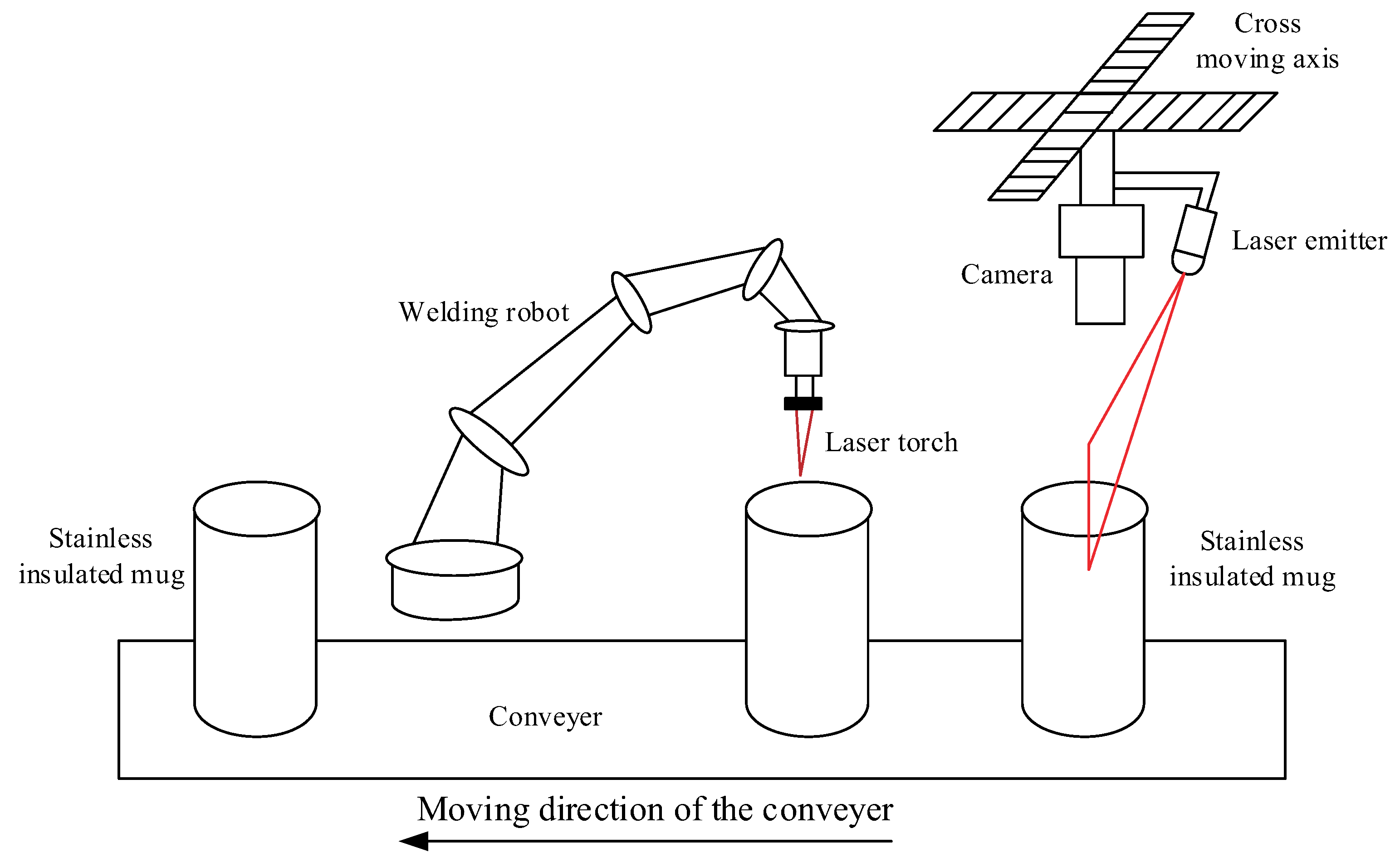
The mouth and bottom seams of the insulated mugs are welded to keep vacuum property of the air between the inner and outer layers. Since the seams are very narrow and the demand for the weld quality is high, laser welding is adopted. This kind of welding technology needs the position of the torch to be precisely controlled. Due to the high speed of the laser welding, the position of the torch can not be controlled manually. In this paper, an automatical robotic welding system with vision-based seam tracking is proposed. Before welding is started, a cross slider moves the vision sensor with laser structured light across the seams of the mugs. Then, the arc is on and the extracted seam position points are used to guide the torch precisely along the seams during the welding process. In the following sections, the principle of the vision measurement for the seams of the insulated mugs and the main procedures of the feature extraction are described.
3.1. The Reconstruction of the Image from the Sampled Points
As shown in
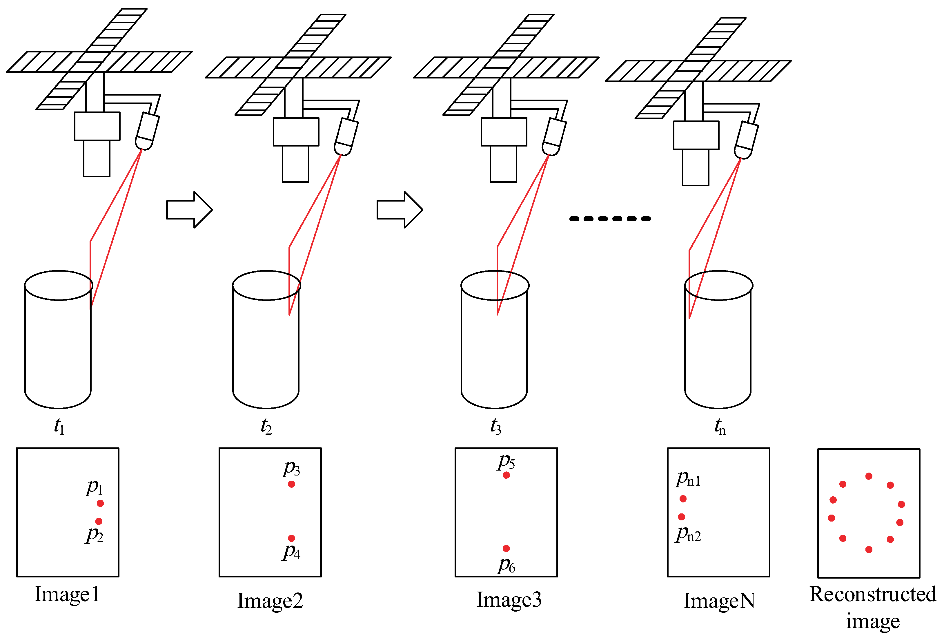
Figure 1, the robotic welding for each insulated mug consists of two stages. Firstly, the vision measurement for the weld seam is completed. Then, the robot finishes the welding along the seam guiding the laser torch. At the first stage, the laser-structured vision sensor scans the seam from the right to the left moved by the cross moving axis. The detailed scanning process is shown in
Figure 2. It can be seen that at each time, only two points can be obtained due to the intersection of the laser plane and the seam. For designing the seam tracking controller, an image containing the whole seam points needs to be reconstructed from the images scanned at each time. The reconstructed image can be described as
where
is the reconstructed image,
is the image scanned at the time
.
3.2. The Computation of the Coordinates of the Seam Points Based on the Vision Sensor
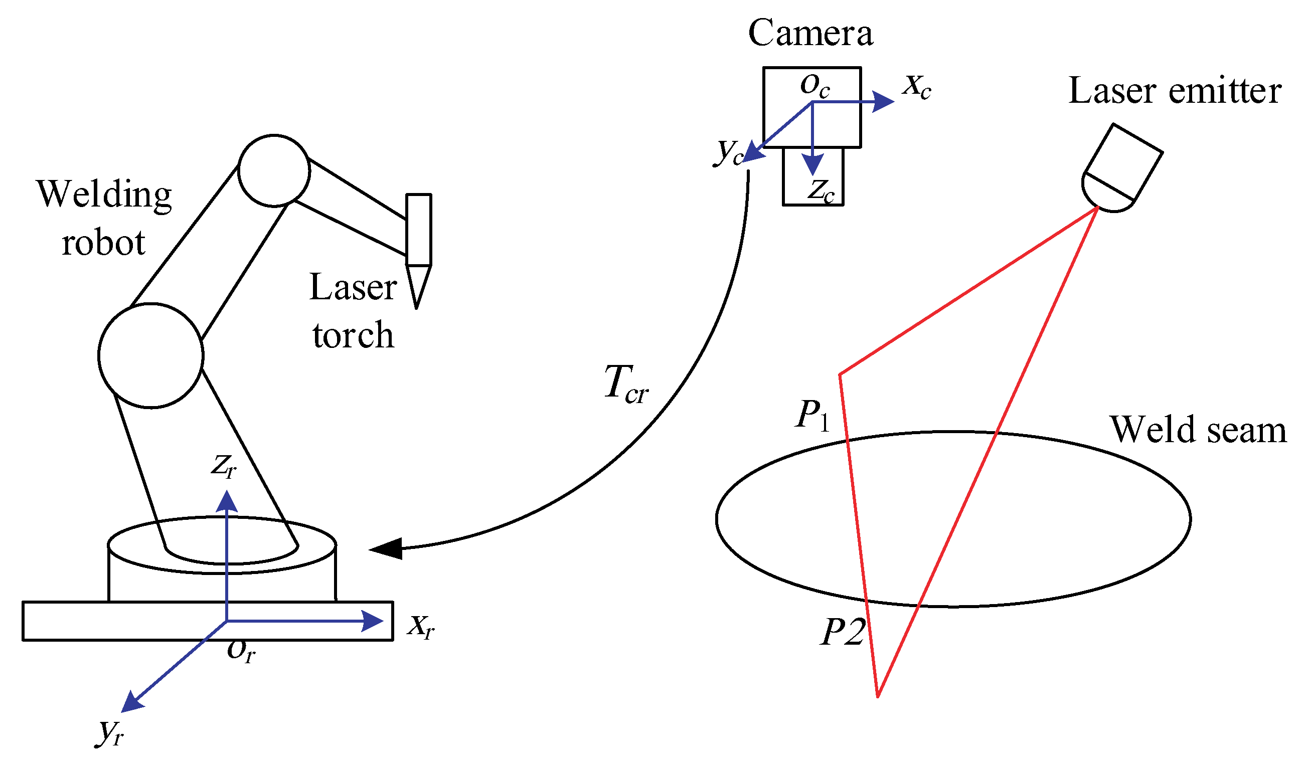
Since depth information of the feature point cannot be obtained with single camera, the vision sensor with a camera and a laser-based light source is used in this paper, as shown in
Figure 3. The computation of the three-dimensional coordinates of the seam points is based on the principle of triangulation.
For the convenience of analysis, two coordinate frames are established. The camera frame C is established at the optical center of the camera. Its x-axis and y-axis are the same as those of the image plane. Its z-axis is accordance with the optical line of the camera. The robot frame R is established at the base center of the robot according to the definition of the robot manufacturer.
Suppose the intersection point of the laser plane emitted by the laser emitter and the seam of the insulated cup is
. From the pinhole model of the camera, the following equation can be given
where
are the coordinates of the point
in the camera frame,
are the corresponding coordinates of the point in the image,
M is the intrinsic matrix of the camera,
and
are the magnification coefficients from the image plane to the image coordinates in
x-axis and
y-axis, respectively,
is the coordinates of the principle point of the camera. The above intrinsic parameters of the camera can be obtained using the camera calibration method [
19].
The seam point
is on the laser plane emitted by the laser emitter, as shown in
Figure 3. Therefore, the following equation can be given
where
a,
b and
c are the parameters of the laser plane, which can be obtained using the laser plane calibration method [
20,
21].
Given the coordinates of the point
in the image, its three-dimensional coordinates in the camera frame can be computed from (
2) and (
3) as follows.
Since the seam tracking control is realized in the robot frame, the seam points in the camera frame as given by (
4) need to be transformed to the robot frame as follows.
where
are the coordinates of the seam point
in the robot frame,
is the transformation matrix from the camera frame to the robot frame, which can be calibrated using the
method [
22].
3.3. Circle Seam Detection Based on LSF and Visual Points
Due to the light reflection of the stainless steel of the mugs and the moving influence of the cross slider, the captured seam position points may contain lots of noise. If the seam data is directly used to the seam tracking system, the torch may tremble abruptly and the welding quality can not be guaranteed. Since the seams to be welded are the mouth and bottom of the mug, the seam shape is a circle in 3D space. To detect the smooth circle seam in 3D space, this paper firstly extract the circle seam based on LSF method using the seam position data from the vision sensor. Then, RANSAC algorithm is used to eliminate the outlier points and the precise circle seam is detected using the remaining inner points based on the LSF again.
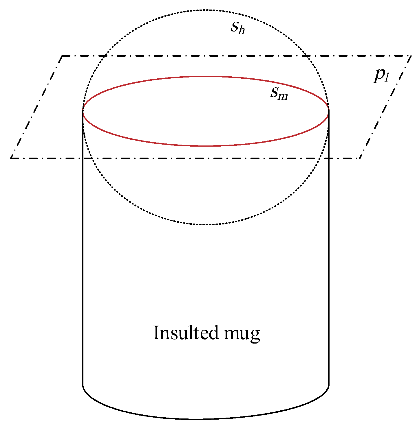
After the vision sensor with laser structured light scans the mouth and bottom seams of the insulated mug, some discrete visual points are obtained. To detect the circle seam in 3D space from the visual points, LSF method is proposed. The circle in 3D space can be considered as the intersection of a plane and a sphere. As shown in
Figure 4,
is the plane fitted based on the visual seam points,
is the fitted sphere,
is the extracted mouth or bottom seam. Therefore, to detect the mouth and bottom seams, the plane and sphere should be firstly extracted based on the visual seam points. The plane in 3D space can be described by
where
a,
b and
c are the parameters of the plane.
We can assume that the visual points lie on the same plane. If there are
n points extracted from the vision sensor, the following equation can be given
where
are the visual points,
are the parameters of the plane. According to the LSF method,
can be computed by
At the same time, the visual points lie on the same sphere. The sphere in 3D space is described by
where
is the center of the sphere,
r is the radius of the sphere.
Based on the indirect adjustment model [
23], the following model can be given
where
From (
10), we can get
where
P is the identity matrix of order
n. After
is determined, the center
and radius
r of the sphere can be computed.
The circle seams of the mouth and bottom of the mug is the intersection of the plane and the sphere. Therefore, from (
8) and (
13), the parameters of the circle seams can be computed.
3.4. Precision Improvement for the Detected Circle Seams
Due to the light reflection of the stainless steel of the mugs or the moving influence of the cross slider, the captured visual points do not all lie on the real circle seams. Some points are may far away from the circle seams. We name these points as outer points. Other points are very close to the circle seams. We name these points as inner points. If all the captured visual points are used to detect the circle seams, the precision can not be guaranteed. However, if the outlier points are firstly eliminated and the remaining inner points are used to detect the circle seams, the precision can be greatly improved. In this paper, RANSAC is used to eliminate the outlier points. Then the circle seams are detected based on the remaining inner points. The flow path of the circle seam detection algorithm based on LSF and RANSAC is shown in Algorithm 1.
| Algorithm 1 Circle seam detection based on LSF and RANSAC |
Input: Sample points captured from the vision sensor |
Output: Plane parameters and sphere parameters |
- 1:
Initialization of the iteration number , the biggest iteration number , the number of sample points for the plane and sphere fitting, the distance threshold value , the inner points set with size , the outlier points set , the inner points set with biggest size . - 2:
whiledo - 3:
Randomly select sample points - 4:
Compute and based on LSF method and the sample points using ( 8) and ( 13) - 5:
Compute the distance from the sample points to the center of the fitted circle - 6:
The sample points with distance smaller than are put to the inner points set , the ones with distance bigger than are put to the outlier points set . - 7:
Compute the size of the inner points set - 8:
if then - 9:
- 10:
- 11:
Compute and based on LSF method and the inner points set using ( 8) and ( 13) - 12:
return The plane parameters and the sphere parameters
|
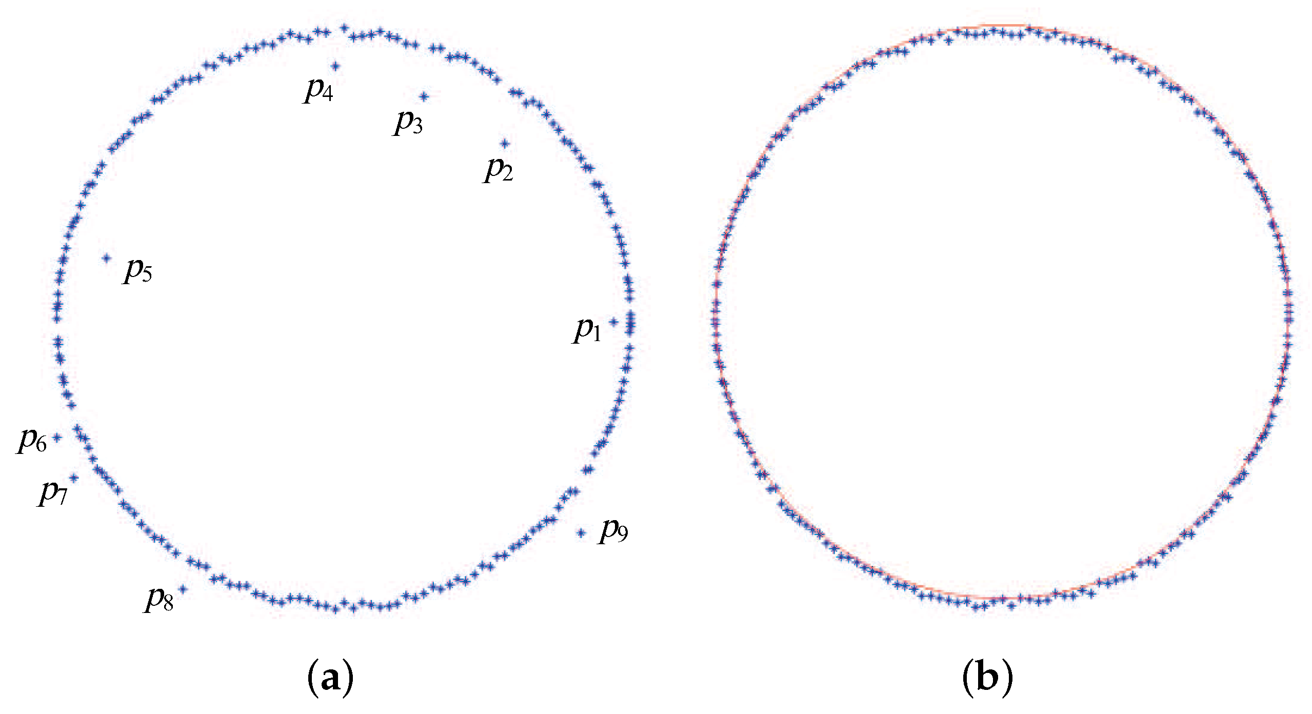
The results of the circle seam detection is shown in
Figure 5.
Figure 5a shows the reconstructed image contains several outlier points such as
to
. After the processing of the new RANSAC algorithm, the outlier points are removed from the image as shown in
Figure 5b. The red circle line in
Figure 5b is the final detected seam of the mug. It can be seen that the seam is well detected and smooth enough.
4. Fuzzy Seam Tracking Control
The laser welding needs the position of the torch to be precisely controlled in the welding process. Since the traditional PID controller has disadvantages in the control accuracy and dynamic response speed, it cannot adapt to the seam tracking in the laser welding with high speed. Some researchers have designed intelligent controllers in aerodynamic or urban traffic systems [
24,
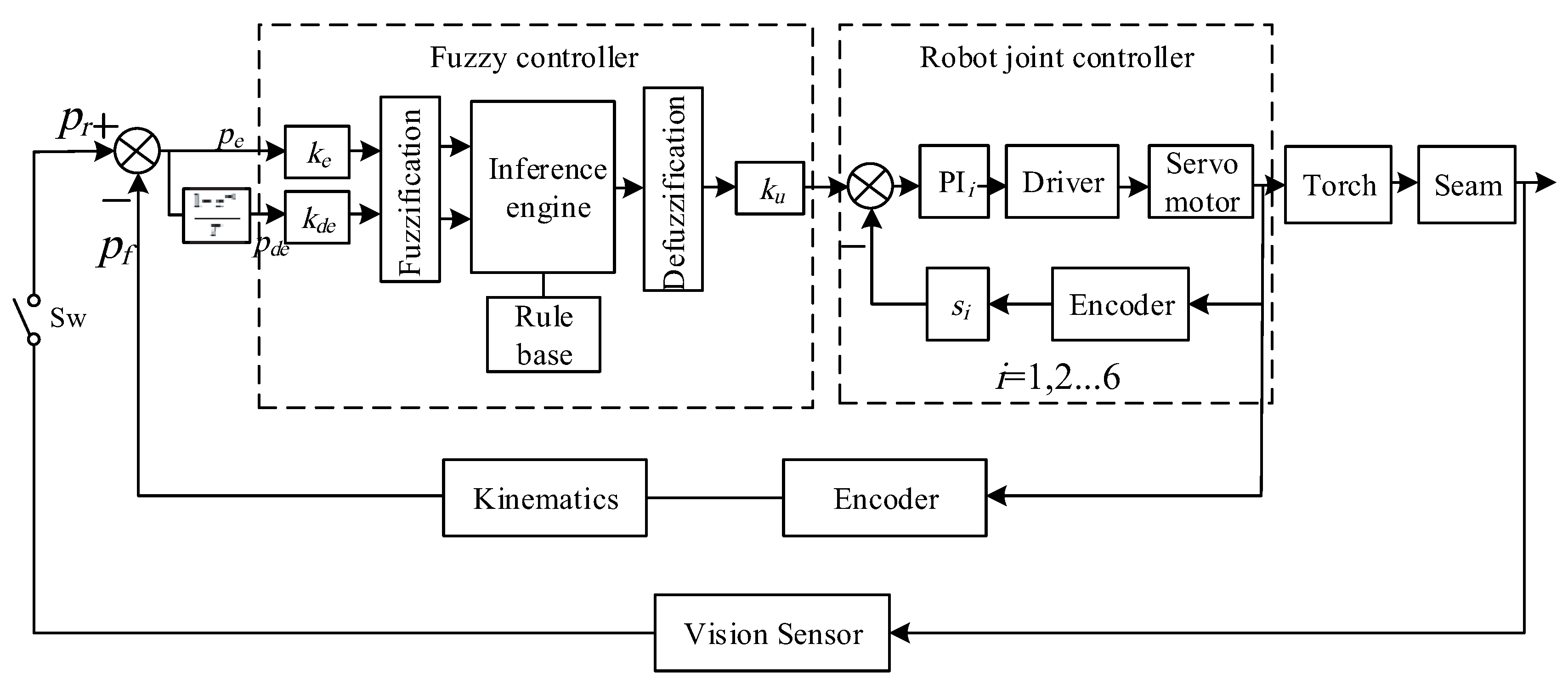
25]. In this paper, fuzzy logic control method is adopt in the seam tracking since it can absorb the intelligence of the welding workers in the adjusting of the torch position through the rule base. The proposed fuzzy seam tracking control diagram of the laser welding for the insulated mugs is shown in
Figure 6. It mainly consists of four parts, i.e., the reference seam position, the torch position feedback, the fuzzy controller and the robot joint controller. The reference seam position is computed based on the vision sensor. It is used as the reference signal of the closed loop control. The torch position is used as the feedback signal of the closed loop control. It is computed based on the robot joint encoders and the kinematics. The fuzzy controller computes the adjusting values of the end effector of the robot based on the errors and difference errors between the reference and feedback signals. The robot joint controllers controls the six joints based on the position of its end effector and robot inverse kinematics. In the following parts, the main parts of the fuzzy seam tracking control are described.
4.1. The Reference Seam Position
The robotic laser welding for insulated mugs is composed of two stages, i.e., the stage of the computation of the reference seam position and the welding stage. At the first stage, the seam is scanned by a laser-based vision sensor and the image features of the seam are extracted. The processed seam position from vision sensor is used as the reference signals of the closed loop control. At the second stage, the robot guides the torch to the mug seam and the arc is on. During the welding process, the torch is kept precisely along the seam by means of seam tracking control.
Since laser welding speed is high and the seam is short, the visual detection for the seam and the laser welding cannot execute simultaneously. Therefore, a switch denoted as
in
Figure 6 is used to divide the two stages. At the first stage, the switch is closed and the reference seam position is computed. Then, at the second stage, the switch is opened and the visual detection is stopped. The closed loop seam tracking control is kept on during the second stage.
4.2. Membership Functions
The inputs of the fuzzy controller are the error and the error change between the reference seam position and the feedback position of the robot end effector as follows.
where
and
are the error and the error change at the sample time
t, respectively,
and
are the reference seam position and the feedback position of the robot end effector, respectively.
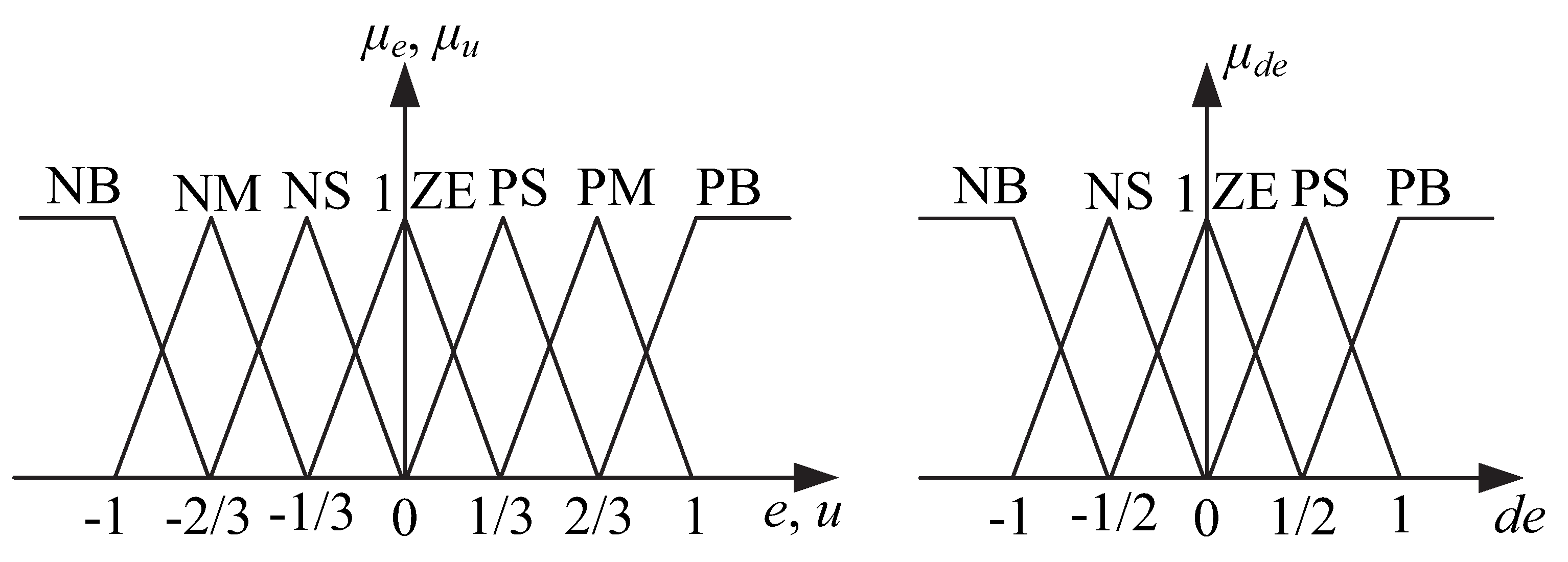
Figure 7 gives the membership functions for the inputs and the output of the fuzzy controller. Seven fuzzy sets denoted as NB, NM, NS, ZE, PS, PM, PB are defined for the input
e and the output
u. The meanings of the seven fuzzy sets are as follows: NB is negative big, NM is negative middle, NS is negative small, ZE is zero, PS is positive small, PM is positive middle, PB is positive big. Five fuzzy sets denoted as NB, NS, ZE, PS, PB are defined for the input
.
Input and output scaling factors are used to make the universes of discourse for the inputs and output lie in the range [−1,1].
4.3. Rule Base
Compared to the traditional controller such as the PID controller, the fuzzy controller can reflect the intelligence of the welding workers to a great extent. Through the rule base of the fuzzy controller, the welding experience of the workers can be recorded as each control rule. In this paper, the rule base is established based on the deep communication between the authors and the welding workers and the authors’ understanding of the robotic laser welding system and by trial and error. The rule base of the fuzzy controller is shown in
Table 1.
Each rule in the rule base has the IF-THEN form. Thus, the
k-th rule can be formulated as
where
,
and
are the fuzzy sets for the
e,
and
u, respectively.
In establishing the rule base, two fundamental principles are to be followed.
(1) When the input error of the controller is large enough, the output of the controller should quickly remove the error. For example, if e is NB and is NB, then u is PB.
(2) When the input error of the controller is quickly reducing, the output of the controller should reduce accordingly to avoid much overshoot. For example, if e is NB and is PB, then u is ZE.
4.4. Defuzzification
The commonly used center of gravity method widely used in the fuzzy field is adopted as the defuzzification method given by
where
u is the crisp output of the fuzzy controller,
is the center of the membership function of the fuzzy set
,
is the membership value of the implied fuzzy set
k of the
k rule, which is computed with the Max-Min inference method.
4.5. Output Verification
The deviation of the torch from the seam must lie in a small range due to the fixing function of the fixture for the mugs and the limited shape difference of the mugs. Therefore, to guarantee the reliability of the seam tracking control system, the output of the controller at each sample time and the total output during the welding process for each mug must be confined to a specific range. Thus, as an example, the output of the controller at the
x direction is given as follows.
where
is the output of the controller at the
x direction at each sample time,
is the total output of the controller for welding each mug,
and
are the output threshold values at each sample time and the whole welding process, respectively.
5. Experiments and Results
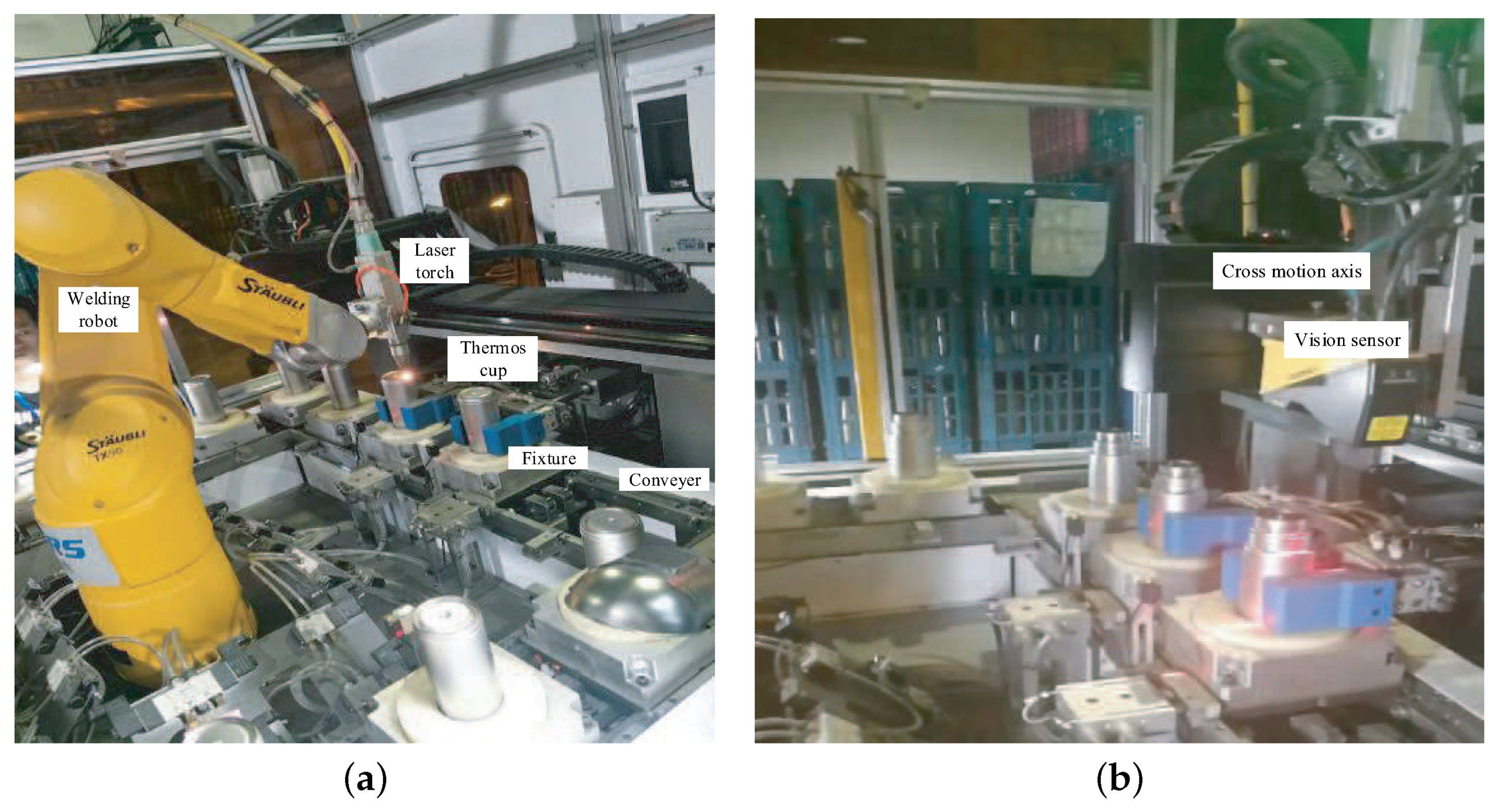
To test the effectiveness of the proposed robotic laser welding system for insulated mugs, experiments are well conducted. The experimental setup is shown in
Figure 8. The industrial robot was
TX90, whose degrees of freedom was 6, load was 20 kg, arm exhibition was 1000 m, repositioning precision was 0.03 mm. Cognex DS1050 was used as the three dimensional vision sensor. Nlight QL-CW1200 was used the laser welding power source. The programmable logic controller (PLC) Mitsubishi FX3U-80MT/ES-A was used as the main controller.
The parameters used in the visual feature extraction for the seam were as follows: , , mm. The image processing costed about 20 ms. Therefore, the parameters in the control system design were set as follows: the sample time was set 50 ms, mm, mm.
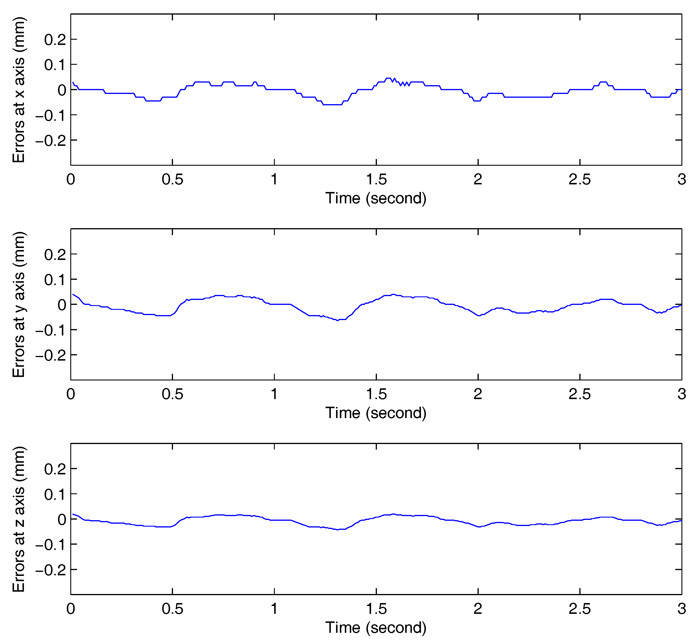
The seam tracking results are shown in
Figure 9, which demonstrates the seam tracking errors in the
x,
y and
z directions, respectively. The biggest tracking error at the
x direction was 0.07 mm, and the mean error was 0.04 mm. The biggest tracking error at the
y direction was 0.08 mm, and the mean error was 0.03 mm. The biggest tracking error at the
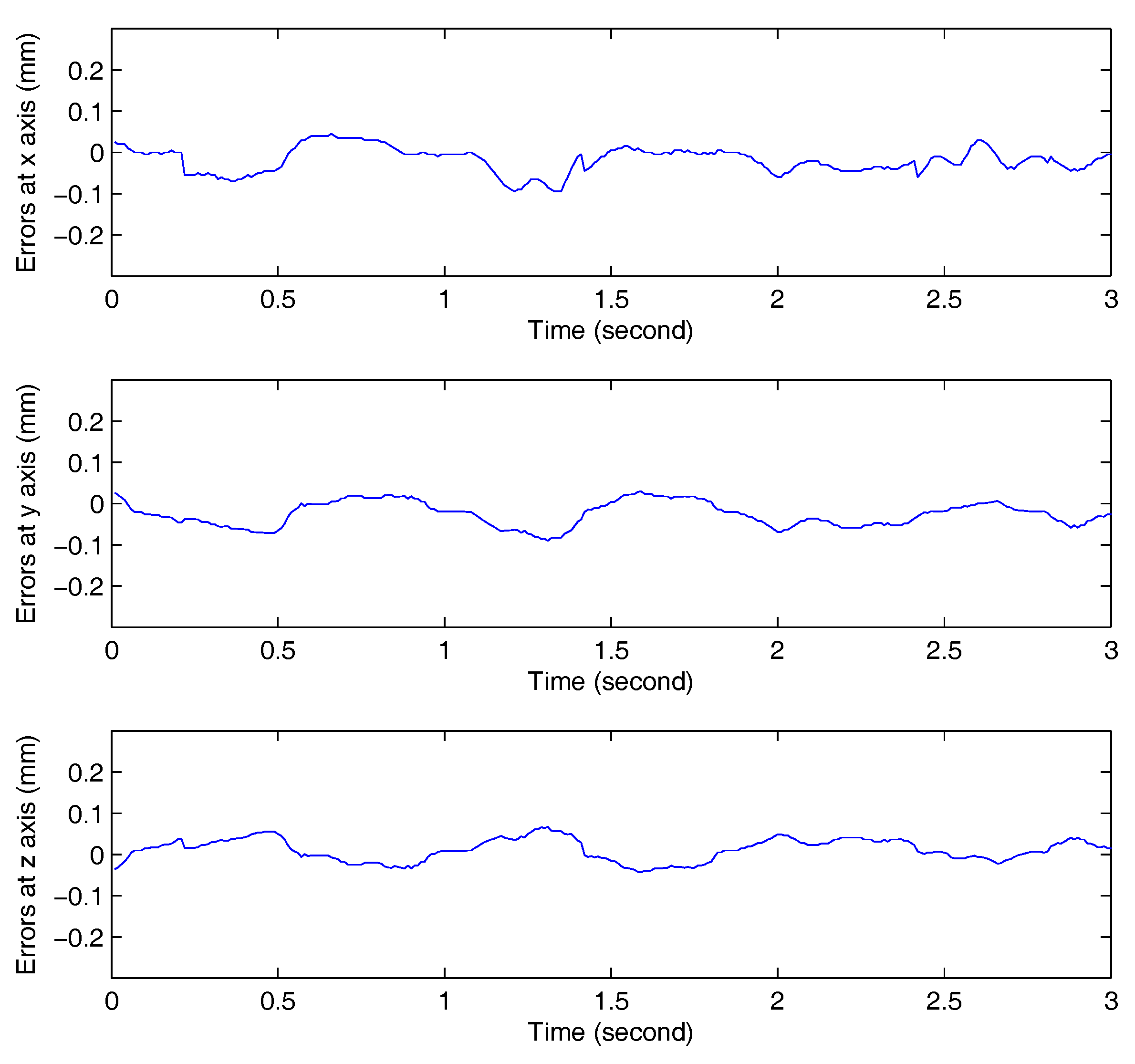
z direction was 0.04 mm, and the mean error was 0.01 mm. From the seam tracking results, it can be seen that high seam tracking precision was achieved using the proposed vision measurement and seam tracking control method. To better demonstrate the performance of the proposed controller, traditional PID controller was used in the comparative experiment. The seam tracking errors with the traditional PID controller are shown in
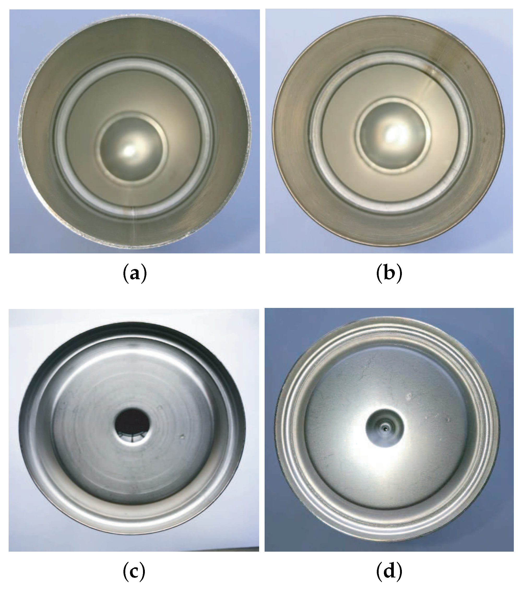
Figure 10. It can be seen clearly that the performance of the proposed fuzzy controller is better than the traditional PID controller. The welded seams of the insulated mugs are shown in
Figure 11.
Figure 11a,b show the welded mouth seams of the insulated mugs, and
Figure 11c,d show the welded bottom seams of the insulated mugs. It can be seen that the high weld quality can be achieved using the proposed robotic laser welding system and the methods described above.
6. Conclusions
A robotic laser welding system is presented for stainless steel insulated mugs. Since the mouth and bottom seams of the insulated mugs are very narrow, the position of the laser torch needs to be controlled accurately to guarantee the weld quality. Therefore, a vision sensor with laser structured light is used to detect the seam features which are used to guide the laser torch. After the seam feature points are obtained using the vision sensor, RANSAC is used to eliminate the outlier points and keep the inner points. Then, LSF method is applied to the remaining inner points to get the smooth circle seam. In the welding process, a vision-based fuzzy seam tracking control system is designed to keep the precision of the position of the laser torch. Experiments are well conducted in the manufacturing factory of the insulated mugs to verify the effectiveness of the proposed robotic laser welding system and methods. The new system and methods can effectively improve the weld efficiency and quality for the insulated mugs.
The disadvantage of the current robotic welding system is that the parameters of the fuzzy controller rely on the authors’ understanding of the system and are defined by trial and error. In the future, the data-driven method may be able to be adopted according to the definition of the parameters of the fuzzy controller. Moreover, some self-tuning methods can be designed for the fuzzy controller to improve the performance further.


