Angle Tracking Observer with Improved Accuracy for Resolver-to-Digital Conversion


School of Instrumentation and Optoelectronic Engineering, Beihang University, Beijing 100191, China
*
Author to whom correspondence should be addressed.
Symmetry 2019, 11(11), 1347; https://doi.org/10.3390/sym11111347
Submission received: 11 October 2019
/
Revised: 28 October 2019
/
Accepted: 29 October 2019
/
Published: 1 November 2019
(This article belongs to the Special Issue Symmetry in Engineering Sciences II)
Abstract
:A resolver is an absolute shaft sensor which outputs pair signals with ortho-symmetric amplitudes. Ideally, they are sinusoidal and cosinusoidal functions of the shaft angle. In order to demodulate angular position and velocity from resolver signals, resolver-to-digital conversion (RDC) is necessary. In software-based RDC, most algorithms mainly employ a phase-locked loop (PLL)-based angle tracking observer (ATO) to form a type-II system. PLL can track the detected angle by regulating the phase error from the phase detector which depends on the feature of orthogonal symmetry in the resolver outputs. However, a type-II system will result in either steady-state errors or cumulative errors in the estimation of angular position with constant accelerations. Although type-III ATOs can suppress these errors, they are still vulnerable to high-order acceleration signals. In this paper, an improved PLL-based ATO with a compensation model is proposed. By using dynamic compensation, the proposed ATO becomes a type-IV system and can reduce position estimation errors for high-order acceleration signals. In addition, the parameters of ATO can be tuned according to the bandwidth, noise level and capability of error suppression. Simulation and experimental results demonstrate the effectiveness of the proposed method.
1. Introduction
Accurate estimation of angular position and velocity for motor drives is a desired feature in high-performance automatic control systems. Resolvers, due to their strong robustness, high ruggedness and relatively low cost, have been widely chosen as shaft sensors to provide precise position information. However, the output of a resolver is two modulated analog signals which need to be demodulated by adopting resolver-to-digital conversion (RDC) before the angular position can be obtained.
The solutions to RDC are mainly comprised of hardware-based RDC and software-based RDC [1]. The hardware-based RDC method mainly employs a special integrated circuit (IC) [2,3]. However, since the high-precision demodulation chip is expensive and limited by the bandwidth and temperature drift of the hardware itself (external resistances and capacitances), the use of hardware-based RDC may cause deviations, thereby affecting the measurement accuracy of the angle measuring system.
Software-based RDC can solve the problems that hardware RDC faces. A commonly used software RDC method includes open-loop arctangent method with look-up table [4] and type-II angle tracking observer (ATO)-based on phase-locked loop (PLL) technique. The arctangent method calculates the angle position by inverse arctangent operation using the sine and cosine values with a fast-dynamic response [5] and less hardware resources. However, this method is susceptible to electromagnetic noise and also introduces great nonlinearity in the system [2,5].
Therefore, most commercially available close-loop converters employ PLL technique to overcome noise and achieve tracking the input position signal with high resolution and wide bandwidth. A conventional PLL-based ATO consists of a phase detector, a loop filter (LF) and a voltage-controlled oscillator. The sinusoidal phase detector is used to generate the estimated error, which is proportional to the difference between the input signal and output signal. Then the error signal goes into a low-pass filter to remove high frequency noise. To complete the loop, the voltage-controlled oscillator works as an integrator for the filtered signal. It is important to note that the form of LF is (kP + kI/s), which makes the conventional ATO a type-II system.
In order to improve the performance of conventional ATOs, modifications have been made over the past years. Some ATOs aim to reduce impact of disturbances in analog signals from the resolver [6,7], and thus on the estimated angular position. Sivappagari and Konduru proposed an ATO that utilizes synchronous demodulation of the input signals and reference signal to enhance the precision of position determination [8]. As for the application in sensorless drives, ATO is employed for reducing noise and oscillation in rotor position estimation, compared to those obtained from traditional methods [9,10]. Several works [11,12,13,14,15] have focused on solving the amplitude imbalance-induced position error with modified ATO algorithms for error compensation.
Regarding the instability of ATO in high acceleration applications, a hybrid ATO scheme incorporating an LTI observer and a quadrature encoder was proposed [7]. This hybrid method has a low mean square error and can improve robust stability. Low dynamic response has been investigated by Yim et al. [16], where the conventional proportional-integral (PI)-based LF was transformed into a “bang-hang”-type phase comparator for fast tracking capability.
Another limitation of the conventional ATO is that it will cause a steady-state error with a speeding up signal at a constant acceleration. To reduce this error, several PLLs based on the third-order tracking loop have emerged [17,18,19,20]. Li and Wu [2] transformed the conventional type-II ATO system into type-III by changing the low-pass PI filter to an improved proportional–integral–derivative (PID) structure, which enhances the ability to filter high-frequency noise components. Also, Wang et al. [5] designed an error compensation module to eliminate this position error by using the estimated speed to generate a signal proportional to the motor acceleration. The advantages of this approach are its simple implementation and time-saving feature since it only requires one module to be added. Ellis and Krah [19] took advantage of the Luenberger observer for angle tracking, which provides estimations of acceleration signals. Their design actually can also be classified as a type-III system in which the LF is represented as (kP + kI/s + kD/s2) [20]. Caruso et al. [21] focused on the compensation of position error by making the tracking system have a time-dependent error, which would finally be cancelled by the PI controller. Zhang et al. [22] proposed a composite observer for fast-varying speed using the arctangent method to compensate the estimated speed from ATO. Drawing on advantages from both arctangent and ATO methods, this composite observer enhances accuracy in estimating acceleration-related position. Neural networks have also been applied independently [23] and combined with third-order ATO [18] for reducing position errors, but the implementation is complicated and time-consuming.
However, there are still limited researches on reducing estimated position errors when the motor speeds up with a non-constant acceleration. Jerk and high-order acceleration are involved in some servo systems requiring high mobility, for example, CNC machining for irregular shape and positioning radar in tracking artillery, which places a great demand for ATO method in precise position estimation with high-order acceleration signals.
Therefore, in this paper, we focus mainly on suppressing steady-state errors for input signals with a high-order acceleration and enhancing the accuracy of ATO. The proposed ATO scheme utilizes the estimated speed signal and a compensation feedback loop to form a type-IV system. Simulation and experiments have been carried out to verify the effectiveness of our scheme. These results demonstrate that not only can errors from low-order acceleration signal be eliminated, but also tracking accuracy for high-order signal can be improved.
2. Principles of Resolver-to-Digital Conversion
In this section we first introduce the basic principle of the resolver and its subsequent demodulation methods, and then several previous RDC solutions are presented and evaluated for their advantages and drawbacks.
2.1. Principle of Resolver
A resolver is a position sensor comprising of a stator and a rotor, which is connected to the shaft of the motor for detecting its angular position. The stator portion houses three windings, namely one excitation winding and two output windings (sine and cosine windings), of which the voltage output amplitudes are orthogonally symmetric, specifically, sinusoidally and cosinusoidally related to the shaft angle. The excitation winding is responsible for inducing voltage in the rotator windings through electromagnetic induction. With the shaft angle changing, amplitudes of the two-phase voltages from sine and cosine output windings are measured and employed to determine relative position between the stator and rotor.
Figure 1 illustrates the configuration of a resolver and subsequent software-based RDC scheme, which serves as an integrated position estimation system. The excitation windings are usually applied with a sinusoidal reference voltage of constant amplitude and high frequency, expressed as:
where A is the amplitude of the reference voltage and ωref is the angular frequency.
When the rotor rotates, the output windings will generate amplitude-modulated pair signals as:
where K is the effective transformation ratio of the resolver and θ represents the angular position of the rotor with respect to the stator winding. These two modulated signals u1(θ,t) and u2(θ,t) have the form of sinusoidal and cosinusoidal envelopes. Then, envelope detection is necessary to obtain the needed signal. In practice, there are always disturbances from imperfect characteristics, namely the amplitude imbalances, DC offsets and imperfect quadrature, which arise from eccentric rotor, unequal winding and non-orthogonal symmetry of the windings. Hence, the signal after envelope detection can be expressed in the form:
where and are the offsets, and represents the imperfect quadrature. Preprocessing methods (noise reduction, calibration and correction) are carried out to result in:
where usin and ucos are two ortho-symmetric signals, whose trigonometric features aid in subsequent demodulation.
Finally, the angular position θ and velocity are calculated through suitable demodulation algorithms (for example, phase-locked loop and arctangent algorithms) to obtain the estimation speed and position .
As is demonstrated in the resolver’s principle, the orthogonal symmetry of alignment of two output windings results in the orthogonal symmetry of both envelope signals and post-envelope-detection signals.
2.2. Classical Resolver-to-Digital Conversion
2.2.1. Arctangent Method
A straightforward method is to obtain the angular position θ is through arctangent operation of usin and ucos, given by:
As is clearly indicated by Equation (5), the arctangent method suffers from its highly nonlinear arctangent operation and is limited to application on low-speed estimation. Also, with a nonlinear feature, there needs to be a look-up table for the arctangent calculation, which increases the software loads.
2.2.2. Conventional PLL-Based ATO
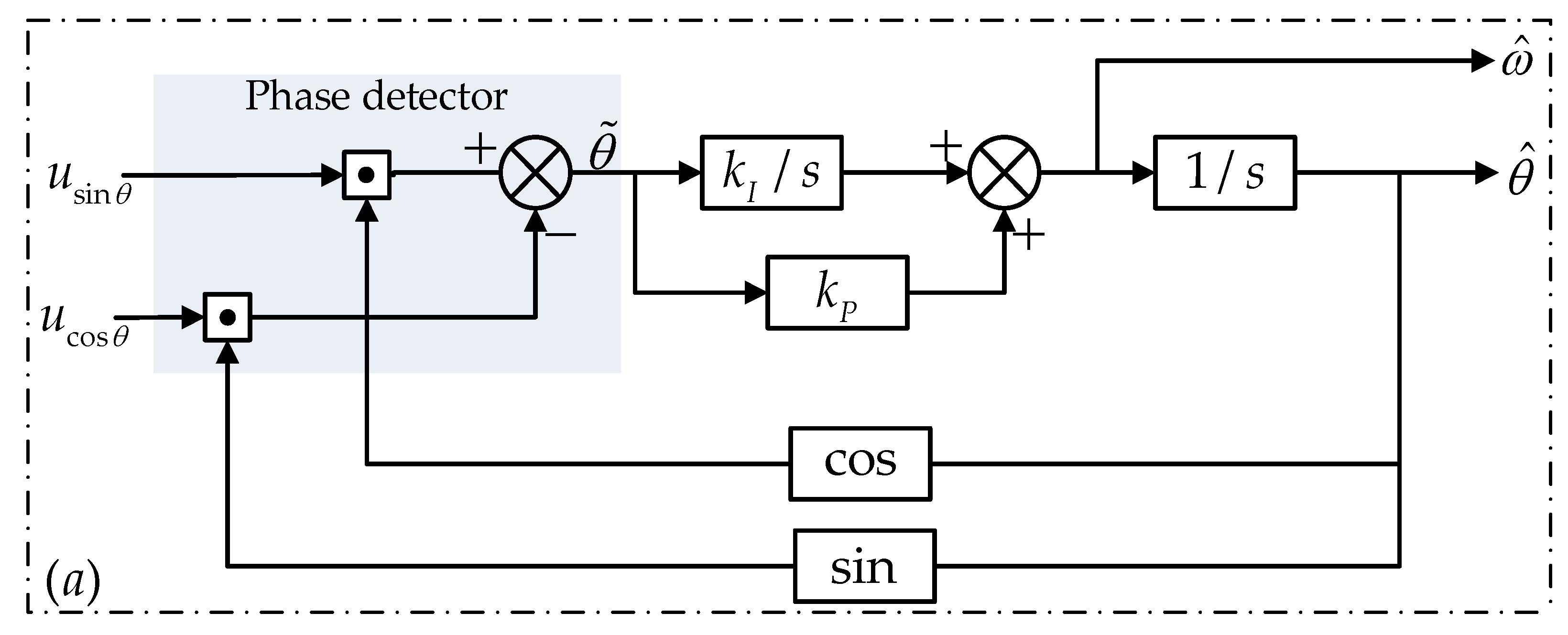
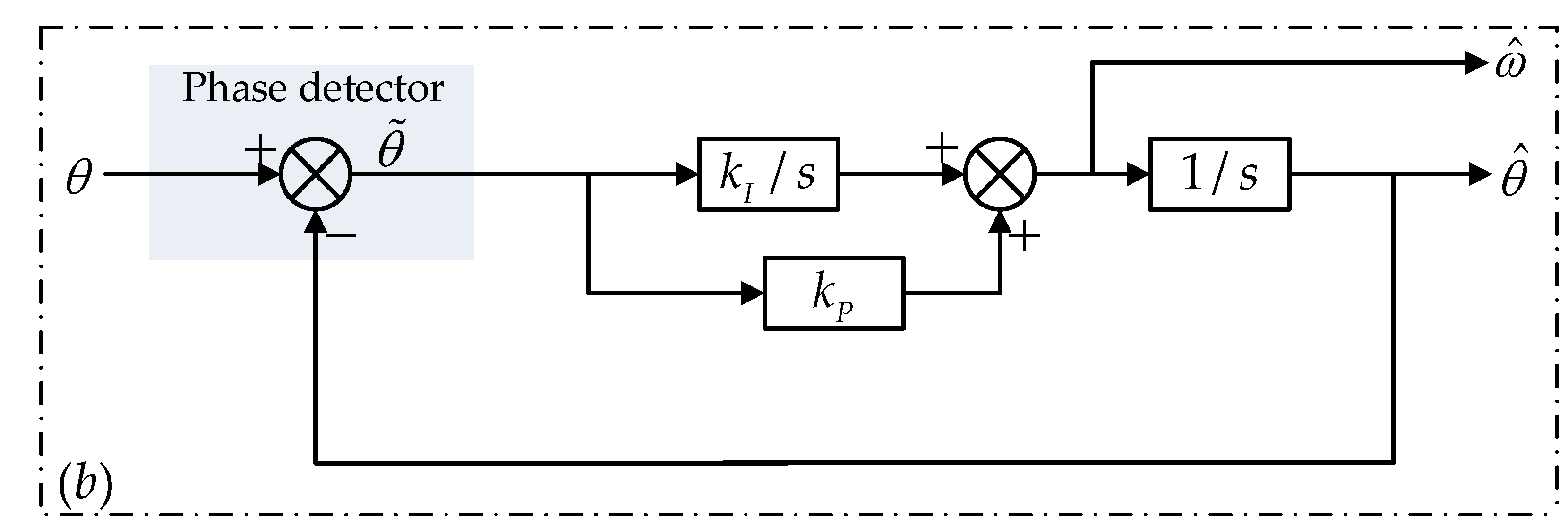
As shown in Figure 2, the conventional ATO method tracks angular position based on PLL technique. Figure 2a is the actual form of the ATO, where kI and kP are the coefficients for the integral and proportional terms, respectively, and Figure 2b shows the linearized structure.
The estimated angular position is transformed through trigonometric function and multiplied by the demodulated signals. By utilizing the feature of orthogonal symmetry in the resolver signals in Equation (4), the phase error can be derived from the phase detector (PD), expressed as:
When the ATO functions properly, the position error is small enough, that is, , so the input error signal can be expressed as . Therefore, linearization of the ATO can be implemented, as shown in Figure 2b, and the closed loop transfer function is derived as:
The conventional ATO is a representative closed-loop estimation system which overcomes noise and track the input signal with a relatively high precision. The linearized structure of the ATO belongs to a type-II system.
2.2.3. Compensated Type-III ATO
In [5], an acceleration-compensated ATO was proposed by employing the estimated speed to generate a compensation module for the position error, comprising a differentiator and a first-order low-pass filter, which finally makes this ATO a type-III system. The actual scheme of this method is shown in Figure 3 and a linearized structure of this ATO is analogous to Figure 2b. Compared with Figure 2, there is a third parameter T representing the time constant of the low-pass filter.
The linearized closed-loop transfer function can be denoted as:
This compensated type-III ATO has the basic structure inherited from the conventional ATO but resolves the steady-error of estimating constant acceleration signal (θ = αt2) with a time-saving and simple technique of adding a compensation module, which achieves a higher precision in tracking the position of an accelerating motor. However, this method fails to eliminate steady-state error resulting from a first- or higher-order acceleration signal.
3. Improved ATO with Dynamic Compensation
Enhanced position estimation accuracy for high-order acceleration signals holds significance and valuable for practical applications in high-precision CNC machines and positioning radar for tracking artillery or other flying targets with high mobility. Although type-III ATO presents a solution to constant acceleration signals, accurately estimating non-constant high-order acceleration signals is still a hard case. To reduce demodulation errors for high-order acceleration signals, a compensated ATO with improved accuracy is proposed in this section. The proposed scheme investigates the error problem and improves the accuracy from the perspective of the internal body of the ATO, which is cost-effective and efficient. Theoretical analysis, simulation and experiments are conducted subsequently to demonstrate the effectiveness of this method.
3.1. Proposed Compensated Scheme of ATO
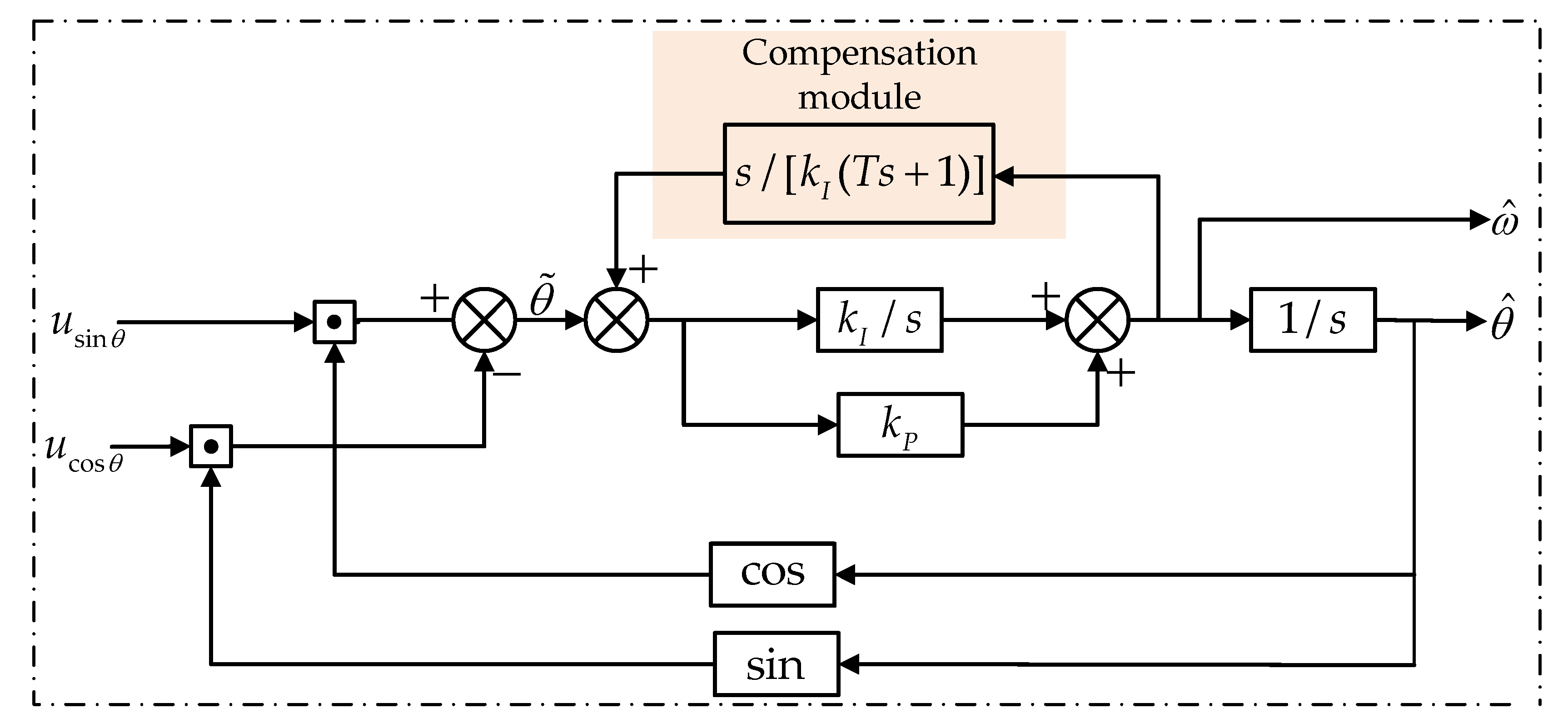
Figure 4 presents the proposed PLL-based ATO with compensation module that inhibits the steady-state error when applying a first-order acceleration signal (θ = αt3). The estimated speed signal is employed to construct an internal feedback loop. The basic idea of the proposed ATO is to improve the system order of the LF and therefore make the ATO become a type-IV system. By carefully designing the parameters and form of the transfer function, low-order items in the numerator of the system transfer function can be cancelled, leaving only the highest-order item, as is illustrated in the following derivation.
In contrast with the abovementioned compensated type-III ATO, the proposed structure takes advantage of a second-order compensation module , where γ is a parameter independent from kI and kP.
Hence, the closed-loop transfer function can be expressed as:
According to Equation (9), it is easy to derive the error transfer function of Figure 4 as:
As for a first-order acceleration signal, , the Laplace transfer is:
By applying the final value theorem, the steady-state position estimation error can be calculated from Equations (10) and (11) as:
The result from Equation (12) indicates that the proposed RDC
scheme can track a signal of no higher than third order regarding time without
error, which greatly enhances the precision for measuring the motor’s position.
While the acceleration order is second, the position steady-state error is a constant value with a dependence of Equation (13):
Although this ATO is still vulnerable to higher-order signal, second-order acceleration and below signals are more common in practical application. Also, according to the Taylor series expansion, even if the signal contains fourth or above components, it is too small to affect the estimation precision.
Theorical analysis shows that the proposed ATO is capable of improving position measurement accuracy by reducing estimation error from high-order acceleration signal, θ = αtn. To be specific, this ATO can eliminate position errors when n ≤ 3 and reduce error when n ≥ 4.
3.2. Parameter Tuning Guidance
In the proposed ATO structure, there are three free parameters for users to tune, namely kI and kP, the coefficients for the integral and proportional terms, respectively, and γ from the compensation module.
3.2.1. Establishing Relationship Between kI and kP
Due to the intrinsic structure of the proposed ATO, the existing tuning method for determining kI and kP in conventional ATO can be employed [5]. A typical characteristic equation for a second-order system is , where ζ equals 0.707 when the overshoot and responsiveness reach a satisfying trade-off. In our case where the second-order system in Equation (7) is denoted by and kP = 2ζωn, the relationship of can be established.
3.2.2. Determining kP and γ
The prerequisite for adjusting kP and γ is to maintain γ > kP. Figure 5a shows the relationship between the two parameters and bandwidth. The bandwidth shows a diagonal-tilt increasement, which indicates that a larger kP and smaller γ will reach a higher bandwidth.
Regarding the different bandwidths (denoted as ωn) of 1300, 780 and 520 rad/s (via varying parameter γ) in Figure 5b, the error transfer function (Equation (10)) of the proposed ATO is investigated under a specific condtion of kP = 141.4 and kI = 1002. From inspection of these three bandwidths, it can be concluded that a larger bandwidth (smaller γ) suppresses the position estimation error more effeciently, which corresponds to the analysis of Equations (12) and (13).
It is important to note that an excessive bandwidth will increase the impact of measurement noise, which means γ cannot be too small, or there will be significant oscillations in the estimation results. An experience relation is given as γ ≥ kP + 23.6; considering a smaller value of γ, the condition results in γ = kP + 23.6. Along with kP = γ − 23.6 and , Figure 5c evaluates the relationship between γ and the system’s bandwidth, which is well-fitted linearly, ωn = 10.7γ − 560. Hence, with a desired bandwidth ωn, γ can be chosen as γ = 0.0935ωn + 53.
3.2.3. Tuning Guideline
Above all, our tuning guideline is summarized as follows:
- (1)
- Choosing γ according to the desired bandwidth by referring to γ = 0.0935ωn + 53;
- (2)
- Determining kP via kP = γ − 23.6;
- (3)
- Determining kI via .
4. Simulation and Experimental Results
4.1. Simulation Results
In this section, we implemented a model comprised of conventional ATO, a compensated type-III ATO [5] and the proposed ATO in Simulink to demonstrate their performances. The inputs of the three ATOs are the same ideal sine and cosine signals with different acceleration forms (θ = αtn) to imitate the demodulated signals coming from RDC.
To compare their accuracy, we tuned the parameters of three ATOs to have the approximate bandwidth of around 1200 rad/s. This bandwidth was chosen for a trade-off between the dynamic performance and measurement noise. Specific parameters for three methods are listed in Table 1.
Figure 6 shows the position errors with an input signal in the form of θ = 4πt2. Results from the conventional ATO, type-III ATO and the proposed ATO are labelled separately with e1, e2 and e3, respectively.
With a span of 1 second, e1 demonstrated a steady-state error of 0.145 degree and e2, e3 had zero estimation error after 0.2 s. The type-III and proposed ATO experienced an almost similar trend in the observed time span but estimation error from the proposed one had a relatively larger overshoot (8.2 × 10⁻³ degree) than that of type-III ATO (6.1 × 10⁻³ degree). However, the settling time was almost the same.
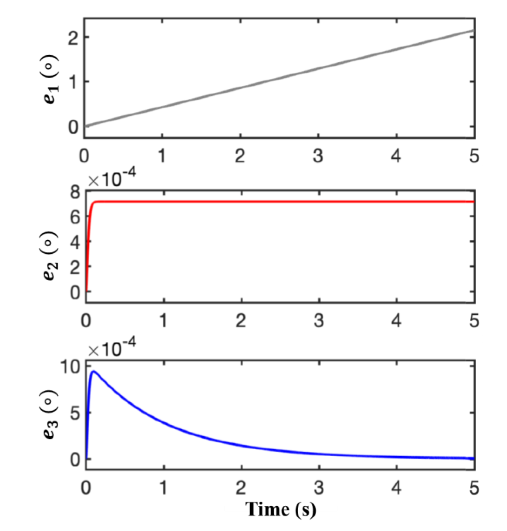
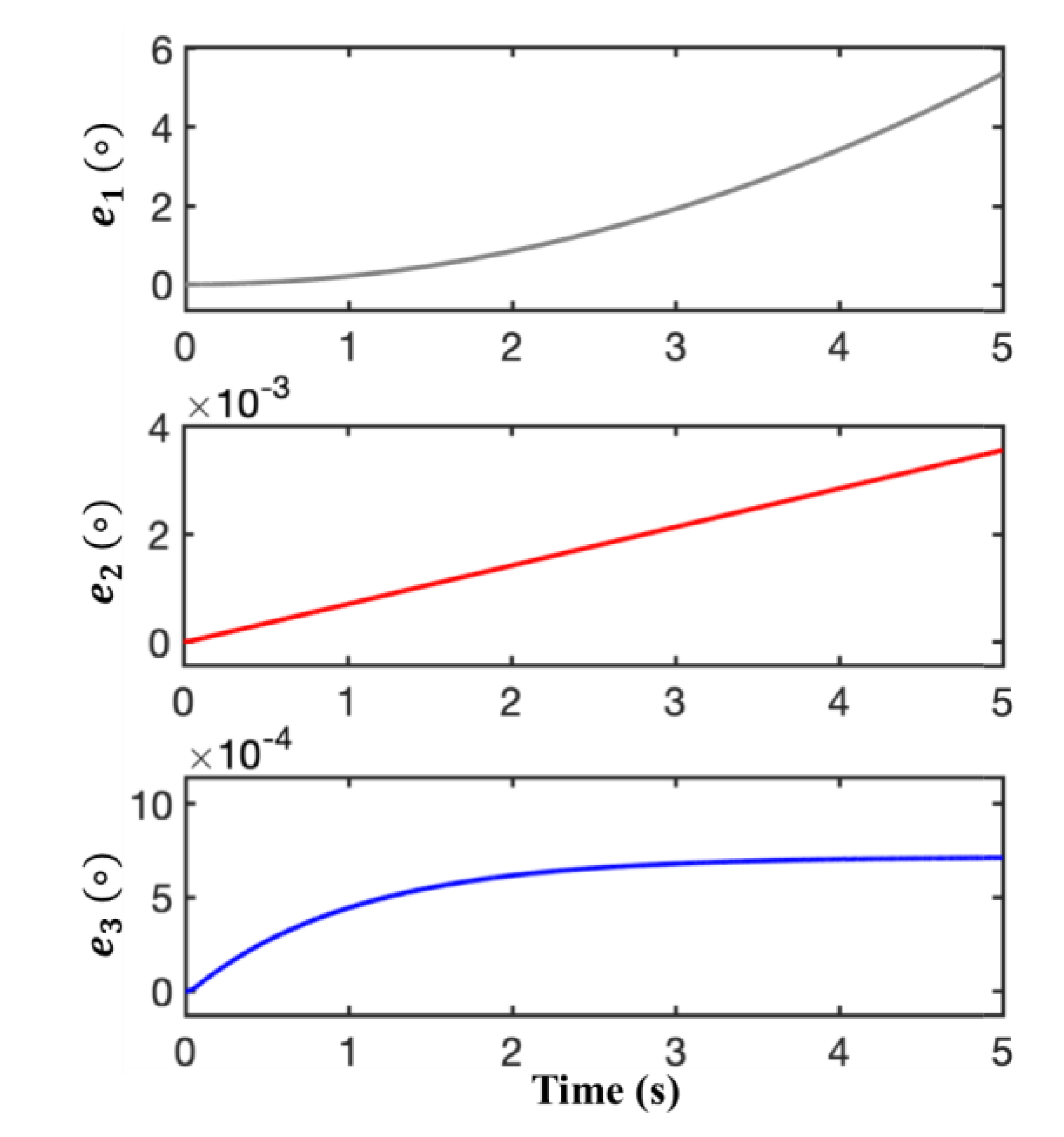
Figure 7 compares the estimation accuracy under the condition of θ = 4πt3. e1 of conventional ATO shows a large output error range, which presents a theoretically expected linearly increasing trend (at 5 s, e1 = 2.18 degrees). e2 and e3 of Figure 7 present that although there is relatively large overshoot and longer settling time, when the systems have enough time to attain steady state, the proposed ATO will present zero position estimation error and type-III ATO will keep a position estimation error of around 7 × 10⁻⁴ degree.
In order to show the improved accuracy of the ATO even under the condition of higher-order sharp change, we carried out the simulation with the input of θ = πt4. As shown in Figure 8, compared with accumulative errors of 5.3 degrees and 0.0036 degree at 5 s from the conventional and type-III ATO, the proposed one only demonstrates a steady-state error of 7.1 × 10⁻⁴ degree.
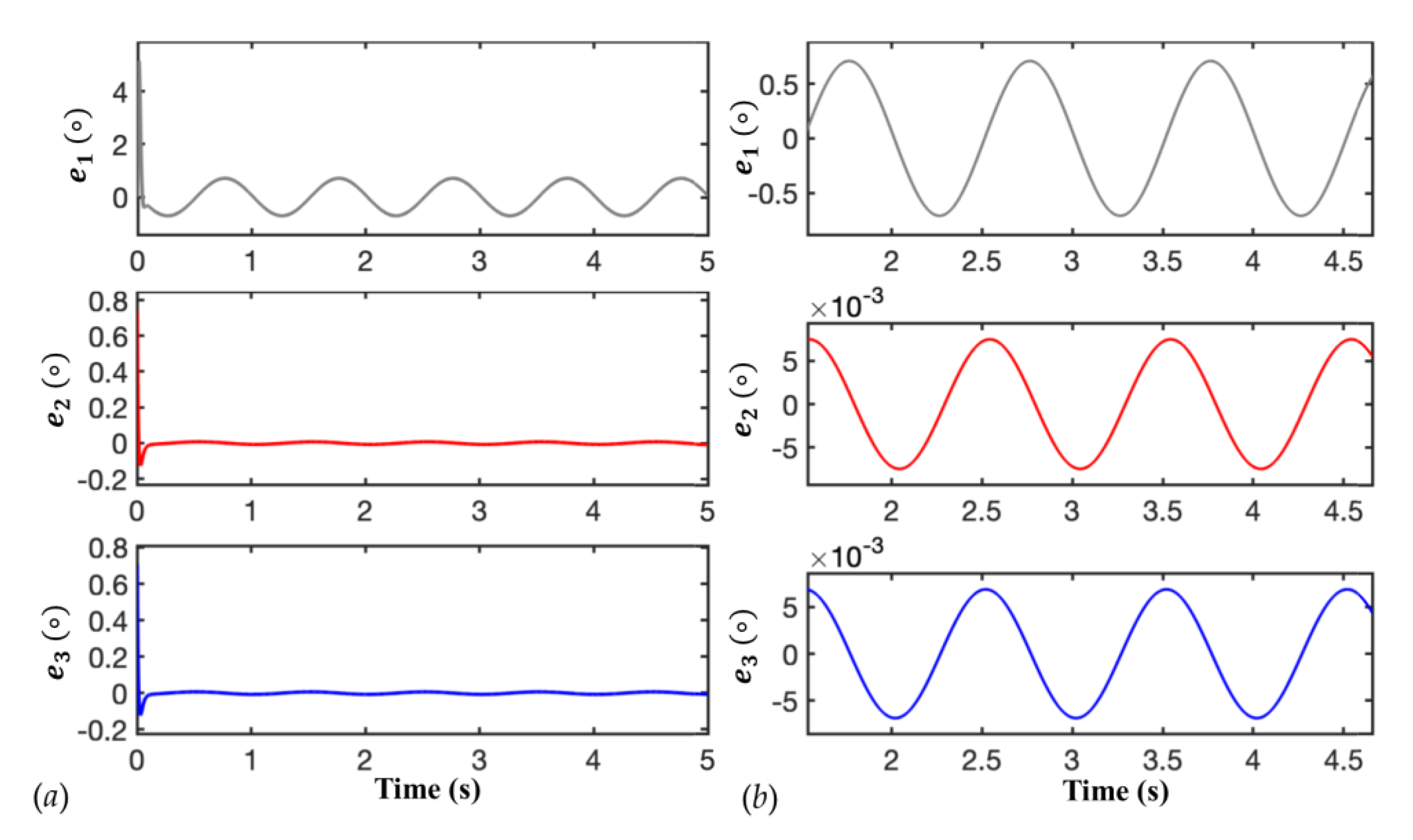
Figure 9 demonstrates the estimation errors when the input is set as θ = 2π + πsin(2πt). Figure 9a shows the evolution with a time span of 5 seconds and Figure 9b zooms in to omit the large overshoot at the beginning. In the case of sine-wave signal, the proposed ATO is also efficient in error suppression and reduces the error by two orders of magnitude compared to the conventional one.
From simulation results of different forms of input signal, we can see the proposed ATO eliminates or reduces the position errors on a large scale, which demonstrates its robustness and effectiveness in the estimation of acceleration signal. This provides the potential of the proposed ATO to be employed in high-precision position estimation for high-order signals and targeted signal with high harmonic components.
4.2. Experimental Results
In order to test the proposed ATO scheme and demonstrate its advantages in an actual situation, an experimental platform based on a hardware-in-loop (HIL) method is set up. This experimental platform mainly comprises a resolver simulator, a signal acquisition/processing board and a master computer (Figure 10).
The resolver simulator is in charge of generating two envelope signals based on the programmed rotation acceleration form. Then the envelope signals go through synchronous envelope detection and are converted into two analog output signals (usin and ucos). The signal acquisition board works as an analog-to-digital converter (ADC), which can sample the analog output signals and convert them into digital ones. The digital signals will be uploaded to the upper computer and applied with the same three ATO methods used in simulation results. It is noteworthy that, using the HIL method, the actual value of angular position can be known to evaluate error suppression performance of the RDC, whereas a practical resolver fails to provide this information [24].
In the experiments, three conditions, namely first-order acceleration, second-order acceleration and sine-wave signals, were set as inputs for three ATOs to evaluate their performance in position estimation. The sampling frequency was 1 kHz and the rest of the parameter settings were the same as in the simulation.
We first programmed the resolver simulator to make it rotate with a third-order signal regarding time, . Figure 11 shows orthogonally symmetric input of the ATO, which is the sampled sine and cosine signals after envelope detection and preprocessing methods.
Figure 12 compares the estimation position errors of the conventional ATO, type-III ATO and the proposed ATO. e1, e2 and e3 are the position errors of the conventional ATO, type-III ATO and the proposed ATO, respectively. With time increasing, the conventional ATO has a linearly growing position error and the type-III ATO has a steady state position error of 4 × 10⁻⁵ degree. And the position error of the proposed ATO is fluctuating around 0 degree, which indicates it has the ability to estimate angular position without error.
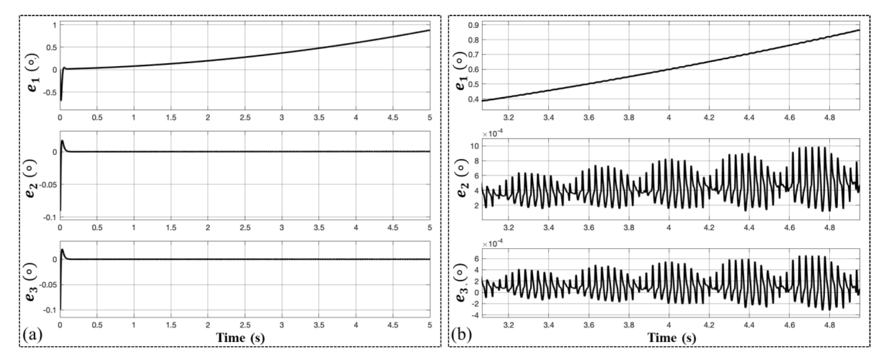
We also evaluated the performance of the three ATO schemes with a higher factor for the first-order acceleration signal. Figure 13 shows the position error with a factor of for the acceleration rotation. The results are similar to the former condition with a small acceleration factor, with conventional and type-II ATO having steady-state errors of 0.9 degree and 3 × 10⁻⁴ degree to 6 × 10⁻⁴ degree, respectively, and nearly zero error for the proposed ATO.
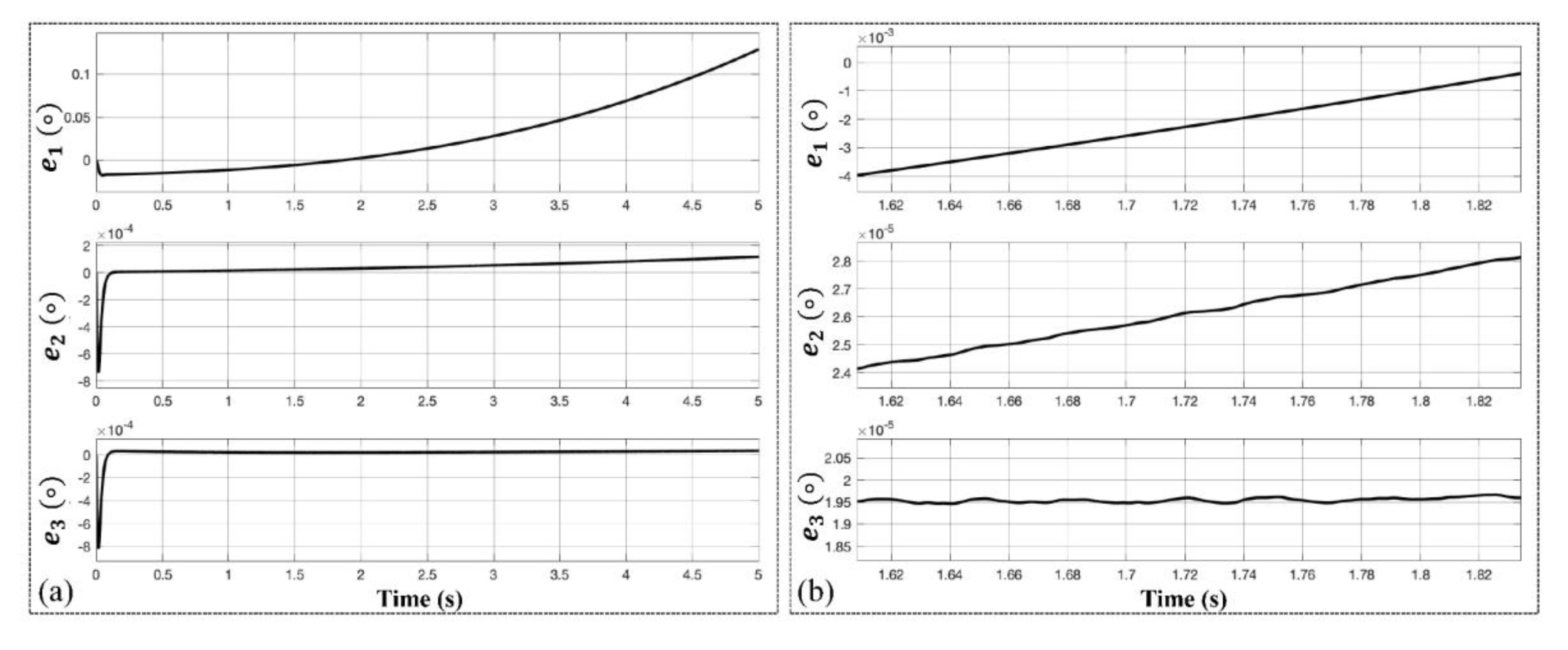
Another feature for the proposed ATO scheme (type-IV) is that it has a constant steady-state position estimation error (shown in Figure 8), compared to the former two ATOs, of which the position errors increase with time. This characteristic is easy to deduct from final-value theorem. Figure 14 verifies this by inputting an acceleration signal with fourth order regarding time. After the output of position estimation comes into steady state, errors of the former two ATO has an inclination of increasing and the proposed ATO has an error of around 1.95 × 10⁻⁵ degree. This result is better than conventional one with two orders of magnitude and the error is smaller than the type-III ATO, which ranges from 2.4 × 10⁻⁵ degree to 2.8 × 10⁻⁵ degree.
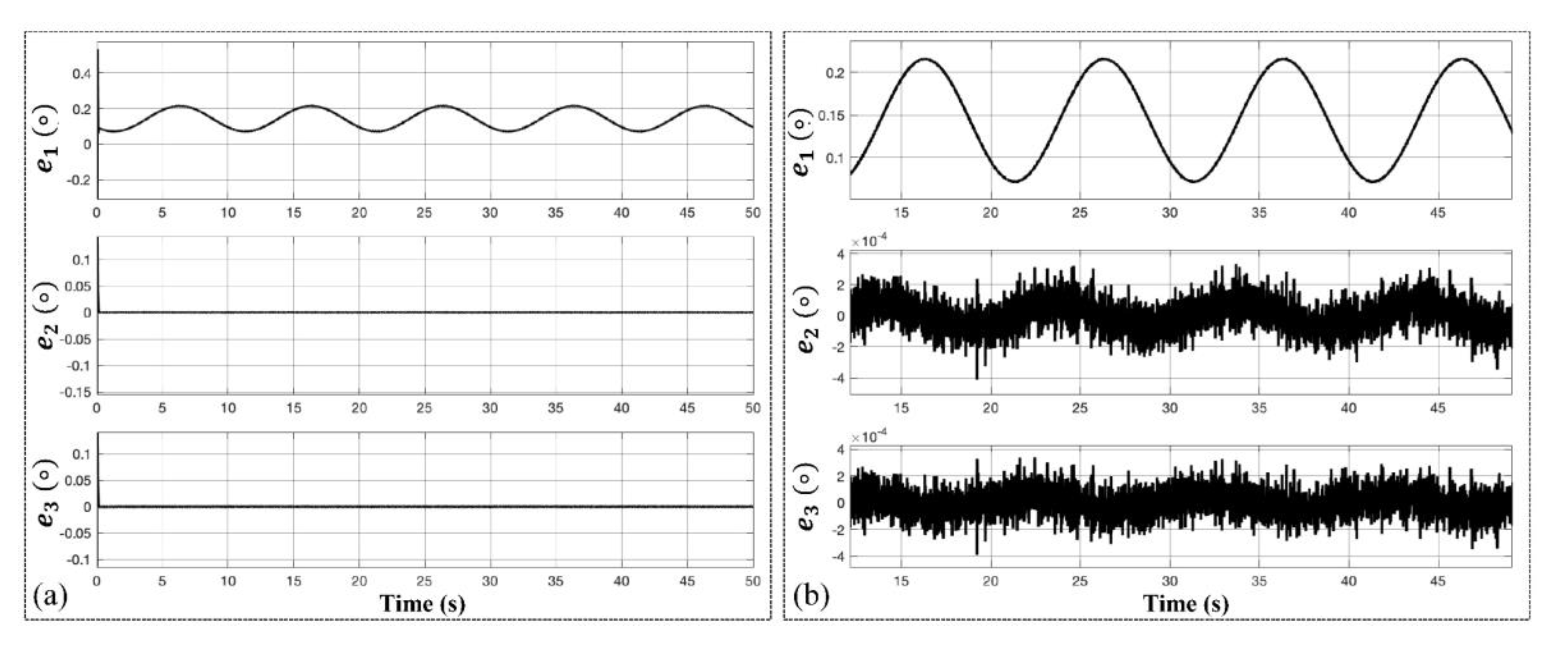
In the case of sinusoidal change, Figure 15 shows the angular position estimation error curves of the three ATO schemes when the resolver rotates at a sinusoidal form for its angular position (θ = sin t). The result demonstrates that the proposed ATO has almost the same capability of error suppression as the type-III ATO, which is an improved accuracy by three orders of magnitude in contrast to the conventional one.
4.3. Discussion
From the above-mentioned simulation and experimental results, the proposed ATO demonstrates advantages in position estimation accuracy over conventional and type-III ATO.
Hereby, in this section we discuss the novelty and application of the proposed ATO. To our best knowledge, limited research has been conducted to employ a compensation module for improved performance in ATO design, which is relatively simple, time-saving and cost-effective. Also, novelty of this ATO can be demonstrated through that without investigation of non-constant high-order acceleration signals, by simply using this feedback loop of estimated speed the accuracy of position estimation can be improved and error reduction and suppression can be achieved in a wider category of signals, the high-order acceleration signals (θ = αtn). Hence, we consider the compensation module, parameter design, accuracy improvement and time-saving implementation as points in our novelty.
As for application, this ATO holds great potential for wherever high-accuracy position estimation of a motor is needed, especially for those whose working conditions involve high speed and high acceleration rate. As formerly mentioned, the CNC machine and positioning radar are two special cases.
Since most high-speed CNC machines’ fine processing components and parts work within a travel range of only tens to hundreds of millimeters, high acceleration is required to achieve high speed and an instant stop and jerk. When dealing with irregularly shaped components, high-order acceleration signals are applied to the motor of the CNC machine.
Positioning radars need to track highly mobile artillery or other flying targets with high precision. These targets are not subject to a typical moving pattern (constant speed or constant acceleration) and high-order acceleration is usually employed to achieve posture adjustment and avoid being tracked, which places the same requirements on the motor of positioning radar.
Therefore, the proposed ATO scheme solves the urgent demands that motors performing complex accelerating patterns (high-order acceleration) call for in high-precision position estimation.
However, as is observed from the simulation results, the proposed ATO has a larger overshoot and longer settling time in transient response. Compared with two other types of ATO, the dynamic response of this ATO is not as good. Dynamic problems can be resolved by combining with other good-dynamic algorithms. When the error is large, a good-dynamic method is adopted; when the error is less than a set value, one may switch to the proposed method. This can balance both steady-state accuracy and dynamic response. Further research will investigate potential structure revision and refined design to improve its dynamic response.
5. Conclusions
In this paper, an improved compensated type-IV ATO is proposed to suppress position estimation errors with the input of high-order acceleration signal (θ = αtn). This ATO can eliminate position errors when n ≤ 3 and is effective at error reduction when n ≥ 4, which presents a solution for application in precisely estimating high-order acceleration signals. Theoretical analysis, simulation and experiments are carried out to verify and demonstrate the advantages of the proposed ATO over previous ones. We also evaluate the relationship between the parameters and bandwidth, noise level and error suppression of the ATO for succinct tuning guidance. Further research will be focused on improving the dynamic response of the proposed ATO.
Author Contributions
Conceptualization, Z.W.; methodology, H.Q.; validation, H.Q.; writing—original draft preparation, H.Q. and Z.W.
Funding
This research received no external funding.
Conflicts of Interest
The authors declare no conflict of interest.
References
- Khaburi, D.A. Software-based resolver-to-digital converter for DSP-based drives using an improved angle-tracking observer. IEEE Trans. Instrum. Meas. 2012, 61, 922–929. [Google Scholar] [CrossRef]
- Li, Y.L.; Wu, Z. High-accuracy resolver-to-digital conversion via phase locked loop based on PID controller. IOP Conf. Ser. Mater. Sci. Eng. 2018, 339, 012003. [Google Scholar] [CrossRef]
- Attaianese, C.; Tomasso, G. Position measurement in industrial drives by means of low-cost resolver-to-digital converter. Instrum. Meas. Mag. 2007, 56, 2155–2159. [Google Scholar] [CrossRef]
- Sarma, S.; Agrawal, V.K.; Udupa, S. Software-based resolver-to-digital conversion using a DSP. IEEE Trans. Ind. Electron. 2008, 55, 371–379. [Google Scholar] [CrossRef]
- Wang, F.; Shi, T.; Yan, Y.; Wang, Z.; Xia, C. Resolver-to-digital conversion based on acceleration-compensated angle tracking observer. IEEE Trans. Instrum. Meas. 2019, 68, 3494–3502. [Google Scholar] [CrossRef]
- Benammar, M.; Gonzales, A.S. A novel resolver converter based on a modified tracking method. In Proceedings of the 10th IEEE Conference on Networking, Sensing and Control, Paris, France, 10–12 April 2013; pp. 586–590. [Google Scholar] [CrossRef]
- Hoseinnezhad, R.; Harding, P. A novel hybrid angle tracking observer for resolver to digital conversion. In Proceedings of the 44th IEEE Conference on Decision and Control, Seville, Spain, 15 December 2005; pp. 7020–7025. [Google Scholar] [CrossRef]
- Sivappagari, C.M.R.; Konduru, N.R. Modified ATO algorithm based high accuracy RDC using pulse excitation. In Proceeding of the First International Conference Automation, Control, Energy and Systems, West Bengal, India, 1–2 February 2014; pp. 1–5. [Google Scholar] [CrossRef]
- Leszek, J.; Cisek, M.; Opalinski, A. Angle tracking observer for filtering rotor position estimates in sensorless electric drives. Elektronika ir Elektrotechnika 2016, 22, 38–41. [Google Scholar] [CrossRef]
- Zhao, Y.; Qiao, W.; Wu, L. Position extraction from a discrete sliding-mode observer for sensorless control of IPMSMs. In Proceedings of the IEEE International Symposium on Industrial Electronics, Hangzhou, China, 28–31 May 2012; pp. 725–730. [Google Scholar] [CrossRef]
- Hwang, S.H.; Kim, H.J.; Kim, J.M.; Liu, L.; Li, H. Compensation of amplitude imbalance and imperfect quadrature in resolver signals for PMSM drives. IEEE Trans. Ind. Appl. 2011, 47, 134–143. [Google Scholar] [CrossRef]
- Bergas, J.J.; Ferrater, S.J.; Gross, G.; Ramírez, P.R.; Galceran, A.S.; Rull, D.J. High-accuracy all-digital resolver-to-digital conversion. IEEE Trans. Ind. Electron. 2012, 59, 326–333. [Google Scholar] [CrossRef]
- Mok, H.S.; Kim, S.H.; Cho, Y.H. Reduction of PMSM torque ripple caused by resolver position error. Electron Lett. 2007, 43, 646–647. [Google Scholar] [CrossRef]
- Kwon, Y.H.; Hwang, S.H.; Kim, J.M.; Ahn, J.W. Compensation of amplitude imbalance of resolver signal for PMSM drives. In Proceedings of the IEEE 6th International Power Electronics and Motion Control Conference, Wuhan, China, 17–20 May 2009; pp. 1827–1831. [Google Scholar] [CrossRef]
- Kim, Y.H.; Kim, S. Software resolver-to-digital converter for compensation of amplitude imbalances using d-q transformation. J. Electr. Eng. Technol. 2013, 6, 1310–1319. [Google Scholar] [CrossRef]
- Yim, C.H.; Ha, I.G.; Ko, M.S. A resolver-to-digital conversion method for fast tracking. IEEE Trans. Ind. Electron. 1992, 39, 369–378. [Google Scholar] [CrossRef]
- Liu, H.; Wu, Z. Demodulation of angular position and velocity from resolver signals via chebyshev filter-based type iii phase locked loop. Electronics 2018, 7, 354. [Google Scholar] [CrossRef]
- Nguyen, H.X.; Tran, T.; Park, J.W.; Jeon, J.W. An adaptive linear-neuron-based third-order pll to improve the accuracy of absolute magnetic encoders. IEEE Trans. Ind. Electron. 2019, 66, 4639–4649. [Google Scholar] [CrossRef]
- Ellis, G.; Krah, J.O. Observer-based resolver conversion in industrial servo systems. In Proceedings of the Power Conversion Intelligent Motion Conference, Nuremberg, Germany, 19–21 June 2001; pp. 217–226. [Google Scholar]
- Hoseinnezhad, R. Position sensing in brake-by-wire callipers using resolvers. IEEE Trans. Veh. Technol. 2006, 55, 924–932. [Google Scholar] [CrossRef]
- Caruso, M.; Tommaso, A.O.D.; Genduso, F.; Miceli, R.; Galluzzo, G.R. A DSP-based resolver-to-digital converter for high-performance electrical drive applications. IEEE Trans. Ind. Electron. 2016, 63, 4042–4051. [Google Scholar] [CrossRef]
- Zhang, J.; Wu, Z. Composite state observer for resolver-to-digital conversion. Meas. Sci. Technol. 2017, 28, 065103. [Google Scholar] [CrossRef]
- Celikel, R. ANN based angle tracking technique for shaft resolver. Measurement 2019, 148, 106910. [Google Scholar] [CrossRef]
- Wu, Z.; Li, Y. High-accuracy automatic calibration of resolver signals via two-step gradient estimators. IEEE Sens. J. 2018, 18, 2883–2891. [Google Scholar] [CrossRef]
Figure 1.
Schematic block diagrams of a resolver and resolver-to-digital conversion (RDC).
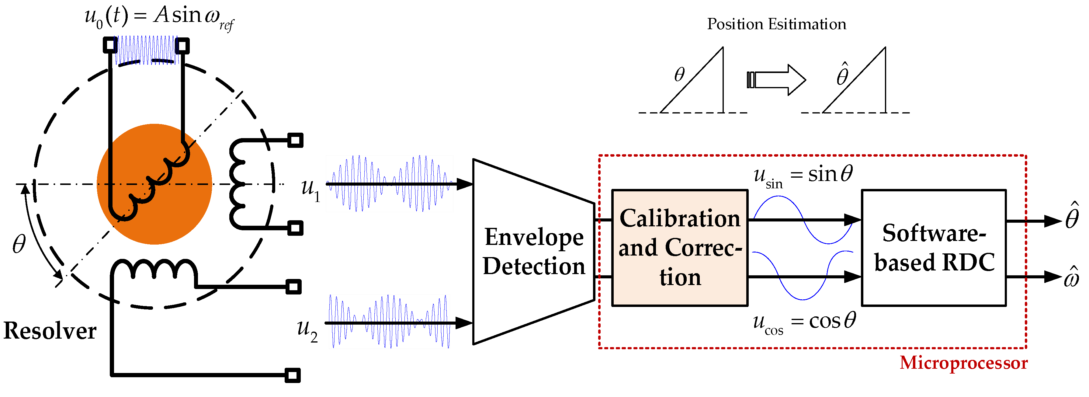
Figure 2.
Block diagram of a conventional phase-locked loop (PLL)-based angle tracking observer (ATO): (a) actual structure; (b) linearized structure.
Figure 2.
Block diagram of a conventional phase-locked loop (PLL)-based angle tracking observer (ATO): (a) actual structure; (b) linearized structure.


Figure 3.
Block diagram of a type-III ATO presented in [5].
Figure 3.
Block diagram of a type-III ATO presented in [5].

Figure 4.
Block diagram of the proposed type-IV ATO.
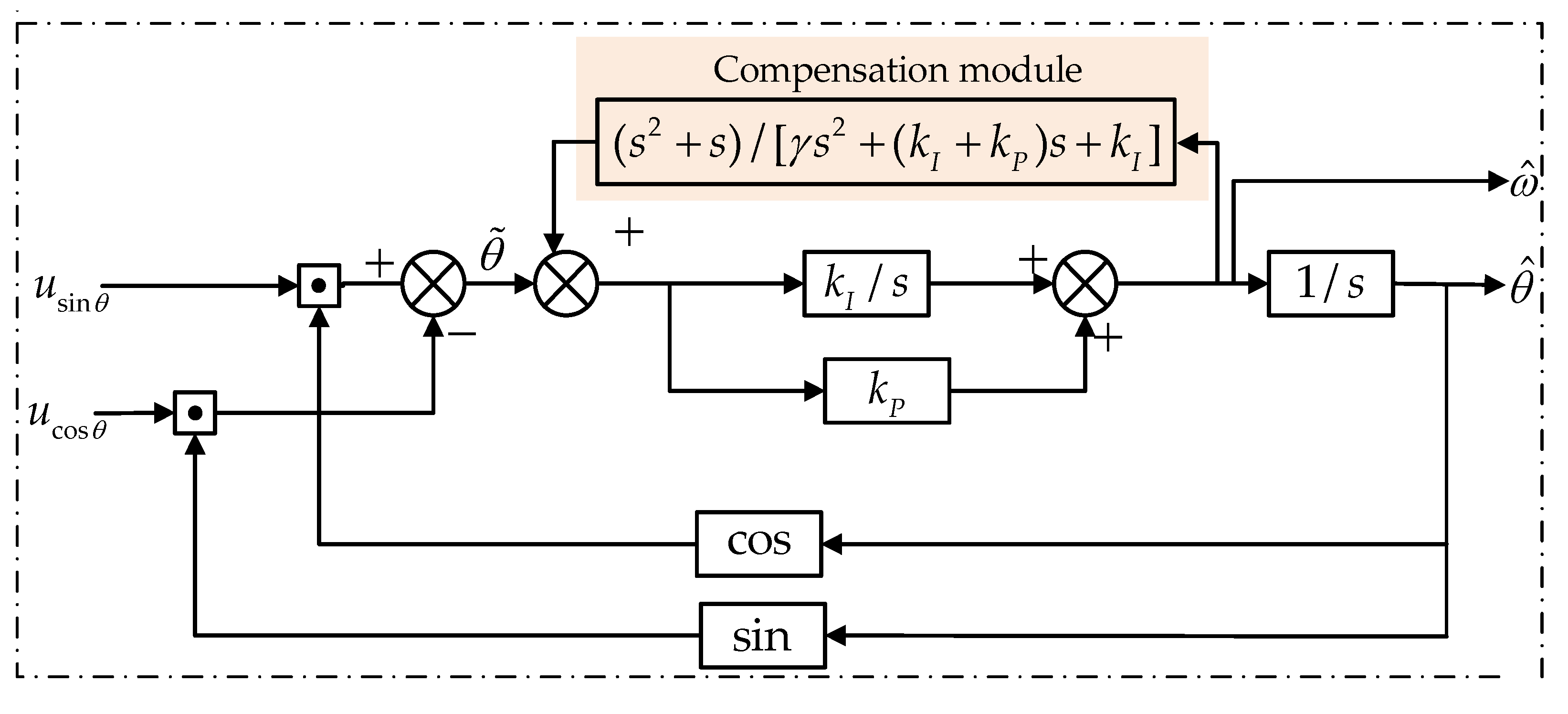
Figure 5.
(a) Demonstration of relationship between the parameters in the proposed ATO and the system’s bandwidth. γ and kP are variable from 160 to 210 and from 120 to 155, respectively, with kI determined by .
(b) Amplitude–frequency response of the proposed ATO’s error transfer function with different bandwidths (ωn = 1,300,780,520 rad/s), corresponding to γ equal to 165,185,205 and kP = 141.4, kI = 1002. (c) Relationship between the ATO’s bandwidth and parameter γ, with the other parameters determined by kP = γ − 23.6 and . The linearly fitted result corresponds well with this relationship.
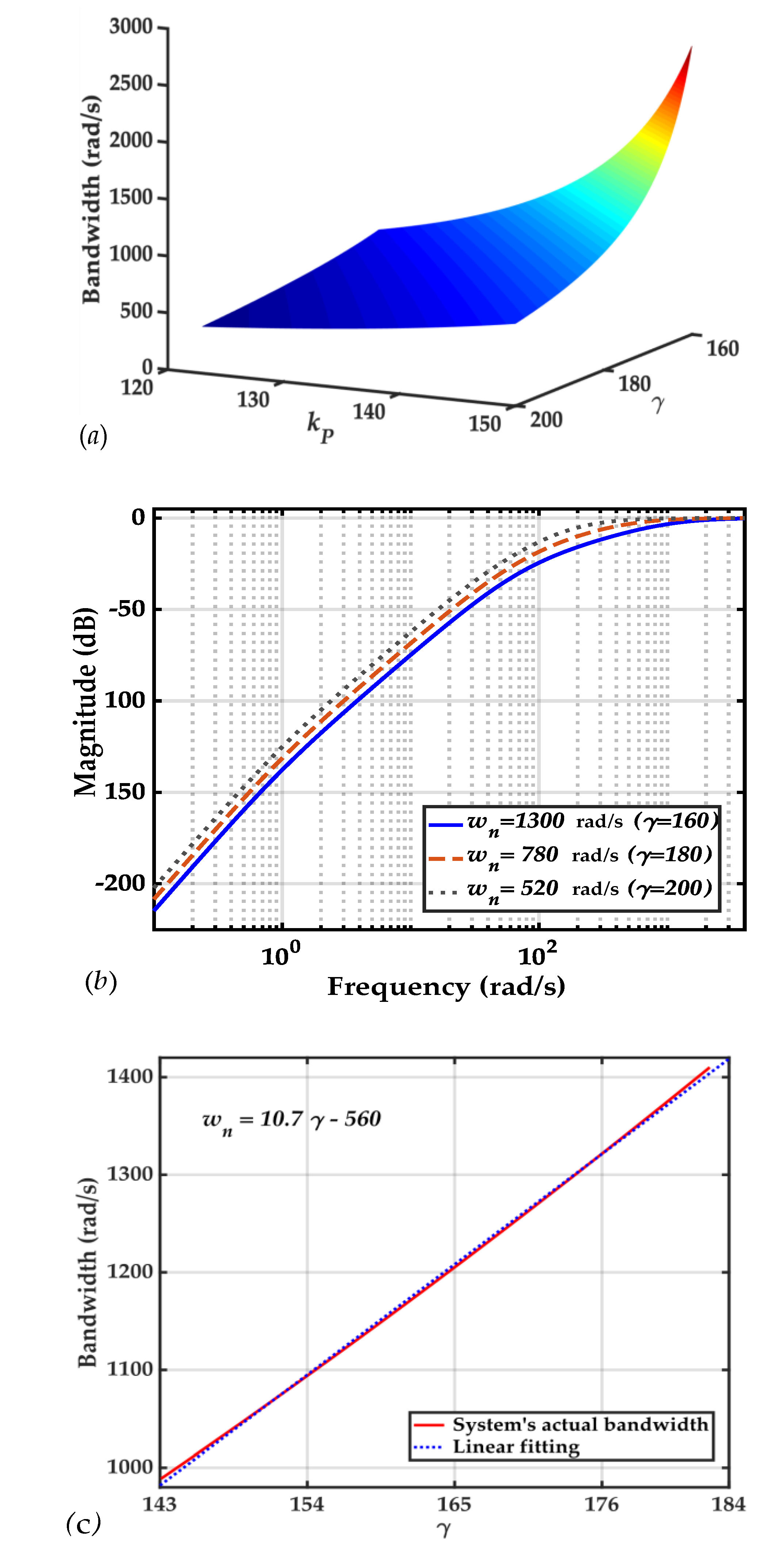
Figure 6.
Position errors of different ATOs in the simulation with a constant acceleration input (θ = 4πt2). e1, e2 and e3 are the position estimation errors of conventional ATO, type-III ATO in [5] and the proposed ATO, respectively.
Figure 6.
Position errors of different ATOs in the simulation with a constant acceleration input (θ = 4πt2). e1, e2 and e3 are the position estimation errors of conventional ATO, type-III ATO in [5] and the proposed ATO, respectively.
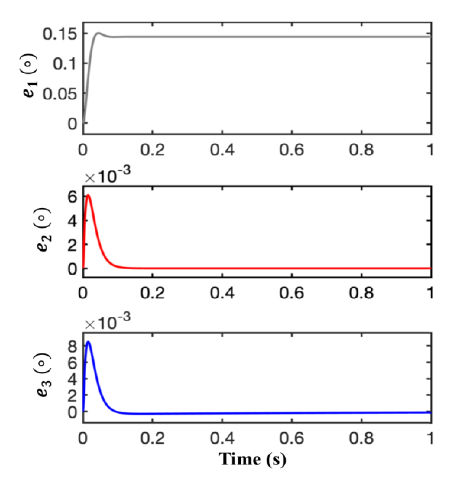
Figure 7.
Position errors of different ATOs in the simulation with a first-order acceleration input (θ = 4πt3). e1, e2 and e3 are the position estimation errors of conventional ATO, type-III ATO in [5] and the proposed ATO, respectively.
Figure 7.
Position errors of different ATOs in the simulation with a first-order acceleration input (θ = 4πt3). e1, e2 and e3 are the position estimation errors of conventional ATO, type-III ATO in [5] and the proposed ATO, respectively.

Figure 8.
Position errors of different ATOs in the simulation with a second-order acceleration input (θ = πt4). e1, e2 and e3 are the position estimation errors of conventional ATO, type-III ATO in [5] and the proposed ATO, respectively.
Figure 8.
Position errors of different ATOs in the simulation with a second-order acceleration input (θ = πt4). e1, e2 and e3 are the position estimation errors of conventional ATO, type-III ATO in [5] and the proposed ATO, respectively.

Figure 9.
Position errors of different ATOs in the simulation with a sine-wave input, θ = 2π + πsin(2πt). e1, e2 and e3 are the position estimation errors of conventional ATO, type-III ATO in [5] and the proposed ATO, respectively. (a) Evolution of e1, e2 and e3 with a time span of 5 seconds; (b) zoomed-in view of e1, e2 and e3.

Figure 10.
Structure of experimental platform for the hardware-in-loop (HIL) method.
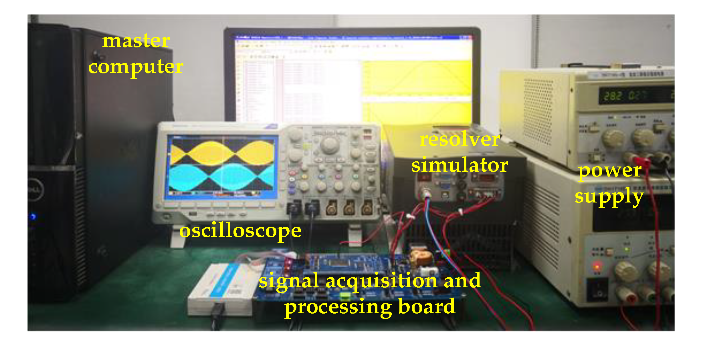
Figure 11.
Demonstration of typical sine and cosine signals after envelope detection for ,
recorded from the signal acquisition board.
Figure 11.
Demonstration of typical sine and cosine signals after envelope detection for ,
recorded from the signal acquisition board.
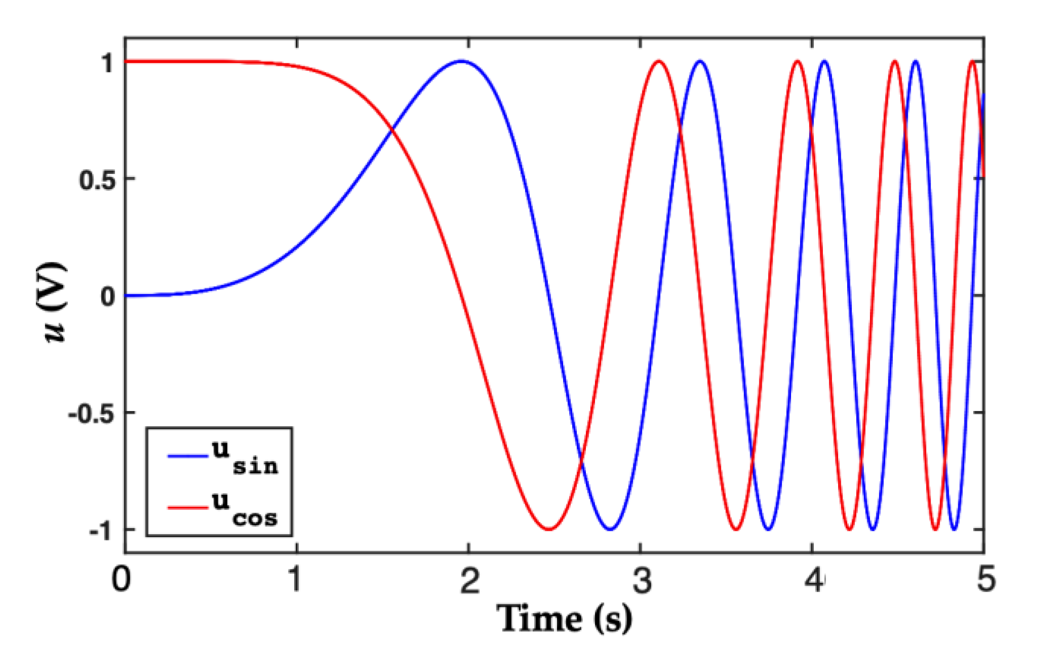
Figure 12.
Experimental results of position estimation errors for the three kinds of ATOs at an acceleration signal of .
e1, e2 and e3 are the estimation errors of the conventional ATO, type-III ATO and the proposed ATO, respectively. (a) Errors’ evolution with a time span of 5 s. (b) Zoomed-in view of e1, e2 and e3.
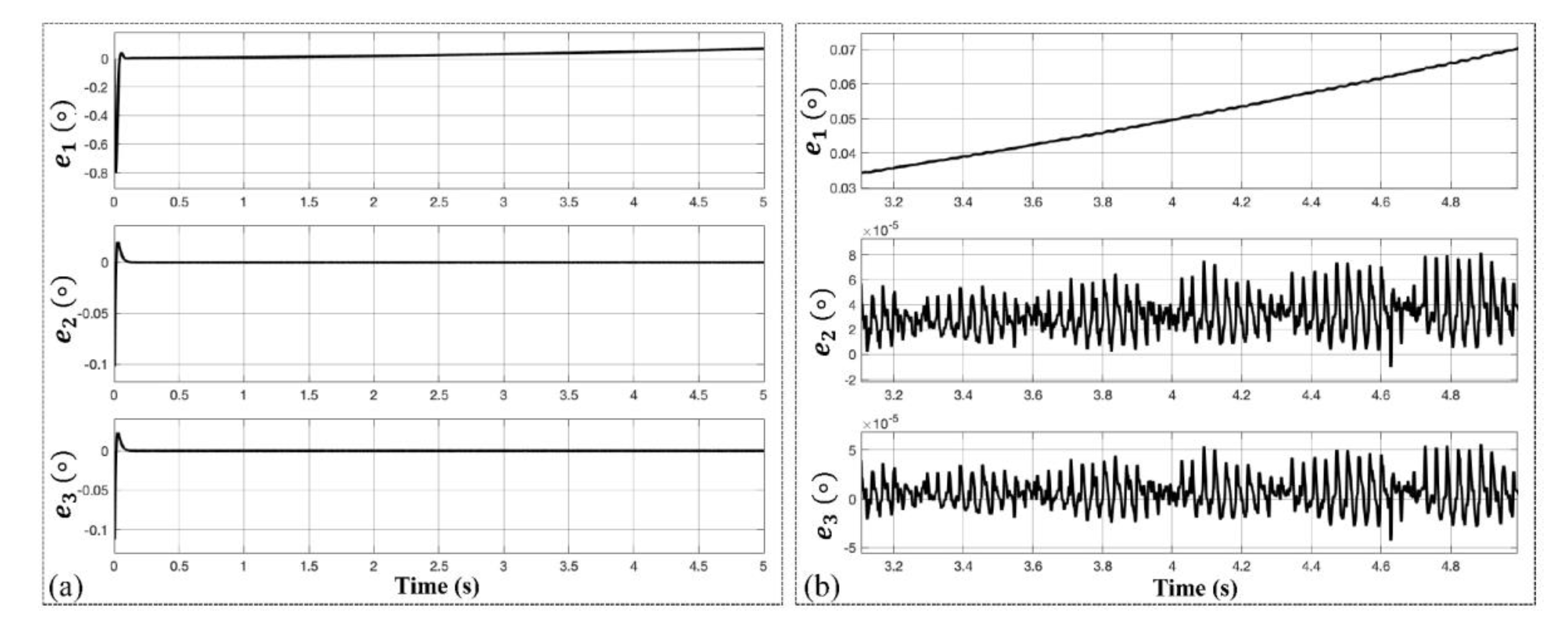
Figure 13.
Experimental results of position estimation errors for the three kinds of ATOs at an acceleration signal of θ=πt3. e1, e2 and e3 are the estimation errors of the conventional ATO, type-III ATO and the proposed ATO, respectively. (a) Errors evolution with a time span of 5s. (b) Zoomed-in view of e1, e2 and e3.

Figure 14.
Experimental results of position estimation errors for the three kinds of ATOs at an acceleration signal of .
e1, e2 and e3 are the estimation errors of the conventional ATO, type-III ATO and the proposed ATO, respectively. (a) Errors evolution with a time span of 5s. (b) Zoomed-in view of e1, e2 and e3.

Figure 15.
Experimental results of position estimation errors for the three kinds of ATOs at an acceleration signal of θ=sin t. e1, e2 and e3 are the estimation errors of the conventional ATO, type-III ATO and the proposed ATO, respectively. (a) Errors evolution with a time span of 5s. (b) Zoomed-in view of e1, e2 and e3.

Table 1.
Parameters of the three ATOs.
| Method | kI | kP | T | γ |
|---|---|---|---|---|
| Conventional ATO | 1002 | 141.4 | N/A | N/A |
| Type-III ATO in [5] | 1002 | 141.4 | 0.0158 | N/A |
| The proposed ATO | 1002 | 141.4 | N/A | 165 |
© 2019 by the authors. Licensee MDPI, Basel, Switzerland. This article is an open access article distributed under the terms and conditions of the Creative Commons Attribution (CC BY) license (http://creativecommons.org/licenses/by/4.0/).
Share and Cite
MDPI and ACS Style
Qin, H.; Wu, Z. Angle Tracking Observer with Improved Accuracy for Resolver-to-Digital Conversion. Symmetry 2019, 11, 1347. https://doi.org/10.3390/sym11111347
AMA Style
Qin H, Wu Z. Angle Tracking Observer with Improved Accuracy for Resolver-to-Digital Conversion. Symmetry. 2019; 11(11):1347. https://doi.org/10.3390/sym11111347
Chicago/Turabian StyleQin, Haoye, and Zhong Wu. 2019. "Angle Tracking Observer with Improved Accuracy for Resolver-to-Digital Conversion" Symmetry 11, no. 11: 1347. https://doi.org/10.3390/sym11111347
Note that from the first issue of 2016, this journal uses article numbers instead of page numbers. See further details here.