Hydrodynamic-Interaction Analysis of an Autonomous Underwater Hovering Vehicle and Ship with Wave Effects


Abstract
:1. Introduction
2. Mathematical Model
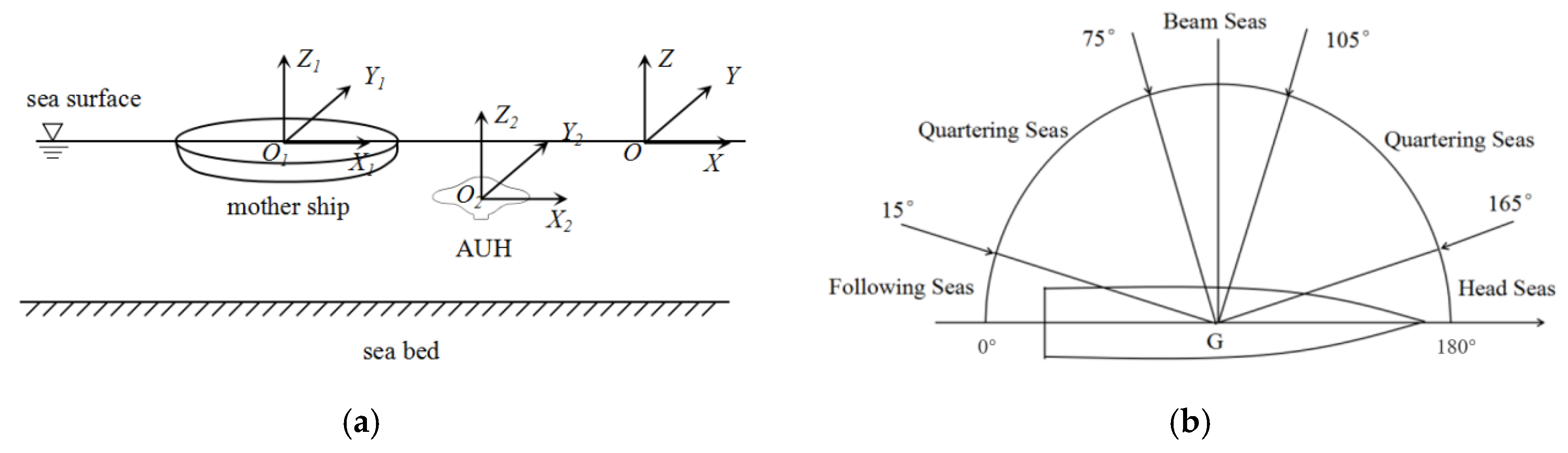
2.1. Coordinate System and Wave-Encounter Angle
2.2. Potential Surface-Panel Method
3. Simulation Results
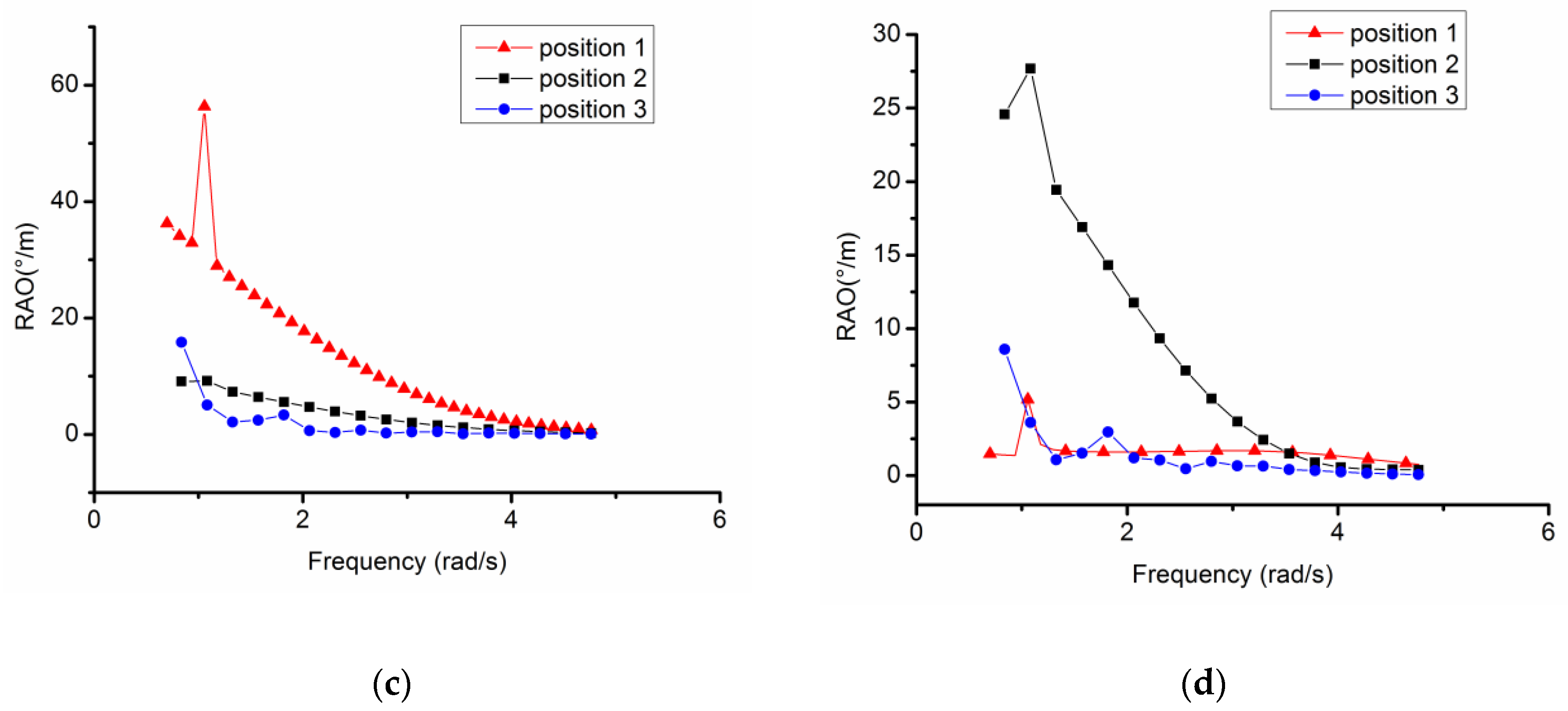
3.1. Variations of Motion RAOs in AUH–Ship Interactions
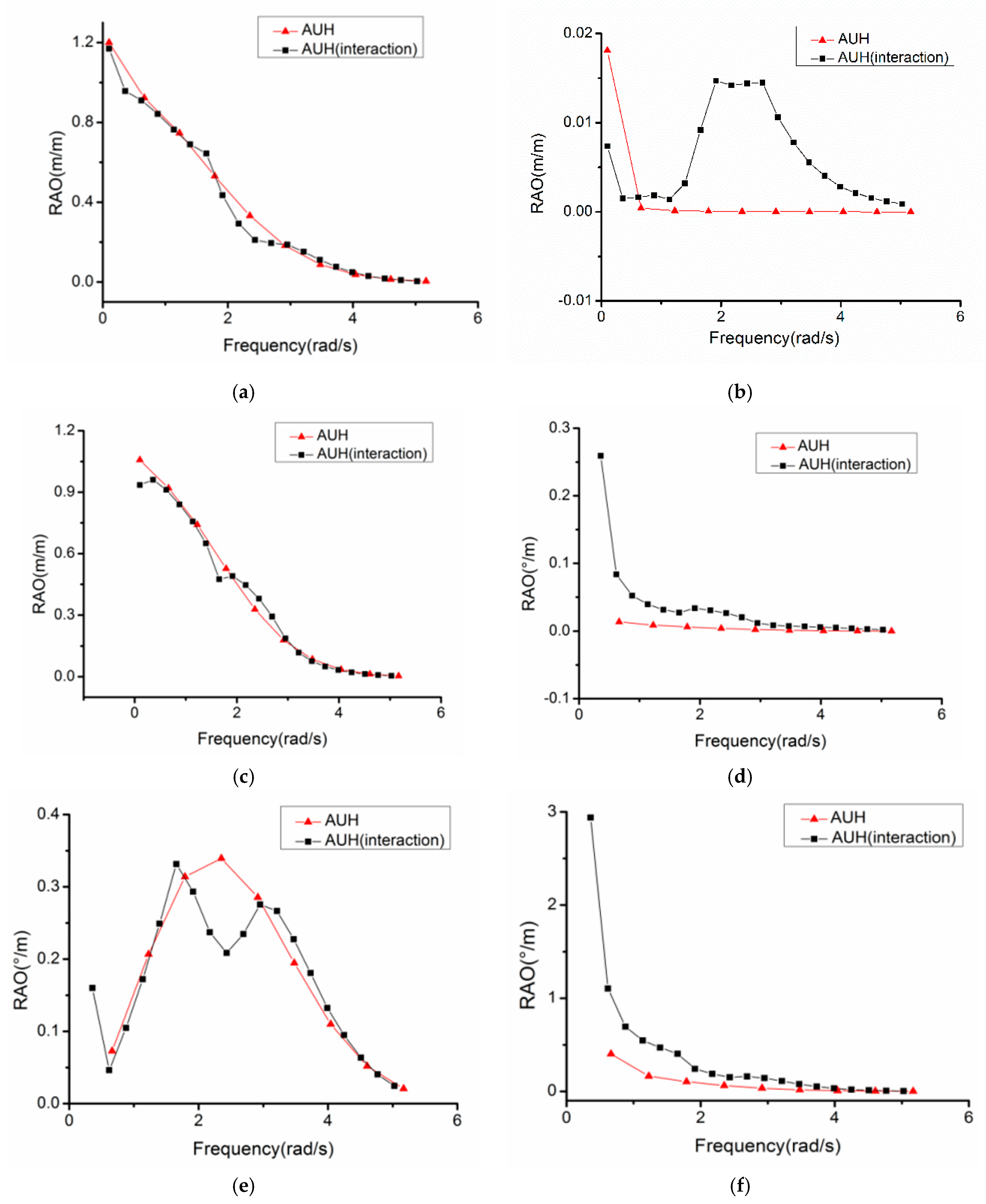
3.2. Comparing AUH and AUH–Ship RAOs in Optimal Positions
3.3. Hydrodynamic Interaction at Different Inflow Velocities
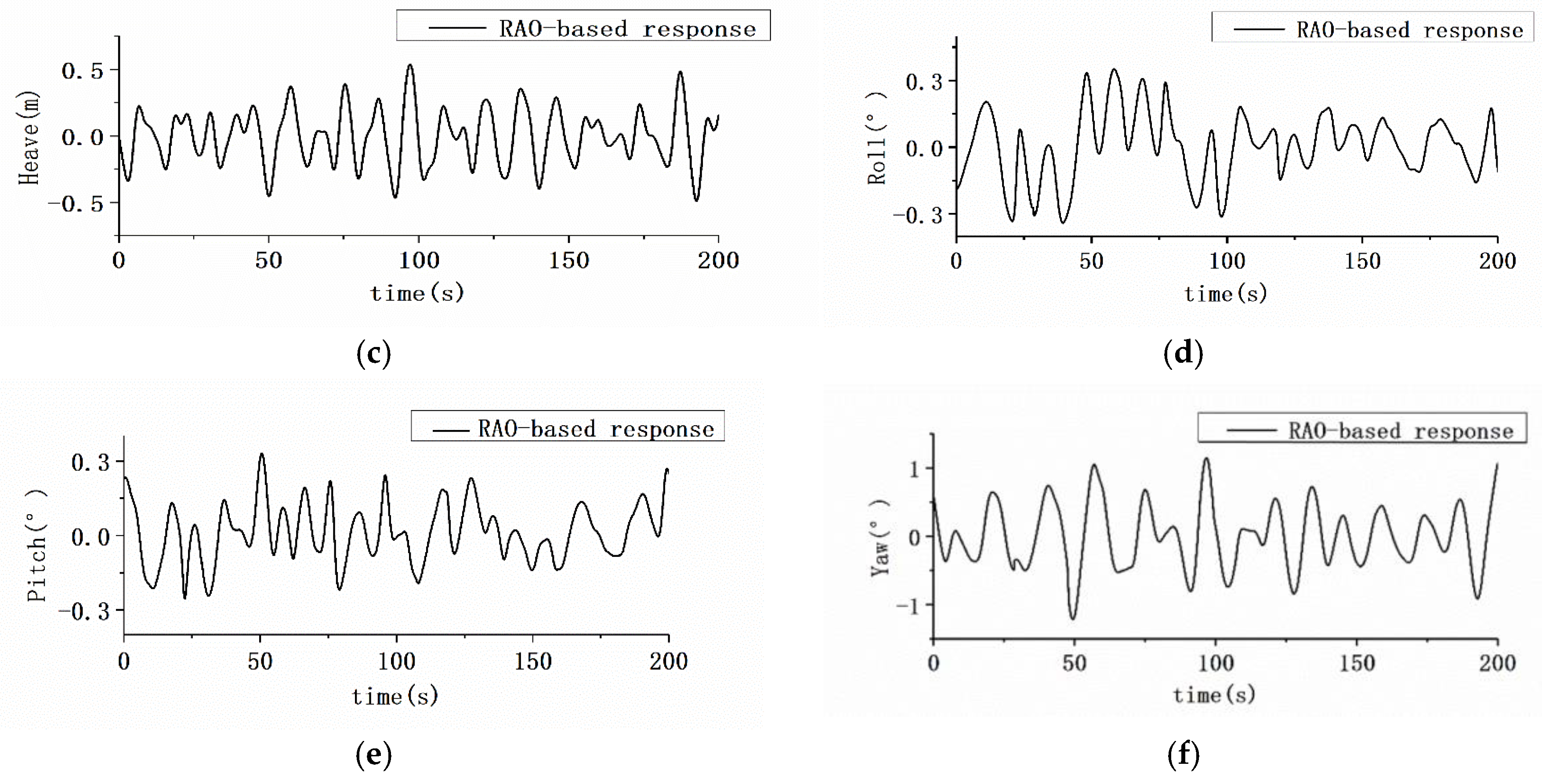
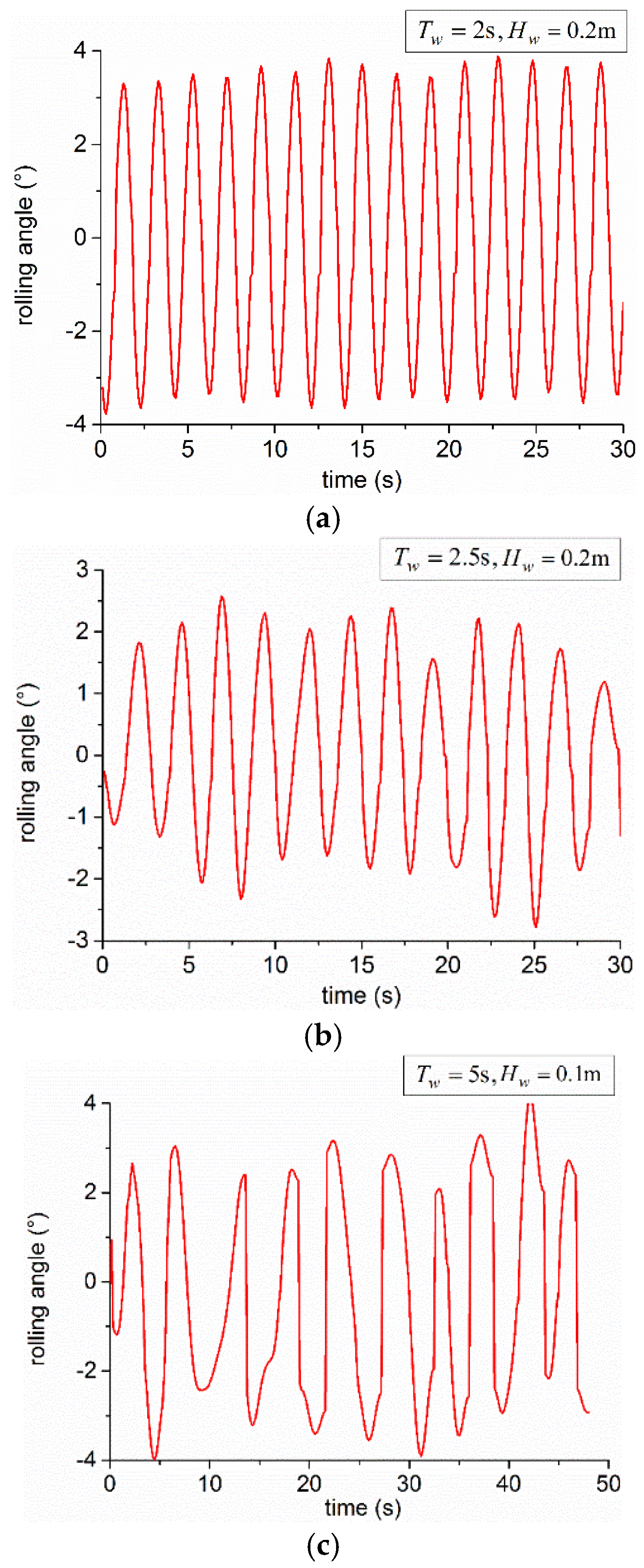
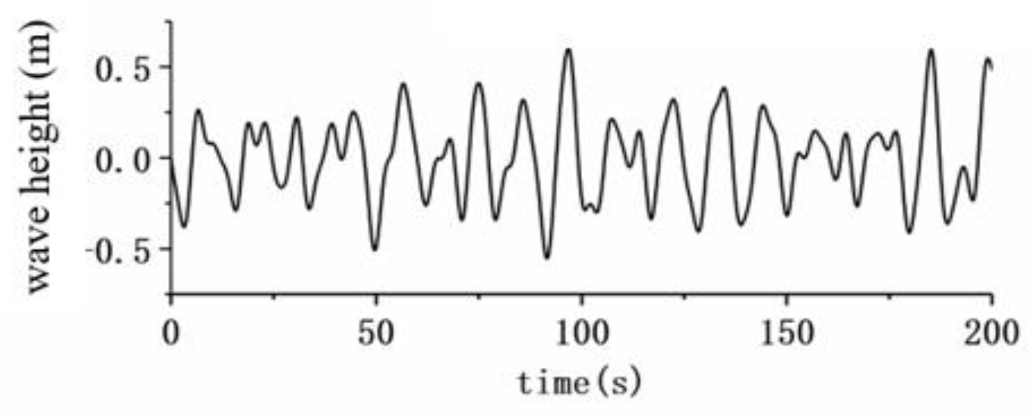
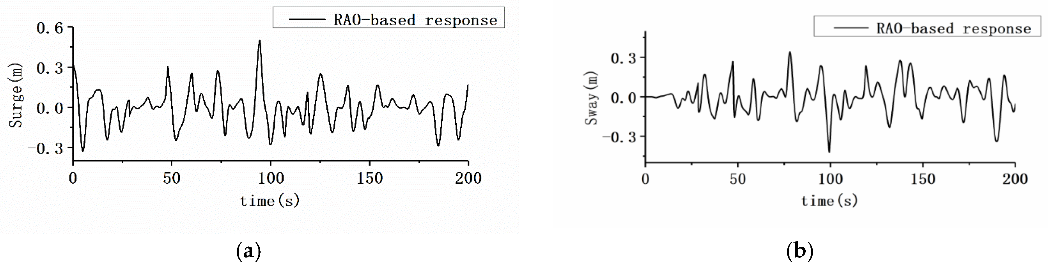
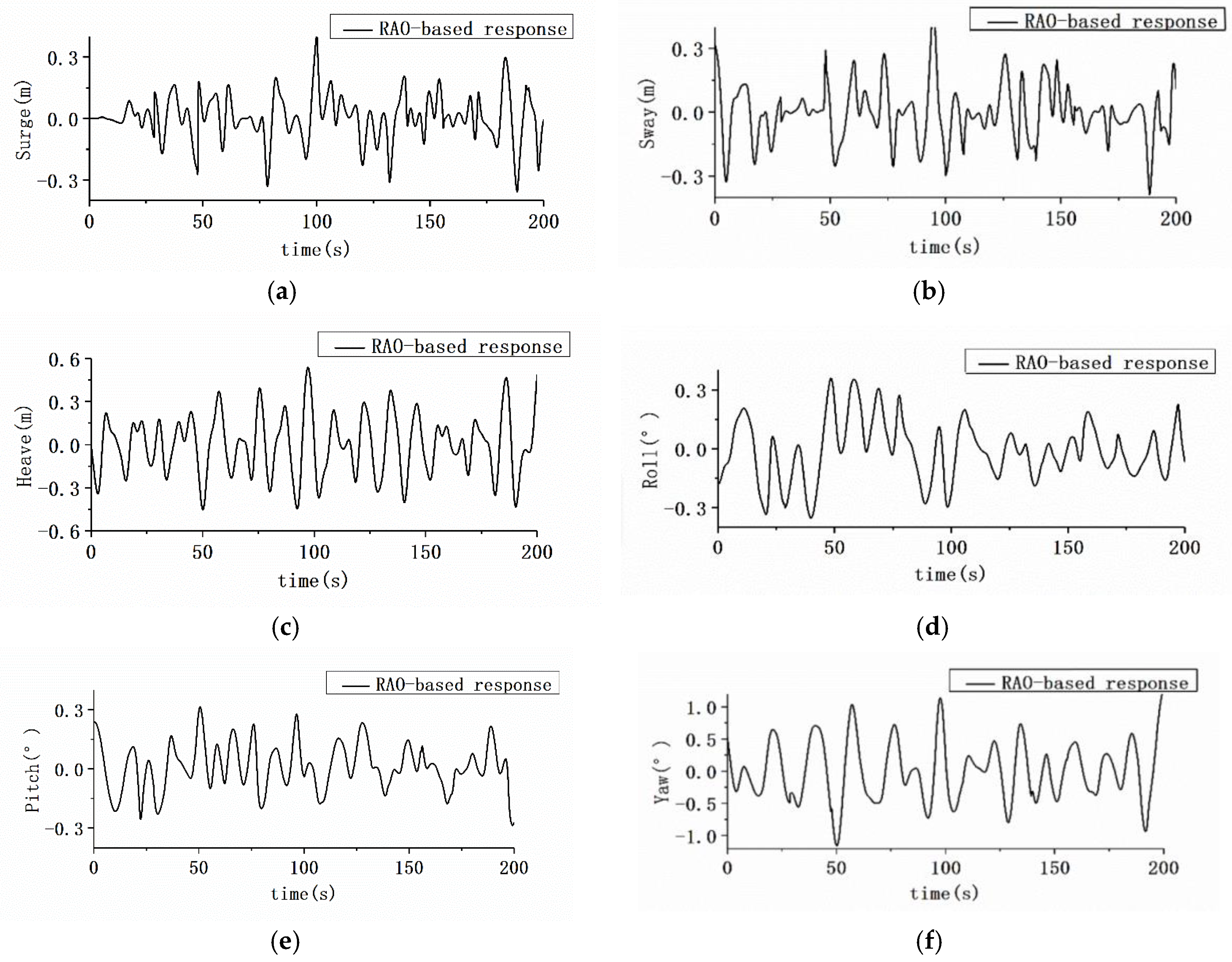
3.4. AUH–Ship Interaction Motion in Irregular Waves
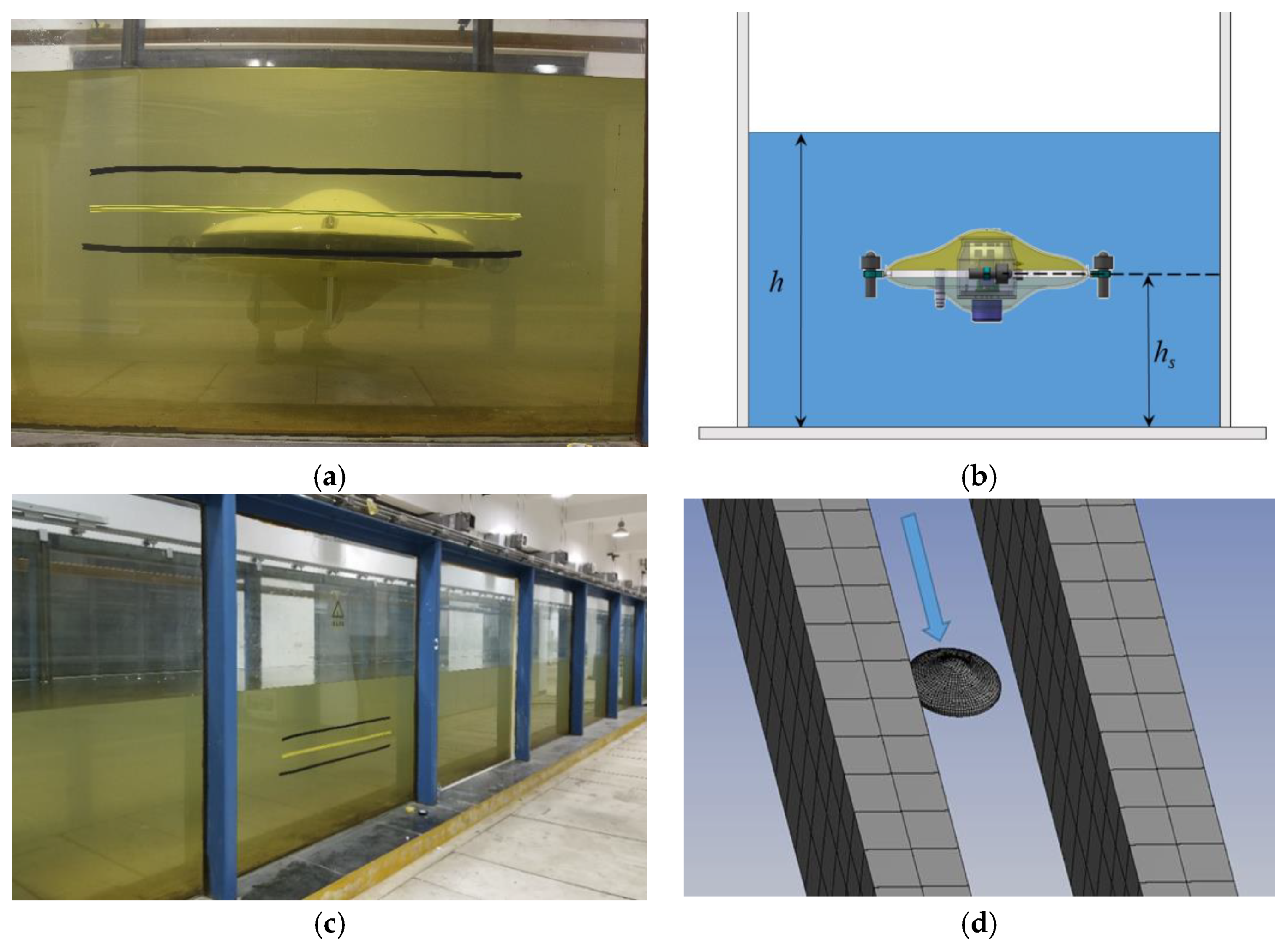
4. Experiment Validation
5. Conclusions
Author Contributions
Acknowledgments
Conflicts of Interest
Nomenclature
| \ | Velocity potential |
| U | AUH speed |
| –Ux | AUH sailing at a constant speed U |
| Perturbation potential induced byAUH presence | |
| Body boundary | |
| Normal velocity on the AUH boundary | |
| Sea-bottom boundary | |
| Wave-encounter frequency | |
| ФI | Velocity potential of incident wave |
| ФD | Diffraction power of multifloating system |
| ФR1 | Radiation potential of floating body 1 in multifloating system |
| ФR2 | Radiation potential of floating body 2 in multifloating system |
| Re{} | Real part of amount in {} |
| Wave height | |
| Position of AUH in body-fixed coordinates | |
| Distance from bottom to center of gravity | |
| CG, CB | Center of gravity, center of buoyancy |
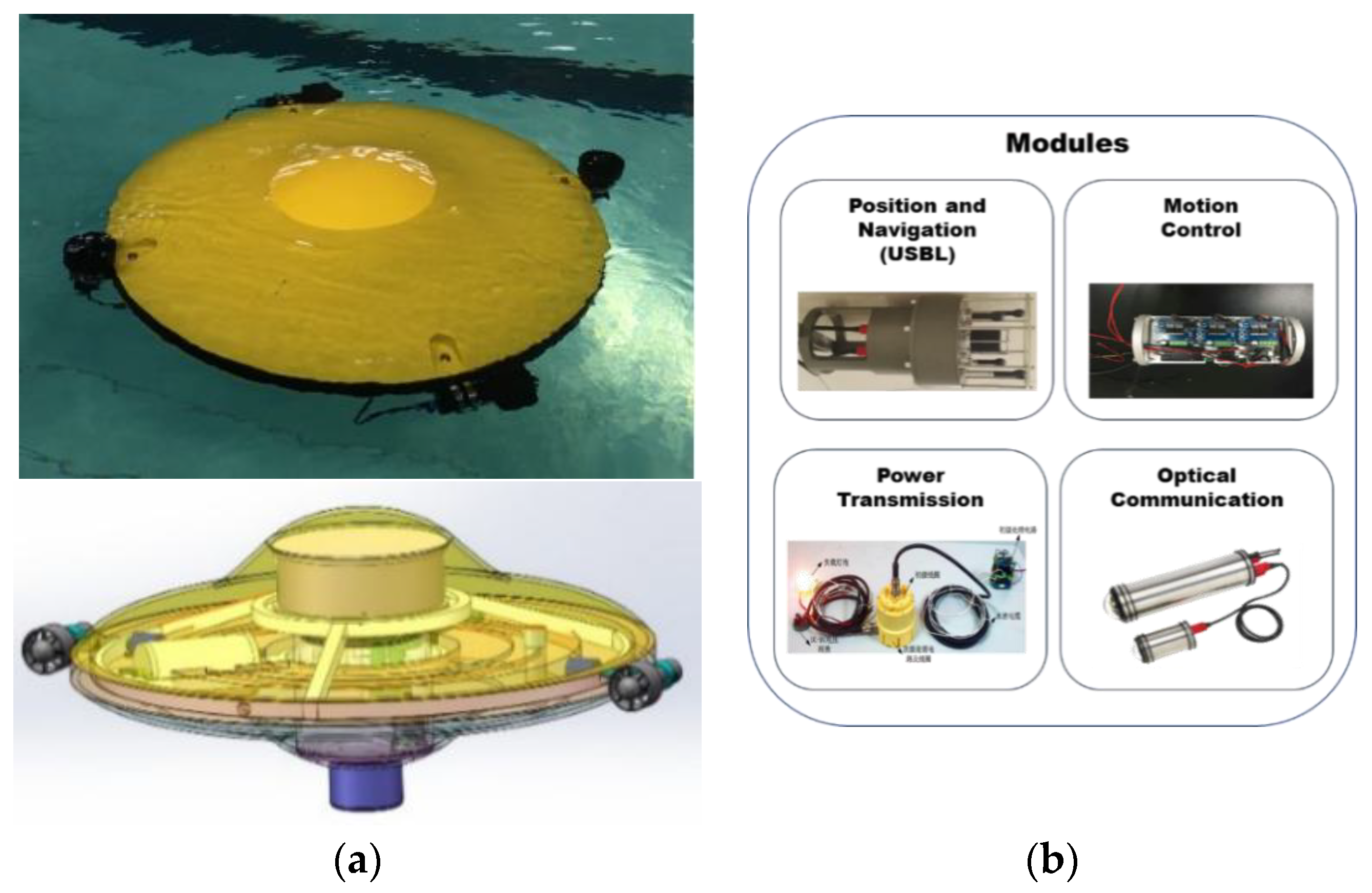
| AUH | Autonomous Underwater Helicopter |
| AUH–Ship | Study on hydrodynamic interaction between AUH and Ship |
| Wave height | |
| Bottom clearance coefficient | |
| T | AUH height |
| RAO | Response amplitude operator |
| Wave encounter angle | |
| Seaway spectrum | |
| Response spectrum of r in 6-DOF of surge, sway, heave, roll, pitch, and yaw | |
| U’ | Wind speed at height of 19.5 m |
| Magnitude of i-DOF of floating body | |
| t | Nearest vertical distance between AUH and slope |
| Wave period | |
| Critical damping | |
| Rolling inertia mass | |
| Rolling stiffness matrix | |
| Stiffness of corresponding degrees of freedom | |
| Added mass inertia mass | |
| BG | Vertical distance between the CB and CG |
| RAO | Response Amplitude Operator |
References
- Ribas, D.; Palomeras, N.; Ridao, P.; Carreras, M.; Mallios, A. Girona 500 AUV: From Survey to Intervention. IEEE/ASME Trans. Mechatron. 2012, 17, 46–53. [Google Scholar] [CrossRef]
- Yang, R.; Clement, B.; Mansour, A.; Li, M.; Wu, N. Modeling of a Complex-Shaped Underwater Vehicle for Robust Control Scheme. J. Intell. Robot. Syst. 2015, 80, 491–506. [Google Scholar] [CrossRef]
- Chen, Q.; Su, R. Analysis of launch and recovery UUV model for submarine. Ship Sci. Technol. 2011, 33, 146–149. [Google Scholar]
- Sarda, E.I.; Dhanak, M.R. A USV-Based Automated Launch and Recovery System for AUVs. IEEE J. Ocean. Eng. 2017, 42, 37–55. [Google Scholar] [CrossRef]
- Wu, L.; Li, Y.; Su, S.; Yan, P.; Qin, Y. Hydrodynamic Analysis of AUV Underwater Docking with a Cone-Shaped Dock under Ocean Currents. Ocean Eng. 2014, 85, 110–112. [Google Scholar] [CrossRef]
- Xie, N.; Iglesias, G.; Hann, M.; Pemberton, R.; Greaves, D. Experimental Study of Wave Loads on a Small Vehicle in Close Proximity to a Large Vessel. Appl. Ocean Res. 2019, 83, 77–87. [Google Scholar] [CrossRef]
- Skomal, G.B.; Hoyos-Padilla, E.M.; Kukulya, A.; Stokey, R. Subsurface Observations of White Shark Carcharodon Carcharias Predatory Behaviour using an Autonomous Underwater Vehicle. J. Fish Biol. 2015, 87, 1293–1312. [Google Scholar] [CrossRef]
- Leong, Z.Q.; Ranmuthugala, D.; Penesis, I.; Nguyen, H. Quasi-Static Analysis of the Hydrodynamic Interaction Effects on an Autonomous Underwater Vehicle Operating in Proximity to a Moving Submarine. Ocean Eng. 2015, 106, 175–188. [Google Scholar] [CrossRef]
- Tian, W.; Song, B.; Ding, H. Numerical Research on the Influence of Surface Waves on the Hydrodynamic Performance of an AUV. Ocean Eng. 2019, 183, 40–56. [Google Scholar] [CrossRef]
- Mansoorzadeh, S.; Javanmard, E. An Investigation of Free Surface Effects on Drag and Lift Coefficients of an Autonomous Underwater Vehicle (AUV) using Computational and Experimental Fluid Dynamics Methods. J. Fluids Struct. 2014, 51, 161–171. [Google Scholar] [CrossRef]
- Malik, S.A.; Pan, G.; Liu, Y. Numerical Simulations for the Prediction of Wave Forces on Underwater Vehicle using 3D Panel Method Code. Res. J. Appl. Sci. Eng. Technol. 2013, 5, 5012–5021. [Google Scholar] [CrossRef]
- Lighthill, M.J. Waves and hydrodynamic loading. In Proceedings of the Second International Conference on the Behaviour of Offshore Structures, London, UK, 7–10 July 1979. [Google Scholar]
- Chen, G.-R.; Fang, M.-C. Hydrodynamic interactions between two ships advancing in waves. Ocean Eng. 2001, 28, 1053–1078. [Google Scholar] [CrossRef]
- Choi, Y.R.; Hong, S.Y. An analysis of Hydrodynamic Interaction of Floating Multi-body Using High-Order Boundary Element Method. In Proceedings of the Twelfth International Offshore and Polar Engineering Conference, Kitakyushu, Japan, 26–31 May 2002; pp. 303–308. [Google Scholar]
- Masashi, K.; Kazuaki, E.; Hiroshi, Y. Wave Drift Force and Moments on Two Ships Arranged side by side in Waves. Ocean Eng. 2005, 32, 529–555. [Google Scholar]
- Hong, S.Y.; Kim, J.H.; Cho, S.K.; Choi, Y.R.; Kim, Y.S. Numerical and Experimental study on Hydrodynamic Interaction of side-by-side moored Multiple Vessels. Ocean Eng. 2005, 32, 783–801. [Google Scholar] [CrossRef]
- Chen, C.W.; Jiang, Y.; Huang, C.H.; Ji, D.X.; Sun, G.Q.; Yu, Z.; Chen, Y. Computational fluid dynamics study of the motion stability of an autonomous underwater helicopter. Ocean Eng. 2017, 143, 227–239. [Google Scholar] [CrossRef]
- Chen, C.W.; Huang, C.H.; Dai, X.K.; Huang, H.C.; Chen, Y. Motion and Control Simulation of a Dished Autonomous Underwater Helicopter. In Proceedings of the OCEANS 2017, Anchorage, AK, USA, 18–21 September 2017; pp. 1–6. [Google Scholar]
- Chen, C.W.; Yan, N.M.; Leng, J.X.; Chen, Y. Numerical Analysis of Second-Order Wave Forces Acting on an Autonomous Underwater Helicopter using Panel Method. In Proceedings of the OCEANS 2017, Anchorage, AK, USA, 18–21 September 2017. [Google Scholar]
- Chen, C.-W.; Jiang, Y. Computational Fluid Dynamics Study of Magnus Force on an Axis-Symmetric, Disk-Type AUV with Symmetric Propulsion. Symmetry 2019, 11, 397. [Google Scholar] [CrossRef]
- Chen, C.W.; Yan, N.M. Prediction of Added Mass for an Autonomous Underwater Vehicle Moving Near Sea Bottom Using Panel Method. In Proceedings of the 2017 4th International Conference on Information Science and Control Engineering (ICISCE), Changsha, China, 21–23 July 2017; pp. 1094–1098. [Google Scholar]
- Miller, P.A.; Farrell, J.A.; Zhao, Y.; Djapic, V. Autonomous Underwater Vehicle Navigation. IEEE J. Ocean. Eng. 2010, 35, 663–678. [Google Scholar] [CrossRef]
- He, B.; Zhang, H.; Li, C.; Zhang, S.; Liang, Y.; Yan, T. Autonomous Navigation for Autonomous Underwater Vehicles Based on Information Filters and Active Sensing. Sensors 2011, 11, 10958–10980. [Google Scholar] [CrossRef]
- Pérez-Alcocer, R.; Torres-Méndez, L.A.; Olguín-Díaz, E.; Maldonado-Ramírez, A.A. Vision-Based Autonomous Underwater Vehicle Navigation in Poor Visibility Conditions using a Model-Free Robust Control. J. Sens. 2016, 2016, 1–16. [Google Scholar] [CrossRef]
- Ji, D.; Li, H.; Chen, C.W.; Song, W.; Zhu, S. Visual Detection and Feature Recognition of Underwater Target using a Novel Model-Based Method. Int. J. Adv. Robot. Syst. 2018, 15. [Google Scholar] [CrossRef]
- Rauch, C.G.; Purcell, M.J.; Austin, T.; Packard, G.J. Ship of opportunity launch and recovery system for REMUS 600 AUV’s. In Proceedings of the OCEANS 2008, Quebec City, QC, Canada, 15–18 September 2008. [Google Scholar]
- Sharp, K.; Cronin, D.; Small, D.; Swanson, R.; Augustus, T. A cocoon-based shipboard launch and recovery system for large autonomous underwater vehicles. In Proceedings of the MTS/IEEE Oceans 2001, Honolulu, HI, USA, 5–8 November 2001. [Google Scholar]
- Newman, J.N.; Landweber, L. Marine Hydrodynamics. J. Appl. Mech. 1977, 45, 457. [Google Scholar] [CrossRef]
- Joseph, D.D. Potential flow of viscous fluids: Historical notes. Int. J. Multiph. Flow 2005, 32, 285–310. [Google Scholar] [CrossRef]
- Seif, M.S.; Inoue, Y. Dynamic analysis of floating bridges. Mar. Struct. 1998, 11, 29–46. [Google Scholar] [CrossRef]
- Sun, B.; Miao, Q.; Feng, X.; Jiang, H. A Numerical Method for the Calculation of the Wave Forces Acting on a Submarine Travelling near the Free Surface. J. Ship Mech. 1997, 1, 21–26. [Google Scholar]
- Soares, C.G. Effect of spectral shape uncertainty in the short term wave-induced ship response. Appl. Ocean Res. 1990, 12, 54–69. [Google Scholar] [CrossRef]
- Perez, T. Ship Motion Control: Course Keeping and Roll Stabilisation Using Rudder and Fins; Springer: London, UK, 2005. [Google Scholar]
- Moreira, L.; Soares, C.G. H2 and H∞ Designs for Diving and Course Control of an Autonomous Underwater Vehicle in Presence of Waves. IEEE J. Ocean. Eng. 2008, 33, 69–88. [Google Scholar] [CrossRef]
- Refsnes, J.E.; Sorensen, A.J.; Pettersen, K.Y. Model-Based Output Feedback Control of Slender-Body Underactuated AUVs: Theory and Experiments. IEEE Trans. Control Syst. Technol. 2008, 16, 930–946. [Google Scholar] [CrossRef]


| Parameter | Symbol | Unit | Value |
|---|---|---|---|
| Diameter | L | m | 1.0 |
| Height | T | m | 0.44 |
| Design depth | H | m | 1000 |
| Seawater density | ρ | 1020–1030 | |
| Design speed | U | 0.5144–1.5432 | |
| Mass/payload | m | kg | 122.6/15 |
| Vertical distance between CG and CB | BG | mm | 37 |
| Battery | null | kwh/kg | 2 * 12 V–30 Ah |
| Number of thrusters/thrust | null | kg | 2/50 kgf |
| Buoyancy engines/volume | null | ml | 2/500 |
| USBL/DVL | null | null | AT: 50, 150 mm/20 kHz |
| Pressure hull | null | null | 1 |
| Position | (m) | (m) | (m) |
|---|---|---|---|
| 1 | 10 | −2.4 | −2 |
| 2 | 7 | −2.4 | −2 |
| 3 | 3 | −2.4 | −2 |
| Position | (m) | (m) | (m) |
|---|---|---|---|
| 1 | 10 | −2.4 | −2 |
| 2 | 10 | −5 | −2 |
| 3 | 10 | −10 | −2 |
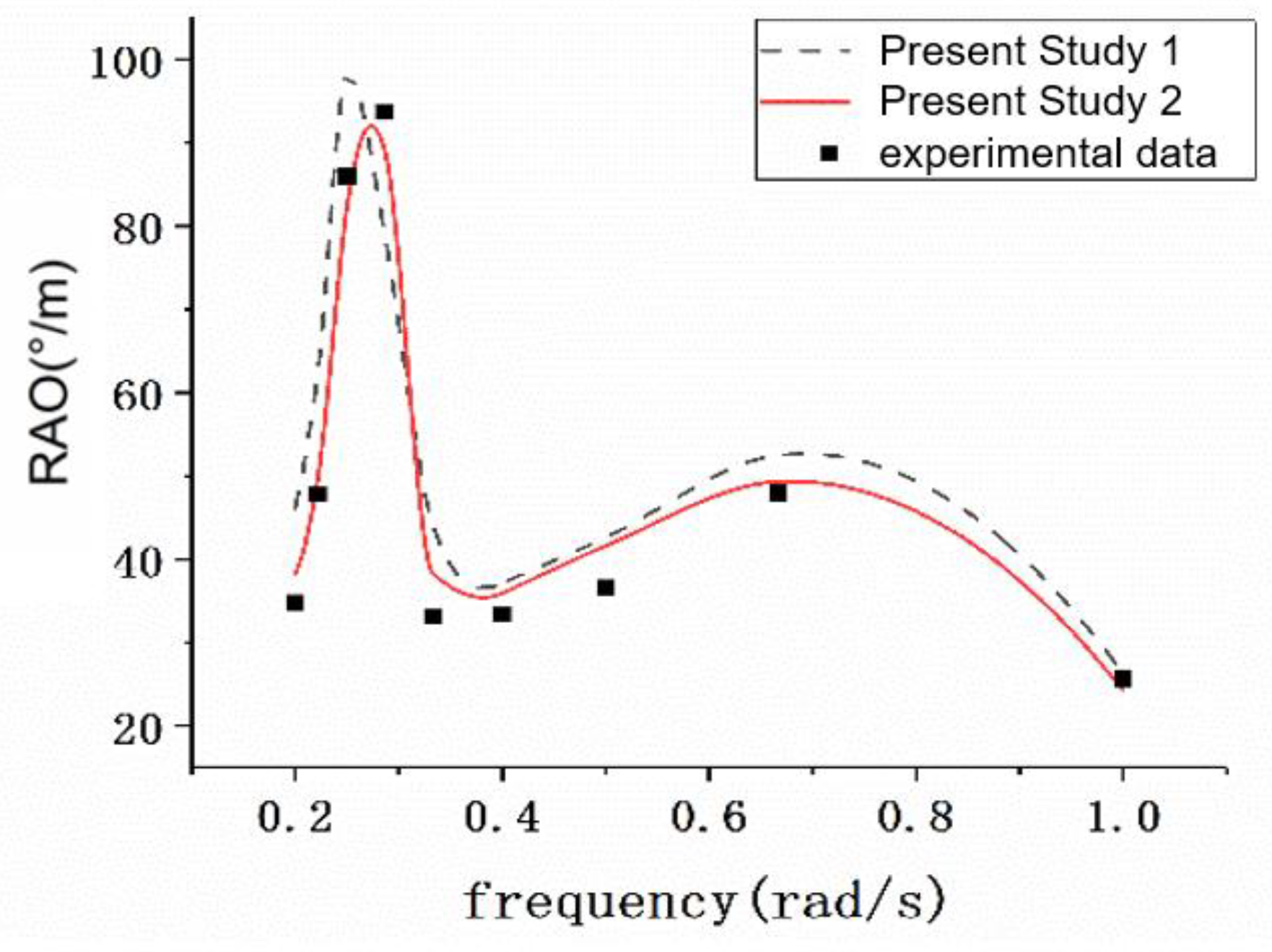
| Frequency (Hz) | Experiment Data (°/m) | Study 1 (°/m) | Error 1 | Study 2 (°/m) | Error 2 |
|---|---|---|---|---|---|
| 1 | 32.3 | 26.3 | 18.6% | 24.3 | 14.13% |
| 0.67 | 45.6 | 52.5 | 15.1% | 49.3 | 8.11% |
| 0.5 | 36.8 | 42.6 | 15.8% | 41.6 | 13.04% |
| 0.4 | 34.3 | 37.1 | 8.2% | 35.9 | 4.67% |
| 0.33 | 34.1 | 44.1 | 29.3% | 38.3 | 12.32% |
| 0.29 | 82.2 | 79.4 | 3.4% | 89.3 | 9.97% |
| 0.25 | 75.2 | 98.2 | 30.6% | 82.3 | 9.44% |
| 0.22 | 45.5 | 62.7 | 37.8% | 49.9 | 9.67% |
| 0.2 | 35.4 | 46.2 | 30.5% | 38.3 | 8.19% |
| Average error | 21.03% | 9.95% | |||
© 2019 by the authors. Licensee MDPI, Basel, Switzerland. This article is an open access article distributed under the terms and conditions of the Creative Commons Attribution (CC BY) license (http://creativecommons.org/licenses/by/4.0/).
Share and Cite
Chen, C.-W.; Chen, Y.; Cai, Q.-W. Hydrodynamic-Interaction Analysis of an Autonomous Underwater Hovering Vehicle and Ship with Wave Effects. Symmetry 2019, 11, 1213. https://doi.org/10.3390/sym11101213
Chen C-W, Chen Y, Cai Q-W. Hydrodynamic-Interaction Analysis of an Autonomous Underwater Hovering Vehicle and Ship with Wave Effects. Symmetry. 2019; 11(10):1213. https://doi.org/10.3390/sym11101213
Chicago/Turabian StyleChen, Chen-Wei, Ying Chen, and Qian-Wen Cai. 2019. "Hydrodynamic-Interaction Analysis of an Autonomous Underwater Hovering Vehicle and Ship with Wave Effects" Symmetry 11, no. 10: 1213. https://doi.org/10.3390/sym11101213
APA StyleChen, C.-W., Chen, Y., & Cai, Q.-W. (2019). Hydrodynamic-Interaction Analysis of an Autonomous Underwater Hovering Vehicle and Ship with Wave Effects. Symmetry, 11(10), 1213. https://doi.org/10.3390/sym11101213